JP2010019254A - Sealing mechanism equipped with pivot plate and rope seal - Google Patents
Sealing mechanism equipped with pivot plate and rope seal Download PDFInfo
- Publication number
- JP2010019254A JP2010019254A JP2009154500A JP2009154500A JP2010019254A JP 2010019254 A JP2010019254 A JP 2010019254A JP 2009154500 A JP2009154500 A JP 2009154500A JP 2009154500 A JP2009154500 A JP 2009154500A JP 2010019254 A JP2010019254 A JP 2010019254A
- Authority
- JP
- Japan
- Prior art keywords
- seal
- bucket
- gap
- pivot plate
- pivot
- Prior art date
- Legal status (The legal status is an assumption and is not a legal conclusion. Google has not performed a legal analysis and makes no representation as to the accuracy of the status listed.)
- Granted
Links
- 238000007789 sealing Methods 0.000 title claims abstract description 21
- 238000000034 method Methods 0.000 claims description 11
- 239000000463 material Substances 0.000 claims description 2
- 239000002826 coolant Substances 0.000 description 4
- 229910052782 aluminium Inorganic materials 0.000 description 3
- XAGFODPZIPBFFR-UHFFFAOYSA-N aluminium Chemical compound [Al] XAGFODPZIPBFFR-UHFFFAOYSA-N 0.000 description 3
- 238000001816 cooling Methods 0.000 description 3
- 229910052751 metal Inorganic materials 0.000 description 2
- 239000002184 metal Substances 0.000 description 2
- OKTJSMMVPCPJKN-UHFFFAOYSA-N Carbon Chemical compound [C] OKTJSMMVPCPJKN-UHFFFAOYSA-N 0.000 description 1
- 230000002411 adverse Effects 0.000 description 1
- 238000005452 bending Methods 0.000 description 1
- 238000000151 deposition Methods 0.000 description 1
- 230000000694 effects Effects 0.000 description 1
- 229910002804 graphite Inorganic materials 0.000 description 1
- 239000010439 graphite Substances 0.000 description 1
- 239000003779 heat-resistant material Substances 0.000 description 1
- 238000009434 installation Methods 0.000 description 1
- 238000003754 machining Methods 0.000 description 1
- 238000004519 manufacturing process Methods 0.000 description 1
- 238000012986 modification Methods 0.000 description 1
- 230000004048 modification Effects 0.000 description 1
Images


Classifications
-
- F—MECHANICAL ENGINEERING; LIGHTING; HEATING; WEAPONS; BLASTING
- F01—MACHINES OR ENGINES IN GENERAL; ENGINE PLANTS IN GENERAL; STEAM ENGINES
- F01D—NON-POSITIVE DISPLACEMENT MACHINES OR ENGINES, e.g. STEAM TURBINES
- F01D5/00—Blades; Blade-carrying members; Heating, heat-insulating, cooling or antivibration means on the blades or the members
- F01D5/30—Fixing blades to rotors; Blade roots ; Blade spacers
- F01D5/3007—Fixing blades to rotors; Blade roots ; Blade spacers of axial insertion type
-
- F—MECHANICAL ENGINEERING; LIGHTING; HEATING; WEAPONS; BLASTING
- F01—MACHINES OR ENGINES IN GENERAL; ENGINE PLANTS IN GENERAL; STEAM ENGINES
- F01D—NON-POSITIVE DISPLACEMENT MACHINES OR ENGINES, e.g. STEAM TURBINES
- F01D11/00—Preventing or minimising internal leakage of working-fluid, e.g. between stages
- F01D11/005—Sealing means between non relatively rotating elements
- F01D11/006—Sealing the gap between rotor blades or blades and rotor
-
- Y—GENERAL TAGGING OF NEW TECHNOLOGICAL DEVELOPMENTS; GENERAL TAGGING OF CROSS-SECTIONAL TECHNOLOGIES SPANNING OVER SEVERAL SECTIONS OF THE IPC; TECHNICAL SUBJECTS COVERED BY FORMER USPC CROSS-REFERENCE ART COLLECTIONS [XRACs] AND DIGESTS
- Y10—TECHNICAL SUBJECTS COVERED BY FORMER USPC
- Y10T—TECHNICAL SUBJECTS COVERED BY FORMER US CLASSIFICATION
- Y10T29/00—Metal working
- Y10T29/49—Method of mechanical manufacture
- Y10T29/49229—Prime mover or fluid pump making
- Y10T29/49297—Seal or packing making
Landscapes
- Engineering & Computer Science (AREA)
- Mechanical Engineering (AREA)
- General Engineering & Computer Science (AREA)
- Turbine Rotor Nozzle Sealing (AREA)
- Gasket Seals (AREA)
Abstract
Description
本出願は、総括的にはあらゆるタイプのタービンに関し、より具体的には、タービンバケットダブテールとタービンロータとの間に形成されたギャップをピボットプレート及びロープシールによってシールするためのシステム及び方法に関する。 The present application relates generally to all types of turbines, and more particularly to a system and method for sealing a gap formed between a turbine bucket dovetail and a turbine rotor with a pivot plate and a rope seal.
ガスタービンは一般的に、幾つかの円周方向に間隔を置いて配置されたバケット(ブレード)を備えたタービンロータ(ホイール)を含む。バケットは一般的に、翼形部、プラットフォーム、シャンク、ダブテール及びその他の要素を含むことができる。各バケットのダブテールは、タービンロータ内に配置されかつそこに固定される。翼形部は、ガスの運動エネルギーを回転機械エネルギーに変換するために高温ガス通路内に突出している。幾つかの冷却媒体通路が、半径方向にバケットを貫通して延びて、それら通路を通して冷却媒体の内向き及び/又は外向き流れを導くことができる。 Gas turbines typically include a turbine rotor (wheel) with a number of circumferentially spaced buckets (blades). Buckets generally can include airfoils, platforms, shanks, dovetails, and other elements. The dovetail of each bucket is disposed in and secured to the turbine rotor. The airfoil projects into the hot gas path to convert the kinetic energy of the gas into rotating mechanical energy. A number of cooling medium passages can extend radially through the bucket to direct inward and / or outward flow of the cooling medium through the passages.
熱負荷及び/又は遠心荷重の増大によるダブテールのタブとロータの表面との間のギャップに基づいて、冷却媒体供給回路内に漏洩が生じる可能性がある。バケット供給回路からホイールスペース内への空気喪失が、ブレード冷却媒体流要件に対して大きくなる可能性がある。さらに、後方圧縮機段から抽出される場合があり、そのような場合には、エンジン作動時におけるエネルギー出力及び全体効率に対する悪影響が、著しく大きくなるおそれがある。 Leakage may occur in the coolant supply circuit based on the gap between the dovetail tab and the rotor surface due to increased thermal and / or centrifugal loading. Air loss from the bucket supply circuit into the wheel space can be significant for blade coolant flow requirements. Furthermore, it may be extracted from the rear compressor stage, and in such a case, the adverse effects on energy output and overall efficiency during engine operation may be significantly increased.
このような漏洩を制限するための努力が、これ迄なされてきた。例えば、1つの方法は、ダブテールタブ上にアルミニウムを堆積させて少なくとも部分的にギャップを充填することを含む。具体的には、前方側のダブテール面に対して、円形リングを圧入することができる。この設計は、良好にシールしかつ耐久性があるが、現場において容易に分解しかつ交換することができない。それどころか、これらのリングは、ロータ全体を分解する時に分解することができるのみである。 Efforts have been made to limit such leaks. For example, one method includes depositing aluminum on the dovetail tab to at least partially fill the gap. Specifically, a circular ring can be press-fitted into the front dovetail surface. This design seals well and is durable, but cannot be easily disassembled and replaced in the field. On the contrary, these rings can only be disassembled when disassembling the entire rotor.
従って、ダブテールタブシールシステム及び方法の改良に対する願望が存在する。そのようなシステム及び方法は、それを通しての漏洩を適切に防止して全体システム効率を高めると同時に、現場での据付け及び/又は補修ができるようにすべきである。 Accordingly, there is a desire for improved dovetail tab seal systems and methods. Such a system and method should allow for on-site installation and / or repair while adequately preventing leakage through it to increase overall system efficiency.
従って、本出願は、バケットのダブテールタブとロータとの間のギャップをシールするためのシールシステムを提供する。本シールシステムは、ダブテールタブの周りに配置されたシールスロットと該シールスロット内に配置されたピボットプレートとを含むことができる。シールスロットは、ピボットポイント及びレストレッジを備えており、バケット回転時にピボットプレートがピボットポイントを中心にギャップ内で枢動できるようにする。 The present application thus provides a sealing system for sealing the gap between the dovetail tab of the bucket and the rotor. The seal system can include a seal slot disposed about the dovetail tab and a pivot plate disposed within the seal slot. The seal slot includes a pivot point and a rest ledge to allow the pivot plate to pivot within the gap about the pivot point as the bucket rotates.
本出願はさらに、バケットのダブテールタブとロータとの間のギャップをシールするためのシールシステムを提供する。本シールシステムは、ダブテールタブの周りに配置されたシールスロットと、該シールスロット内に配置されたピボットプレートと、該ピボットプレートの周りに配置されたロープシールとを含むことができる。シールスロットは、ピボットポイント及びレストレッジを備えており、バケットが回転している時にピボットプレートがピボットポイントを中心にギャップ内で枢動できるようにする。 The present application further provides a sealing system for sealing the gap between the dovetail tab of the bucket and the rotor. The seal system can include a seal slot disposed about the dovetail tab, a pivot plate disposed within the seal slot, and a rope seal disposed about the pivot plate. The seal slot includes a pivot point and a rest ledge to allow the pivot plate to pivot within the gap about the pivot point when the bucket is rotating.
本出願はさらに、バケットのダブテールタブとロータとの間のギャップをシールする方法を提供する。本方法は、ダブテールタブのシールスロット内にピボットプレートを配置するステップと、バケットを回転させるステップと、遠心力下でピボットプレートをギャップ内に枢動させるステップとを含むことができる。本方法はさらに、ピボットプレートの周りにシールを配置するステップと、バケットが回転している時にシールを変形させてシールスロットに当接させるステップとを含むことができる。 The present application further provides a method for sealing a gap between a dovetail tab of a bucket and a rotor. The method can include placing a pivot plate within the dovetail tab seal slot, rotating the bucket, and pivoting the pivot plate into the gap under centrifugal force. The method can further include placing a seal around the pivot plate and deforming the seal against the seal slot when the bucket is rotating.
本出願のこれらの及びその他の特徴は、幾つかの図面及び特許請求の範囲と関連させて以下の詳細な説明を精査することにより、当業者には明らかになるであろう。 These and other features of the present application will become apparent to those skilled in the art upon review of the following detailed description in conjunction with the several drawings and claims.
次に、幾つかの図を通して同じ番号が同様な要素を指している図面を参照すると、図1Aは、本明細書で使用することができるようなバケット10を示している。バケット10は、ニューヨーク州スケネクタディ所在のGeneral Electric Companyが販売している7FA+e型ガスタービンで使用されているような第1又は第2段バケットとすることができる。本明細書では、あらゆるその他のタイプのバケット又は段もまた、使用することができる。バケット10は、図2に示すようなロータ20で使用することができる。
Referring now to the drawings in which like numerals refer to like elements throughout the several views, FIG. 1A shows a
よく知られているように、バケット10は、翼形部30、プラットフォーム40、シャンク50、ダブテール60及びその他の要素を含むことができる。バケット10は、タービンのロータ20の周りでかつ該ロータ20に対して固定された幾つかの円周方向に間隔を置いて配置されたバケット10の1つであることが分かるであろう。図1Aのバケット10は、翼形部30の1つの端部上にシュラウド65を有する。図1Bのバケット11には、シュラウドがない。本明細書では、あらゆるその他のタイプのバケット設計を使用することができる。
As is well known, the
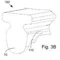
上記したように、ロータ20は、バケット10のダブテール60を受ける幾つかのスロット25を有することができる。同様に、バケット10の翼形部30は、ロータ20の回転によりガスストリームの運動エネルギーを機械エネルギーに変換するために高温ガスストリーム内に突出している。ダブテール60は、該ダブテールから延びる第1のタング又はタブ70及び第2のタブ80を含むことができる。ダブテール60のタブ70、80の端部間には、ギャップ90を形成することができる。あるタイプのシールシステムを使用しない限り、高圧冷却流が、このギャップ90を介して逸出するおそれがある。
As described above, the
図3A〜図6は、本明細書に記載したようなシールシステム100を示している。シールシステム100は、バケット10のダブテール60の第1のタブ70の周りにかつ該タブ70内に配置することができる。シールシステム100は、第1のタブ70内に配置されたシールスロット110を含むことができる。シールスロット110は、その全体又は一部が第1のタブ70の周辺の周りに延びることができる。シールスロット110は、その一側上にピボットポイント120を形成しまたその他側上にレストレッジ130を形成することができる。シールスロット110の寸法及び形状は、変化させることができる。シールスロット110は、従来型の機械加工法により形成することができる。本明細書では、その他のタイプの製造法もまた、使用することができる。シールシステム100はまた、第2のタブ80で使用することができ、またその他の場所で使用することができる。
3A-6 illustrate a
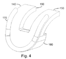
シールシステム100はまた、プレート140を含むことができる。プレート140は、シールスロット110内に配置することができる。プレート140は、通常の金属で製作することができる。プレート140は、全体としてシールスロット110の形状に一致するようなほぼ湾曲形状を有することができる。具体的には、プレート140は、ピボットポイント120とレストレッジ130との間で延びる2つの上部アーム150を形成している。以下により詳細に説明するように、シールスロット110は、該シールスロット内でプレート140が枢動することができるような、ピボットポイント120とレストレッジとの間での一定の曲がり量を有する。プレート140はさらに、2つの上部アーム150の下方にウェッジ160を形成する。ウェッジ160は、全体としてタブ70の寸法及び形状に一致している。
プレート140の1つの側面の周りに、ロープシール170を配置することができる。ロープシール170は、黒鉛ブレーデッド金属品及び同様なタイプの十分に変形可能な耐熱性材料で製作することができる。ロープシール170は、主として円形断面を有することができるが、本明細書では、その他のタイプの形状も使用することができる。同様に、本明細書では、その全体又は一部がプレート140にわたって延びるプレートシール並びにその他の構成を使用することができる。
A
図5に示すように、バケット10が静止状態にある時には、プレート140の上部アーム150は、タブ70のレストレッジ130上に載置される。上部アーム150とシールスロット110との間で、微小上方ギャップ180がピボットポイント近くまで延びる。同様に、ギャップ90が、タブ70とロータ20との間で延びる。
As shown in FIG. 5, when the
図6に示すように、バケット10の回転により、シールシステム100の周りに遠心力が生じる。具体的には、遠心力は、ピボットポイント120を中心にしてプレート140の上部アーム150を強制的に枢動させて、上方ギャップを閉鎖させる。そのようにすると、プレート140の上部アーム150とタブ70のレストレッジ130との間に、下方ギャップ190が形成される。同様に、プレート140は、ロープシール170を強制的にシールスロット110に当接させる。また、枢動することにより、プレート140のウェッジ160が強制的にギャップ90内に押し込まれて、該ギャップ90を閉鎖又は該ギャップ90の有効面積が少なくとも制限される。そのように枢動することにより、バケット10が全速又は高速状態にある時に、冷却供給空気がホイールスペースに漏洩するのが防止又は低減される。
As shown in FIG. 6, the rotation of the
従って、シールシステム100の使用は、ギャップ90を通しての漏洩を減少させる。従って、アルミニウム材料を使用せずに、通常使用のアルミニウム皮膜のシール性能と同様なシール性能を得ることができまたさらに改善することができる。従って、冷却流量が減少することにより、全体システム性能が高められる。シールシステム100は、その他のシールシステム及び方法で使用することができる。
Thus, use of the
以上の説明は本出願の一部の実施形態のみに関するものであること、並びに本明細書において当業者は、特許請求の範囲及びその均等物によって定まる本発明の一般的技術思想及び技術的範囲から逸脱せずに、多くの変更及び修正を行うことができることを理解されたい。 The above description relates only to some embodiments of the present application, and in this specification, those skilled in the art will understand from the general technical idea and technical scope of the present invention defined by the claims and their equivalents. It should be understood that many changes and modifications can be made without departing.
10 バケット
12 ロータ
25 スロット
30 翼形部
40 プラットフォーム
50 シャンク
60 ダブテール
65 シュラウド
70 第1のタブ
80 第2のタブ
90 ギャップ
100 ロープシール及びプレートシステム
110 シールスロット
120 ピボットポイント
130 レストレッジ
140 プレート
150 上部アーム
160 ウェッジ
170 シール
180 上方ギャップ
190 下方ギャップ
10 bucket 12 rotor 25
Claims (10)
前記ダブテールタブ(70)の周りに配置されかつピボットポイント(120)及びレストレッジ(130)を備えたシールスロット(110)と、
前記シールスロット(110)内に配置されたピボットプレート(140)と
を備えていて、前記ピボットプレート(140)が、前記バケット(10)が回転している時に前記ピボットポイント(120)を中心にしてかつ前記ギャップ(90)内に枢動する、シールシステム(100)。 A sealing system (100) for sealing a gap (90) between a dovetail tab (70) of a bucket (10) and a rotor (20),
A seal slot (110) disposed about the dovetail tab (70) and comprising a pivot point (120) and a restledge (130);
A pivot plate (140) disposed in the seal slot (110), the pivot plate (140) being centered on the pivot point (120) when the bucket (10) is rotating. A seal system (100) that pivots into the gap (90).
前記ダブテールタブ(70)のシールスロット(110)内にピボットプレート(140)を配置するステップと、
前記バケット(10)を回転させるステップと、
遠心力下で前記ピボットプレート(140)を前記ギャップ(90)内に枢動させるステップと
を含む方法。 A method of sealing a gap (90) between a dovetail tab (70) of a bucket (10) and a rotor (20), comprising:
Placing a pivot plate (140) in a seal slot (110) of the dovetail tab (70);
Rotating the bucket (10);
Pivoting the pivot plate (140) into the gap (90) under centrifugal force.
Applications Claiming Priority (2)
| Application Number | Priority Date | Filing Date | Title |
|---|---|---|---|
| US12/168,929 US8011894B2 (en) | 2008-07-08 | 2008-07-08 | Sealing mechanism with pivot plate and rope seal |
| US12/168,929 | 2008-07-08 |
Publications (2)
| Publication Number | Publication Date |
|---|---|
| JP2010019254A true JP2010019254A (en) | 2010-01-28 |
| JP5507906B2 JP5507906B2 (en) | 2014-05-28 |
Family
ID=41413003
Family Applications (1)
| Application Number | Title | Priority Date | Filing Date |
|---|---|---|---|
| JP2009154500A Active JP5507906B2 (en) | 2008-07-08 | 2009-06-30 | Seal mechanism with pivot plate and rope seal |
Country Status (5)
| Country | Link |
|---|---|
| US (1) | US8011894B2 (en) |
| JP (1) | JP5507906B2 (en) |
| CN (1) | CN101624918A (en) |
| DE (1) | DE102009026057A1 (en) |
| FR (1) | FR2933731B1 (en) |
Cited By (1)
| Publication number | Priority date | Publication date | Assignee | Title |
|---|---|---|---|---|
| JP2018529877A (en) * | 2015-09-04 | 2018-10-11 | アンサルド エネルジア アイ・ピー ユー・ケイ リミテッドAnsaldo Energia Ip Uk Limited | Flow control device for rotating flow supply system |
Families Citing this family (8)
| Publication number | Priority date | Publication date | Assignee | Title |
|---|---|---|---|---|
| US8602737B2 (en) * | 2010-06-25 | 2013-12-10 | General Electric Company | Sealing device |
| US8985960B2 (en) * | 2011-03-30 | 2015-03-24 | General Electric Company | Method and system for sealing a dovetail |
| US20130330184A1 (en) * | 2012-06-08 | 2013-12-12 | General Electric Company | Aerodynamic element of turbine engine |
| US9175573B2 (en) * | 2012-11-28 | 2015-11-03 | General Electric Company | Dovetail attachment seal for a turbomachine |
| DE102018209587B4 (en) * | 2017-07-14 | 2021-06-24 | Siemens Energy Global GmbH & Co. KG | Rotor with pendulum element |
| EP3438410B1 (en) | 2017-08-01 | 2021-09-29 | General Electric Company | Sealing system for a rotary machine |
| US11441440B2 (en) * | 2020-04-27 | 2022-09-13 | Raytheon Technologies Corporation | Rotor assembly |
| CN113623020B (en) * | 2021-08-02 | 2022-07-08 | 无锡友鹏航空装备科技有限公司 | Turbine guider that leakproofness is high |
Citations (3)
| Publication number | Priority date | Publication date | Assignee | Title |
|---|---|---|---|---|
| JPH108908A (en) * | 1996-04-02 | 1998-01-13 | Europ Gas Turbines Ltd | Turbo machine |
| JPH1030405A (en) * | 1996-07-18 | 1998-02-03 | Toshiba Corp | Cooling device for turbine moving blade |
| JP2004190680A (en) * | 2002-12-11 | 2004-07-08 | General Electric Co <Ge> | Sealing of steam turbine bucket hook leakage using braided rope |
Family Cites Families (21)
| Publication number | Priority date | Publication date | Assignee | Title |
|---|---|---|---|---|
| US3023998A (en) * | 1959-03-13 | 1962-03-06 | Jr Walter H Sanderson | Rotor blade retaining device |
| US3709631A (en) | 1971-03-18 | 1973-01-09 | Caterpillar Tractor Co | Turbine blade seal arrangement |
| FR2517779B1 (en) | 1981-12-03 | 1986-06-13 | Snecma | DEVICE FOR DAMPING THE BLADES OF A TURBOMACHINE BLOWER |
| US4422827A (en) | 1982-02-18 | 1983-12-27 | United Technologies Corporation | Blade root seal |
| US4480957A (en) | 1983-04-14 | 1984-11-06 | General Electric Company | Dynamic response modification and stress reduction in dovetail and blade assembly |
| US4743166A (en) | 1984-12-20 | 1988-05-10 | General Electric Company | Blade root seal |
| US4743164A (en) | 1986-12-29 | 1988-05-10 | United Technologies Corporation | Interblade seal for turbomachine rotor |
| US4725200A (en) | 1987-02-24 | 1988-02-16 | Westinghouse Electric Corp. | Apparatus and method for reducing relative motion between blade and rotor in steam turbine |
| FR2639063A1 (en) | 1988-11-17 | 1990-05-18 | Snecma | STOP AND SEGMENT SEGMENT OF A SET OF AUBES MOUNTED ON A TURBOMACHINE ROTOR DISK |
| GB2228541B (en) | 1989-02-23 | 1993-04-14 | Rolls Royce Plc | Device for damping vibrations in turbomachinery blades |
| US5139389A (en) | 1990-09-14 | 1992-08-18 | United Technologies Corporation | Expandable blade root sealant |
| US5256035A (en) * | 1992-06-01 | 1993-10-26 | United Technologies Corporation | Rotor blade retention and sealing construction |
| US5257909A (en) | 1992-08-17 | 1993-11-02 | General Electric Company | Dovetail sealing device for axial dovetail rotor blades |
| US5228835A (en) | 1992-11-24 | 1993-07-20 | United Technologies Corporation | Gas turbine blade seal |
| FR2726323B1 (en) | 1994-10-26 | 1996-12-13 | Snecma | ASSEMBLY OF A ROTARY DISC AND BLADES, ESPECIALLY USED IN A TURBOMACHINE |
| US6273683B1 (en) | 1999-02-05 | 2001-08-14 | Siemens Westinghouse Power Corporation | Turbine blade platform seal |
| US6565322B1 (en) | 1999-05-14 | 2003-05-20 | Siemens Aktiengesellschaft | Turbo-machine comprising a sealing system for a rotor |
| JP2002544430A (en) * | 1999-05-14 | 2002-12-24 | シーメンス アクチエンゲゼルシヤフト | Fluid machinery with leak-proof device for rotor, especially gas turbine |
| DE50009870D1 (en) | 1999-06-07 | 2005-04-28 | Siemens Ag | FLOW MACHINE AND SEALING ELEMENT FOR A ROTOR OF A FLOW MACHINE |
| US6296172B1 (en) | 2000-03-28 | 2001-10-02 | General Electric Company | Method of sealing disk slots for turbine bucket dovetails |
| US6375429B1 (en) | 2001-02-05 | 2002-04-23 | General Electric Company | Turbomachine blade-to-rotor sealing arrangement |
-
2008
- 2008-07-08 US US12/168,929 patent/US8011894B2/en active Active
-
2009
- 2009-06-11 FR FR0953897A patent/FR2933731B1/en not_active Expired - Fee Related
- 2009-06-29 DE DE102009026057A patent/DE102009026057A1/en active Pending
- 2009-06-30 JP JP2009154500A patent/JP5507906B2/en active Active
- 2009-07-08 CN CN200910151409.2A patent/CN101624918A/en active Pending
Patent Citations (3)
| Publication number | Priority date | Publication date | Assignee | Title |
|---|---|---|---|---|
| JPH108908A (en) * | 1996-04-02 | 1998-01-13 | Europ Gas Turbines Ltd | Turbo machine |
| JPH1030405A (en) * | 1996-07-18 | 1998-02-03 | Toshiba Corp | Cooling device for turbine moving blade |
| JP2004190680A (en) * | 2002-12-11 | 2004-07-08 | General Electric Co <Ge> | Sealing of steam turbine bucket hook leakage using braided rope |
Cited By (1)
| Publication number | Priority date | Publication date | Assignee | Title |
|---|---|---|---|---|
| JP2018529877A (en) * | 2015-09-04 | 2018-10-11 | アンサルド エネルジア アイ・ピー ユー・ケイ リミテッドAnsaldo Energia Ip Uk Limited | Flow control device for rotating flow supply system |
Also Published As
| Publication number | Publication date |
|---|---|
| FR2933731A1 (en) | 2010-01-15 |
| US8011894B2 (en) | 2011-09-06 |
| FR2933731B1 (en) | 2014-12-26 |
| JP5507906B2 (en) | 2014-05-28 |
| CN101624918A (en) | 2010-01-13 |
| DE102009026057A1 (en) | 2010-01-14 |
| US20100008769A1 (en) | 2010-01-14 |
Similar Documents
| Publication | Publication Date | Title |
|---|---|---|
| JP5507906B2 (en) | Seal mechanism with pivot plate and rope seal | |
| JP2010019255A (en) | Compliant seal for rotor slot | |
| JP5312863B2 (en) | Pressing plate seal | |
| JP2010019261A (en) | Spring seal for turbine dovetail | |
| US7686571B1 (en) | Bladed rotor with shear pin attachment | |
| JP5329334B2 (en) | Vibration damper | |
| US8845284B2 (en) | Apparatus and system for sealing a turbine rotor | |
| JP5405215B2 (en) | Method and apparatus for forming seal slots for turbine components | |
| JP2007120501A (en) | Interstage seal, turbine blade, and interface seal between cooled rotor and stator of gas turbine engine | |
| US8827643B2 (en) | Turbine bucket platform leading edge scalloping for performance and secondary flow and related method | |
| JP2008291846A (en) | Method for centrally installing cutter tooth on turbine blade with shroud | |
| US20130108451A1 (en) | Turbine bucket angel wing features for forward cavity flow control and related method | |
| JP2006342796A (en) | Seal assembly of gas turbine engine, rotor assembly and blade for rotor assembly | |
| JP2013151936A (en) | Retrofittable interstage angled seal | |
| JP5400500B2 (en) | Labyrinth seal for turbine dovetail | |
| JP5911684B2 (en) | Turbine blade platform cooling system | |
| JP2010019258A (en) | Gas pressure assisted seal | |
| US20170370230A1 (en) | Blade platform cooling in a gas turbine | |
| US20180156046A1 (en) | Rotor blade for a gas turbine | |
| JP2021099095A (en) | Improved rotor blade sealing structures |
Legal Events
| Date | Code | Title | Description |
|---|---|---|---|
| A621 | Written request for application examination |
Free format text: JAPANESE INTERMEDIATE CODE: A621 Effective date: 20120625 |
|
| A977 | Report on retrieval |
Free format text: JAPANESE INTERMEDIATE CODE: A971007 Effective date: 20130725 |
|
| A131 | Notification of reasons for refusal |
Free format text: JAPANESE INTERMEDIATE CODE: A131 Effective date: 20130806 |
|
| A602 | Written permission of extension of time |
Free format text: JAPANESE INTERMEDIATE CODE: A602 Effective date: 20131108 |
|
| A521 | Request for written amendment filed |
Free format text: JAPANESE INTERMEDIATE CODE: A523 Effective date: 20140205 |
|
| TRDD | Decision of grant or rejection written | ||
| A01 | Written decision to grant a patent or to grant a registration (utility model) |
Free format text: JAPANESE INTERMEDIATE CODE: A01 Effective date: 20140225 |
|
| A61 | First payment of annual fees (during grant procedure) |
Free format text: JAPANESE INTERMEDIATE CODE: A61 Effective date: 20140320 |
|
| R150 | Certificate of patent or registration of utility model |
Ref document number: 5507906 Country of ref document: JP Free format text: JAPANESE INTERMEDIATE CODE: R150 |
|
| R250 | Receipt of annual fees |
Free format text: JAPANESE INTERMEDIATE CODE: R250 |
|
| R250 | Receipt of annual fees |
Free format text: JAPANESE INTERMEDIATE CODE: R250 |
|
| R250 | Receipt of annual fees |
Free format text: JAPANESE INTERMEDIATE CODE: R250 |
|
| R250 | Receipt of annual fees |
Free format text: JAPANESE INTERMEDIATE CODE: R250 |
|
| R250 | Receipt of annual fees |
Free format text: JAPANESE INTERMEDIATE CODE: R250 |
|
| R250 | Receipt of annual fees |
Free format text: JAPANESE INTERMEDIATE CODE: R250 |
|
| R250 | Receipt of annual fees |
Free format text: JAPANESE INTERMEDIATE CODE: R250 |
|
| S111 | Request for change of ownership or part of ownership |
Free format text: JAPANESE INTERMEDIATE CODE: R313113 |
|
| R350 | Written notification of registration of transfer |
Free format text: JAPANESE INTERMEDIATE CODE: R350 |
|
| R250 | Receipt of annual fees |
Free format text: JAPANESE INTERMEDIATE CODE: R250 |