JP2010019213A - Fuel injection device - Google Patents
Fuel injection device Download PDFInfo
- Publication number
- JP2010019213A JP2010019213A JP2008182372A JP2008182372A JP2010019213A JP 2010019213 A JP2010019213 A JP 2010019213A JP 2008182372 A JP2008182372 A JP 2008182372A JP 2008182372 A JP2008182372 A JP 2008182372A JP 2010019213 A JP2010019213 A JP 2010019213A
- Authority
- JP
- Japan
- Prior art keywords
- pressure
- pressure chamber
- fuel
- damper
- chamber
- Prior art date
- Legal status (The legal status is an assumption and is not a legal conclusion. Google has not performed a legal analysis and makes no representation as to the accuracy of the status listed.)
- Granted
Links
- 239000000446 fuel Substances 0.000 title claims abstract description 196
- 238000002347 injection Methods 0.000 title claims abstract description 111
- 239000007924 injection Substances 0.000 title claims abstract description 111
- 230000008859 change Effects 0.000 claims abstract description 19
- 230000007423 decrease Effects 0.000 claims description 17
- 230000004044 response Effects 0.000 abstract description 12
- 238000003825 pressing Methods 0.000 abstract description 2
- 239000000243 solution Substances 0.000 abstract 1
- 238000002485 combustion reaction Methods 0.000 description 11
- 230000001174 ascending effect Effects 0.000 description 9
- 238000010586 diagram Methods 0.000 description 5
- 230000004308 accommodation Effects 0.000 description 3
- 238000006073 displacement reaction Methods 0.000 description 3
- 238000009825 accumulation Methods 0.000 description 2
- 230000009471 action Effects 0.000 description 2
- 230000003247 decreasing effect Effects 0.000 description 2
- 230000000630 rising effect Effects 0.000 description 2
- 239000007921 spray Substances 0.000 description 2
- 238000000889 atomisation Methods 0.000 description 1
- 230000000052 comparative effect Effects 0.000 description 1
- 230000003111 delayed effect Effects 0.000 description 1
- 230000006866 deterioration Effects 0.000 description 1
- 230000000694 effects Effects 0.000 description 1
- 238000009434 installation Methods 0.000 description 1
- 230000002452 interceptive effect Effects 0.000 description 1
- 238000000034 method Methods 0.000 description 1
- 230000004048 modification Effects 0.000 description 1
- 238000012986 modification Methods 0.000 description 1
Images


Classifications
-
- F—MECHANICAL ENGINEERING; LIGHTING; HEATING; WEAPONS; BLASTING
- F02—COMBUSTION ENGINES; HOT-GAS OR COMBUSTION-PRODUCT ENGINE PLANTS
- F02M—SUPPLYING COMBUSTION ENGINES IN GENERAL WITH COMBUSTIBLE MIXTURES OR CONSTITUENTS THEREOF
- F02M51/00—Fuel-injection apparatus characterised by being operated electrically
- F02M51/06—Injectors peculiar thereto with means directly operating the valve needle
- F02M51/0603—Injectors peculiar thereto with means directly operating the valve needle using piezoelectric or magnetostrictive operating means
-
- F—MECHANICAL ENGINEERING; LIGHTING; HEATING; WEAPONS; BLASTING
- F02—COMBUSTION ENGINES; HOT-GAS OR COMBUSTION-PRODUCT ENGINE PLANTS
- F02M—SUPPLYING COMBUSTION ENGINES IN GENERAL WITH COMBUSTIBLE MIXTURES OR CONSTITUENTS THEREOF
- F02M2200/00—Details of fuel-injection apparatus, not otherwise provided for
- F02M2200/31—Fuel-injection apparatus having hydraulic pressure fluctuations damping elements
-
- F—MECHANICAL ENGINEERING; LIGHTING; HEATING; WEAPONS; BLASTING
- F02—COMBUSTION ENGINES; HOT-GAS OR COMBUSTION-PRODUCT ENGINE PLANTS
- F02M—SUPPLYING COMBUSTION ENGINES IN GENERAL WITH COMBUSTIBLE MIXTURES OR CONSTITUENTS THEREOF
- F02M2200/00—Details of fuel-injection apparatus, not otherwise provided for
- F02M2200/70—Linkage between actuator and actuated element, e.g. between piezoelectric actuator and needle valve or pump plunger
- F02M2200/703—Linkage between actuator and actuated element, e.g. between piezoelectric actuator and needle valve or pump plunger hydraulic
- F02M2200/704—Linkage between actuator and actuated element, e.g. between piezoelectric actuator and needle valve or pump plunger hydraulic with actuator and actuated element moving in different directions, e.g. in opposite directions
-
- F—MECHANICAL ENGINEERING; LIGHTING; HEATING; WEAPONS; BLASTING
- F02—COMBUSTION ENGINES; HOT-GAS OR COMBUSTION-PRODUCT ENGINE PLANTS
- F02M—SUPPLYING COMBUSTION ENGINES IN GENERAL WITH COMBUSTIBLE MIXTURES OR CONSTITUENTS THEREOF
- F02M61/00—Fuel-injectors not provided for in groups F02M39/00 - F02M57/00 or F02M67/00
- F02M61/16—Details not provided for in, or of interest apart from, the apparatus of groups F02M61/02 - F02M61/14
- F02M61/20—Closing valves mechanically, e.g. arrangements of springs or weights or permanent magnets; Damping of valve lift
- F02M61/205—Means specially adapted for varying the spring tension or assisting the spring force to close the injection-valve, e.g. with damping of valve lift
Landscapes
- Engineering & Computer Science (AREA)
- Chemical & Material Sciences (AREA)
- Combustion & Propulsion (AREA)
- Mechanical Engineering (AREA)
- General Engineering & Computer Science (AREA)
- Fuel-Injection Apparatus (AREA)
Abstract
Description
本発明は、内燃機関に燃料を噴射供給する燃料噴射装置に関し、特に、加圧した燃料でニードルによる噴孔の開閉を制御する燃料噴射装置に関する。 The present invention relates to a fuel injection device that injects and supplies fuel to an internal combustion engine, and more particularly to a fuel injection device that controls opening and closing of an injection hole by a needle with pressurized fuel.
従来、内燃機関の燃焼室に燃料を噴射供給する燃料噴射装置が知られている。
例えば、特許文献1によると、ピストンにて内部の燃料が加圧され当該燃料の圧力によりニードルを押し上げる圧力室を有してなる圧力制御部を備え、ニードルで噴孔を開閉して燃料を断続的に噴射する燃料噴射装置が公知である。このような燃料噴射装置は、特に、気筒内に直接燃料が噴射される筒内直噴型内燃機関、例えばディーゼル内燃機関などにおいて、燃料噴射圧を高圧化して噴霧の微粒化を促進するというニーズに対応している。
Conventionally, a fuel injection device that injects and supplies fuel to a combustion chamber of an internal combustion engine is known.
For example, according to
ここで、特許文献1に開示された燃料噴射装置は、駆動力の大きなアクチュエータ、例えばピエゾ駆動体によりピストンを変位させることで、燃料噴射圧に相当する燃料通路内の圧力に対して圧力室の圧力を相対的に高め、燃料噴射圧が高圧の条件下で燃料の噴射量を制御しようとするものである。しかしながら、加圧された燃料でニードルを押し上げる方法には、ニードルの上昇に伴い圧力室の容積が増加するため、圧力室の圧力低下によってニードルの上昇速度がすぐに低下してしまうという欠点があった。
Here, the fuel injection device disclosed in
この場合、噴孔を開放した直後のニードルが上昇速度を維持できず、圧力室の圧力が燃料通路内の圧力などの噴孔を閉塞する方向への付勢力に抗してニードルを押し上げ噴孔を開放するのに最低限必要な圧力(以下、「必要開弁圧」という)に保たれていないと、ニードルが徐々に下がっておのずと噴孔を閉じてしまうことが問題になる。この状態が生じると、アクチュエータに燃料噴射を行うための噴射信号が入力されたままであるにもかかわらず、噴孔がニードルによってすぐに閉ざされ燃料噴射が終了してしまうので、当該噴射信号に基づいて燃料噴射量を制御することが困難になる。したがって、上述したような従来の燃料噴射装置では、安定した開弁作動応答が得られないことが懸念される。 In this case, the needle immediately after opening the nozzle hole cannot maintain the rising speed, and the pressure in the pressure chamber pushes up the needle against the urging force in the direction of closing the nozzle hole, such as the pressure in the fuel passage. If the minimum pressure required to open the nozzle (hereinafter referred to as “required valve opening pressure”) is not maintained, the needle will gradually drop and the nozzle hole will be closed. When this state occurs, the injection hole is immediately closed by the needle and the fuel injection ends even though the injection signal for performing the fuel injection is still input to the actuator. Therefore, it becomes difficult to control the fuel injection amount. Therefore, there is a concern that the conventional fuel injection device as described above cannot obtain a stable valve opening response.
よって、本発明の目的は、開弁作動時におけるニードルの上昇速度を維持し、安定した作動応答にて燃料噴射を制御する燃料噴射装置を提供することにある。 Therefore, an object of the present invention is to provide a fuel injection device that maintains the needle ascending speed during valve opening operation and controls fuel injection with a stable operation response.
請求項1に記載の発明によると、ノズルボディ内部の燃料通路に外部から燃料が供給され、当該燃料通路の下流でニードルにて開閉される噴孔から燃料噴射を行う燃料噴射装置において、内部の燃料を加圧手段にて加圧されることによりニードルを噴孔の開放方向へ付勢する圧力室を有する圧力制御部が備わっており、本発明では、この圧力制御部にダンパを設けたことを技術的特徴としている。このダンパは、圧力室の圧力が上昇すると作動し、その作動によって当該圧力室における圧力の変化を緩和するよう構成されている。
従来の燃料噴射装置におけるニードルの上昇速度が開弁作動後すぐに低下するという問題は、圧力室の圧力が短時間で低下することに起因するものである。ここで、本発明によると、例えば、圧力室の加圧行程では内部の燃料が必要開弁圧を超えて加圧される余剰の圧力を減少させるようにダンパが作動し、ニードルの上昇に伴い圧力室の圧力が低下する際には当該ダンパが圧力室における圧力の低下速度を緩めるように圧力制御部が構成されている。このように、圧力制御部にダンパを構成要素として加え、当該ダンパの作用により圧力室における単位時間あたりの圧力低下の度合いを小さく抑えるようにすれば、燃料噴射装置の開弁作動時におけるニードルの上昇速度を維持し、安定した作動応答にて燃料噴射を制御することができる。
According to the first aspect of the present invention, in the fuel injection device in which fuel is supplied from the outside to the fuel passage inside the nozzle body and fuel is injected from the nozzle hole opened and closed by the needle downstream of the fuel passage, A pressure control unit having a pressure chamber for urging the needle in the opening direction of the nozzle hole by pressurizing the fuel by the pressurizing means is provided. In the present invention, a damper is provided in the pressure control unit. Is a technical feature. The damper is configured to operate when the pressure in the pressure chamber increases, and to reduce a change in pressure in the pressure chamber by the operation.
The problem that the ascending speed of the needle in the conventional fuel injection device decreases immediately after the valve opening operation is caused by the pressure in the pressure chamber decreasing in a short time. Here, according to the present invention, for example, in the pressurization stroke of the pressure chamber, the damper operates so as to reduce the excess pressure in which the internal fuel exceeds the required valve opening pressure, and as the needle rises, When the pressure in the pressure chamber decreases, the pressure control unit is configured so that the damper slows down the pressure decrease rate in the pressure chamber. In this way, if a damper is added as a component to the pressure control unit so that the degree of pressure drop per unit time in the pressure chamber is suppressed by the action of the damper, the needle of the fuel injection device during valve opening operation can be reduced. The fuel injection can be controlled with a stable operation response while maintaining the rising speed.
請求項2に記載の発明によると、上述したダンパを、圧力室の容積を調整することによって当該圧力室の圧力変化を緩和するものとして構成したところに特徴がある。つまり、圧力室の圧力が上昇すると、当該圧力室の圧力が必要開弁圧を超えて加圧される圧力のロスを、ダンパが圧力室の容積を増加させるよう作動することにより低減させるのである。そして、ニードルの上昇時において圧力が低下するとき、ダンパの作動により一旦増加した圧力室の容積を再び減少させ、当該圧力室の圧力低下の速度を緩めるように当該ダンパが作動前の初期状態に復帰していくので、圧力室の容積変化および圧力変化の幅が小さくなる。このように、圧力室の容積変化を緩和することで圧力変化を緩和するようダンパを機能させれば、当該圧力室の圧力低下に起因するニードルの上昇速度の低下を防ぐことができる。これにより、開弁作動時におけるニードルの上昇速度を維持し、安定した作動応答にて燃料噴射を制御する燃料噴射装置が得られる。
The invention according to
請求項3に記載の発明によると、ダンパ通路を圧力室に接続するように設け、当該ダンパ通路にダンパを設置することにより、圧力室は、その外部からダンパの作用を受けてその内部における圧力変化を調整されるように構成されるものとなりうる。ここで、圧力室の内部にダンパを設置するのであれば、当該圧力室の内部における燃料の流れを妨げないように当該ダンパを構成する必要が生じる。そこで、ダンパの設置箇所を圧力室に通ずるよう別途設けられたダンパ通路とすれば、圧力室にて加圧される燃料の流れ、または、圧力室を形成する各壁面に干渉することなくダンパを構成することができる。また、例えば、ダンパが圧力室の容積変化を調整するものである場合、ダンパ通路内部の容積を圧力室の容積の一部として当該ダンパ通路内部の容積を変化させることになる。この構成によると、圧力室の容積をその外部に拡張させ、圧力低下に従って当該拡張させた容積を再び縮小させることにより、容易にその圧力変化を緩和することができる。したがって、圧力制御部にダンパを設けることが容易になり、開弁作動時におけるニードルの上昇速度を維持し、安定した作動応答にて燃料噴射を制御する燃料噴射装置を提供することができる。 According to the third aspect of the present invention, the damper passage is provided so as to be connected to the pressure chamber, and the damper is installed in the damper passage, so that the pressure chamber receives the action of the damper from the outside, and the pressure in the inside thereof It can be configured to adjust for changes. Here, if a damper is installed inside the pressure chamber, it is necessary to configure the damper so as not to hinder the flow of fuel inside the pressure chamber. Therefore, if a damper passage is provided separately so that the installation location of the damper communicates with the pressure chamber, the damper can be installed without interfering with the flow of fuel pressurized in the pressure chamber or each wall surface forming the pressure chamber. Can be configured. For example, when the damper adjusts the volume change of the pressure chamber, the volume inside the damper passage is changed with the volume inside the damper passage as a part of the volume of the pressure chamber. According to this configuration, the pressure change can be easily relaxed by expanding the volume of the pressure chamber to the outside and reducing the expanded volume again according to the pressure drop. Accordingly, it is easy to provide a damper in the pressure control unit, and it is possible to provide a fuel injection device that maintains the needle ascending speed during valve opening operation and controls fuel injection with a stable operation response.
請求項4に記載の発明によると、圧力制御部にて制御されるニードルにより噴孔が開閉される行程は、具体的には、以下の構成の作動に例示される。まず、ノズルボディの内壁にて構成されニードルを収容している空間は、当該ニードルの大径部を挟んで圧力室およびその反対側の背圧室となっている。背圧室は燃料通路に連通し、その内部の燃料の圧力が高まるとニードルを噴孔の閉塞方向へ付勢する。このため、ニードルは大径部を押圧する圧力室からの圧力と背圧室からの圧力との圧力差により、ノズルボディ内部を往復摺動させられることにより噴孔を開閉する。ここで、燃料通路の内部の燃料圧力自体が高まった場合には、必要開弁圧も高まり、圧力室内における燃料の圧力が加圧手段により高められて当該必要開弁圧に到達すると、ニードルが上昇し始める。また、ニードルは圧力室の圧力が十分に低下すると、背圧室の圧力により噴孔を閉塞する方向へ付勢される。このように、燃料通路の圧力に関わらずニードルの移動を制御可能に構成された圧力制御部を備えた燃料噴射装置は、上述のダンパを設けることにより、開弁作動時におけるニードルの上昇速度を維持できるようになるので、安定した作動応答にて燃料噴射を制御することができる。 According to the fourth aspect of the present invention, the stroke in which the nozzle hole is opened and closed by the needle controlled by the pressure control unit is specifically exemplified by the operation of the following configuration. First, the space configured by the inner wall of the nozzle body and containing the needle is a pressure chamber and a back pressure chamber on the opposite side across the large diameter portion of the needle. The back pressure chamber communicates with the fuel passage, and urges the needle in the closing direction of the nozzle hole when the pressure of the fuel inside thereof increases. For this reason, the needle opens and closes the nozzle hole by reciprocatingly sliding inside the nozzle body due to the pressure difference between the pressure from the pressure chamber pressing the large diameter portion and the pressure from the back pressure chamber. Here, when the fuel pressure itself in the fuel passage increases, the required valve opening pressure also increases. When the fuel pressure in the pressure chamber is increased by the pressurizing means and reaches the required valve opening pressure, the needle Begins to rise. Further, when the pressure in the pressure chamber is sufficiently lowered, the needle is biased in the direction of closing the nozzle hole by the pressure in the back pressure chamber. As described above, the fuel injection device including the pressure control unit configured to be able to control the movement of the needle regardless of the pressure in the fuel passage is provided with the above-described damper, thereby increasing the ascending speed of the needle during the valve opening operation. As a result, the fuel injection can be controlled with a stable operation response.
請求項5に記載の発明によると、圧力室と背圧室との圧力差でニードルの移動を制御する圧力制御部にダンパを設けるのであれば、具体的には以下の構成を適用することが例示される。上述したダンパは、圧力室と燃料通路とを連通するダンパ通路に、当該ダンパ通路内を摺動可能なピストンとして設けるのが望ましい。ここで、ピストンとして構成されるダンパは、例えば、圧力室と背圧室との圧力差が所定値以上になると、圧力室の容積を増加させる方向、すなわち背圧室側へ移動する。そして、ニードルが上昇するにつれて、圧力室の容積を減少させる方向、すなわち圧力室側へ移動していくので、結果として圧力室の容積が短時間で大きく変動するのを防ぎ、圧力室の圧力変化を緩和することができる。これにより、開弁作動時におけるニードルの上昇速度を維持し、安定した作動応答にて燃料噴射を制御する燃料噴射装置を提供することができる。 According to the fifth aspect of the present invention, if the damper is provided in the pressure control unit that controls the movement of the needle by the pressure difference between the pressure chamber and the back pressure chamber, specifically, the following configuration can be applied. Illustrated. The above-described damper is desirably provided as a piston that can slide in the damper passage in the damper passage that connects the pressure chamber and the fuel passage. Here, for example, when the pressure difference between the pressure chamber and the back pressure chamber becomes equal to or greater than a predetermined value, the damper configured as a piston moves in the direction of increasing the volume of the pressure chamber, that is, toward the back pressure chamber. As the needle moves up, the pressure chamber volume decreases, that is, moves toward the pressure chamber side. As a result, the pressure chamber volume is prevented from changing greatly in a short time, and the pressure chamber pressure change Can be relaxed. Accordingly, it is possible to provide a fuel injection device that maintains the needle ascending speed during the valve opening operation and controls the fuel injection with a stable operation response.
なお、以上説明した請求項1から5のいずれか一項に記載の発明を実施するにあたって、より具体的には、以下のように構成された燃料噴射装置として本発明を具現化することが考えられる。請求項6に記載の発明によると、燃料噴射装置は、内部に燃料通路を形成するとともにその下流に噴孔を形成するノズルボディ、当該ノズルボディの内部を往復移動することによって噴孔の開閉を行うニードル、そして内部の燃料の圧力によりニードルを噴孔の開放方向へ付勢する圧力室を有する圧力制御部に加え、一端がノズルボディの内壁に取り付けられ他端が噴孔の閉塞方向へ向けてニードルを付勢する第1付勢部材を備えている。したがって、圧力制御部は、圧力室の圧力を高められることで、第1付勢部材の付勢力に抗してニードルを押し上げ噴孔を開放するよう作用するものとなる。また、この燃料噴射装置は、圧力室の圧力を変化させる加圧ピストン、当該加圧ピストンを圧力室の圧力が低下する方向に付勢する第2付勢部材、および当該加圧ピストンを第2付勢部材の付勢力に抗して押圧するピエゾ駆動体を備えている。このピエゾ駆動体は、ノズルボディに一端が固定され、通電量に応じて伸長することで圧力室の圧力を上昇させる方向に加圧ピストンを押圧するものである。本発明においては、上記の構成を備えてなる燃料噴射装置の圧力制御部に、圧力室の圧力の上昇に伴い作動するダンパを設け、このダンパの作動により当該圧力室の容積を増加させることで圧力変化を緩和する。
In carrying out the invention according to any one of
すなわち、本発明では、圧力室の内部の燃料を加圧する加圧手段を駆動力の大きなピエゾ駆動体により駆動される加圧ピストンにて構成し、加圧ピストンおよびニードルのそれぞれに対して付勢部材を設けるのである。これにより、圧力室の圧力が低下する方向に加圧ピストンを付勢し、噴孔の閉塞方向へニードルを付勢する機械的な作動により燃料噴射を制御する簡易な燃料噴射装置に、ダンパにより圧力室の圧力変化を緩和する機能を加えることができる。したがって、燃料噴射装置の上述した機械的な作動において、ダンパによりニードルの上昇速度を維持するよう制御する効果が得られ、安定した作動応答にて燃料噴射の制御を行うことができる。なお、請求項7から9に記載の発明によると、上述した請求項6に係る燃料噴射装置の発明は、さらに請求項3から5に記載された発明と同様の構成を備えるものとして具現化されていてもよい。
That is, in the present invention, the pressurizing means for pressurizing the fuel inside the pressure chamber is constituted by a pressurizing piston driven by a piezoelectric driving body having a large driving force, and urges each of the pressurizing piston and the needle. A member is provided. As a result, a damper is added to a simple fuel injection device that controls fuel injection by a mechanical operation that urges the pressurizing piston in the direction in which the pressure in the pressure chamber decreases and urges the needle in the closing direction of the nozzle hole. A function to alleviate the pressure change in the pressure chamber can be added. Therefore, in the above-described mechanical operation of the fuel injection device, an effect of controlling the needle ascending speed by the damper is obtained, and the fuel injection can be controlled with a stable operation response. According to the invention described in
以下、本発明に係る実施形態を図面に基づき説明する。
(第1実施形態)
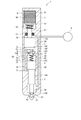
本発明の第1実施形態による燃料噴射装置を図1に示す。燃料噴射装置1は、例えばディーゼル内燃機関の各気筒に取り付けられ、コモンレールに蓄圧状態で蓄えられた高圧の燃料を各気筒に噴射する。燃料噴射装置1は、ノズルボディ2、ニードル3、加圧ピストン5、およびピエゾ駆動体9等を備えている。ノズルボディ2は、筒状に形成され、一方の端部に噴孔21が形成されている。噴孔21は、ノズルボディ2の内部と外部を連通している。また、ノズルボディ2は、その内部で噴孔21と連通する空間として燃料室101を形成する。
Embodiments according to the present invention will be described below with reference to the drawings.
(First embodiment)
A fuel injection device according to a first embodiment of the present invention is shown in FIG. The
ノズルボディ2の内部には、燃料通路100が形成されている。燃料通路100は、ノズルボディ2に形成された流入口22を経由して蓄圧室4に連通している。蓄圧室4は、例えば、ディーゼル内燃機関のコモンレールである。燃料通路100には、蓄圧室4の内部と概ね同一の圧力の燃料が供給される。なお、燃料室101は、燃料通路100の一部を構成している。
A
ノズルボディ2の内部において、燃料通路100は燃料室101に連通する燃料溜り室102、ニードル3の大径部30を収容するニードル室103、ニードル3の小径部31を収容する摺動室104、および加圧ピストン5を構成するピストン50を収容するピストン室105に連通している。ニードル室103は、摺動室104を介して燃料溜り室102に連通する。ニードル3は、径が大小に異なる略円柱状の大径部30および小径部31、ならびに、小径部31よりも径が小さく、大径部30の反対側へ小径部31から延びている弁部32から構成される。ニードル3は、その大径部30がニードル室103の内壁に摺動し小径部31が摺動室104の内壁に摺動するとともに、弁部32が燃料溜り室102内を往復移動するよう、ノズルボディ2の内部に配置されている。ニードル3の大径部30は、ニードル室103の反噴孔21側で対向する内壁との間に設けられた第1付勢部材33により、噴孔21側へ付勢されている。また、弁部32は、ノズルボディ2の内壁で燃料室101と燃料溜り室102との間に形成された弁座23に当接し、燃料通路100のノズルボディ2内部側とノズルボディ2外部とを遮断している。
Inside the
加圧手段としての加圧ピストン5は、ピストン室105の内壁に摺動するピストン50の反噴孔21側に延びるロッド部51、および当該ロッド部を挟んでピストン50の反対側に接続されたフランジ部52を含んで構成されており、ロッド部51はノズルボディ2の内壁を通って当該ノズルボディ2に形成された駆動体収容室90の内部へ延びている。ピストン室105は、反噴孔21側の端部でその内壁の径が小さくなっており、ロッド部51と当該ピストン室105の反噴孔21側の端部を形成しているノズルボディ2の内壁とは、ゴムシール61によってシールされている。このゴムシール61により、ピストン室105の内部に充満する燃料の駆動体収容室90側への移動は遮断される。
The
駆動体収容室90の噴孔21から遠い側の端面にはピエゾ駆動体91の一端が取り付けられ、駆動部9を構成している。ピエゾ駆動体91の他端は、図示しない電源にて通電されることで加圧ピストン5側へ伸長可能となっている。一方、加圧ピストン5は、駆動体収容室90内のピエゾ駆動体91に対向する内壁側に設けられた第2付勢部材53により、フランジ部52が噴孔21から遠ざかる方向へ付勢されてピエゾ駆動体91に押しつけられている。
One end of a
ニードル室103は、大径部30を挟んで噴孔21側の圧力制御室71および当該圧力制御室71とは反対側の第1背圧室72を有する。また、ピストン室105は、ピストン50を挟んで噴孔21側の加圧室73および当該加圧室73とは反対側の第2背圧室74を有する。これらの圧力制御室71と加圧室73とは、ノズルボディ2の内壁に燃料通路100と独立で形成された圧力室連通路75によって連通している。そして、圧力制御室71、加圧室73、および圧力室連通路75は、圧力制御部7における圧力室70を構成している。なお、本実施形態においては、圧力制御部7はノズルボディ2の一部として構成されている。また、圧力制御部7における第1背圧室72および第2背圧室74は、燃料通路100および燃料溜り室102と併せて供給圧空間40を構成している。これにより、ノズルボディ2内部の空間に充満する燃料は、供給圧空間40においては蓄圧室4内の燃料の圧力および燃料噴射圧と等圧であり、圧力室70においては供給圧空間40と等圧であるか、それよりも高圧となる。
The
供給圧空間40と圧力室70との間は、第1背圧室72と加圧室73とを接続する連通路107によって連通しており、当該連通路107には逆止弁77が設けられている。逆止弁77は、加圧室73内の加圧された燃料が連通路107を通じて第1背圧室72側へ漏れるのを防止する。また、第1背圧室72と加圧室73との間には、連通路107と並列でダンパ通路108が設けられている。ダンパ通路108はダンパピストン81を備え、当該ダンパピストン81を加圧室73側と第1背圧室72側との間で往復摺動可能に収容するダンパ室82を有している。このダンパ室82の第1背圧室72側の内壁に一端を取り付けられたダンパスプリング83は、ダンパピストン81を加圧室73側へ付勢している。なお、ダンパ室82に設けられたダンパピストン81およびダンパスプリング83は、本発明に係るダンパとしてのダンパ部8を構成する。また、ダンパ室82およびダンパ通路108ならびに連通路107の第1背圧室72側の空間は供給圧空間40に含まれ、ダンパ室82およびダンパ通路108ならびに連通路107の加圧室73側の空間は圧力室70に含まれる。
The
次に、燃料噴射装置1の作動について図1および図2を用いて説明する。
図1に示すように、ピエゾ駆動体91が充電されていないとき、ピエゾ駆動体91は収縮している。燃料通路100を含んでなる供給圧空間40および圧力室70が燃料で満たされた状態でピエゾスタック91が収縮しているとき、供給圧空間40および圧力室70の圧力は、燃料通路100の圧力と同一である。このとき、ニードル3の弁部32は、スプリング33の付勢力により弁座23に着座している。そのため、燃料溜り室101と燃料室101との間は遮断されており、噴孔21からの燃料の噴射は停止されている。
Next, the operation of the
As shown in FIG. 1, when the
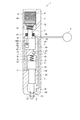
図2に示すように、ピエゾ駆動体91の充電が開始されると、ピエゾ駆動体91は軸方向に伸長するとともに、その端部で加圧ピストン5のフランジ部52をスプリング53の付勢力に抗して噴孔22方向へ押圧する。これにより、圧力制御部7においては、ピストン50がロッド部51を介して加圧室73の容積が減少する方向へ押圧される。その結果、加圧室73内部の燃料が加圧される。加圧室73内部の燃料が加圧されると、圧力室連通路75を経由して当該加圧室73に連通する圧力制御室71内部の燃料の圧力が上昇する。圧力制御室71の圧力は、当該圧力制御室71を形成するニードル3、およびノズルボディ2のニードル室105を構成する各壁面に作用する。そのため、圧力制御室71内部の燃料の圧力が上昇すると、ニードル3の大径部30が第1付勢部材33の付勢力に抗して軸方向反弁座23側へ押し上げられることにより、弁部32が弁座23から離座する。これにより、第1背圧室72内の燃料は、燃料通路100を経由して燃料溜り室102に流入する。そして、ニードル3の弁部32が弁座23から離座することにより燃料溜り室102と燃料室101とは連通し、噴孔21から燃料が噴射される。
As shown in FIG. 2, when charging of the
また、加圧室73内部の燃料が加圧された状態では、当該加圧室73に連通する連通路107およびダンパ通路108では、逆止弁77およびダンパピストン81より加圧室73側の、圧力室70に含まれる空間内における燃料の圧力も上昇している。この圧力室70の圧力は、当該圧力室70を形成する逆止弁77、ダンパピストン81、および連通路107とダンパ通路108を構成するノズルボディ2の各壁面に作用する。これにより、逆止弁77は第1背圧室72側へ付勢されて連通路107による加圧室73と第1背圧室72との連通が遮断され、ダンパピストン81は、ダンパ室82内の第1背圧室72側に設置されたダンパスプリング83による加圧室73方向の付勢力に抗して圧力室70内の高圧化された燃料に付勢され、当該ダンパ室82内において背圧室72側へ移動する。その結果、ニードル3の上昇に先立って、逆止弁77により連通を断たれた圧力室70と供給圧空間40とでは内部の燃料の圧力に圧力差が発生し、ピストン50に圧縮されたことによる圧力室70の容積の減少量は、ダンパ室82内のダンパピストン81よりも加圧室73側で当該ダンパピストン81の移動にて容積が増加した分だけ相殺されて小さくなる。このダンパ部8における作動では、圧力室70の容積の減少量をダンパピストン81の作動で補正して小さく抑えることにより、圧力室70の圧力の上昇量を抑えている。なお、ニードル3の上昇とともにその大径部30と圧力制御室71を形成するノズルボディ2の対向する壁面との距離が離れ、圧力室70の容積が増加しその内部の燃料の圧力が低下するのに伴い、圧力室70内の燃料の付勢力に抗してダンパスプリング83がダンパピストン81を加圧室73側へ付勢するようになり、当該ダンパピストン81はニードル3が上昇して弁部32が弁座23から離座する際には初期位置に復帰することとなる。
In the state where the fuel in the pressurizing
その後、ピエゾ駆動体91の放電が開始されると、ピエゾスタック91は軸方向に収縮する。これにより、加圧ピストン5のフランジ部52を押圧していたピエゾスタック91の端部は、反ピストン50方向へ移動する。このとき、加圧ピストン5は、スプリング53の付勢力により駆動部9方向、すなわち加圧室73の容積が増大する方向に移動する。その結果、加圧室73内部の燃料の圧力が低下するとともに、連通路107を経由して第1背圧室72から加圧室73に燃料が流入する。加圧室73内部の燃料の圧力が低下すると、圧力室連通路75を経由して当該加圧室73に連通する圧力制御室71内部の燃料の圧力も低下する。このとき、ニードル3は、スプリング33の付勢力によって弁座23方向へ移動し、弁部32が弁座23に着座する。これにより、燃料溜り室102と燃料室101との間は遮断され、噴孔21からの燃料の噴射は終了する。
Thereafter, when the discharge of the
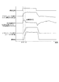
以上詳述した燃料噴射装置1の作動における主な構成の挙動は、図3に示すタイムチャートに顕れる如くである。なお、図3において、実線のグラフは、本発明の第1実施形態による燃料噴射装置1の作動を示すものである。また、点線のグラフは、燃料噴射装置1からダンパ通路108およびダンパ部8を除く構成による、従来の加圧開弁型燃料噴射装置の作動を比較例として示すものである。
The behavior of the main components in the operation of the
図3によれば、まず、燃料噴射装置1による燃料噴射のタイミングおよび噴射量を制御するアクチュエータとしての機能を担う駆動部9に噴射信号が入力された時点t0で、上述したようなピエゾ駆動体91への通電がなされる。そして、ピエゾ駆動体91に駆動される加圧ピストン5にて圧力室70が加圧され、時点t1で圧力制御室71内の圧力がニードル3を押し上げるのに最低限必要な圧力である「必要開弁圧」に到達することにより、ニードル3が変位して噴孔21が開放され、通常、噴射信号が入力されているうちは燃料噴射が行われる。その後、アクチュエータとしての駆動部9への噴射信号の入力が停止されることによってピエゾ駆動体91の放電が開始され、圧力室70の圧力が流入口22から供給される燃料の圧力よりも一時的に下がるとともにニードル3が変位し、噴孔21が塞がれることで燃料噴射が終了する。燃料噴射の終了後、圧力室70の内部には燃料通路100に蓄圧室4からの燃料が供給された燃料が流入するため、一旦低下した圧力室70の圧力も噴孔21開放前の圧力にまで復帰する。
According to FIG. 3, first, at the time t0 when an injection signal is input to the
このような一連の作動中、ニードル3が上昇している時点t2において、従来の燃料噴射装置では、圧力室70と供給圧空間40との圧力差である「圧力制御室圧」は、上述した「必要開弁圧」よりも低下しており、このため当該時点t2でのノズルボディ2に対するニードル3の変位の速度が低下するとともに、燃料噴射量が増加する速度も小さくなってしまう。その結果、単位時間あたりの燃料噴射量が所望の量に到達するのに時間がかかり、駆動部9に入力された噴射信号通りに燃料噴射量を制御するのが困難になり、良好な作動応答が得られないこととなる。このようにダンパ部8が設けられていない従来の燃料噴射装置で作動応答が遅れる理由は、ニードル3の大径部30の変位に伴う、圧力室70における時点t1から時点t2での容積変化量が大きいことに起因する、当該圧力室70の大きな圧力変化である。そこで、本発明の第1実施形態による燃料噴射装置1では、ダンパ部8を設置したことにより、圧力室70の圧力変化に伴いダンパピストン81にて当該圧力室70の容積を一旦増加させ、ニードル3の上昇による圧力室70の容積増加に伴いダンパピストン81にて当該圧力室70の容積を再び減少させることで、時点t1から時点t2までの容積変化の幅を小さく抑えている。その結果、図3の実線のグラフに顕れているとおり、「圧力制御室圧」の圧力変化の幅は小さく抑えられ、当該「圧力制御室圧」は時点t1から時点t2までの間、「必要開弁圧」より大きな圧力に保持される。
In such a series of operations, at the time point t2 when the
したがって、本実施形態によれば、圧力室70の圧力変化を緩和してニードル3の上昇速度の低下を抑制し、単位時間あたりの燃料噴射量をよりすばやく所望の量まで増加させることができるため、噴射信号の入力に即して燃料噴射量を制御することができる。そして、安定した作動応答で燃料噴射の制御をすることが可能となり、特に、開弁時における燃料噴射初期での噴霧悪化を回避し、内燃機関のエミッションを低減し、燃料の燃焼効率を向上させて燃費を改善することができる。
Therefore, according to the present embodiment, the pressure change in the
(第2実施形態)
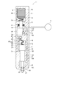
続いて、本発明の第2実施形態による燃料噴射装置を図4に示す。なお、第1実施形態と実質的に同一の構成部位には同一の符号を付し、説明を省略する。
第2実施形態によると、第1実施形態の連通路107およびダンパ通路108に相当する、圧力室70と供給圧空間40とを連通する連通路507およびダンパ通路508が、加圧ピストン5の内部に設けられている。つまり、連通路507とダンパ通路508とは、加圧室73と第2背圧室74とを連通するようにピストン50の内壁に形成されており、連通路507には加圧室73内部で加圧された燃料が第2背圧室74に漏出するのを防ぐよう逆止弁77が設けられ、ダンパ通路508に設けられたダンパ部8は、ピストン50の内壁に形成されたピストン室84に、ダンパピストン81、およびダンパピストン81を第2配圧室74側から加圧室73側へ付勢するダンパスプリング83が収容されて構成されている。このように、逆止弁77およびダンパ8ならびにそれぞれの構成を設ける通路は、供給圧空間40と圧力室70とを連通する通路として、ノズルボディ2以外に形成してもよい。
(Second Embodiment)
Next, a fuel injection device according to a second embodiment of the present invention is shown in FIG. In addition, the same code | symbol is attached | subjected to the component substantially the same as 1st Embodiment, and description is abbreviate | omitted.
According to the second embodiment, the
(第3実施形態、第4実施形態)
第2実施形態の変形例として、図5および図6に示す第3実施形態および第4実施形態の構成が挙げられる。第1実施形態または第2実施形態と実質的に同一の構成部位には同一の符号を付し、説明を省略する。
図5に示す本発明の第3実施形態による燃料噴射装置では、ダンパ通路508をピストン50に、連通路107をノズルボディ2に形成している。そして、ダンパ通路508には第2実施形態と実質的に同一の構成によるダンパ部8が設けられ、連通路107には第1実施形態と同様に逆止弁77が設けられている。
また、図6に示す本発明の第4実施形態による燃料噴射装置では、ダンパ通路108をノズルボディ2に、連通路507をピストン50に形成している。そして、ダンパ通路108には第1実施形態と実質的に同一の構成によるダンパ部8が設けられ、連通路507には第2実施形態と同様に逆止弁77が設けられている。
(3rd Embodiment, 4th Embodiment)
As a modification of the second embodiment, the configurations of the third embodiment and the fourth embodiment shown in FIGS. 5 and 6 may be mentioned. Components that are substantially the same as those in the first embodiment or the second embodiment are denoted by the same reference numerals, and description thereof is omitted.
In the fuel injection device according to the third embodiment of the present invention shown in FIG. 5, the
In the fuel injection device according to the fourth embodiment of the present invention shown in FIG. 6, the
(その他の実施形態)
上記複数の実施形態にて例示したように、ダンパ部8および逆止弁77はいずれも、実質的に圧力室70と供給圧空間40とを連通する通路を設けて設置するのであれば、どこに設けるかは任意である。その他、ニードル3に圧力室70と供給圧空間40とを連通する通路を設けることにより、ダンパ部8または逆止弁77、もしくはその両方を設ける構成としてもよい。
なお、本発明のその他の実施形態では、ダンパの構成は圧力室と燃料通路に連通する空間とを接続する通路に設けられるピストンに限定されるものではなく、圧力室の圧力変化を緩和可能なものであればいかなる構成のダンパを設けてもよい。特に、当該ダンパは、圧力室の容積を調整する構成であるのが望ましく、例えば、圧力室に接続する通路に連通する空間を形成し、その容積を拡大及び縮小させるように伸縮する構成等が例示される。
(Other embodiments)
As exemplified in the above embodiments, the
In other embodiments of the present invention, the configuration of the damper is not limited to the piston provided in the passage connecting the pressure chamber and the space communicating with the fuel passage, and the pressure change in the pressure chamber can be reduced. Any configuration of damper may be provided. In particular, the damper is preferably configured to adjust the volume of the pressure chamber. For example, the damper forms a space communicating with a passage connected to the pressure chamber, and expands and contracts to expand and contract the volume. Illustrated.
また、上述の複数の実施形態では、燃料噴射装置をコモンレール式のディーゼル内燃機関に適用した例について説明した。本発明のその他の実施形態では、他の形式のディーゼル内燃機関またはガソリン内燃機関に適用してもよい。
さらに、上述の複数の実施形態では、加圧手段として加圧ピストンを用い、当該加圧ピストンをピエゾ駆動体にて駆動する構成を例示して説明した。本発明のその他の実施形態では、ピエゾ駆動体に代えて、供給される電力に応じて変位量が変化するその他の電歪素子、磁歪素子あるいはリニアソレノイドなどを適用してもよい。もちろん、圧力室内部の燃料を加圧可能なものであれば、加圧ピストンに代わる他の加圧手段を適用して本発明を構成してもよい。
以上説明したように、本発明は上記実施形態に限定されるものではなく、その要旨を逸脱しない範囲で種々の実施形態に適用可能である。
In the above-described embodiments, the example in which the fuel injection device is applied to a common rail type diesel internal combustion engine has been described. Other embodiments of the invention may be applied to other types of diesel or gasoline internal combustion engines.
Furthermore, in the above-described plurality of embodiments, a configuration in which a pressurizing piston is used as the pressurizing unit and the pressurizing piston is driven by a piezo driver is described. In other embodiments of the present invention, other electrostrictive elements, magnetostrictive elements, linear solenoids, or the like whose displacement amount changes according to the supplied power may be applied instead of the piezo driver. Of course, as long as the fuel in the pressure chamber can be pressurized, other pressurizing means instead of the pressurizing piston may be applied to constitute the present invention.
As described above, the present invention is not limited to the above-described embodiment, and can be applied to various embodiments without departing from the gist thereof.
1:燃料噴射装置、2:ノズルボディ、3:ニードル、4:蓄圧室、5:加圧ピストン(加圧手段)、7:圧力制御部、8:ダンパ部(ダンパ)、9:駆動部、21:噴孔、22:流入口、23:弁座、30:大径部、31:小径部、32:弁部、33:第1付勢部材、40:供給圧空間、50:ピストン(加圧手段)、51:ロッド部、52:フランジ部、53:第2付勢部材、61:ゴムシール、70:圧力室、71:圧力制御室、72:第1背圧室、73:加圧室、74:第2背圧室、75:圧力室連通路、77:逆止弁、81:ダンパピストン(ダンパ)、82:ダンパ室(ダンパ)、83:ダンパスプリング(ダンパ)、90:駆動体収容室、91:ピエゾ駆動体、100:燃料通路、101:燃料室、102:燃料溜り室、103:ニードル室、104:摺動室、105:ピストン室、107:連通路、108:ダンパ通路 1: fuel injection device, 2: nozzle body, 3: needle, 4: pressure accumulating chamber, 5: pressurizing piston (pressurizing means), 7: pressure control unit, 8: damper unit (damper), 9: drive unit, 21: injection hole, 22: inflow port, 23: valve seat, 30: large diameter portion, 31: small diameter portion, 32: valve portion, 33: first biasing member, 40: supply pressure space, 50: piston Pressure means), 51: rod portion, 52: flange portion, 53: second urging member, 61: rubber seal, 70: pressure chamber, 71: pressure control chamber, 72: first back pressure chamber, 73: pressure chamber 74: second back pressure chamber, 75: pressure chamber communication passage, 77: check valve, 81: damper piston (damper), 82: damper chamber (damper), 83: damper spring (damper), 90: driving body Storage chamber, 91: Piezoelectric drive body, 100: Fuel passage, 101: Fuel chamber, 102: Fuel reservoir chamber, 10 Needle chamber, 104: sliding chamber, 105: piston chamber, 107: communication passage, 108: damper passage
Claims (9)
前記ノズルボディの内部を往復移動することによって前記噴孔を閉塞および開放するよう構成されたニードルと、
内部の燃料の圧力が高まると前記ニードルを前記噴孔の開放方向へ付勢する圧力室を有する圧力制御部と、
前記圧力室の圧力を上昇させることが可能な加圧手段と、を備える燃料噴射装置であって、
前記圧力制御部は、前記圧力室の圧力の上昇に伴い作動し、当該圧力室における圧力変化を緩和するダンパを含んでなることを特徴とする燃料噴射装置。 A nozzle body that forms a fuel passage through which fuel is supplied from the outside and forms a nozzle hole through which the fuel is injected to the outside downstream of the fuel passage;
A needle configured to close and open the nozzle hole by reciprocating inside the nozzle body;
A pressure control unit having a pressure chamber that urges the needle in the opening direction of the nozzle hole when the pressure of the internal fuel increases;
A fuel injection device comprising a pressurizing means capable of increasing the pressure of the pressure chamber,
The fuel injection device according to claim 1, wherein the pressure control unit includes a damper that operates as the pressure in the pressure chamber increases and relaxes a pressure change in the pressure chamber.
前記圧力制御部は、前記大径部を挟んで前記圧力室の反対側に形成され、前記燃料通路に連通し、内部の燃料の圧力が高まると、前記ニードルを前記噴孔の閉塞方向へ付勢する背圧室を有することを特徴とする請求項1から3のいずれか一項に記載の燃料噴射装置。 The needle has a large-diameter portion that slides on the inner wall of the nozzle body,
The pressure control unit is formed on the opposite side of the pressure chamber across the large-diameter portion, communicates with the fuel passage, and attaches the needle in the closing direction of the nozzle hole when the internal fuel pressure increases. The fuel injection device according to any one of claims 1 to 3, further comprising a back pressure chamber.
前記ノズルボディの内部を往復移動することによって前記噴孔を閉塞および開放するよう構成されたニードルと、
一端が前記ノズルボディの内壁に取り付けられ、他端が前記ニードルを前記噴孔の閉塞方向へ付勢する第1付勢部材と、
内部の燃料の圧力が高まると前記第1付勢部材の付勢力に抗して前記ニードルを前記噴孔の開放方向へ付勢する圧力室を有する圧力制御部と、
前記ノズルボディの内部を往復移動することによって前記圧力室の圧力を変化させる加圧ピストンと、
前記圧力室の圧力が低下する方向に前記加圧ピストンを付勢する第2付勢部材と、
前記ノズルボディに一端が固定され通電量に応じて伸長し、前記第2付勢部材の付勢力に抗して前記圧力室の圧力を上昇させる方向に前記加圧ピストンを押圧するピエゾ駆動体と、
を備える燃料噴射装置であって、
前記圧力制御部は、前記圧力室の圧力の上昇に伴い当該圧力室の容積を増加させるよう作動するダンパを含んでなることを特徴とする燃料噴射装置。 A nozzle body that forms a fuel passage through which fuel is supplied from the outside and forms a nozzle hole through which the fuel is injected to the outside downstream of the fuel passage;
A needle configured to close and open the nozzle hole by reciprocating inside the nozzle body;
A first urging member having one end attached to the inner wall of the nozzle body and the other end urging the needle in the closing direction of the nozzle hole;
A pressure control unit having a pressure chamber for urging the needle in the opening direction of the nozzle hole against the urging force of the first urging member when the pressure of the internal fuel increases;
A pressure piston that changes the pressure in the pressure chamber by reciprocating in the nozzle body; and
A second biasing member that biases the pressurizing piston in a direction in which the pressure of the pressure chamber decreases;
A piezoelectric drive body that is fixed at one end to the nozzle body and extends in accordance with an energization amount and presses the pressure piston in a direction to increase the pressure in the pressure chamber against the urging force of the second urging member; ,
A fuel injection device comprising:
The fuel injection device according to claim 1, wherein the pressure control unit includes a damper that operates to increase the volume of the pressure chamber as the pressure of the pressure chamber increases.
前記圧力制御部は、前記大径部を挟んで前記圧力室の反対側に形成され、前記燃料通路に連通し、内部の燃料の圧力が高まると、前記ニードルを前記噴孔の閉塞方向へ付勢する背圧室を有することを特徴とする請求項6または7に記載の燃料噴射装置。 The needle has a large-diameter portion that slides on the inner wall of the nozzle body,
The pressure control unit is formed on the opposite side of the pressure chamber across the large-diameter portion, communicates with the fuel passage, and attaches the needle in the closing direction of the nozzle hole when the internal fuel pressure increases. 8. The fuel injection device according to claim 6, further comprising a back pressure chamber.
Priority Applications (3)
| Application Number | Priority Date | Filing Date | Title |
|---|---|---|---|
| JP2008182372A JP4662292B2 (en) | 2008-07-14 | 2008-07-14 | Fuel injection device |
| DE102009027214.3A DE102009027214B4 (en) | 2008-07-14 | 2009-06-25 | Fuel injection device |
| US12/499,259 US8342424B2 (en) | 2008-07-14 | 2009-07-08 | Fuel injection apparatus |
Applications Claiming Priority (1)
| Application Number | Priority Date | Filing Date | Title |
|---|---|---|---|
| JP2008182372A JP4662292B2 (en) | 2008-07-14 | 2008-07-14 | Fuel injection device |
Publications (2)
| Publication Number | Publication Date |
|---|---|
| JP2010019213A true JP2010019213A (en) | 2010-01-28 |
| JP4662292B2 JP4662292B2 (en) | 2011-03-30 |
Family
ID=41427444
Family Applications (1)
| Application Number | Title | Priority Date | Filing Date |
|---|---|---|---|
| JP2008182372A Active JP4662292B2 (en) | 2008-07-14 | 2008-07-14 | Fuel injection device |
Country Status (3)
| Country | Link |
|---|---|
| US (1) | US8342424B2 (en) |
| JP (1) | JP4662292B2 (en) |
| DE (1) | DE102009027214B4 (en) |
Cited By (1)
| Publication number | Priority date | Publication date | Assignee | Title |
|---|---|---|---|---|
| JP2017008941A (en) * | 2015-06-24 | 2017-01-12 | グレート プレインズ ディーゼル テクノロジーズ,エル.シー. | Magnetostrictive actuator and modulation of fuel injection rate by hydrodynamic coupler |
Families Citing this family (6)
| Publication number | Priority date | Publication date | Assignee | Title |
|---|---|---|---|---|
| EP2806149A1 (en) * | 2013-05-23 | 2014-11-26 | Delphi International Operations Luxembourg S.à r.l. | Fuel injector |
| US20150101323A1 (en) * | 2013-10-15 | 2015-04-16 | Edwin Newman | Using gravity and piezoelectric elements to produce electric power |
| WO2015126182A1 (en) * | 2014-02-21 | 2015-08-27 | 삼성전자 주식회사 | Method for displaying content and electronic device therefor |
| DE102014211334B3 (en) * | 2014-06-13 | 2015-08-27 | Continental Automotive Gmbh | Method for characterizing a hydraulic coupling element of a piezo injector |
| DE102014219199A1 (en) * | 2014-09-23 | 2016-03-24 | Robert Bosch Gmbh | fuel injector |
| CN112221736B (en) * | 2020-09-14 | 2021-06-29 | 安徽工程大学 | Pressure-adjustable pressure-stabilizing nozzle |
Citations (2)
| Publication number | Priority date | Publication date | Assignee | Title |
|---|---|---|---|---|
| JPH1150930A (en) * | 1997-07-30 | 1999-02-23 | Toyota Motor Corp | Accumulator fuel injection system |
| JP2006214317A (en) * | 2005-02-02 | 2006-08-17 | Toyota Motor Corp | Fuel injection valve |
Family Cites Families (5)
| Publication number | Priority date | Publication date | Assignee | Title |
|---|---|---|---|---|
| US5287838A (en) * | 1993-02-26 | 1994-02-22 | Caterpillar Inc. | Compact reverse flow check valve assembly for a unit fluid pump-injector |
| DE19952512A1 (en) * | 1999-10-30 | 2001-05-10 | Bosch Gmbh Robert | Pressure booster and fuel injection system with a pressure booster |
| JP4019934B2 (en) * | 2002-12-26 | 2007-12-12 | 株式会社デンソー | Control valve and fuel injection valve |
| DE10329732A1 (en) | 2003-07-02 | 2005-02-03 | Robert Bosch Gmbh | Fuel injection system for internal combustion engines |
| JP4380549B2 (en) * | 2005-01-31 | 2009-12-09 | 株式会社デンソー | Fuel injection valve |
-
2008
- 2008-07-14 JP JP2008182372A patent/JP4662292B2/en active Active
-
2009
- 2009-06-25 DE DE102009027214.3A patent/DE102009027214B4/en not_active Expired - Fee Related
- 2009-07-08 US US12/499,259 patent/US8342424B2/en active Active
Patent Citations (2)
| Publication number | Priority date | Publication date | Assignee | Title |
|---|---|---|---|---|
| JPH1150930A (en) * | 1997-07-30 | 1999-02-23 | Toyota Motor Corp | Accumulator fuel injection system |
| JP2006214317A (en) * | 2005-02-02 | 2006-08-17 | Toyota Motor Corp | Fuel injection valve |
Cited By (1)
| Publication number | Priority date | Publication date | Assignee | Title |
|---|---|---|---|---|
| JP2017008941A (en) * | 2015-06-24 | 2017-01-12 | グレート プレインズ ディーゼル テクノロジーズ,エル.シー. | Magnetostrictive actuator and modulation of fuel injection rate by hydrodynamic coupler |
Also Published As
| Publication number | Publication date |
|---|---|
| DE102009027214B4 (en) | 2018-09-20 |
| US8342424B2 (en) | 2013-01-01 |
| JP4662292B2 (en) | 2011-03-30 |
| US20100006676A1 (en) | 2010-01-14 |
| DE102009027214A1 (en) | 2010-01-21 |
Similar Documents
| Publication | Publication Date | Title |
|---|---|---|
| US6651630B2 (en) | High pressure fuel pump | |
| JP4662292B2 (en) | Fuel injection device | |
| WO2007139620A1 (en) | Fuel injector control system | |
| JP4297879B2 (en) | Injector | |
| JP4609271B2 (en) | Fuel injection valve | |
| JP4023804B2 (en) | Injector for internal combustion engine | |
| JP2010084761A (en) | Fuel injection system equipped with high pressure pump having magnetically operable suction valve | |
| JP5146837B2 (en) | Fuel injection device | |
| KR102452468B1 (en) | Pumping injector for engine | |
| JP6281296B2 (en) | Fuel injection valve | |
| WO2013147078A1 (en) | Hydraulic-drive fuel injection device and internal combustion engine | |
| JP2010236375A (en) | Fuel injection valve | |
| JP2005076510A (en) | Fuel injection device and its control device | |
| JP4308449B2 (en) | Fuel injection valve | |
| JP5942797B2 (en) | Fuel injection valve | |
| JP2016050562A (en) | Fuel injection valve | |
| JP6508146B2 (en) | Fuel injection device | |
| JP2005207323A (en) | Fuel injection device | |
| JP2007138852A (en) | Variable injection hole injector | |
| JP6508147B2 (en) | Fuel injection device | |
| JP6458747B2 (en) | Fuel injection device | |
| JP6547660B2 (en) | Fuel injection valve | |
| JP6233109B2 (en) | Fuel injection valve | |
| JP6149766B2 (en) | Fuel injection valve | |
| JP2015090088A (en) | Fuel injection valve |
Legal Events
| Date | Code | Title | Description |
|---|---|---|---|
| A621 | Written request for application examination |
Free format text: JAPANESE INTERMEDIATE CODE: A621 Effective date: 20100302 |
|
| A131 | Notification of reasons for refusal |
Free format text: JAPANESE INTERMEDIATE CODE: A131 Effective date: 20100621 |
|
| A977 | Report on retrieval |
Free format text: JAPANESE INTERMEDIATE CODE: A971007 Effective date: 20100624 |
|
| A521 | Request for written amendment filed |
Free format text: JAPANESE INTERMEDIATE CODE: A523 Effective date: 20100726 |
|
| A131 | Notification of reasons for refusal |
Free format text: JAPANESE INTERMEDIATE CODE: A131 Effective date: 20100819 |
|
| A521 | Request for written amendment filed |
Free format text: JAPANESE INTERMEDIATE CODE: A523 Effective date: 20101008 |
|
| TRDD | Decision of grant or rejection written | ||
| A01 | Written decision to grant a patent or to grant a registration (utility model) |
Free format text: JAPANESE INTERMEDIATE CODE: A01 Effective date: 20101222 |
|
| A01 | Written decision to grant a patent or to grant a registration (utility model) |
Free format text: JAPANESE INTERMEDIATE CODE: A01 |
|
| A61 | First payment of annual fees (during grant procedure) |
Free format text: JAPANESE INTERMEDIATE CODE: A61 Effective date: 20101224 |
|
| R150 | Certificate of patent or registration of utility model |
Ref document number: 4662292 Country of ref document: JP Free format text: JAPANESE INTERMEDIATE CODE: R150 Free format text: JAPANESE INTERMEDIATE CODE: R150 |
|
| FPAY | Renewal fee payment (event date is renewal date of database) |
Free format text: PAYMENT UNTIL: 20140114 Year of fee payment: 3 |
|
| R250 | Receipt of annual fees |
Free format text: JAPANESE INTERMEDIATE CODE: R250 |
|
| R250 | Receipt of annual fees |
Free format text: JAPANESE INTERMEDIATE CODE: R250 |
|
| R250 | Receipt of annual fees |
Free format text: JAPANESE INTERMEDIATE CODE: R250 |
|
| R250 | Receipt of annual fees |
Free format text: JAPANESE INTERMEDIATE CODE: R250 |
|
| R250 | Receipt of annual fees |
Free format text: JAPANESE INTERMEDIATE CODE: R250 |
|
| R250 | Receipt of annual fees |
Free format text: JAPANESE INTERMEDIATE CODE: R250 |
|
| R250 | Receipt of annual fees |
Free format text: JAPANESE INTERMEDIATE CODE: R250 |
|
| R250 | Receipt of annual fees |
Free format text: JAPANESE INTERMEDIATE CODE: R250 |
|
| R250 | Receipt of annual fees |
Free format text: JAPANESE INTERMEDIATE CODE: R250 |
|
| R250 | Receipt of annual fees |
Free format text: JAPANESE INTERMEDIATE CODE: R250 |