JP2010018152A - Power seat for vehicles - Google Patents
Power seat for vehicles Download PDFInfo
- Publication number
- JP2010018152A JP2010018152A JP2008180202A JP2008180202A JP2010018152A JP 2010018152 A JP2010018152 A JP 2010018152A JP 2008180202 A JP2008180202 A JP 2008180202A JP 2008180202 A JP2008180202 A JP 2008180202A JP 2010018152 A JP2010018152 A JP 2010018152A
- Authority
- JP
- Japan
- Prior art keywords
- posture
- current
- electric motor
- time
- inrush
- Prior art date
- Legal status (The legal status is an assumption and is not a legal conclusion. Google has not performed a legal analysis and makes no representation as to the accuracy of the status listed.)
- Granted
Links
Images


Landscapes
- Seats For Vehicles (AREA)
- Control Of Multiple Motors (AREA)
Abstract
Description
本発明は、乗員の姿勢を保持するとともに、その姿勢を変更するための複数の姿勢調整部を有し、かつ、それら複数の姿勢調整部各々を駆動するための複数の電動モータを備える車両用電動シートに関するものである。 The present invention is for a vehicle having a plurality of posture adjustment units for maintaining the posture of an occupant and changing the posture, and including a plurality of electric motors for driving each of the plurality of posture adjustment units. The present invention relates to an electric seat.
なお、姿勢調整部としては、例えば、シート全体を前後方向させるためのスライド調整部、シートバックの傾斜角度を変更するためのリクライニング調整部、シート全体を上下動させるためのリフター調整部、及び座部前方側のみを上下動させるためのバーチカル調整部等がある。 The posture adjustment unit includes, for example, a slide adjustment unit for moving the entire seat back and forth, a reclining adjustment unit for changing the inclination angle of the seat back, a lifter adjustment unit for moving the entire seat up and down, and a seat. There is a vertical adjustment unit for moving only the front side of the unit up and down.
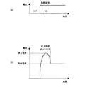
通常、電動モータに電圧を印加して電動モータを起動(始動)させると、図12(a)及び図12(b)に示すように、電圧を印加した直後においては、電動モータが定常状態となって電流が安定したときの電流(以下、この電流を作動電流という。)より大きな電流(以下、この電流を突入電流又は始動電流という。)が流れる。因みに、突入電流値は、電動モータや負荷状態によっても異なるが、概ね作動電流の5〜7倍程度の大きさとなる。 Normally, when a voltage is applied to the electric motor to start (start) the electric motor, as shown in FIGS. 12 (a) and 12 (b), the electric motor is in a steady state immediately after the voltage is applied. Thus, a larger current (hereinafter, this current is referred to as an inrush current or a starting current) flows than the current when the current is stabilized (hereinafter, this current is referred to as an operating current). Incidentally, the inrush current value varies depending on the electric motor and the load state, but is approximately 5 to 7 times the operating current.
このため、複数の電動モータの作動を制御する際に、複数の電動モータを同時に起動すると、複数の電動モータに電力を供給する電源部に、非常に大きな電流を必要とし、電源事情によっては必要な電流容量が確保できず、作動できない可能性がある。 For this reason, when controlling the operation of a plurality of electric motors, if a plurality of electric motors are activated at the same time, a very large current is required for the power supply unit that supplies power to the plurality of electric motors, and may be necessary depending on the power supply circumstances. A large current capacity cannot be secured and there is a possibility that it cannot be operated.
そこで、特許文献1に記載の発明では、各電動モータの起動タイミングをずらして順次起動することにより、突入電流が発生する時間(以下、この時間を突入時間という。)が重ならないようにしている。
ところで、特許文献1に記載の発明を、上記の車両用電動シートに適用すると、全ての姿勢調整部の設定が完了するまでに要する時間(以下、この時間を作動完了時間という。)が長くなってしまうおそれが高い。 By the way, when the invention described in Patent Document 1 is applied to the above-described electric vehicle seat, the time required to complete the setting of all the posture adjustment units (hereinafter, this time is referred to as the operation completion time) becomes longer. There is a high risk that
すなわち、各電動モータを作動させて各調整部を各々の目標位置に設定する場合、各電動モータの作動時間は、当然ながら目標位置によって異なる。
このため、例えば、最後に起動される電動モータ(以下、この電動モータを最終起動モータという。)の作動時間を長くせざるを得ない場合には、最終起動モータの作動時間が長いにも拘わらず、最終起動モータ以外の他の電動モータの突入時間が経過した後、又は他の電動モータが停止した後でなければ、最終起動モータを起動させることができないので、作動完了時間が長くなってしまうおそれが高い。
That is, when each electric motor is operated and each adjustment unit is set to each target position, the operation time of each electric motor naturally varies depending on the target position.
For this reason, for example, when the operating time of the last-started electric motor (hereinafter, this electric motor is referred to as a final starting motor) must be extended, the operating time of the final starting motor is long. Since the final starter motor can only be started after the rush time of another electric motor other than the final starter motor has elapsed or after the other electric motor has stopped, the operation completion time becomes longer. There is a high risk of it.
これに対しては、電源部の容量を十分に大きくして、複数の電動モータを全て同時に起動可能とすれば解決することができるものの、この解決手法では、電源部の大型化及び製造原価上昇を招いてしまう。 This can be solved by sufficiently increasing the capacity of the power supply unit so that a plurality of electric motors can be started all at the same time. Will be invited.
本発明は、上記点に鑑み、電源部の大型化及び製造原価上昇を抑制しつつ、作動完了時間の短縮を図ることを目的とする。 In view of the above points, an object of the present invention is to shorten an operation completion time while suppressing an increase in the size of a power supply unit and an increase in manufacturing cost.
本発明は、上記目的を達成するために、請求項1に記載の発明では、車両を運転操作する乗員の姿勢を保持するとともに、その姿勢を変更するための複数の姿勢調整部(1、3、5、7)を有し、かつ、複数の姿勢調整部(1、3、5、7)各々を駆動するための複数の電動モータ(1A、3A、5A、7A)を備える車両用電動シートであって、複数の電動モータ(1A、3A、5A、7A)に電力を供給する電源部(11)と、電動モータ(1A、3A、5A、7A)各々の突入電流、突入時間、作動電流及び作動速度が記憶される記憶部(13)と、複数の姿勢調整部(1、3、5、7)各々の現在の状態を検出する状態検出手段(1C、3C、5C、7C)と、目標とする姿勢を読み込む読込手段(S5)と、記憶部(13)に記憶されている突入電流、突入時間、作動電流及び作動速度、読込手段(S5)により読み込まれた目標姿勢状態、並びに状態検出手段(1C、3C、5C、7C)により検出された現在の状態に基づいて、突入時間も含めた現在の状態を目標姿勢状態とするために必要な作動時間を、電動モータ(1A、3A、5A、7A)毎に求める作動時間算出手段(S7)と、複数の電動モータ(1A、3A、5A、7A)の作動を制御するとともに、作動時間算出手段(S7)により求められた作動時間のうち最大作動時間となった電動モータ(1A、3A、5A、7A)を最初に作動させる制御部(9)とを備えることを特徴とする。 In order to achieve the above object, according to the present invention, a plurality of posture adjusting units (1, 3, 3) for maintaining the posture of an occupant who operates a vehicle and changing the posture are provided. 5, 7) and a plurality of electric motors (1A, 3A, 5A, 7A) for driving each of the plurality of posture adjusting sections (1, 3, 5, 7). The power supply unit (11) for supplying power to the plurality of electric motors (1A, 3A, 5A, 7A) and the inrush current, the inrush time, and the operating current of each of the electric motors (1A, 3A, 5A, 7A) And a storage unit (13) in which the operation speed is stored, and state detection means (1C, 3C, 5C, 7C) for detecting a current state of each of the plurality of posture adjustment units (1, 3, 5, 7), Reading means (S5) for reading the target posture, and storage in the storage unit (13) Rush current, rush time, operating current and operating speed, the target posture state read by the reading means (S5), and the current state detected by the state detecting means (1C, 3C, 5C, 7C). Then, an operation time calculation means (S7) for obtaining an operation time required for setting the current state including the entry time to the target posture state for each electric motor (1A, 3A, 5A, 7A), and a plurality of electric motors While controlling the operation of the motor (1A, 3A, 5A, 7A), the electric motor (1A, 3A, 5A, 7A) having the maximum operation time out of the operation time obtained by the operation time calculation means (S7). And a control unit (9) to be operated first.
これにより、請求項1に記載の発明では、最大作動時間となった電動モータ(以下、この電動モータを最大作動時間モータという。)を最初に起動するので、電源部(11)の電流容量を超えない範囲で、最大作動時間モータ以外の他の電動モータを最大作動時間モータと同時に作動させた場合、複数の電動モータ(1A、3A、5A、7A)を同時に作動させる時間を長くすることが可能となり、作動完了時間の短縮を図ることが可能となる。 Thus, in the first aspect of the invention, since the electric motor having the maximum operating time (hereinafter, this electric motor is referred to as the maximum operating time motor) is first started, the current capacity of the power supply unit (11) is reduced. When other electric motors other than the maximum operating time motor are operated simultaneously with the maximum operating time motor within a range not exceeding, it is possible to lengthen the time for operating a plurality of electric motors (1A, 3A, 5A, 7A) simultaneously. This makes it possible to shorten the operation completion time.
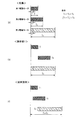
具体的には、例えば、3機の電動モータが設けられ、第1電動モータの作動時間をT1、第2電動モータの作動時間をT2、第3電動モータの作動時間をT3とし、各電動モータの突入時間t及び作動電流iは全て同じであって、かつ、T1<T2<T3、(T1+T2)<T3、電源部の電流容量を2機分(=2i)とした場合(図13(a)参照)、請求項1に記載の発明では、作動完了時間をT3とすることが可能となるのに対して、特許文献1に記載の発明において、第1電動モータ、第2電動モータ、第3電動モータの順で電動モータが起動すると、作動完了時間はT1+T3となる。 Specifically, for example, three electric motors are provided, the operation time of the first electric motor is T1, the operation time of the second electric motor is T2, and the operation time of the third electric motor is T3. The inrush time t and the operating current i are all the same, and T1 <T2 <T3, (T1 + T2) <T3, and the current capacity of the power supply unit is equivalent to two units (= 2i) (FIG. 13 (a In the invention described in claim 1, the operation completion time can be set to T3, whereas in the invention described in Patent Document 1, the first electric motor, the second electric motor, When the electric motor is started in the order of three electric motors, the operation completion time is T1 + T3.
すなわち、請求項1に記載の発明では、図13(b)に示すように、第3電動モータと第1電動モータとを同時に作動させた後、第1電動モータの停止後、第3電動モータと第2電動モータとを同時に作動させることができるので、作動完了時間はT3となる。 That is, in the first aspect of the present invention, as shown in FIG. 13B, after the third electric motor and the first electric motor are simultaneously operated, the third electric motor is stopped after the first electric motor is stopped. And the second electric motor can be operated simultaneously, so that the operation completion time is T3.
一方、特許文献1に記載の発明では、図13(c)に示すように、第1電動モータの起動後、突入時間が経過した後に第2電動モータが起動され、第1電動モータが停止した後に第3電動モータが起動されるので、作動完了時間はT1+T3となる。 On the other hand, in the invention described in Patent Document 1, as shown in FIG. 13C, after the first electric motor is started, the second electric motor is started after the rush time has elapsed, and the first electric motor is stopped. Since the third electric motor is activated later, the operation completion time is T1 + T3.
このように、請求項1に記載の発明では、電源部(11)の大型化及び製造原価上昇を抑制しつつ、作動完了時間を特許文献1に記載の発明より短縮することが可能となる。
なお、「最大作動時間モータを最初に起動する」とは、最大作動時間モータより先に起動させる電動モータが無いという意味である。したがって、例えば、最大作動時間モータである第3電動モータを起動した後に第2電動モータを起動させる場合は勿論、第3電動モータと第2電動モータとを同時に起動する場合も含まれる。
Thus, in the invention described in claim 1, it is possible to shorten the operation completion time compared to the invention described in Patent Document 1 while suppressing an increase in the size of the power supply unit (11) and an increase in manufacturing cost.
Note that “starting the maximum operating time motor first” means that there is no electric motor to start before the maximum operating time motor. Therefore, for example, the case where the second electric motor is started after starting the third electric motor, which is the maximum operating time motor, is included as well as the case where the third electric motor and the second electric motor are started simultaneously.
ところで、電動モータ(1A、3A、5A、7A)や姿勢調整部(1、3、5、7)の経年変化により、突入電流、突入時間、作動電流及び作動速度が変化するおそれがあるが、これらの値が変化すると、最大作動時間モータを正確に特定することができなくなるので、作動完了時間の短縮を図ることができなくなるおそれがある。 By the way, the rush current, the rush time, the working current, and the working speed may change due to the secular change of the electric motor (1A, 3A, 5A, 7A) and the posture adjusting unit (1, 3, 5, 7). If these values change, the maximum operation time motor cannot be accurately specified, and therefore it may not be possible to shorten the operation completion time.
これに対して、請求項2に記載の発明では、電動モータ(1A、3A、5A、7A)毎に、突入電流、突入時間、作動電流及び作動速度を検出する突入電流等検出手段(S19)と、突入電流等検出手段(S19)の検出結果を記憶部(13)に記憶させる書込手段(S27)とを備えているので、突入電流等が経年変化により変化しても、最大作動時間モータを正確に特定することができる。 On the other hand, in the invention described in claim 2, for each electric motor (1A, 3A, 5A, 7A), an inrush current detection means for detecting an inrush current, an inrush time, an operating current and an operating speed (S19). And a writing means (S27) for storing the detection result of the inrush current detection means (S19) in the storage section (13), the maximum operating time even if the inrush current changes due to secular change. The motor can be accurately identified.
したがって、請求項2に記載の発明では、経年変化の影響を受けることなく、安定的に作動完了時間を短縮することができる。
また、突入電流等は、電動モータ(1A、3A、5A、7A)の負荷、つまり、乗員が着座しているか否によって変化するおそれが高い。
Therefore, in the invention described in claim 2, the operation completion time can be stably shortened without being affected by the secular change.
Further, the inrush current or the like is likely to change depending on the load of the electric motor (1A, 3A, 5A, 7A), that is, whether or not an occupant is seated.
これに対して、請求項3に記載の発明では、電動モータ(1A、3A、5A、7A)毎に、突入電流、突入時間、作動電流及び作動速度を検出する突入電流等検出手段(S59)と、乗員が着座しているか否かを検出する着座検出手段(S67)と、乗員が着座している場合の突入電流等検出手段(S59)の検出結果であるか、又は乗員が着座していない場合の突入電流等検出手段(S59)の検出結果であるかを識別可能として記憶部(13)に記憶させる書込手段とを備え、作動時間算出手段(S41)は、着座検出手段(S31)の検出結果に応じた突入電流、突入時間、作動電流及び作動速度を記憶部(13)から読み込んで作動時間を求めることを特徴としているので、乗員が着座しているか否の影響を受けることなく、安定的に作動完了時間を短縮することができる。
On the other hand, in the invention described in
なお、請求項4に記載の発明では、目標とする姿勢が記憶されたポジションメモリ(13、ROM)を備えており、読込手段(S5)は、ポジションメモリ(13、ROM)に記憶された姿勢を目標姿勢状態として読み込むことを特徴とするものであり、請求項5に記載の発明では、読込手段(S5)は、無線通信を介して乗員が携帯している記憶装置に記憶された姿勢を目標姿勢状態として読み込むことを特徴とするものである。
In addition, in invention of Claim 4, the position memory (13, ROM) in which the target attitude | position was memorize | stored is provided, and the reading means (S5) is the attitude | position memorize | stored in the position memory (13, ROM). Is read as the target posture state. In the invention according to
請求項6に記載の発明では、車両を運転操作する乗員の姿勢を保持するとともに、その姿勢を変更するための複数の姿勢調整部(1、3、5、7)を有し、かつ、複数の姿勢調整部(1、3、5、7)各々を駆動するための複数の電動モータ(1A、3A、5A、7A)を備える車両用電動シートであって、複数の電動モータ(1A、3A、5A、7A)に電力を供給する電源部(11)と、複数の姿勢調整部(1、3、5、7)各々の現在の状態を検出する状態検出手段(1C、3C、5C、7C)と、目標とする姿勢を読み込む読込手段(S5)と、複数の電動モータ(1A、3A、5A、7A)の作動を制御するとともに、複数の姿勢調整部(1、3、5、7)のうち最も調整幅が大きい姿勢調整部を駆動する電動モータ(1A、3A、5A、7A)を最初に作動させる制御部(9)とを備えることを特徴とする。
In the invention according to claim 6, the posture of the occupant operating the vehicle is maintained, and a plurality of posture adjusting units (1, 3, 5, 7) for changing the posture are provided. An electric seat for a vehicle including a plurality of electric motors (1A, 3A, 5A, 7A) for driving each of the posture adjustment units (1, 3, 5, 7) of the plurality of electric motors (1A, 3A) 5A, 7A) and a state detection means (1C, 3C, 5C, 7C) for detecting the current state of each of the plurality of posture adjustment units (1, 3, 5, 7). ), A reading means (S5) for reading a target posture, and a plurality of electric motors (1A, 3A, 5A, 7A), and a plurality of posture adjusting units (1, 3, 5, 7). Of the electric motor (1A, 3A) that drives the posture adjustment unit with the
これにより、請求項6に記載の発明では、最大作動時間を算出するための制御を廃止して、制御を簡素なロジックとしながら、電源部(11)の大型化及び製造原価上昇を抑制しつつ、作動完了時間を特許文献1に記載の発明より短縮することが可能となる。 Accordingly, in the invention described in claim 6, the control for calculating the maximum operating time is abolished, and the control is made simple logic, while the increase in the size of the power supply unit (11) and the increase in the manufacturing cost are suppressed. The operation completion time can be shortened compared to the invention described in Patent Document 1.
因みに、上記各手段等の括弧内の符号は、後述する実施形態に記載の具体的手段等との対応関係を示す一例であり、本発明は上記各手段等の括弧内の符号に示された具体的手段に限定されるものではない。 Incidentally, the reference numerals in parentheses for each of the above means are examples showing the correspondence with the specific means described in the embodiments described later, and the present invention is indicated by the reference numerals in the parentheses of the above respective means. It is not limited to specific means.
本実施形態は、車両を運転操作する運転者が着座する運転者用のシートに、本発明に係る電動シートを適用したものであり、以下に本発明の実施形態を図面と共に説明する。
(第1実施形態)
1.図面の説明
図1は本実施形態に係る車両用電動シート(以下、シートと略す。)の概要を示すブロック図であり、図2は本実施形態に係る調整部制御を示すフローチャートであり、図3(a)〜図3(d)は駆動制御パターン例を示す図であり、図4は取得制御を示すフローチャートであり、図5は従来の技術に係る駆動制御パターンを示す図である。
In the present embodiment, an electric seat according to the present invention is applied to a driver's seat on which a driver who operates a vehicle is seated, and the embodiment of the present invention will be described below with reference to the drawings.
(First embodiment)
1. DESCRIPTION OF THE DRAWINGS FIG. 1 is a block diagram showing an outline of an electric vehicle seat (hereinafter abbreviated as a seat) according to this embodiment, and FIG. 2 is a flowchart showing control of an adjustment unit according to this embodiment. 3A to FIG. 3D are diagrams showing examples of drive control patterns, FIG. 4 is a flowchart showing acquisition control, and FIG. 5 is a diagram showing drive control patterns according to the prior art.
2.本実施形態に係る電動シートの構成(図1参照)
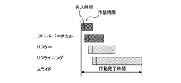
運転者用のシート(図示せず。)は、周知のごとく、運転者の運転姿勢を保持するための座部(図示せず)及びシートバック(背もたれ)等から構成されているとともに、その運転姿勢を変更するために複数の姿勢調整部1、3、5、7が設けられている。
2. Configuration of the electric seat according to the present embodiment (see FIG. 1)
As is well known, a driver's seat (not shown) is composed of a seat (not shown), a seat back (back), and the like for maintaining the driver's driving posture. In order to change the posture, a plurality of
なお、フロントバーチカル姿勢調整部1は、座部前方側のみを上下動させるためのものであり、リフター姿勢調整部3は、シート全体を上下動させるためのものであり、リクライニング姿勢調整部5は、シートのシートバックの傾斜角度(リクライニング)を変更するためのものであり、スライド位置調整部7は、シート全体を車両前後方向にスライド(平行移動)させるものである。
The front vertical posture adjustment unit 1 is for moving up and down only the seat front side, the lifter
そして、各姿勢調整部1、3、5、7は、電動モータ1A、3A、5A、7Aにより駆動され、かつ、これら電動モータ1A、3A、5A、7A(以下、これらの電動モータを総称するときは、電動モータ1A等という。)の駆動用電力は、駆動回路1B、3B、5B、7B(以下、これらの駆動回路を総称するときは、駆動回路1B等という。)を介して電源部11から供給されている。
And each attitude |
また、駆動回路1B等の制御、つまり電動モータ1A等の作動は電子制御装置(ECU)9により制御されており、この電子制御装置9は、CPU、RAM及びROM等からなる周知のマイクロコンピュータにて構成されている。因みに、駆動回路1B等を制御するためのプログラムは、ROMに予め記憶されている。
The control of the
また、記憶部13は、各電動モータ1A、3A、5A、7Aの突入電流、突入時間、作動電流及び作動速度等が記憶されるメモリであり、この記憶部13はフラッシュメモリ等の電力供給が停止したときであっても記憶内容を保持することができる不揮発性記憶装置にて構成されている。
The
ここで、作動電流とは、「背景技術」の欄で説明したように、電動モータ1A等が定常状態となって電流が安定したときの電流をいい、突入電流とは、電動モータ1A等に電圧を印加した直後において流れる作動電流より大きな電流をいう。
Here, as described in the “Background Art” section, the operating current refers to a current when the
また、突入時間とは、突入電流が発生している時間をいい、作動速度とは、電動モータ1A等を作動電流にて駆動した場合における姿勢調整部1、3、5、7(以下、これらを総称するときは、姿勢調整部1等という。)の作動(移動)速度をいう。
The inrush time refers to the time during which an inrush current is generated, and the operating speed refers to the
なお、作動速度は、突入電流が流れている状態と定常状態とでは異なるが、その差は僅かであるので、本実施形態では、作動電流にて電動モータ1A等を駆動したときにおける姿勢調整部1等の作動速度を作動速度としている。
Although the operating speed differs between the state where the inrush current flows and the steady state, the difference is slight. In this embodiment, the attitude adjustment unit when the
また、手動操作部15は、運転者等の乗員からの指示操作を受け付けて電動モータ1A等(駆動姿勢調整部1、3、5、7)を作動させるためのスイッチ類であり、本実施形態では、この手動操作部15によっても目標運転姿勢を設定することができる。
The
ここで、目標運転姿勢とは、電動モータ1A等を用いて各姿勢調整部1、3、5、7を自動的に作動させる際に、各姿勢調整部1、3、5、7の作動目標値を決定するためシートの状態をいう。そして、本実施形態では、手動操作部15を介して運転者等により設定された目標運転姿勢は、電子制御装置9のROM又は記憶部13に記憶される。
Here, the target driving posture is an operation target of each
なお、ROM等には、目標運転姿勢を示す初期値が予め(メーカ出荷時点で)記憶されており、運転者等により目標運転姿勢が設定された場合には、目標運転姿勢が乗員により設定された姿勢に更新される。 Note that an initial value indicating the target driving posture is stored in advance in the ROM or the like (at the time of shipment from the manufacturer), and when the target driving posture is set by the driver or the like, the target driving posture is set by the occupant. Updated to the correct posture.
また、検出部1C、3C、5C、7Cは、各姿勢調整部1、3、5、7(各電動モータ1A等)の現在の状態を検出する状態検出手段であり、これら各検出部1C、3C、5C、7C(以下、これらを総称するときは、検出部1C等という。)にて検出された姿勢調整部1等の状態(位置)を示す信号は、電子制御装置9に入力される。
The
なお、検出部1Cは、フロントバーチカル姿勢調整部1の状態を検出する手段であり、検出部3Cは、リフター姿勢調整部3の状態を検出する手段であり、検出部5Cは、リクライニング姿勢調整部5の状態を検出する手段であり、検出部7Cは、スライド位置調整部7の状態を検出する手段である。
The
3.本実施形態に係るシートの特徴的な作動制御
3.1.姿勢調整部の制御
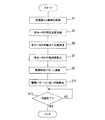
図2は姿勢調整部1等の制御作動(以下、この制御を調整部制御という。)を示すフローチャートであり、この調整部制御は、始動許可スイッチが投入された時に起動され、電子制御装置9(CPU)にて実行される。
3. Characteristic operation control of the seat according to the present embodiment 3.1. FIG. 2 is a flowchart showing a control operation of the attitude adjustment unit 1 and the like (hereinafter, this control is referred to as adjustment unit control). This adjustment unit control is activated when the start permission switch is turned on. This is executed by the electronic control unit 9 (CPU).
なお、始動許可スイッチとは、車載に搭載された電気機器に車載バッテリからの電力供給を可能とするためのスイッチであり、例えばイグニッションスイッチやアクセサリスイッチ等をいう。 The start permission switch is a switch for enabling electric power supplied from an in-vehicle battery to an electric device mounted on the vehicle, for example, an ignition switch or an accessory switch.
そして、調整部制御が起動されると、各電動モータ1A等についての突入電流、突入時間、作動電流及び作動速度(以下、これらの情報を突入電流等情報という。)が記憶部13から取得されるとともに(S1)、検出部1C等からの検出信号、つまり各電動モータ1A等の現在位置が取得される(S3)。
When the adjustment unit control is activated, the inrush current, the inrush time, the operating current, and the operating speed (hereinafter, these information are referred to as inrush current etc. information) for each
次に、目標運転姿勢、つまり電動モータ1A等の作動完了位置が電子制御装置9のROM又は記憶部13から取得された後(S5)、S1にて取得された突入電流等情報、S5にて取得された目標運転姿勢、及びS3にて取得された現在の位置に基づいて、現在のシート状態を目標運転姿勢とするために必要な作動時間(突入時間も含む。)が、各電動モータ1A等毎に算出される(S7)。
Next, after the target driving posture, that is, the operation completion position of the
なお、ROM等には、前述したように、目標運転姿勢を示す初期値が予め記憶されており、運転者等により目標運転姿勢が設定・更新されていない場合には、予め設定されている初期値が目標運転姿勢として取得される。 In addition, as described above, an initial value indicating the target driving posture is stored in advance in the ROM or the like. If the target driving posture is not set or updated by the driver or the like, the initial value set in advance is stored. A value is acquired as the target driving posture.
そして、必要な作動時間が各電動モータ1A等毎に算出されると(S7)、少なくとも、算出された作動時間のうち最大作動時間となった電動モータを最初に作動させるような駆動制御パターンが決定された後(S9)、その決定された駆動制御パターンに従って各電動モータ1A等が駆動制御される(S11)。
When the required operating time is calculated for each
なお、駆動制御パターンとは、各電動モータ1A等の駆動開始タイミング及び駆動終了タイミングを示すチャート(図3(a)等参照)をいう。
次に、各電動モータ1A等の駆動が開始されると(S11)、全ての電動モータ1A等について駆動が終了したか否かが判定され(S13)、終了していないと判定された場合には(S13:NO)、待機状態となり、終了したと判定された場合には(S13:YES)、本制御が終了する。
The drive control pattern refers to a chart (see FIG. 3A, etc.) showing the drive start timing and drive end timing of each
Next, when driving of each
3.2.突入電流等情報の取得制御
突入電流等情報は、設計値が初期値として予め記憶部13に記憶されているが、電動モータ1A等や姿勢調整部1等の経年変化により、突入電流等情報が変化するおそれがある。
3.2. Inrush current information acquisition control The inrush current information is pre-stored in the
そこで、本実施形態では、調整部制御が起動されると同時に、調整部制御と独立して作動する情報取得制御を起動し、記憶部13に記憶されている突入電流等情報を実際の測定値に更新する。
Therefore, in the present embodiment, at the same time as the adjustment unit control is activated, information acquisition control that operates independently of the adjustment unit control is activated, and information such as inrush current stored in the
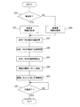
なお、図4は、突入電流等情報のうち突入電流を更新するための取得制御を示すフローチャートであり、以下、突入電流を更新する場合を例に取得制御を説明する。
そして、図4に示す情報の取得制御が電子制御装置9(CPU)にて起動されると、現在、記憶部13に記憶されている各電動モータ1A等毎の突入電流が取得された後(S15)、その取得された突入電流が電子制御装置9のRAM等に保管される(S17)。
FIG. 4 is a flowchart showing the acquisition control for updating the inrush current in the information such as the inrush current. Hereinafter, the acquisition control will be described taking the case of updating the inrush current as an example.
When the information acquisition control shown in FIG. 4 is activated by the electronic control unit 9 (CPU), the inrush current for each
次に、駆動回路1B等から電動モータ1A等に供給される電力に基づいて、各電動モータ1A等毎の実際の突入電流が測定され(S19)、S19にて測定された突入電流(以下、この電流を測定電流値という。)がRAMに保管されている突入電流(以下、この電流を保管値という。)より大きいか否かが各電動モータ1A等毎に判定される(S21)。
Next, the actual inrush current for each
そして、測定電流値が保管値より大きいと判定された場合には(S21:YES)、現在の保管値が測定電流値に更新された後(S23)、突入状態が終了したか否か、つまり電動モータ1A等が定常状態となって電流が安定したか否かが判定される(S25)。
If it is determined that the measured current value is larger than the stored value (S21: YES), after the current stored value is updated to the measured current value (S23), whether or not the inrush state has ended, that is, It is determined whether the
因みに、本実施形態では、測定電流の変化率、つまり前回測定した測定電流値と今回測定した測定電流値との差の絶対値が所定値以下となったときに、電流が安定して突入状態が終了したものと判定している。 Incidentally, in this embodiment, when the rate of change of the measured current, that is, the absolute value of the difference between the measured current value measured last time and the measured current value measured this time is equal to or less than a predetermined value, the current is stably inrushed. Is determined to have ended.
そして、S25にて突入状態が終了していないと判定された場合には(S25:NO)、S19が再び実行され、一方、突入状態が終了したと判定された場合には(S25:YES)、保管値を突入電流として記憶部13に記憶し、突入電流を更新する(S27)。
If it is determined in S25 that the rush state has not ended (S25: NO), S19 is executed again. On the other hand, if it is determined that the rush state has ended (S25: YES) The stored value is stored in the
このため、本実施形態では、次回、調整部制御が起動されたときには、更新された新しい突入電流等情報が読み込まれて駆動制御パターンが決定される。
4.本実施形態に係るシートの特徴
本実施形態では、最大作動時間となった電動モータ(最大作動時間モータ)を最初に起動するので、電源部11の電流容量を超えない範囲で、最大作動時間モータ以外の他の電動モータ1A等を最大作動時間モータと同時に作動させた場合、複数の電動モータ1A等を同時に作動させる時間を長くすることが可能となり、作動完了時間の短縮を図ることが可能となる。
For this reason, in the present embodiment, when the adjustment unit control is activated next time, the updated new inrush current information is read to determine the drive control pattern.
4). Characteristics of Seat According to this Embodiment In this embodiment, since the electric motor (maximum operation time motor) that has reached the maximum operation time is started first, the maximum operation time motor is within a range that does not exceed the current capacity of the
すなわち、図5は従来の技術における駆動制御パターンを示しており、図3(a)〜図3(d)は、本実施形態における駆動制御パターンを示している。これらの図から明らかなように、本実施形態では、最大作動時間以内で全ての電動モータ1A等の作動が完了しているのに対して、図5に示す従来の技術における駆動制御パターンでは、最大作動時間以内で全ての電動モータ1A等の作動を完了させることができない。
That is, FIG. 5 shows a drive control pattern in the prior art, and FIGS. 3A to 3D show a drive control pattern in the present embodiment. As is clear from these figures, in the present embodiment, the operation of all the
以上のように、本実施形態では、電源部11の大型化及び製造原価上昇を抑制しつつ、作動完了時間を特許文献1に記載の発明より短縮することが可能となる。
なお、「最大作動時間モータを最初に起動する」とは、最大作動時間モータより先に起動させる電動モータが無いという意味である。したがって、図3(a)及び図3(d)に示すように、最大作動時間モータを起動した後に他の電動モータ1A等を起動させる場合は勿論、全ての電動モータ1A等を同時に起動する場合も含まれる。
As described above, in the present embodiment, the operation completion time can be shortened from the invention described in Patent Document 1 while suppressing an increase in the size of the
Note that “starting the maximum operating time motor first” means that there is no electric motor to start before the maximum operating time motor. Therefore, as shown in FIGS. 3 (a) and 3 (d), when starting the other
また、本実施形態では、電動モータ1A等(姿勢調整部1等)毎に、突入電流、突入時間、作動電流及び作動速度を検出して、これら突入電流等情報を更新するので、突入電流等情報が経年変化により変化しても、最大作動時間モータを正確に特定することができる。
In the present embodiment, for each
したがって、本実施形態では、経年変化の影響を受けることなく、安定的に作動完了時間を短縮することができる。
5.発明特定事項と実施形態との対応関係
本実施形態では、検出部1C等が特許請求の範囲に記載された状態検出手段に相当し、S5が特許請求の範囲に記載された読込手段に相当し、S7が特許請求の範囲に記載された作動時間算出手段に相当し、電子制御装置9が特許請求の範囲に記載された制御部に相当し、S19が特許請求の範囲に記載された突入電流等検出手段に相当し、S27が特許請求の範囲に記載された書込手段に相当する。
Therefore, in this embodiment, the operation completion time can be stably shortened without being affected by aging.
5). Correspondence between Invention Specific Items and Embodiments In this embodiment, the
(第2実施形態)
第1実施形態では、シートに運転者等が着座しているか否かを問わず、調整部制御を実行したが、本実施形態は、シートに運転者等が着座しているか否かに応じて、参照すべき突入電流等情報を選択して駆動制御パターンを算出するものである。
(Second Embodiment)
In the first embodiment, the adjustment unit control is executed regardless of whether the driver or the like is seated on the seat. However, the present embodiment is based on whether or not the driver or the like is seated on the seat. The drive control pattern is calculated by selecting information such as the inrush current to be referred to.
このため、本実施形態に係る電動シートでは、図6に示すように、運転者等の乗員がシートに着座しているか否かを判定するための乗員判定部17が設けられているとともに、乗員が着座している場合に用いる突入電流等情報及び乗員が着座していない場合に用いる突入電流等情報が記憶部13に予め記憶されている。
For this reason, in the electric seat according to the present embodiment, as shown in FIG. 6, an
なお、本実施形態に係る乗員判定部17は、シートの座部等に設けられた圧力センサにより、乗員がシートに着座しているか否かを判定しており、乗員判定部17の出力信号は電子制御装置9に入力されている。
The
1.姿勢調整部の制御
図7は本実施形態に係る調整部制御を示すフローチャートであり、この調整部制御が起動されると、先ず、乗員判定部17の出力信号に基づいて、乗員が着座しているか否かが判定される(S31)。
1. FIG. 7 is a flowchart showing the adjustment unit control according to the present embodiment. When this adjustment unit control is activated, first, an occupant is seated based on the output signal of the
そして、着座していると判定された場合には(S31:YES)、乗員が着座している場合に用いる突入電流等情報が記憶部13から取得され(S33)、一方、着座していないと判定された場合には(S31:NO)、乗員が着座していない場合に用いる突入電流等情報が記憶部13から取得される(S35)。 If it is determined that the user is seated (S31: YES), information such as an inrush current used when the passenger is seated is acquired from the storage unit 13 (S33). If it is determined (S31: NO), information such as inrush current used when the occupant is not seated is acquired from the storage unit 13 (S35).
次に、検出部1C等からの検出信号(各電動モータ1A等の現在位置)が取得されるとともに(S37)、目標運転姿勢(電動モータ1A等の作動完了位置)が電子制御装置9のROM又は記憶部13から取得された後(S39)、S33又はS35にて取得された突入電流等情報、S39にて取得された目標運転姿勢、及びS37にて取得された現在の位置に基づいて、現在のシート状態を目標運転姿勢とするために必要な作動時間(突入時間も含む。)が、各電動モータ1A等毎に算出される(S41)。
Next, a detection signal (current position of each
そして、必要な作動時間が各電動モータ1A等毎に算出されると(S41)、少なくとも、算出された作動時間のうち最大作動時間となった電動モータを最初に作動させるような駆動制御パターンが決定された後(S43)、その決定された駆動制御パターンに従って各電動モータ1A等が駆動制御される(S45)。
When the required operation time is calculated for each
次に、各電動モータ1A等の駆動が開始されると(S45)、全ての電動モータ1A等について駆動が終了したか否かが判定され(S47)、終了していないと判定された場合には(S47:NO)、待機状態となり、終了したと判定された場合には(S47:YES)、本制御が終了する。
Next, when driving of each
2.突入電流等情報の取得制御
本実施形態では、2種類の突入電流等情報は、設計値が初期値として予め記憶部13に記憶されている。そして、本実施形態も第1実施形態と同様に、調整部制御が起動されると同時に、調整部制御と独立して作動する情報取得制御を起動し、記憶部13に記憶されている突入電流等情報を実際の測定値に更新する。
2. Inrush Current and Other Information Acquisition Control In this embodiment, two types of inrush current and other information are stored in advance in the
なお、図8は、突入電流等情報のうち突入電流を更新するための取得制御を示すフローチャートであり、以下、突入電流を更新する場合を例に本実施形態に係る取得制御を説明する。 FIG. 8 is a flowchart showing the acquisition control for updating the inrush current in the information such as the inrush current. Hereinafter, the acquisition control according to the present embodiment will be described taking the case of updating the inrush current as an example.
そして、図8に示す情報の取得制御が電子制御装置9(CPU)にて起動されると、先ず、乗員判定部17の出力信号に基づいて、乗員が着座しているか否かが判定される(S51)。
When the information acquisition control shown in FIG. 8 is activated by the electronic control unit 9 (CPU), it is first determined whether or not an occupant is seated based on the output signal of the
次に、着座していると判定された場合には(S51:YES)、乗員が着座している場合に用いる突入電流が記憶部13から取得され(S53)、一方、着座していないと判定された場合には(S51:NO)、乗員が着座していない場合に用いる突入電流が記憶部13から取得される(S55)。 Next, when it is determined that the user is seated (S51: YES), the inrush current used when the passenger is seated is acquired from the storage unit 13 (S53), and on the other hand, it is determined that the user is not seated. If it is determined (S51: NO), the inrush current used when the occupant is not seated is acquired from the storage unit 13 (S55).
そして、S53又はS55にて取得された突入電流が電子制御装置9のRAM等に保管された後(S57)、駆動回路1B等から電動モータ1A等に供給される電力に基づいて、各電動モータ1A等毎の実際の突入電流が測定される(S59)。
Then, after the inrush current acquired in S53 or S55 is stored in the RAM or the like of the electronic control device 9 (S57), each electric motor is based on the electric power supplied from the
次に、S59にて測定された測定電流値が保管値より大きいか否かが各電動モータ1A等毎に判定され(S61)、測定電流値が保管値より大きいと判定された場合には(S61:YES)、現在の保管値が測定電流値に更新された後(S63)、突入状態が終了したか否か、つまり電動モータ1A等が定常状態となって電流が安定したか否かが判定される(S65)。
Next, whether or not the measured current value measured in S59 is larger than the stored value is determined for each
そして、S65にて突入状態が終了していないと判定された場合には(S65:NO)、S59が再び実行され、一方、突入状態が終了したと判定された場合には(S65:YES)、乗員が着座しているか否かが判定される(S67)。 If it is determined in S65 that the entry state has not ended (S65: NO), S59 is executed again. On the other hand, if it is determined that the entry state has ended (S65: YES) It is then determined whether or not an occupant is seated (S67).
このとき、乗員が着座していると判定された場合には(S67:YES)、乗員が着座しているときの突入電流であることを識別可能な状態として保管値を記憶部13に記憶・更新する(S69)。
At this time, when it is determined that the occupant is seated (S67: YES), the storage value is stored in the
一方、乗員が着座していないと判定された場合には(S67:NO)、乗員が着座していないときの突入電流であることを識別可能な状態として保管値を記憶部13に記憶・更新する(S71)。
On the other hand, if it is determined that the occupant is not seated (S67: NO), the stored value is stored / updated in the
なお、本実施形態では、乗員が着座しているときの突入電流を記憶する領域と乗員が着座していないときの突入電流を記憶する領域とを異なる領域とすることで、いずれの状態の突入電流であるかを識別可能としている。 In the present embodiment, the area for storing the inrush current when the occupant is seated is different from the area for storing the rush current when the occupant is not seated. It is possible to identify whether the current is current.
3.本実施形態に係るシートの特徴
突入電流等情報は、電動モータ1A等の負荷、つまり、乗員が着座しているか否によって変化するおそれが高い。
3. Characteristics of Seat According to this Embodiment Information on inrush current or the like is likely to change depending on the load of the
しかし、本実施形態では、シートに乗員が着座しているか否かに応じて、参照すべき突入電流等情報を選択して駆動制御パターンを算出するので、乗員が着座しているか否の影響を受けることなく、安定的に作動完了時間を短縮することができる。 However, in this embodiment, since the drive control pattern is calculated by selecting information such as inrush current to be referred to depending on whether or not the occupant is seated on the seat, the influence of whether or not the occupant is seated is calculated. The operation completion time can be stably shortened without receiving.
4.発明特定事項と実施形態との対応関係
本実施形態では、S39が特許請求の範囲に記載された読込手段に相当し、S41が特許請求の範囲に記載された作動時間算出手段に相当し、S59が特許請求の範囲に記載された突入電流等検出手段に相当し、S69及びS71が特許請求の範囲に記載された書込手段に相当する。
4). Correspondence between Invention Specific Items and Embodiments In this embodiment, S39 corresponds to the reading means described in the claims, S41 corresponds to the operation time calculation means described in the claims, and S59. Corresponds to the inrush current detection means described in the claims, and S69 and S71 correspond to the writing means described in the claims.
(第3実施形態)
上述の実施形態では、記憶部13や電子制御装置9のRAM等のように、車両に搭載された記憶手段に目標運転姿勢、つまり電動モータ1A等の作動完了位置が記憶されていたが、本実施形態は、図9に示すように、無線通信を介して運転者等の乗員が携帯している記憶装置19Bに記憶された目標運転姿勢を読み込むことにより、現在のシート状態を目標運転姿勢とするために必要な作動時間を算出するものである。
(Third embodiment)
In the above-described embodiment, the target driving posture, that is, the operation completion position of the
なお、記憶装置19Bとは、例えば、車両のドア等を施錠・解除を無線通信にて実行する機能、又は車両エンジンの始動・イグニッションスイッチの投入等を無線通信にて実行する機能を有する遠隔操作装置に内蔵された携帯型の記憶装置、携帯電話、ICカードに内蔵された記憶装置等をいう。
The
このため、電子制御装置9には、記憶装置19Bとの間で無線通信を行うための無線通信装置19Aが接続されている。
なお、図10に示す制御は、本実施形態における調整部制御又は取得制御時において実行される目標運転姿勢の取得作動、つまり図2のS5(図2参照)や図7のS39等に相当する作動の詳細を示すフローチャートである。
For this reason, the electronic control device 9 is connected to a wireless communication device 19A for performing wireless communication with the
Note that the control shown in FIG. 10 corresponds to the target driving posture acquisition operation executed at the time of adjustment unit control or acquisition control in this embodiment, that is, S5 in FIG. 2 (see FIG. 2), S39 in FIG. It is a flowchart which shows the detail of an action | operation.
そして、図10に示すように、本実施形態における調整部制御又は取得制御時において目標運転姿勢の取得作動が実行されると、無線通信可能な記憶装置19B(携帯機)が探索され(S73)、無線通信可能な記憶装置19B(携帯機)が発見されて無線通信が成立すると(S73:YES)、その無線通信が成立した記憶装置19B(携帯機)から突入電流等情報が取得される(S75)。
As shown in FIG. 10, when the acquisition operation of the target driving posture is executed during the adjustment unit control or acquisition control in the present embodiment, the
(第4実施形態)
上述の実施形態では、各電動モータ1A等毎に必要な作動時間を算出し、その算出された作動時間のうち最大作動時間となった電動モータを最初に作動させるような駆動制御パターンを演算したが、本実施形態は、姿勢調整部1等のうち最も調整幅が大きい姿勢調整部を駆動する電動モータを最初に作動させる駆動制御パターンを演算し、その演算決定された駆動制御パターンに従って、各電動モータ1A等を駆動制御するものである。
(Fourth embodiment)
In the above-described embodiment, a required operation time is calculated for each
1.調整部制御
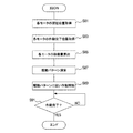
図11は本実施形態に係る調整部制御を示すフローチャートであり、この調整部制御が起動されると、先ず、検出部1C等からの検出信号、つまり各電動モータ1A等の現在位置が取得される(S81)。
1. Adjustment Unit Control FIG. 11 is a flowchart showing the adjustment unit control according to this embodiment. When this adjustment unit control is activated, first, a detection signal from the
次に、目標運転姿勢(電動モータ1A等の作動完了位置)が電子制御装置9のROMや記憶部13又は記憶装置19Bから取得された後(S83)、S83にて取得された目標運転姿勢、及びS81にて取得された現在の位置に基づいて、現在のシート状態を目標運転姿勢とするために移動量が各電動モータ1A等毎に算出される(S85)。
Next, after the target driving posture (operation completion position of the
そして、必要な移動量が各電動モータ1A等毎に算出されると(S85)、姿勢調整部1等のうち最も調整幅の大きい電動モータを最初に作動させる駆動制御パターンが決定された後(S87)、その決定された駆動制御パターンに従って各電動モータ1A等が駆動制御される(S89)。
When the necessary movement amount is calculated for each
ここで、「最も調整幅が大きい姿勢調整部」とは、調整可能な範囲が最も大きい姿勢調整部を意味しており、通常、前後方向の調整幅が最も大きいので、本実施形態では、スライド位置調整部7用の電動モータ7Aが最初に駆動される駆動制御パターンが決定される。
Here, the “posture adjustment unit with the largest adjustment width” means the posture adjustment unit with the largest adjustable range, and usually has the largest adjustment width in the front-rear direction. A drive control pattern in which the
次に、各電動モータ1A等の駆動が開始されると(S89)、全ての電動モータ1A等について駆動が終了したか否かが判定され(S91)、終了していないと判定された場合には(S91:NO)、待機状態となり、終了したと判定された場合には(S91:YES)、本制御が終了する。
Next, when driving of each
2.本実施形態に係るシートの特徴
姿勢調整部1等の調整幅、つまり調整可能な範囲は、姿勢調整部1等の構造によって決定する固定値であり、図3(a)〜図3(d)に示すように、多くの場合は、最も調整幅が大きい姿勢調整部の作動時間が最も長くなる。
2. Characteristics of Sheet According to the Present Embodiment The adjustment width of the posture adjusting unit 1 or the like, that is, the adjustable range is a fixed value determined by the structure of the posture adjusting unit 1 or the like, and is shown in FIGS. In many cases, the operation time of the posture adjustment unit having the largest adjustment width is the longest.
そこで、本実施形態では、姿勢調整部1等のうち最も調整幅が大きい姿勢調整部を駆動する電動モータを最初に作動させることで、最大作動時間を算出するための制御ステップを廃止して、調整部制御を簡素なロジックとしながら、電源部11の大型化及び製造原価上昇を抑制しつつ、作動完了時間を特許文献1に記載の発明より短縮することが可能としている。
Therefore, in the present embodiment, by first operating the electric motor that drives the posture adjustment unit having the largest adjustment width among the posture adjustment unit 1 and the like, the control step for calculating the maximum operation time is abolished, It is possible to shorten the operation completion time from the invention described in Patent Document 1 while suppressing the enlargement of the
(その他の実施形態)
上述の実施形態では、突入電流等情報等を常に更新したが、本発明はこれに限定されるものではなく、取得制御を実行しない、又は突入電流等情報を実際に測定した後、その測定値と既に記憶部13に記憶されている突入電流等情報とが相違している場合には、記憶部13に記憶されている突入電流等情報を実際の測定値に更新するような取得制御としてもよい。
(Other embodiments)
In the above-described embodiment, the information such as inrush current is constantly updated, but the present invention is not limited to this, and the measurement value is not obtained after the acquisition control is not executed or the information such as inrush current is actually measured. And the inrush current information stored in the
ところで、作動時間が決定すると、これに対応する姿勢調整部1等の移動量(具体的な調整幅)が一義的に決定するので、姿勢調整部1等の移動量(具体的な調整幅)が最も大きい電動モータ1A等が最大作動時間モータとなる。
By the way, when the operation time is determined, the movement amount (specific adjustment width) of the posture adjustment unit 1 or the like corresponding to the operation time is uniquely determined. Therefore, the movement amount (specific adjustment width) of the posture adjustment unit 1 or the like. The
したがって、第1及び第2実施形態では、直接的に作動時間を演算し、この演算された作動時間に基づいて駆動制御パターンを決定したが、本発明はこれに限られるものではなく、姿勢調整部1等の移動量を演算することにより、間接的に最大作動時間モータを特定し、姿勢調整部1等の移動量に基づいて駆動制御パターンを決定しても第1、2実施形態と同様な効果を得ることができる。 Therefore, in the first and second embodiments, the operation time is directly calculated, and the drive control pattern is determined based on the calculated operation time. However, the present invention is not limited to this, and the posture adjustment is performed. Even if the maximum operating time motor is indirectly specified by calculating the movement amount of the part 1 etc. and the drive control pattern is determined based on the movement amount of the attitude adjustment part 1 etc., the same as in the first and second embodiments Effects can be obtained.
上述の実施形態では、運転者用の電動シートに本発明を適用したが、本発明の適用はこれに限定されるものではない。
また、本発明は、特許請求の範囲に記載された発明の趣旨に合致するものであればよく、上述の実施形態に限定されるものではない。
In the above-described embodiment, the present invention is applied to the electric seat for the driver, but the application of the present invention is not limited to this.
Further, the present invention is not limited to the above-described embodiment as long as it matches the gist of the invention described in the claims.
1…フロントバーチカル姿勢調整部、1…姿勢調整部、1B…駆動回路、
1C…検出部、3…リフター姿勢調整部、3C…検出部、
5…リクライニング姿勢調整部、5C…検出部、7…スライド位置調整部、
7A…電動モータ、7C…検出部、9…電子制御装置、11…電源部、
13…記憶部、15…手動操作部、17…乗員判定部、19A…無線通信装置、
19B…記憶装置。
DESCRIPTION OF SYMBOLS 1 ... Front vertical attitude | position adjustment part, 1 ... Attitude adjustment part, 1B ... Drive circuit,
1C: detecting unit, 3 ... lifter posture adjusting unit, 3C: detecting unit,
5 ... Reclining posture adjustment unit, 5C ... Detection unit, 7 ... Slide position adjustment unit,
7A ... Electric motor, 7C ... Detection part, 9 ... Electronic control unit, 11 ... Power supply part,
DESCRIPTION OF
19B: Storage device.
Claims (6)
前記複数の電動モータに電力を供給する電源部と、
前記電動モータ各々の突入電流、突入時間、作動電流及び作動速度が記憶される記憶部と、
前記複数の姿勢調整部各々の現在の状態を検出する状態検出手段と、
目標とする姿勢を読み込む読込手段と、
前記記憶部に記憶されている突入電流、突入時間、作動電流及び作動速度、前記読込手段により読み込まれた目標姿勢状態、並びに前記状態検出手段により検出された現在の状態に基づいて、突入時間も含めた前記現在の状態を前記目標姿勢状態とするために必要な作動時間を、前記電動モータ毎に求める作動時間算出手段と、
前記複数の電動モータの作動を制御するとともに、前記作動時間算出手段により求められた作動時間のうち最大作動時間となった前記電動モータを最初に作動させる制御部と
を備えることを特徴とする車両用電動シート。 A vehicle having a plurality of posture adjustment units for maintaining the posture of an occupant operating the vehicle and changing the posture, and a plurality of electric motors for driving each of the plurality of posture adjustment units Electric seat for
A power supply for supplying power to the plurality of electric motors;
A storage unit for storing the inrush current, the inrush time, the operating current, and the operating speed of each of the electric motors;
State detection means for detecting a current state of each of the plurality of posture adjustment units;
A reading means for reading a target posture;
Based on the inrush current, the inrush time, the operating current and the operating speed, the target posture state read by the reading means, and the current state detected by the state detecting means, the inrush time is also stored in the storage unit. An operation time calculating means for obtaining, for each electric motor, an operation time necessary for setting the current state including the target posture state;
And a controller that controls the operation of the plurality of electric motors and that first operates the electric motor that has reached the maximum operation time among the operation times obtained by the operation time calculation means. Electric seat.
前記突入電流等検出手段の検出結果を前記記憶部に記憶させる書込手段と
を備えることを特徴とする請求項1に記載の車両用電動シート。 For each electric motor, inrush current, inrush time, operating current and detecting means for detecting operating speed and operating speed, etc.
The vehicle electric seat according to claim 1, further comprising: a writing unit that stores a detection result of the inrush current detection unit in the storage unit.
乗員が着座しているか否かを検出する着座検出手段と、
乗員が着座している場合の前記突入電流等検出手段の検出結果であるか、又は乗員が着座していない場合の前記突入電流等検出手段の検出結果であるかを識別可能として前記記憶部に記憶させる書込手段とを備え、
前記作動時間算出手段は、前記着座検出手段の検出結果に応じた突入電流、突入時間、作動電流及び作動速度を前記記憶部から読み込んで前記作動時間を求めることを特徴とする請求項1に記載の車両用電動シート。 For each electric motor, inrush current, inrush time, operating current and detecting means for detecting operating speed and operating speed, etc.
Seating detection means for detecting whether or not an occupant is seated;
It is possible to identify whether it is a detection result of the inrush current detection means when the occupant is seated or a detection result of the inrush current detection means when the occupant is not seated in the storage unit. Writing means for storing,
2. The operation time calculation unit reads the inrush current, the inrush time, the operation current, and the operation speed according to the detection result of the seating detection unit from the storage unit to obtain the operation time. Electric seat for vehicles.
前記読込手段は、前記ポジションメモリに記憶された姿勢を前記目標姿勢状態として読み込むことを特徴とする請求項1ないし3のいずれか1つに記載の車両用電動シート。 It has a position memory that stores the target posture,
4. The vehicle electric seat according to claim 1, wherein the reading unit reads the posture stored in the position memory as the target posture state. 5.
前記複数の電動モータに電力を供給する電源部と、
前記複数の姿勢調整部各々の現在の状態を検出する状態検出手段と、
目標とする姿勢を読み込む読込手段と、
前記複数の電動モータの作動を制御するとともに、前記複数の姿勢調整部のうち最も調整幅が大きい姿勢調整部を駆動する前記電動モータを最初に作動させる制御部と
を備えることを特徴とする車両用電動シート。 A vehicle having a plurality of posture adjustment units for maintaining the posture of an occupant operating the vehicle and changing the posture, and a plurality of electric motors for driving each of the plurality of posture adjustment units Electric seat for
A power supply for supplying power to the plurality of electric motors;
State detection means for detecting a current state of each of the plurality of posture adjustment units;
A reading means for reading a target posture;
And a controller that controls the operation of the plurality of electric motors and that first activates the electric motor that drives the posture adjustment unit having the largest adjustment width among the plurality of posture adjustment units. Electric seat.
Priority Applications (1)
| Application Number | Priority Date | Filing Date | Title |
|---|---|---|---|
| JP2008180202A JP5368020B2 (en) | 2008-07-10 | 2008-07-10 | Electric seat for vehicle |
Applications Claiming Priority (1)
| Application Number | Priority Date | Filing Date | Title |
|---|---|---|---|
| JP2008180202A JP5368020B2 (en) | 2008-07-10 | 2008-07-10 | Electric seat for vehicle |
Publications (2)
| Publication Number | Publication Date |
|---|---|
| JP2010018152A true JP2010018152A (en) | 2010-01-28 |
| JP5368020B2 JP5368020B2 (en) | 2013-12-18 |
Family
ID=41703484
Family Applications (1)
| Application Number | Title | Priority Date | Filing Date |
|---|---|---|---|
| JP2008180202A Active JP5368020B2 (en) | 2008-07-10 | 2008-07-10 | Electric seat for vehicle |
Country Status (1)
| Country | Link |
|---|---|
| JP (1) | JP5368020B2 (en) |
Cited By (4)
| Publication number | Priority date | Publication date | Assignee | Title |
|---|---|---|---|---|
| JP2015020558A (en) * | 2013-07-18 | 2015-02-02 | トヨタ紡織株式会社 | Seat device |
| KR20160050142A (en) * | 2014-10-28 | 2016-05-11 | 대성전기공업 주식회사 | Apparatus for multi switch relay |
| CN110785314A (en) * | 2017-04-28 | 2020-02-11 | 提爱思科技股份有限公司 | Seat unit, vehicle, and seat for vehicle |
| US11198379B2 (en) | 2017-04-28 | 2021-12-14 | Ts Tech Co., Ltd. | Seat unit, vehicle, and conveyance seat |
Families Citing this family (2)
| Publication number | Priority date | Publication date | Assignee | Title |
|---|---|---|---|---|
| CN104553911B (en) * | 2014-12-24 | 2019-04-23 | 延锋伟世通电子科技(上海)有限公司 | Automobile can remember the detection method of ripple of DC Moto of automatic seat |
| CN105978408A (en) * | 2016-06-20 | 2016-09-28 | 广东东箭汽车用品制造有限公司 | Electric control device for car seat and car seat |
Citations (2)
| Publication number | Priority date | Publication date | Assignee | Title |
|---|---|---|---|---|
| JPS608146U (en) * | 1983-06-29 | 1985-01-21 | 三菱自動車工業株式会社 | Power seat motor operation control device |
| JP2005313718A (en) * | 2004-04-27 | 2005-11-10 | Aisin Seiki Co Ltd | Occupant protection device for vehicle |
-
2008
- 2008-07-10 JP JP2008180202A patent/JP5368020B2/en active Active
Patent Citations (2)
| Publication number | Priority date | Publication date | Assignee | Title |
|---|---|---|---|---|
| JPS608146U (en) * | 1983-06-29 | 1985-01-21 | 三菱自動車工業株式会社 | Power seat motor operation control device |
| JP2005313718A (en) * | 2004-04-27 | 2005-11-10 | Aisin Seiki Co Ltd | Occupant protection device for vehicle |
Cited By (5)
| Publication number | Priority date | Publication date | Assignee | Title |
|---|---|---|---|---|
| JP2015020558A (en) * | 2013-07-18 | 2015-02-02 | トヨタ紡織株式会社 | Seat device |
| KR20160050142A (en) * | 2014-10-28 | 2016-05-11 | 대성전기공업 주식회사 | Apparatus for multi switch relay |
| KR101638697B1 (en) * | 2014-10-28 | 2016-07-12 | 대성전기공업 주식회사 | Apparatus for multi switch relay |
| CN110785314A (en) * | 2017-04-28 | 2020-02-11 | 提爱思科技股份有限公司 | Seat unit, vehicle, and seat for vehicle |
| US11198379B2 (en) | 2017-04-28 | 2021-12-14 | Ts Tech Co., Ltd. | Seat unit, vehicle, and conveyance seat |
Also Published As
| Publication number | Publication date |
|---|---|
| JP5368020B2 (en) | 2013-12-18 |
Similar Documents
| Publication | Publication Date | Title |
|---|---|---|
| JP5368020B2 (en) | Electric seat for vehicle | |
| JP4821363B2 (en) | Battery pack control apparatus and battery pack control method | |
| EP1705466A1 (en) | Vehicle occupant discriminating system | |
| KR101753999B1 (en) | Apparatus for controlled power seat of vehicle and method thereof | |
| US10293711B2 (en) | Device and method for controlling vehicle seat | |
| CN105150965A (en) | Automobile seat adjusting method and device | |
| CN104570919A (en) | Control device for automatically starting warm-up | |
| JP5130694B2 (en) | Power storage device used for vehicle power supply device and vehicle power supply device | |
| CN104871016A (en) | Method for setting up a current sensor | |
| JP2007261433A (en) | Battery control device and battery control method | |
| JP2716209B2 (en) | How to operate a car air purifier | |
| JP2004125594A (en) | Vehicle occupant detector | |
| JP6920238B2 (en) | Power supply controller | |
| KR20210058228A (en) | Module for preventing airbag undeployment in airbag system and method thereof | |
| JP2012111297A (en) | Airbag control device | |
| KR101832278B1 (en) | Method for diagnosing engine off timer | |
| JP2007131133A (en) | Power source device for vehicle | |
| JP5203496B2 (en) | Battery state detection method, battery state detection device, and battery power supply system | |
| JP2018176924A (en) | Control device for vehicle | |
| JP2004345473A (en) | Vehicle height adjusting device | |
| JP2005223988A (en) | Method of charging squib | |
| JP2010023811A (en) | Position change device | |
| JP5347311B2 (en) | Circuit equipment | |
| JP2018159624A (en) | Battery state estimation device | |
| JP2007176210A (en) | Controlling device for vehicle power source |
Legal Events
| Date | Code | Title | Description |
|---|---|---|---|
| A621 | Written request for application examination |
Free format text: JAPANESE INTERMEDIATE CODE: A621 Effective date: 20110513 |
|
| A977 | Report on retrieval |
Free format text: JAPANESE INTERMEDIATE CODE: A971007 Effective date: 20130214 |
|
| A131 | Notification of reasons for refusal |
Free format text: JAPANESE INTERMEDIATE CODE: A131 Effective date: 20130219 |
|
| A521 | Request for written amendment filed |
Free format text: JAPANESE INTERMEDIATE CODE: A523 Effective date: 20130410 |
|
| A131 | Notification of reasons for refusal |
Free format text: JAPANESE INTERMEDIATE CODE: A131 Effective date: 20130611 |
|
| A521 | Request for written amendment filed |
Free format text: JAPANESE INTERMEDIATE CODE: A523 Effective date: 20130722 |
|
| TRDD | Decision of grant or rejection written | ||
| A01 | Written decision to grant a patent or to grant a registration (utility model) |
Free format text: JAPANESE INTERMEDIATE CODE: A01 Effective date: 20130820 |
|
| A61 | First payment of annual fees (during grant procedure) |
Free format text: JAPANESE INTERMEDIATE CODE: A61 Effective date: 20130912 |
|
| R150 | Certificate of patent or registration of utility model |
Ref document number: 5368020 Country of ref document: JP Free format text: JAPANESE INTERMEDIATE CODE: R150 Free format text: JAPANESE INTERMEDIATE CODE: R150 |
|
| R250 | Receipt of annual fees |
Free format text: JAPANESE INTERMEDIATE CODE: R250 |
|
| R250 | Receipt of annual fees |
Free format text: JAPANESE INTERMEDIATE CODE: R250 |
|
| R250 | Receipt of annual fees |
Free format text: JAPANESE INTERMEDIATE CODE: R250 |
|
| R250 | Receipt of annual fees |
Free format text: JAPANESE INTERMEDIATE CODE: R250 |
|
| R250 | Receipt of annual fees |
Free format text: JAPANESE INTERMEDIATE CODE: R250 |
|
| R250 | Receipt of annual fees |
Free format text: JAPANESE INTERMEDIATE CODE: R250 |
|
| R250 | Receipt of annual fees |
Free format text: JAPANESE INTERMEDIATE CODE: R250 |
|
| R250 | Receipt of annual fees |
Free format text: JAPANESE INTERMEDIATE CODE: R250 |