JP2010017765A - Powder compacting press machine - Google Patents
Powder compacting press machine Download PDFInfo
- Publication number
- JP2010017765A JP2010017765A JP2009046289A JP2009046289A JP2010017765A JP 2010017765 A JP2010017765 A JP 2010017765A JP 2009046289 A JP2009046289 A JP 2009046289A JP 2009046289 A JP2009046289 A JP 2009046289A JP 2010017765 A JP2010017765 A JP 2010017765A
- Authority
- JP
- Japan
- Prior art keywords
- powder lubricant
- powder
- lubricant
- mortar
- charging device
- Prior art date
- Legal status (The legal status is an assumption and is not a legal conclusion. Google has not performed a legal analysis and makes no representation as to the accuracy of the status listed.)
- Granted
Links
- 239000000843 powder Substances 0.000 title claims abstract description 165
- 239000000314 lubricant Substances 0.000 claims abstract description 141
- 239000004570 mortar (masonry) Substances 0.000 claims abstract description 76
- 239000007921 spray Substances 0.000 claims abstract description 40
- 238000011084 recovery Methods 0.000 claims abstract description 19
- 238000005507 spraying Methods 0.000 claims abstract description 15
- 238000002347 injection Methods 0.000 claims description 55
- 239000007924 injection Substances 0.000 claims description 55
- 238000000465 moulding Methods 0.000 claims description 18
- 238000009702 powder compression Methods 0.000 claims description 18
- 210000000744 eyelid Anatomy 0.000 claims description 10
- 239000003795 chemical substances by application Substances 0.000 claims description 3
- 238000011109 contamination Methods 0.000 abstract description 5
- 239000000428 dust Substances 0.000 description 21
- XEEYBQQBJWHFJM-UHFFFAOYSA-N Iron Chemical compound [Fe] XEEYBQQBJWHFJM-UHFFFAOYSA-N 0.000 description 12
- 238000001514 detection method Methods 0.000 description 10
- 238000010521 absorption reaction Methods 0.000 description 6
- 229910052742 iron Inorganic materials 0.000 description 6
- 230000002093 peripheral effect Effects 0.000 description 5
- 239000013256 coordination polymer Substances 0.000 description 3
- 238000010586 diagram Methods 0.000 description 3
- 239000002994 raw material Substances 0.000 description 3
- 238000000748 compression moulding Methods 0.000 description 2
- 239000002826 coolant Substances 0.000 description 2
- HQKMJHAJHXVSDF-UHFFFAOYSA-L magnesium stearate Chemical compound [Mg+2].CCCCCCCCCCCCCCCCCC([O-])=O.CCCCCCCCCCCCCCCCCC([O-])=O HQKMJHAJHXVSDF-UHFFFAOYSA-L 0.000 description 2
- 239000004482 other powder Substances 0.000 description 2
- 230000036316 preload Effects 0.000 description 2
- YCKRFDGAMUMZLT-UHFFFAOYSA-N Fluorine atom Chemical compound [F] YCKRFDGAMUMZLT-UHFFFAOYSA-N 0.000 description 1
- 239000006096 absorbing agent Substances 0.000 description 1
- 210000000588 acetabulum Anatomy 0.000 description 1
- 239000003814 drug Substances 0.000 description 1
- 229940079593 drug Drugs 0.000 description 1
- 238000010292 electrical insulation Methods 0.000 description 1
- 238000005530 etching Methods 0.000 description 1
- 239000011737 fluorine Substances 0.000 description 1
- 229910052731 fluorine Inorganic materials 0.000 description 1
- 235000019359 magnesium stearate Nutrition 0.000 description 1
- 238000004519 manufacturing process Methods 0.000 description 1
- 229940098458 powder spray Drugs 0.000 description 1
- 229920005989 resin Polymers 0.000 description 1
- 239000011347 resin Substances 0.000 description 1
- 229910052594 sapphire Inorganic materials 0.000 description 1
- 239000010980 sapphire Substances 0.000 description 1
- 238000007790 scraping Methods 0.000 description 1
- 229910001220 stainless steel Inorganic materials 0.000 description 1
- 239000010935 stainless steel Substances 0.000 description 1
- 229920003002 synthetic resin Polymers 0.000 description 1
- 239000000057 synthetic resin Substances 0.000 description 1
- 239000000454 talc Substances 0.000 description 1
- 229910052623 talc Inorganic materials 0.000 description 1
- XLYOFNOQVPJJNP-UHFFFAOYSA-N water Substances O XLYOFNOQVPJJNP-UHFFFAOYSA-N 0.000 description 1
Images


Classifications
-
- B—PERFORMING OPERATIONS; TRANSPORTING
- B30—PRESSES
- B30B—PRESSES IN GENERAL
- B30B15/00—Details of, or accessories for, presses; Auxiliary measures in connection with pressing
- B30B15/0005—Details of, or accessories for, presses; Auxiliary measures in connection with pressing for briquetting presses
- B30B15/0011—Details of, or accessories for, presses; Auxiliary measures in connection with pressing for briquetting presses lubricating means
-
- B—PERFORMING OPERATIONS; TRANSPORTING
- B05—SPRAYING OR ATOMISING IN GENERAL; APPLYING FLUENT MATERIALS TO SURFACES, IN GENERAL
- B05B—SPRAYING APPARATUS; ATOMISING APPARATUS; NOZZLES
- B05B5/00—Electrostatic spraying apparatus; Spraying apparatus with means for charging the spray electrically; Apparatus for spraying liquids or other fluent materials by other electric means
- B05B5/007—Electrostatic spraying apparatus; Spraying apparatus with means for charging the spray electrically; Apparatus for spraying liquids or other fluent materials by other electric means the high voltage supplied to an electrostatic spraying apparatus during spraying operation being periodical or in time, e.g. sinusoidal
-
- B—PERFORMING OPERATIONS; TRANSPORTING
- B05—SPRAYING OR ATOMISING IN GENERAL; APPLYING FLUENT MATERIALS TO SURFACES, IN GENERAL
- B05B—SPRAYING APPARATUS; ATOMISING APPARATUS; NOZZLES
- B05B1/00—Nozzles, spray heads or other outlets, with or without auxiliary devices such as valves, heating means
- B05B1/26—Nozzles, spray heads or other outlets, with or without auxiliary devices such as valves, heating means with means for mechanically breaking-up or deflecting the jet after discharge, e.g. with fixed deflectors; Breaking-up the discharged liquid or other fluent material by impinging jets
- B05B1/262—Nozzles, spray heads or other outlets, with or without auxiliary devices such as valves, heating means with means for mechanically breaking-up or deflecting the jet after discharge, e.g. with fixed deflectors; Breaking-up the discharged liquid or other fluent material by impinging jets with fixed deflectors
- B05B1/267—Nozzles, spray heads or other outlets, with or without auxiliary devices such as valves, heating means with means for mechanically breaking-up or deflecting the jet after discharge, e.g. with fixed deflectors; Breaking-up the discharged liquid or other fluent material by impinging jets with fixed deflectors the liquid or other fluent material being deflected in determined directions
-
- B—PERFORMING OPERATIONS; TRANSPORTING
- B05—SPRAYING OR ATOMISING IN GENERAL; APPLYING FLUENT MATERIALS TO SURFACES, IN GENERAL
- B05B—SPRAYING APPARATUS; ATOMISING APPARATUS; NOZZLES
- B05B5/00—Electrostatic spraying apparatus; Spraying apparatus with means for charging the spray electrically; Apparatus for spraying liquids or other fluent materials by other electric means
- B05B5/025—Discharge apparatus, e.g. electrostatic spray guns
- B05B5/03—Discharge apparatus, e.g. electrostatic spray guns characterised by the use of gas, e.g. electrostatically assisted pneumatic spraying
- B05B5/032—Discharge apparatus, e.g. electrostatic spray guns characterised by the use of gas, e.g. electrostatically assisted pneumatic spraying for spraying particulate materials
-
- B—PERFORMING OPERATIONS; TRANSPORTING
- B05—SPRAYING OR ATOMISING IN GENERAL; APPLYING FLUENT MATERIALS TO SURFACES, IN GENERAL
- B05B—SPRAYING APPARATUS; ATOMISING APPARATUS; NOZZLES
- B05B7/00—Spraying apparatus for discharge of liquids or other fluent materials from two or more sources, e.g. of liquid and air, of powder and gas
- B05B7/14—Spraying apparatus for discharge of liquids or other fluent materials from two or more sources, e.g. of liquid and air, of powder and gas designed for spraying particulate materials
- B05B7/1404—Arrangements for supplying particulate material
- B05B7/1454—Arrangements for supplying particulate material comprising means for supplying collected oversprayed particulate material
Abstract
Description
本発明は、粉末を圧縮して錠剤や電子部品等を成形するための粉末圧縮成形機に関する。 The present invention relates to a powder compression molding machine for compressing powder to form tablets, electronic parts and the like.
従来、回転式粉末圧縮成形機を用いて、医薬品錠剤を製造する場合、薬物処方成分のみで錠剤の原料粉末を構成すると、杵や臼に錠剤の原料粉末や錠剤がこびりつくといったいわゆるスティッキング等の障害が生じる場合がある。この障害を防止するため、例えばステアリン酸マグネシウムやタルクといった粉末滑沢剤を、杵表面や臼孔等のスティッキングの生じる部位に付着させ、打錠前に上杵、下杵、臼孔にあらかじめ粉末滑沢剤をスプレー塗布するようにしたものや、あるいは打錠前に粉末滑沢剤のみをダミーで圧縮し、上杵、下杵、臼孔に粉末滑沢剤が被覆されるようにしたものが考えられている。さらに、粉末滑沢剤の噴射位置において杵の端面に対向する凹面を有し、粉末滑沢剤を凹面に案内させてほぼ杵の端面の方向に噴射する噴射ノズルと、上杵の下端面近傍に空気を噴射して噴射ノズルから噴射された粉末滑沢剤の上方向への飛散を阻止する空気流供給機構と、噴射ノズルから噴射される際に粉末滑沢剤を帯電させるとともに、帯電している粉末滑沢剤とは反対極性に少なくとも上杵、下杵及び臼を帯電させる帯電装置とを具備する粉末滑沢剤噴射手段を具備させることにより、粉末滑沢剤を上杵と下杵との端面及び臼孔の内周面にほぼ均一に静電付着させ、粉末滑沢剤の付着効率を向上させることが考えられている(例えば、特許文献1を参照)。 Conventionally, when manufacturing pharmaceutical tablets using a rotary powder compression molding machine, if the raw material powder of the tablet is composed only of the drug prescription components, the so-called sticking obstacle such as the tablet raw material powder and the tablet sticking to the pestle or die May occur. In order to prevent this obstacle, a powder lubricant such as magnesium stearate or talc is attached to the surface of the heel or the acetabulum where sticking occurs, and the powder lubricant is previously applied to the upper heel, lower heel and mortar before tableting. It is possible to apply a powder spray or to compress the powder lubricant with a dummy before tableting so that the upper, lower and mortar holes are covered with the powder lubricant. It has been. In addition, a spray nozzle that has a concave surface facing the end face of the ridge at the spray position of the powder lubricant, guides the powder lubricant to the concave surface, and sprays in the direction of the end face of the heel, and near the lower end face of the upper ridge An air flow supply mechanism that prevents air powder from spraying upward from spraying from the spray nozzle and charging the powder lubricant when sprayed from the spray nozzle. The powder lubricant is provided with a powder lubricant injection means having at least an upper arm, a lower arm, and a charging device for charging the mortar with the opposite polarity to the powder lubricant. In order to improve the adhesion efficiency of the powder lubricant, it is conceivable to electrostatically adhere almost uniformly to the end face and the inner peripheral surface of the mortar (see, for example, Patent Document 1).
ところで、特許文献1記載の構成では、粉末滑沢剤を帯電させた状態で臼孔に向けて連続的に噴射させるようにしている。しかし、このような構成では、臼孔と臼孔との間の部位にも帯電した粉末滑沢剤が付着し、フィードシューにおいて原料粉末に混入し、コンタミネーションを起こす不具合が発生する。
By the way, in the structure of
本発明は、このような課題を解決すべく構成するものである。 The present invention is configured to solve such problems.
すなわち本発明に係る粉末圧縮成形機の一つは、同一の中心軸に沿って対向配置した上杵と下杵との杵先を臼孔に挿入し、その状態で上杵及び下杵を互いに接近する方向に移動させることにより臼孔に充填した粉末を圧縮成形する構成を有するとともに、粉末の充填に先立って臼孔に粉末滑沢剤を噴射する粉末滑沢剤噴射手段を具備するものであって、前記粉末滑沢剤噴射手段が、前記粉末滑沢剤を前記臼孔に向けて噴射する下向噴射ノズルと、前記粉末滑沢剤噴射手段から噴射され余剰となった前記粉末滑沢剤を回収する粉末滑沢剤回収機構と、前記下向噴射ノズルから噴射される前記粉末滑沢剤を帯電させる帯電装置と、この帯電装置に接続され前記臼孔に達するタイミングで噴射される前記粉末滑沢剤だけに帯電させるべく機能するスイッチング手段とを具備することを特徴とする。 That is, in one of the powder compression molding machines according to the present invention, the tip of the upper and lower eyelids arranged to face each other along the same central axis is inserted into the mortar hole, and in this state, the upper and lower eyelids are mutually attached. It has a configuration in which the powder filled in the mortar hole is compression-molded by moving in the approaching direction, and has a powder lubricant injection means for injecting the powder lubricant into the mortar hole prior to powder filling. The powder lubricant spraying means includes a downward spray nozzle for spraying the powder lubricant toward the mortar hole, and the powder lubricant sprayed from the powder lubricant spraying means and surplus. A powder lubricant recovery mechanism for recovering the agent, a charging device for charging the powder lubricant sprayed from the downward spray nozzle, and the sprayed at the timing of reaching the mortar hole connected to the charging device A function to charge only the powder lubricant. Characterized by comprising the etching means.
このようなものであれば、臼孔に達した粉末滑沢剤は帯電しているので、粉末滑沢剤回収機構による吸塵の空気流に抗して臼孔に付着する一方、他の部位に達した粉末滑沢剤は帯電していないので粉末滑沢剤回収機構による吸塵のための空気流により吸塵用管路に向かい吸塵機へ回収される。従って、臼孔には粉末滑沢剤を確実に付着させつつ、臼孔と臼孔との間の部位には残らないので、コンタミネーションの抑制を図ることができる。 In such a case, the powder lubricant that has reached the mortar hole is charged, so that it adheres to the mortar hole against the air flow of dust absorption by the powder lubricant recovery mechanism, while at other sites. Since the reached powder lubricant is not charged, it is recovered by the dust lubricant recovery mechanism toward the dust suction pipe by the air flow for dust collection. Accordingly, the powder lubricant is reliably adhered to the mortar, and it does not remain in the portion between the mortar and mortar, so that contamination can be suppressed.
このようなスイッチング手段を容易に実現できる構成として、前記スイッチング手段が、前記下向噴射ノズル直下に1つの臼孔が達してから次の臼孔が達するまでの間隔でパルスを発するパルス発生機構と、このパルス発生機構からパルスが出力されている時間帯にのみ前記帯電装置に通電させるスイッチ本体とを具備するものが挙げられる。 As a configuration that can easily realize such a switching means, the switching means includes a pulse generating mechanism that emits a pulse at an interval from the arrival of one mortar immediately below the downward injection nozzle to the arrival of the next mortar. And a switch body that energizes the charging device only during a time period in which a pulse is output from the pulse generation mechanism.
そして、前記粉末滑沢剤噴射手段が、前記粉末滑沢剤を前記上杵の下端部に向けて噴射する上向噴射ノズルと、前記粉末滑沢剤回収機構に向かう方向に空気を噴射し前記上向噴射ノズルから噴射された前記粉末滑沢剤の飛散を阻止する空気流供給機構と、前記上向噴射ノズルから噴射される前記粉末滑沢剤を帯電させる第2の帯電装置と、この第2の帯電装置に接続され前記上杵の下端部に達するタイミングで噴射される前記粉末滑沢剤だけに帯電させるべく機能する第2のスイッチング手段とをさらに具備するものであれば、上杵に噴射する粉末滑沢剤についても、同様に、上杵に付着させる粉末滑沢剤のみを帯電させ、その他の粉末滑沢剤は帯電させないようにすることにより、上杵には粉末滑沢剤を確実に付着させつつ、粉末滑沢剤の上杵以外への付着の抑制を図ることができる。 The powder lubricant spraying means jets air in a direction toward the powder lubricant recovery mechanism, an upward spray nozzle that sprays the powder lubricant toward the lower end of the upper punch, and An air flow supply mechanism that prevents the powder lubricant sprayed from the upward spray nozzle from being scattered; a second charging device that charges the powder lubricant sprayed from the upward spray nozzle; If it further comprises a second switching means that functions to charge only the powder lubricant that is connected to the charging device of No. 2 and reaches the lower end of the upper lid, the upper lid Similarly, for the powder lubricant to be sprayed, the powder lubricant is applied to the upper arm by charging only the powder lubricant adhering to the upper arm and not charging the other powder lubricant. Of powder lubricant while ensuring adhesion It is possible to suppress the adhesion of the non-punch.
本発明に係る粉末圧縮成形機の構成によれば、臼孔に達する粉末滑沢剤のみを帯電させるので、臼孔に達した粉末滑沢剤は粉末滑沢剤回収機構による吸塵の空気流に抗して臼孔に付着する一方、臼孔に付着しない粉末滑沢剤は帯電していないので粉末滑沢剤回収機構による吸塵の空気流により吸塵用管路に向かい吸塵機へ回収されるようにできる。従って、臼孔には粉末滑沢剤を確実に付着させつつ、コンタミネーションの抑制を図ることができる。 According to the configuration of the powder compression molding machine according to the present invention, since only the powder lubricant reaching the mortar hole is charged, the powder lubricant reaching the mortar hole is subjected to the air flow of dust absorption by the powder lubricant recovery mechanism. The powder lubricant that does not adhere to the mortar hole against the mortar hole is not charged, so it is recovered to the dust collector by the air flow of dust absorption by the powder lubricant recovery mechanism. Can be. Therefore, contamination can be suppressed while the powder lubricant is reliably attached to the mortar hole.
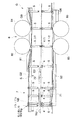
この回転式粉末圧縮成形機Aは、図1、図2、及び図3に示すように、フレーム1内に回転盤3を立シャフト2を介して回転可能に配設し、その回転盤3に複数の臼4を所定のピッチで設けるとともに、各臼4の上下に上杵5及び下杵6を上下摺動可能に保持させてある。
As shown in FIGS. 1, 2, and 3, the rotary powder compression molding machine A includes a rotating
詳述すると、フレーム1の略中央部には軸受21により軸支された立シャフト2が配設されるとともに、この立シャフト2の下端近傍にウォームホイール22が固定してあり、このウォームホイール22にウォーム23及びベルト24を介してモータ25の回転駆動力を伝達するようにしている。そして、立シャフト2の上端近傍に、3つの機能部分に分けられる回転盤3が固定してある。前記回転盤3は、上側部分に設けられて上杵5を上下摺動可能に保持する上杵保持部31と、下側部分に設けられて下杵6を上下摺動可能に保持する下杵保持部32と、これら上杵保持部31と下杵保持部32の間に設けられて、臼4を着脱可能に嵌装するための臼取付孔(図示略)を同一円周上に複数個数設けてなる臼保持部33とを具備してなる。この実施形態の回転盤3は、例えば水等の冷却媒体で冷却されるもので、成形品の熱による膨張を抑えるべくその冷却媒体が通過する流路(図示略)が臼4の近傍に設けてある。前記臼4は、臼保持部33の円周側面に設けられる臼固定機構(図示略)により臼取付孔内に取り外し可能に固定されるものである。
More specifically, a
また、この回転式粉末圧縮成形機Aには、図2及び図3に示すように、粉末充填部7と、粉末摺切部Sと、圧縮成形部8と、製品取出部Gと、粉末滑沢剤噴射部9とが、回転盤3の回転方向に沿って順次に設けてある。
In addition, as shown in FIGS. 2 and 3, the rotary powder compression molding machine A includes a
粉末充填部7は、下杵6を下杵降下器71により降下させて回転盤3上に供給された粉末をフィードシュー72により臼4の臼孔41内に導入するようにしたもので、回転盤3上への粉末の供給は、粉末供給機構73により行われる。
The
粉末摺切部Sは、分量レールS2により下杵6を所定位置まで上昇させるとともに下杵6の上昇により臼孔41から溢れ出た粉末を摺切板S3により臼4上から除去するようにしたものである。
The powder cutting part S raises the
圧縮成形部8は、上杵5を下り傾斜面に沿わせて降下させその杵先を臼孔41に挿入させるための上杵降下カム81と、杵先を臼孔41に挿入した上杵5と下杵6とを上下から拘束して臼孔41の粉末を予備的に圧縮する予圧上ロール82及び予圧下ロール83と、前記上杵5と下杵6とを上下から拘束して臼孔41の粉末を本格的に圧縮する本圧上ロール84及び本圧下ロール85とを具備してなる。
The
製品取出部Gは、図2及び図3に示すように、上杵5を上り傾斜面に沿わせて上昇させその杵先を臼孔41から抜き取るための上杵上昇カムG0と、下杵6を上方に付勢して臼孔41の製品Qを完全に臼孔41の外に押出す押上レールG6と、押出された製品Qを側方に案内してシュートG4に導く案内板G5とを具備してなる。
As shown in FIGS. 2 and 3, the product takeout part G includes an upper eyelid raising cam G0 for raising the
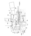
粉末滑沢剤噴射部9は、製品取出部Gと粉末充填部7との間に設けるものである。この粉末滑沢剤噴射部9は、図4に示すように、上杵5の下端面5a、下杵6の上端面6a及び臼4に設けた臼孔41の内周面に粉末滑沢剤Lを飛散を防止して供給するものであり、上杵5のための粉末滑沢剤Lが通過する貫通孔91及び空気流供給機構により供給される空気流であるエアカーテンACが吸入される吸入口92を除いて粉末滑沢剤Lが連続して噴射される空間を包囲する箱体BXを有してなり、その箱体BX内に上杵5に粉末滑沢剤Lを噴射する上向噴射ノズルNUと、下杵6及び臼孔41に粉末滑沢剤Lを噴射する下向噴射ノズルNBとの先端を内包し、貫通孔91の上方をエアカーテンACが吸入口92に向かって噴射されるように構成されている。
The powder
すなわち、粉末滑沢剤噴射部9において上杵5の下端面5a、下杵6の上端面6a及び臼4の臼孔41に粉末滑沢剤Lを供給する粉末滑沢剤噴射手段は、図4及び図5に示すように、凹面NBaを有し粉末滑沢剤Lの供給位置において下杵6の上端面6aに対向し粉末滑沢剤Lを凹面NBaに案内させてほぼ一方向に噴射する噴射ノズルたる下向噴射ノズルNBと、上杵5の下端面5a近傍に空気流を噴射して上向噴射ノズルNUから噴射されて余剰となった粉末滑沢剤Lの上方向への飛散を阻止するエアカーテンACを含む空気流供給機構とを具備するものである。下向噴射ノズルNBは箱体BXに取り付けられ、ごく微量の粉末滑沢剤Lを計量し加圧気体により圧送する粉末滑沢剤噴射装置LSに接続してある。さらに、前記下向噴射ノズルNBには、前記凹面NBaに連通するように導入孔NBcが設けてある。そして、前記下向噴射ノズルNBは、例えばフッ素樹脂製であり、そのノズル先端NB1がノズル本体NB2から取り外しできるようになっている。また、図示はしないが、この粉末滑沢剤噴射手段の上向噴射ノズルNUも前記下向噴射ノズルNBに設けたものと同様の凹面を有し、この凹面に粉末滑沢剤Lを案内させるようにしている。
That is, the powder lubricant spraying means for supplying the powder lubricant L to the
さらに、これら上向噴射ノズルNU及び下向噴射ノズルNBには、粉末滑沢剤Lを帯電させるための例えばステンレス製の電極EDがそれぞれ設けてある。具体的には、前記下向噴射ノズルNBの場合について説明すると、前記下向噴射ノズルNBのノズル先端NB1及びノズル本体NB2には、導入孔NBcと平行に配置されて連通する貫通孔NBdが設けてあり、その貫通孔NBd内にそれぞれ丸棒状の電極EDが挿入してある。前記電極EDは、その先端EDaが円錐状あるいは針状に尖らせてあり、中心軸線の延長線上に位置している。 Further, the upward spray nozzle NU and the downward spray nozzle NB are provided with, for example, stainless steel electrodes ED for charging the powder lubricant L. Specifically, the case of the downward injection nozzle NB will be described. The nozzle tip NB1 and the nozzle body NB2 of the downward injection nozzle NB are provided with through holes NBd arranged in parallel with the introduction holes NBc. A round bar-like electrode ED is inserted into each through hole NBd. The electrode ED has a tip EDa sharpened like a cone or needle, and is located on an extension line of the central axis.
一方、前記箱体BXは、例えばフッ素樹脂等の合成樹脂製で、案内板G5のフィードシュー72に対向する面に、回転盤3から電気的に絶縁された状態で固定されるものである。この箱体BXは、エアカーテンAC用空気の供給路SPが内部に設けられるとともにエアカーテンAC用の空気吹出口BX1aが設けられた第1側壁BX1と、第1側壁BX1から水平方向に固定され上杵5の対応位置に貫通孔91が設けられた第1上壁BX2と、第1上壁BX2に連続して設けられその連続する部分の近傍においてエアカーテンACを吸入する吸入口92が設けられた第2上壁BX3と、エアカーテンAC用空気を供給路SPに案内する案内路を有して案内板G5に平行になるように第1側壁BX1に固定される第2側壁BX4と、第2側壁BX4に平面視直角に取り付けられる第3側壁BX5と、臼保持部33と第1側壁BX1、上向噴射ノズルNU、下向噴射ノズルNBの下面部との間隙を封鎖する電気絶縁性を有する弾性部材BX6、BX7と、弾性部材BX6、BX7の内側に設けられて箱体BXの底部分を閉鎖する例えばフッ素樹脂製の底板BX8とからなる。
On the other hand, the box BX is made of, for example, a synthetic resin such as a fluororesin, and is fixed to a surface of the guide plate G5 facing the
この箱体BXの第3側壁BX5には、前記上向噴射ノズルNU、前記下向噴射ノズルNB、及び吸塵用管路Pが取り付けられる。第2側壁BX4の端面には、第3側壁BX5を介してエアカーテンAC用空気を導入する接続部CPが取り付けられる。底板BXの臼4の軌跡に対応する部位には、前記下向噴射ノズルNBから噴射された粉末滑沢剤Lが通る、臼孔41より若干大径の供給孔BX8aが設けてある。このような底板BX8を有することにより、粉末滑沢剤Lは、回転盤3が帯電していても、この供給孔BX8aの幅の円環状にしか回転盤3に付着することがなく、回転盤3への付着を最小限に抑えている。また、前記接続部CPには、エアカーテンACを形成するための高圧空気を発生させるエアコンプレッサ(図示しない)に接続されるもので、エアコンプレッサ、供給路SP、接続部CPにより空気流供給機構が構成されるものである。また、前記吸塵用管路Pには、吸塵機LS5が接続され、箱体BXとともに粉末滑沢剤回収機構を構成するものである。
The upward injection nozzle NU, the downward injection nozzle NB, and the dust suction pipe P are attached to the third side wall BX5 of the box BX. A connecting portion CP for introducing air for the air curtain AC is attached to the end surface of the second side wall BX4 via the third side wall BX5. A supply hole BX8a having a slightly larger diameter than the
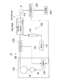
前記粉末滑沢剤噴射装置LSは、図6に示すように、モータMにより駆動される回転ドラムDの外周面に付着した粉末滑沢剤Lを空気流により送出する粉末滑沢剤供給部LS1と、粉末滑沢剤供給部LS1から供給される粉末滑沢剤Lの流量を検知する流量検知部LS2と、上向噴射ノズルNU、下向噴射ノズルNBから噴射され上杵5、下杵6及び臼孔41に付着せずに回収された粉末滑沢剤Lの量を検知する回収量検知部LS3と、流量検知部LS2と回収量検知部LS3とにおいて検知された粉末滑沢剤Lの検知量に基づいて粉末滑沢剤供給部LS1を制御する制御部LS4と、粉末滑沢剤回収機構を構成する吸塵機LS5と、粉末滑沢剤Lを帯電させるための帯電装置CDとを具備している。本実施形態では、この粉末滑沢剤噴射装置LSの上向噴射ノズルNU及び下向噴射ノズルNBから粉末滑沢剤Lを連続的に噴射するようにしている。なお、前記粉末滑沢剤回収機構の吸塵機LS5により吸引された粉末滑沢剤Lは、粉末滑沢剤供給部LS1に還流されるようにしてもよい。
As shown in FIG. 6, the powder lubricant injection device LS has a powder lubricant supply unit LS <b> 1 that sends out the powder lubricant L attached to the outer peripheral surface of the rotary drum D driven by the motor M by an air flow. And a flow rate detection unit LS2 for detecting the flow rate of the powder lubricant L supplied from the powder lubricant supply unit LS1, an upper jet nozzle NU, a downward jet nozzle NB, and the
前記帯電装置CDは、例えば0〜20Vの交流電圧を発生する電源部PSと、電源部PSから出力された交流電圧を例えば数十kVの直流高電圧に変換し出力する高電圧発生器HVと、高電圧発生器HVから出力された直流高電圧が印加されて粉末滑沢剤を帯電させる前記電極EDとからなる。なお、高電圧発生器HVの基準電位に保持される出力端子は地絡されるものであり、これに対応して少なくとも上杵5、下杵6、及び臼4は地絡されるものである。この実施形態では、回転盤3を地絡させることにより、上杵5、下杵6、及び臼4を地絡させている。また、本実施形態では、下向噴射ノズルNBに設けた前記電極EDを含む帯電装置CDと、上向噴射ノズルNUに設けた前記電極EDを含む帯電装置CDとをそれぞれ設けている。ここで、上向噴射ノズルNUに設けた前記電極EDを含む帯電装置CDは、請求項中の第2の帯電装置として機能する。
The charging device CD includes, for example, a power supply unit PS that generates an AC voltage of 0 to 20 V, a high voltage generator HV that converts the AC voltage output from the power supply unit PS into a DC high voltage of, for example, several tens of kV, and outputs it. And the electrode ED for charging the powder lubricant by applying a DC high voltage output from the high voltage generator HV. The output terminal held at the reference potential of the high voltage generator HV is grounded, and at least the
ここで、前記粉末滑沢剤噴射装置LSのうち、粉末滑沢剤供給部LS1、制御部LS4、集塵機LS5、及び前記帯電装置CDの電源部PS、高圧発生器HVは回転式粉末圧縮成形機Aの外側に設けている。一方、流量検知部LS2、回収量検知部LS3及び帯電装置CDを構成する電極EDは回転式粉末圧縮成形機A内に配設している。 Here, among the powder lubricant injection device LS, the powder lubricant supply unit LS1, the control unit LS4, the dust collector LS5, the power supply unit PS of the charging device CD, and the high pressure generator HV are a rotary powder compression molding machine. It is provided outside A. On the other hand, the flow rate detection unit LS2, the recovery amount detection unit LS3, and the electrode ED constituting the charging device CD are arranged in the rotary powder compression molding machine A.
しかして本実施形態では、前記下向噴射ノズルNBから噴射される前記粉末滑沢剤Lのうち臼孔41に達するタイミングで噴射されるもの、及び上向噴射ノズルNUから噴射される前記粉末滑沢剤Lのうち上杵5の下端部に達するものだけをそれぞれ帯電させるべく、前記帯電装置CDにスイッチング手段たるスイッチSWを接続している。ここで、前記上向噴射ノズルNU側の帯電装置CDに接続したスイッチは、請求項中の第2のスイッチとして機能する。
Therefore, in the present embodiment, among the powder lubricant L injected from the downward injection nozzle NB, the powder lubricant injected at the timing reaching the
下向噴射ノズルNB側について説明すると、このスイッチSWは、図7に概略構成を示すブロック図、図8にタイムチャートをそれぞれ示すように、下向噴射ノズルNB直下に1つの臼孔41が達してから次の臼孔41が達するまでの間隔でパルスを発するパルス発生機構SW1と、このパルス発生機構SW1からパルスが出力されている時間帯にのみ前記帯電装置CDに通電させるスイッチ本体SW2とを具備する。
Referring to the downward injection nozzle NB side, as shown in the block diagram showing the schematic configuration in FIG. 7 and the time chart in FIG. 8, the switch SW reaches one
前記パルス発生機構SW1は、前記回転盤3と同一周期で回転するとともに前記上杵5と下杵6との組と同数の突起SW12を等間隔で設けている円板SW11と、前記円板SW11に設けた突起SW12の接近を検知し突起検知信号を発するセンサSW13と、このセンサSW13から突起検知信号を受けてパルスを発するパルス発生要素SW14とを具備する。
The pulse generating mechanism SW1 rotates at the same cycle as the
一方、前記スイッチ本体SW2は、前記パルス発生要素SW14からのパルスを受け付けるパルス受信要素SW21と、このパルス受信要素SW21がパルスを受け付けている場合に帯電装置CDに通電し、その他の場合には帯電装置CDへの通電を遮断するスイッチ要素SW22とを具備する。 On the other hand, the switch body SW2 energizes the charging device CD when the pulse receiving element SW21 accepts a pulse from the pulse generating element SW14, and the pulse receiving element SW21 accepts the pulse, and is charged otherwise. And a switch element SW22 that cuts off power to the device CD.
前記パルスは、臼孔41の下向噴射ノズルNB直下通過の開始時刻から終了時刻までの時間帯T0だけ発振されるようにしている。ここで、粉末滑沢剤Lが射出されてから臼孔41に達するまでの長さの時間は無視できる程度の短時間としている。
The pulse is oscillated only during a time period T0 from the start time to the end time of the passage immediately below the downward injection nozzle NB of the
上向噴射ノズルNU側の帯電装置CDに接続したスイッチSWも、図示はしないが、同様の構成を有する。但し、前記パルスは、前記臼孔41の下向噴射ノズルNB直下通過の開始時刻から終了時刻までの時間帯T0でなく、前記上杵5の下端部の上向噴射ノズルNU直下通過の開始時刻から終了時刻までの時間帯だけ発振されるようにしている。
The switch SW connected to the charging device CD on the upward injection nozzle NU side has a similar configuration although not shown. However, the pulse is not the time zone T0 from the start time to the end time of the downward injection nozzle NB passing immediately below the
このような構成において、粉末滑沢剤Lを噴射するにあたって、粉末滑沢剤噴射装置LSの電源が投入されると、臼孔41の下向噴射ノズルNB直下通過の開始時刻から、臼孔41の下向噴射ノズルNB直下通過の終了時刻までの時間帯において、下向噴射ノズルNB側の電極EDは上杵5、下杵6、臼4及び回転盤3に対して負の高電位となり、下向噴射ノズルNBから噴射される粉末滑沢剤Lは負に帯電する。また、上杵5の下端部の上向噴射ノズルNU直下通過の開始時刻から、上杵5の下端部の上向噴射ノズルNU直下通過の終了時刻までの時間帯において、上向噴射ノズルNU側の電極EDは上杵5、下杵6、臼4及び回転盤3に対して負の高電位となり、上向噴射ノズルNUから噴射される粉末滑沢剤Lは負に帯電する。一方、その他の時間帯においては、粉末滑沢剤Lは帯電しない。そして、前記パルスは、回転盤3の回転数の逆数を臼4の個数で割った長さの時間である所定時間T1間隔で発振される。
In such a configuration, when the power of the powder lubricant injection device LS is turned on when injecting the powder lubricant L, the
一方、粉末滑沢剤Lが噴射される上杵5、下杵6及び臼4は、回転盤3を地絡させることにより地絡となっており、つまり帯電装置CDにより帯電された粉末滑沢剤Lより高い電位である。従って、負に帯電された粉末滑沢剤Lは上杵5、下杵6及び臼4に対して噴射されると、静電力によりそれぞれ上杵5、下杵6及び臼4の方向に引き付けられてそれぞれの目標とする表面つまり上杵5の下端面5a、下杵6の上端面6a、及び臼4の臼孔41の内周面に静電付着する。一旦上杵5、下杵6及び臼4のそれぞれの目標部位に付着した粉末滑沢剤Lは、静電吸着したままとなるので、目標部位から離脱しない。そして、帯電していない粉末滑沢剤Lは、粉末滑沢剤回収機構による吸塵の空気流により吸塵用管路Pに向かい吸塵機LS5へ回収される。
On the other hand, the
すなわち、本実施形態の構成を採用すれば、上杵5の下端面5a、下杵6の上端面6a、及び臼4の臼孔41に達する粉末滑沢剤Lは帯電している一方、それ以外の箇所に達した粉末滑沢剤Lは帯電していないので、上杵5の下端面5a、下杵6の上端面6a、及び臼4の臼孔41の内周面に達した粉末滑沢剤Lは粉末滑沢剤回収機構による吸塵の空気流に抗して静電付着する一方、それ以外の粉末滑沢剤Lは粉末滑沢剤回収機構による吸塵の空気流により吸塵用管路Pに導かれる。そして、吸塵用管路Pに導かれた粉末滑沢剤Lは吸塵機LS5へ回収される。従って、上杵5の下端面5a、下杵6の上端面6a、及び臼4の臼孔41には粉末滑沢剤Lを確実に付着させつつ、コンタミネーションの抑制を図ることができる。
That is, if the configuration of this embodiment is adopted, the powder lubricant L reaching the
さらに、前記下向噴射ノズルNB側の帯電装置CDに接続したスイッチSWが、下向噴射ノズルNB直下に1つの臼孔41が達してから下向噴射ノズルNB直下に次の臼孔41が達するまでの間隔でパルスを発するパルス発生機構SW1と、このパルス発生機構SW1からパルスが出力されている時間帯にのみ前記帯電装置CDに通電させるスイッチ本体SW2とを具備するので、下向噴射ノズルNB直下に臼孔41が存在する時間帯にのみ帯電装置CDに通電するスイッチSWを容易に実現できる。
Further, the switch SW connected to the charging device CD on the downside injection nozzle NB side reaches one
同様に、前記上向噴射ノズルNU側の帯電装置CDに接続したスイッチSWが、上向噴射ノズルNU直下に1つの上杵5の下端部が達してから上向噴射ノズルNU直下に次の上杵5の下端部が達するまでの間隔でパルスを発するパルス発生機構SW1と、このパルス発生機構SW1からパルスが出力されている時間帯にのみ前記帯電装置CDに通電させるスイッチ本体SW2とを具備するので、上向噴射ノズルNU直下に次の上杵5の下端部が存在する時間帯にのみ帯電装置CDに通電するスイッチSWを容易に実現できる。
Similarly, when the switch SW connected to the charging device CD on the upward injection nozzle NU side reaches the lower end of one
なお、本発明は以上に述べた実施形態に限られない。 The present invention is not limited to the embodiment described above.
例えば、上述した実施形態では、下向噴射ノズル及び上向噴射ノズルから粉末滑沢剤を連続的に噴射するようにしているが、粉末滑沢剤を断続的に噴射するようにしてもよい。具体的には、下向噴射ノズルからは、該下向噴射ノズルから噴射した粉末滑沢剤が前記臼孔に達するタイミングとなる時間帯のみに粉末滑沢剤を噴射し、上向噴射ノズルからは、該上向噴射ノズルから噴射した粉末滑沢剤が上杵の下端部に達するタイミングとなる時間帯のみに粉末滑沢剤を噴射する態様を採用してもよい。 For example, in the above-described embodiment, the powder lubricant is continuously sprayed from the downward spray nozzle and the upward spray nozzle, but the powder lubricant may be sprayed intermittently. Specifically, from the downward spray nozzle, the powder lubricant sprayed from the downward spray nozzle is sprayed only during the time zone when the powder lubricant reaches the mortar hole, and from the upward spray nozzle. May adopt a mode in which the powder lubricant is sprayed only in a time zone when the powder lubricant sprayed from the upward spray nozzle reaches the lower end of the upper punch.
また、上述した実施形態では、パルス発生機構が、前記回転盤と同一周期で回転するとともに前記上杵と下杵との組と同数の突起を等間隔で設けている円板と、前記円板に設けた突起の接近を検知し突起検知信号を発するセンサと、このセンサから突起検知信号を受けてパルスを発するパルス発生要素とを具備する構成を採用しているが、回転盤の回転数及び前記上杵と下杵との組の数から予め算出した間隔でパルスを発生するパルス発生要素と、このパルス発生要素から発生するパルスの発生開始時刻を合わせるべく設けられるパルスタイミング調整要素とを具備する構成を採用してもよい。また、前記回転盤の回転軸に接続したロータリーエンコーダを利用したものであってもよい。 In the above-described embodiment, the pulse generating mechanism rotates at the same period as the rotating disk and has a disk having the same number of protrusions as the pair of the upper and lower eyelids at equal intervals, and the disk Is provided with a sensor that detects the approach of the protrusion and generates a protrusion detection signal, and a pulse generating element that generates a pulse in response to the protrusion detection signal from this sensor. A pulse generation element that generates a pulse at an interval calculated in advance from the number of sets of the upper and lower eyelids, and a pulse timing adjustment element that is provided to match the generation start time of the pulse generated from the pulse generation element You may employ | adopt the structure to do. Further, a rotary encoder connected to the rotating shaft of the rotating disk may be used.
さらに、パルス発生機構を省略し、回転盤の回転数及び前記上杵と下杵との組の数から予め算出した間隔でON及びOFFを繰り返すタイマ本体と、このタイマのON及びOFFの時刻を合わせるべく設けられるタイミング調整要素とを有するタイマに接続したスイッチング手段を採用してもよい。 Furthermore, the pulse generating mechanism is omitted, and the timer body that repeats ON and OFF at intervals calculated in advance from the number of rotations of the rotating disk and the number of pairs of upper and lower rods, and the ON and OFF times of this timer Switching means connected to a timer having a timing adjustment element provided for matching may be employed.
加えて、上述した実施形態では下向噴射ノズル及び上向噴射ノズルに接続した帯電装置それぞれにスイッチング手段を接続したが、下向噴射ノズルに接続した帯電装置にのみスイッチング手段を接続するようにしてもよい。 In addition, in the above-described embodiment, the switching means is connected to each of the charging devices connected to the downward injection nozzle and the upward injection nozzle. However, the switching means is connected only to the charging device connected to the downward injection nozzle. Also good.
その他、本発明の趣旨を損ねない範囲で種々に変更してよい。 In addition, various changes may be made without departing from the spirit of the present invention.
4…臼
41…臼孔
5…上杵
6…下杵
9…粉末滑沢剤噴射部
NB…下向噴射ノズル
CD…帯電装置
SW…スイッチ(スイッチング手段)
4 ... Die 41 ...
Claims (3)
前記粉末滑沢剤噴射手段が、前記粉末滑沢剤を前記臼孔に向けて噴射する下向噴射ノズルと、前記粉末滑沢剤噴射手段から噴射され余剰となった前記粉末滑沢剤を回収する粉末滑沢剤回収機構と、前記下向噴射ノズルから噴射される前記粉末滑沢剤を帯電させる帯電装置と、この帯電装置に接続され前記臼孔に達するタイミングで噴射される前記粉末滑沢剤だけに帯電させるべく機能するスイッチング手段とを具備することを特徴とする粉末圧縮成形機。 Powder filled in the mortar hole by inserting the tip of the upper heel and the lower heel facing each other along the same central axis into the mortar hole and moving the upper heel and the lower heel toward each other in that state And a powder lubricant injection means for injecting a powder lubricant into the mortar prior to filling the powder,
The powder lubricant spraying means collects the powder lubricant, which is jetted from the powder lubricant spraying means, and a downward spray nozzle that sprays the powder lubricant toward the mortar hole. A powder lubricant recovery mechanism, a charging device for charging the powder lubricant sprayed from the downward spray nozzle, and the powder lubricant sprayed at a timing connected to the charging device and reaching the die hole A powder compression molding machine comprising switching means that functions to charge only the agent.
Priority Applications (3)
| Application Number | Priority Date | Filing Date | Title |
|---|---|---|---|
| JP2009046289A JP5448501B2 (en) | 2008-06-10 | 2009-02-27 | Powder compression molding machine |
| US12/453,819 US20090304836A1 (en) | 2008-06-10 | 2009-05-22 | Powder compression molding machine |
| EP09161086.5A EP2133195B1 (en) | 2008-06-10 | 2009-05-26 | Powder compression molding machine |
Applications Claiming Priority (3)
| Application Number | Priority Date | Filing Date | Title |
|---|---|---|---|
| JP2008151893 | 2008-06-10 | ||
| JP2008151893 | 2008-06-10 | ||
| JP2009046289A JP5448501B2 (en) | 2008-06-10 | 2009-02-27 | Powder compression molding machine |
Publications (3)
| Publication Number | Publication Date |
|---|---|
| JP2010017765A true JP2010017765A (en) | 2010-01-28 |
| JP2010017765A5 JP2010017765A5 (en) | 2012-03-01 |
| JP5448501B2 JP5448501B2 (en) | 2014-03-19 |
Family
ID=41059522
Family Applications (1)
| Application Number | Title | Priority Date | Filing Date |
|---|---|---|---|
| JP2009046289A Active JP5448501B2 (en) | 2008-06-10 | 2009-02-27 | Powder compression molding machine |
Country Status (3)
| Country | Link |
|---|---|
| US (1) | US20090304836A1 (en) |
| EP (1) | EP2133195B1 (en) |
| JP (1) | JP5448501B2 (en) |
Cited By (1)
| Publication number | Priority date | Publication date | Assignee | Title |
|---|---|---|---|---|
| US8425215B2 (en) | 2010-10-05 | 2013-04-23 | Kikusui Seisakusho Ltd. | Powder compression molding machine |
Families Citing this family (3)
| Publication number | Priority date | Publication date | Assignee | Title |
|---|---|---|---|---|
| BR112016019087B1 (en) * | 2014-02-20 | 2022-06-21 | Gea Process Engineering Nv | Rotary table press and a method of providing adjustment of at least one auxiliary component of a rotary table press |
| CN104827706B (en) * | 2015-05-08 | 2016-08-17 | 上海东富龙科技股份有限公司 | Rotary tablet machine |
| CN114247882A (en) * | 2021-11-12 | 2022-03-29 | 宁波新睦科技有限公司 | Powder compression molding equipment for powder metallurgy |
Citations (3)
| Publication number | Priority date | Publication date | Assignee | Title |
|---|---|---|---|---|
| JPH05180647A (en) * | 1991-12-27 | 1993-07-23 | Showa Dengiyoushiya:Kk | Length measuring machine for electric wire |
| WO2003051621A1 (en) * | 2001-12-19 | 2003-06-26 | Kikusui Seisakusho Ltd. | Rotary powder compression molding machine |
| JP2006334515A (en) * | 2005-06-02 | 2006-12-14 | Hata Tekkosho:Kk | Powdery lubricant spray apparatus and rotary powder compacting machine |
Family Cites Families (7)
| Publication number | Priority date | Publication date | Assignee | Title |
|---|---|---|---|---|
| DD136026A5 (en) * | 1977-04-20 | 1979-06-13 | Thomae Gmbh Dr K | METHOD FOR BESPRESSING THE COMPRESSION TOOLS WITH LUBRICANTS |
| ES485764A1 (en) * | 1978-11-15 | 1980-10-01 | Thomae Gmbh Dr K | Method and apparatus for dotting moulding devices by means of discrete droplets of a liquid or suspended lubricant during the manufacture of moulded objects in the pharmaceutical, food or catalytic field. |
| US4467892A (en) * | 1981-05-08 | 1984-08-28 | Bogert David L Van De | Microlubrication control |
| US5497852A (en) * | 1995-04-12 | 1996-03-12 | Mcneil Corporation | Automatic lubrication system |
| US5714007A (en) * | 1995-06-06 | 1998-02-03 | David Sarnoff Research Center, Inc. | Apparatus for electrostatically depositing a medicament powder upon predefined regions of a substrate |
| US6663819B2 (en) * | 2001-11-21 | 2003-12-16 | Araco Kabushiki Kaisha | Conductive plate molding method |
| DE112004002863B4 (en) * | 2004-05-18 | 2017-08-17 | Kikusui Seisakusho Ltd. | Rotary powder compression molding machine |
-
2009
- 2009-02-27 JP JP2009046289A patent/JP5448501B2/en active Active
- 2009-05-22 US US12/453,819 patent/US20090304836A1/en not_active Abandoned
- 2009-05-26 EP EP09161086.5A patent/EP2133195B1/en active Active
Patent Citations (3)
| Publication number | Priority date | Publication date | Assignee | Title |
|---|---|---|---|---|
| JPH05180647A (en) * | 1991-12-27 | 1993-07-23 | Showa Dengiyoushiya:Kk | Length measuring machine for electric wire |
| WO2003051621A1 (en) * | 2001-12-19 | 2003-06-26 | Kikusui Seisakusho Ltd. | Rotary powder compression molding machine |
| JP2006334515A (en) * | 2005-06-02 | 2006-12-14 | Hata Tekkosho:Kk | Powdery lubricant spray apparatus and rotary powder compacting machine |
Cited By (1)
| Publication number | Priority date | Publication date | Assignee | Title |
|---|---|---|---|---|
| US8425215B2 (en) | 2010-10-05 | 2013-04-23 | Kikusui Seisakusho Ltd. | Powder compression molding machine |
Also Published As
| Publication number | Publication date |
|---|---|
| JP5448501B2 (en) | 2014-03-19 |
| EP2133195A1 (en) | 2009-12-16 |
| EP2133195B1 (en) | 2016-03-23 |
| US20090304836A1 (en) | 2009-12-10 |
Similar Documents
| Publication | Publication Date | Title |
|---|---|---|
| JP5448501B2 (en) | Powder compression molding machine | |
| JP3415558B2 (en) | Rotary powder compression molding machine | |
| JPWO2003051621A1 (en) | Rotary powder compression molding machine | |
| CN109016252A (en) | A kind of automotive trim plastic parts grinding device | |
| CN104308955B (en) | crawler-type forming device | |
| CN104259118A (en) | Flat effervescent tablet screening dust collection device | |
| CN206794215U (en) | A kind of stone scrubber cleaning device | |
| CN207028283U (en) | A kind of pharmaceutical tabletting machine | |
| CN110465394A (en) | It is a kind of for the grinding device of building waste to can be recycled | |
| JP2019111565A (en) | Control apparatus and control method | |
| KR101476129B1 (en) | dust removal apparatus of strip and roll surface without power | |
| CN113559978A (en) | Building rubbish reducing mechanism | |
| CN201520418U (en) | Para-position feeder and packaging apparatus | |
| JP5704597B2 (en) | Powder compression molding machine | |
| CN204159575U (en) | A kind of flush system effervescent tablet sieve dust arrester | |
| CN216758166U (en) | Die disc packing mechanism based on powder forging | |
| JP2006334515A (en) | Powdery lubricant spray apparatus and rotary powder compacting machine | |
| CN206577862U (en) | Efficient pulverizing device is used in a kind of biological medicine production | |
| CN106671469B (en) | Single-punching tablet press | |
| JP3193702B1 (en) | Rotary powder compression molding machine | |
| CN204159613U (en) | A kind of novel effervescent tablet sieve dust arrester | |
| CN204768875U (en) | Spraying presses down dirt formula rubble device | |
| JP5660837B2 (en) | Powder compression molding machine | |
| CN204659014U (en) | A kind of rotary tablet machine | |
| CN218878786U (en) | Feeding device of vertical ring die granulation machine |
Legal Events
| Date | Code | Title | Description |
|---|---|---|---|
| A521 | Request for written amendment filed |
Free format text: JAPANESE INTERMEDIATE CODE: A523 Effective date: 20120117 |
|
| A621 | Written request for application examination |
Free format text: JAPANESE INTERMEDIATE CODE: A621 Effective date: 20120117 |
|
| A977 | Report on retrieval |
Free format text: JAPANESE INTERMEDIATE CODE: A971007 Effective date: 20130516 |
|
| A131 | Notification of reasons for refusal |
Free format text: JAPANESE INTERMEDIATE CODE: A131 Effective date: 20130521 |
|
| A521 | Request for written amendment filed |
Free format text: JAPANESE INTERMEDIATE CODE: A523 Effective date: 20130719 |
|
| TRDD | Decision of grant or rejection written | ||
| A01 | Written decision to grant a patent or to grant a registration (utility model) |
Free format text: JAPANESE INTERMEDIATE CODE: A01 Effective date: 20131203 |
|
| A61 | First payment of annual fees (during grant procedure) |
Free format text: JAPANESE INTERMEDIATE CODE: A61 Effective date: 20131224 |
|
| R150 | Certificate of patent or registration of utility model |
Ref document number: 5448501 Country of ref document: JP Free format text: JAPANESE INTERMEDIATE CODE: R150 Free format text: JAPANESE INTERMEDIATE CODE: R150 |
|
| R250 | Receipt of annual fees |
Free format text: JAPANESE INTERMEDIATE CODE: R250 |
|
| R250 | Receipt of annual fees |
Free format text: JAPANESE INTERMEDIATE CODE: R250 |
|
| R250 | Receipt of annual fees |
Free format text: JAPANESE INTERMEDIATE CODE: R250 |
|
| R250 | Receipt of annual fees |
Free format text: JAPANESE INTERMEDIATE CODE: R250 |
|
| R250 | Receipt of annual fees |
Free format text: JAPANESE INTERMEDIATE CODE: R250 |
|
| R250 | Receipt of annual fees |
Free format text: JAPANESE INTERMEDIATE CODE: R250 |
|
| R250 | Receipt of annual fees |
Free format text: JAPANESE INTERMEDIATE CODE: R250 |
|
| R250 | Receipt of annual fees |
Free format text: JAPANESE INTERMEDIATE CODE: R250 |