JP2010016931A - Stator for rotating electrical machines and rotating electrical machine - Google Patents
Stator for rotating electrical machines and rotating electrical machine Download PDFInfo
- Publication number
- JP2010016931A JP2010016931A JP2008172603A JP2008172603A JP2010016931A JP 2010016931 A JP2010016931 A JP 2010016931A JP 2008172603 A JP2008172603 A JP 2008172603A JP 2008172603 A JP2008172603 A JP 2008172603A JP 2010016931 A JP2010016931 A JP 2010016931A
- Authority
- JP
- Japan
- Prior art keywords
- stator
- core
- rotating electrical
- slot
- overlapping
- Prior art date
- Legal status (The legal status is an assumption and is not a legal conclusion. Google has not performed a legal analysis and makes no representation as to the accuracy of the status listed.)
- Granted
Links
- 238000004804 winding Methods 0.000 claims description 79
- 230000002093 peripheral effect Effects 0.000 claims description 12
- 239000002184 metal Substances 0.000 claims description 10
- 229910052751 metal Inorganic materials 0.000 claims description 10
- 238000010030 laminating Methods 0.000 claims description 3
- 238000012986 modification Methods 0.000 description 11
- 230000004048 modification Effects 0.000 description 11
- 239000004020 conductor Substances 0.000 description 5
- 238000000034 method Methods 0.000 description 5
- 230000000694 effects Effects 0.000 description 4
- 230000004927 fusion Effects 0.000 description 3
- 239000000463 material Substances 0.000 description 3
- 239000004734 Polyphenylene sulfide Substances 0.000 description 2
- 229910000831 Steel Inorganic materials 0.000 description 2
- 239000011248 coating agent Substances 0.000 description 2
- 238000000576 coating method Methods 0.000 description 2
- 238000003780 insertion Methods 0.000 description 2
- 230000037431 insertion Effects 0.000 description 2
- 239000011810 insulating material Substances 0.000 description 2
- 229920000069 polyphenylene sulfide Polymers 0.000 description 2
- 230000011218 segmentation Effects 0.000 description 2
- 239000010959 steel Substances 0.000 description 2
- RYGMFSIKBFXOCR-UHFFFAOYSA-N Copper Chemical compound [Cu] RYGMFSIKBFXOCR-UHFFFAOYSA-N 0.000 description 1
- 229910000576 Laminated steel Inorganic materials 0.000 description 1
- 239000004677 Nylon Substances 0.000 description 1
- 239000004962 Polyamide-imide Substances 0.000 description 1
- 230000015572 biosynthetic process Effects 0.000 description 1
- 229910052802 copper Inorganic materials 0.000 description 1
- 239000010949 copper Substances 0.000 description 1
- 230000018109 developmental process Effects 0.000 description 1
- 239000003822 epoxy resin Substances 0.000 description 1
- 230000009477 glass transition Effects 0.000 description 1
- 238000007373 indentation Methods 0.000 description 1
- 238000009413 insulation Methods 0.000 description 1
- 238000005304 joining Methods 0.000 description 1
- 238000004519 manufacturing process Methods 0.000 description 1
- 230000007935 neutral effect Effects 0.000 description 1
- 229920001778 nylon Polymers 0.000 description 1
- 229920002312 polyamide-imide Polymers 0.000 description 1
- 229920000647 polyepoxide Polymers 0.000 description 1
- 238000004080 punching Methods 0.000 description 1
- 229920005992 thermoplastic resin Polymers 0.000 description 1
Images


Classifications
-
- H—ELECTRICITY
- H02—GENERATION; CONVERSION OR DISTRIBUTION OF ELECTRIC POWER
- H02K—DYNAMO-ELECTRIC MACHINES
- H02K1/00—Details of the magnetic circuit
- H02K1/06—Details of the magnetic circuit characterised by the shape, form or construction
- H02K1/12—Stationary parts of the magnetic circuit
- H02K1/16—Stator cores with slots for windings
Abstract
Description
本発明は、回転電機の固定子及び回転電機に関する。 The present invention relates to a stator of a rotating electrical machine and a rotating electrical machine.
電動機および発電機として使用される回転電機には、たとえば、特許文献1に記載されたものがある。 An example of a rotating electrical machine used as an electric motor and a generator is described in Patent Document 1.
特許文献1には、分割コアを周方向の端部同士が重なり合うように環状に配置してなる固定子コアと、固定子コアに組み付けられてなる固定子巻線と、を備えた回転電機が記載されている。この回転電機の固定子は、予め成形した固定子巻線に、径方向外方から内径方向に分割コアを挿入して形成される。 Patent Document 1 discloses a rotating electrical machine including a stator core formed by annularly arranging divided cores so that end portions in the circumferential direction overlap each other, and a stator winding assembled to the stator core. Are listed. The stator of this rotating electrical machine is formed by inserting a split core from a radially outer side to an inner diameter direction in a stator winding formed in advance.
このように複数の分割コアを固定子巻線に外周方向から挿入して形成される固定子では、固定子巻線に損傷を生じるという問題があった。具体的には、分割コアの周方向の端部に隣接する分割コアとの重なり部が形成されている。このため、分割コアを固定子巻線に挿入するときには、分割コアをその軸方向の両端面を挟むように保持している。この場合、分割コアが周方向に揺動を生じ、場合によっては、ティース部が固定子巻線に当たり、固定子巻線が損傷を生じる場合がある。
本発明は上記実状に鑑みてなされたものであり、分割コアの組み付け性に優れた回転電機の固定子を提供することを課題とする。 This invention is made | formed in view of the said actual condition, and makes it a subject to provide the stator of the rotary electric machine excellent in the assembly | attachment property of a split core.
上記課題を解決するために本発明者等は固定子コアを形成する分割コアの形状に関して検討を重ねた結果、本発明をなすに至った。 In order to solve the above-mentioned problems, the present inventors have studied the shape of the split core forming the stator core, and as a result, have come to make the present invention.
すなわち、請求項1に記載の本発明の回転電機の固定子は、分割コアが周方向の全周にわたって配設されてなり、深さ方向が径方向に一致する複数のスロットを周方向に区画する固定子コアと、スロットに組み付けられた固定子巻線と、を備えた回転電機の固定子であって、分割コアは、スロットの底面と底面に背向した固定子コアの外周面の一部を区画するコアバック部と、コアバック部の該底面の両端から径方向に突出して、その側面と底面との間でスロットを区画する二本のティース部と、を持ち、コアバック部が、隣接する分割コアと勘合する重なり凸部と、隣接する分割コアの重なり凸部と重なり合う重なり凹部を周方向の両端に有し、固定子コアを形成する分割コアの内、同一平面内に配設される分割コアの数をn、重なり凸部がコアバック部の周方向の端面から突出した突出量をp、重なり凸部の最内径部とスロットの底面までの距離をq、スロット深さをt、としたときに数2式を満たすことを特徴とする。
![]()
![]()
本発明の回転電機の固定子は、分割コアの形状が規定されたことで、固定子巻線に挿入して組み付ける時に、ティース部が揺動することを抑えることができ、組み付け時に固定子巻線が損傷を生じることが抑えられる。 The stator of the rotating electrical machine according to the present invention has the shape of the split core defined so that the teeth portion can be prevented from swinging when inserted into the stator winding and assembled. It is possible to prevent damage to the wire.
さらに、本発明の回転電機の固定子は、分割コア同士が重なる重なり部の面積を小さくすることが可能となる。すなわち、渦電流による損失を小さくすることができる。この結果、本発明の回転電機の固定子は、性能の優れた回転電機を得ることができる。 Furthermore, the stator of the rotating electrical machine of the present invention can reduce the area of the overlapping portion where the split cores overlap. That is, loss due to eddy current can be reduced. As a result, the stator of the rotating electrical machine of the present invention can provide a rotating electrical machine with excellent performance.
請求項2に記載の本発明の回転電機の固定子は、請求項1において、分割コアは、一枚のまたは積層した二枚以上の金属板部材よりなることを特徴とする。これにより、所定の形状に分割コアを形成することが可能となる。 A stator of a rotating electrical machine according to a second aspect of the present invention is the stator according to the first aspect, wherein the split core is made of one or two or more metal plate members stacked. Thereby, it becomes possible to form a split core in a predetermined shape.
請求項3に記載の本発明の回転電機の固定子は、請求項2において、分割コアは、同じ形状に形成された複数の金属板部材を、表面同士および/または裏面同士が対向した状態で積層してなることを特徴とする。これにより、同じ形状の金属板部材を組み合わせて分割コアを形成することができ、所定の形状の分割コアを簡単に製造することができる。 A stator of a rotating electrical machine according to a third aspect of the present invention is the stator according to the second aspect, in which the split core is formed of a plurality of metal plate members formed in the same shape, with the front surfaces and / or the back surfaces facing each other. It is characterized by being laminated. Thereby, a split core can be formed by combining metal plate members having the same shape, and a split core having a predetermined shape can be easily manufactured.
さらに、分割コアが積層した複数の金属板部材よりなることで、金属板部材に発生する渦電流を小さくすることができる。この金属板部材自身も、一枚以上の金属板により形成することができ、複数枚の金属薄板を積層してなることが好ましい。 Furthermore, the eddy current which generate | occur | produces in a metal plate member can be made small by comprising a several metal plate member which the division | segmentation core laminated | stacked. This metal plate member itself can also be formed of one or more metal plates, and is preferably formed by laminating a plurality of metal thin plates.
請求項4に記載の本発明の回転電機は、請求項1〜3のいずれかに記載の回転電機の固定子の内周側に、周方向に異なる磁極を形成している回転子を備えたことを特徴とする。 According to a fourth aspect of the present invention, there is provided a rotating electrical machine including a rotor having different magnetic poles in the circumferential direction on the inner peripheral side of the stator of the rotating electric machine according to any one of the first to third aspects. It is characterized by that.
すなわち、本発明の回転電機は、上記の効果を持つ固定子を用いてなるものであり、上記の効果を発揮する。 That is, the rotating electrical machine of the present invention uses the stator having the above effects, and exhibits the above effects.
以下、本発明を具体的な実施の形態を用いて説明する。 Hereinafter, the present invention will be described using specific embodiments.
(実施形態)
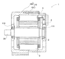
本発明に係る回転電機1は、図1に示すように、略有底筒状の一対のハウジング部材100、101とが開口部同士で接合されてなるハウジング10と、ハウジング10に軸受け110、111を介して回転自在に支承される回転軸20に固定された回転子2と、ハウジング10の内部で回転子2を包囲する位置でハウジング10に固定された固定子3と、を備えている。
(Embodiment)
As shown in FIG. 1, a rotating electrical machine 1 according to the present invention includes a
回転子2は、永久磁石により周方向に交互に異なる磁極を、固定子3の内周側と向き合う外周側に複数形成している。回転子2の磁極の数は、回転電機により異なるため限定されるものではない。本形態の回転電機では、8極(N極:4、S極:4)の回転子が用いられている。
The
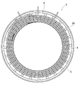
固定子3は、図2に示すように、固定子コア30と、複数の各相巻線から形成される三相の固定子巻線4と、固定子コア30と固定子巻線4との間に配された絶縁紙5と、を備えた構成を有している。
As shown in FIG. 2, the
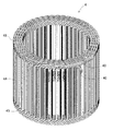
固定子コア30は、図3〜5に示すように、コア片部材31が積層された分割コア32を、分割コア32を構成するコア片部材31の一部分が重なるように周方向に複数個を配設してなる。固定子コア30は、内周面側に深さ方向が径方向と一致する複数のスロット33が形成された円環状を有している。
As shown in FIGS. 3 to 5, the
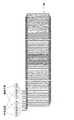
コア片部材31は、図5に示すように、ティース部35およびコアバック部34を形成するための形状となるように、厚さ0.3mmの電磁鋼板310をプレスで打ち抜いたものを、所定の枚数を同じ向きで積層してなる。
As shown in FIG. 5, the
分割コア32は、積層した鋼板からなるコア片部材31を、表面同士が対向した状態で積層したものである。なお、積層の仕方は、これに限定されるものでなく、コア片部材31の厚さにより適宜変更できる。例えば、表面同士−裏面同士−表表面同士−裏面同士・・・のように、表と裏を交互に積層した形態としてもよい。
The split
分割コア32は、図4に示すように、スロット33の底面とその底面に背向した固定子コア30の外周面の一部を区画するコアバック部34と、コアバック部34の底面の両端から径方向に突出して、その側面と底面との間でスロット33を区画する二本のティース部35と、を持つ。分割コア32を周方向に連結すると、隣接する二つの分割コア32は、それぞれの隣接するティース部35,35とで新たに一つのスロット33を区画する。
As shown in FIG. 4, the
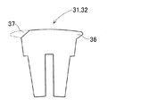
分割コア32は、コアバック部34の周方向の一方の端部に、端面34cから突出した重なり凸部36と、コアバック部34の周方向の他方の端部に、端面34dからくぼんだ重なり凹部37と、が形成されている。重なり凸部36は、隣接する分割コア32の重なり凹部37と重なり合うことが可能な形状に形成されている。本実施形態においては、略台形形状を有している。また、本実施形態において端面34c及び端面34dは、分割コア32の重なり凸部36及び重なり凹部37が形成されていない部分を示し、両端面34c,dは固定子コア30の軸方向に平行な断面上に位置するように形成されている。
The
なお、本実施形態では、コア片部材32の外周縁部の内、固定子巻線4に面する外周縁部全てをバリ取り処理している。このバリ取りにより、固定子巻線4の絶縁皮膜の損傷が抑制される。このバリ取りは、固定子巻線4と接して擦れる頻度の高いティース部35の先端部及びその周辺だけ処理してもよい。
In the present embodiment, the entire outer peripheral edge of the
分割コア32は、図6に示したように、固定子コア30を形成する分割コアの内、同一平面内に配設される分割コア32の数をn、重なり凸部36がコアバック部34の周方向の端面34cから突出した突出量をp、重なり凸部36の最も突出した部分の最内径部とスロット33の底面までの距離をq、スロット33の深さをt、としたときに下記数3式を満たしている。
![]()
![]()
固定子巻線4は、複数の巻線40を所定の巻回方法で巻回してなる。固定子巻線4を構成する巻線40は、図7(A)に示したように、銅製の導体41と、導体41の外周を覆い導体41を絶縁する内層420及び外層421からなる絶縁皮膜42とから形成されている。内層420および外層421を合わせた絶縁皮膜42の厚みは、100μm〜200μmの間に設定されている。
The stator winding 4 is formed by winding a plurality of
外層421はナイロン等の絶縁材、内層420は外層よりもガラス転移温度の高い熱可塑性樹脂またはポリアミドイミド等の絶縁材で形成されている。これにより、回転電機に発生する熱により外層421は内層420よりも早く軟化するので、同じスロット33に設置されている巻線40同士が外層421同士で熱接着する。その結果、同じスロット33に設置されている複数の巻線40が一体化し巻線40同士が剛体化するので、スロット33内の線巻線40の機械的強度が向上する。また、過剰な振動が発生しても、内層420と導体41の接着箇所よりも内層420と外層421との接着箇所が先に剥離するので、内層420と導体41との接着を維持し絶縁を確保できる。
The
さらに、固定子巻線4の巻線40は、図7(B)に示したように、内層420および外層421からなる絶縁皮膜42の外周をエポキシ樹脂等からなる融着材43で被覆してもよい。これにより、回転電機に発生する熱により融着材43は絶縁皮膜42よりも早く溶融するので、同じスロット33に設置されている複数の巻線40同士が融着材43同士により熱接着する。その結果、同じスロット33に設置されている複数の巻線40が一体化し巻線40同士が鋼体化することで、スロット33の巻線40の機械的強度が向上する。
Further, as shown in FIG. 7B, the winding 40 of the stator winding 4 is formed by covering the outer periphery of the insulating
固定子巻線4を構成する巻線40の絶縁皮膜42には、ポリフェニレンサルファイド(PPS)よりなる皮膜を用いても良い。
A coating made of polyphenylene sulfide (PPS) may be used for the insulating
固定子巻線4は、図8に示すように、それぞれ二本の三相巻線(U1,U2,V1,V2,W1,W2)により形成されている。 As shown in FIG. 8, the stator winding 4 is formed by two three-phase windings (U1, U2, V1, V2, W1, W2).
また、固定子巻線4は、図9に示すように、複数の巻線40を所定の形状に巻回してなる。固定子巻線4を構成する巻線40は、固定子コア30の内周側で周方向に沿って波巻きされた形状で成形されている。そして、固定子コア30に形成されたスロット33に収容される直線上のスロット収容部44と、隣り合ったスロット収容部44同士を接続するターン部45と、を備えている。スロット収容部44は、所定のスロット数(たとえば、3相×2個=6個)ごとのスロット33に収容され、ターン部45は、固定子コア30の軸方向の端面から突出して形成されている。
The stator winding 4 is formed by winding a plurality of
固定子巻線4は、複数の巻線40を一方の端部が固定子コア30の軸方向の端面から突出した状態で、周方向に沿って波状に巻装した状態で形成されている。固定子巻線4の1相は、周方向に沿って波状に巻装された2本の巻線40を他方の端部同士で接合した構成を有している。1相をなす2本の巻線40は、同一スロット33に収容される二つのスロット収容部44を有する。同一のスロット33に収容される二つのスロット収容部44は、周方向で隣り合ったスロット33の深さ方向での位置が交互に位置するように設置されている。そして、2本の巻線40は、2本の巻線40の巻装される方向が反転するスロット収容部44よりなる折り返し部46に接合部が形成された構成を有している。
The stator winding 4 is formed in a state in which a plurality of
固定子巻線4は、図10に展開図で示したように、互いに巻装方向が異なる二つの巻線部40a,40bをもつ成形体を各相(U1,U2,V1,V2,W1,W2)ごとに、6組用いて形成されている。二つの巻線部40a,40bのそれぞれは、中性点側の端部および相端子側の端部とは反対の端部側が、スロット収容部44(折り返し部46)を介して接続されている。各相の巻線40の結線方法は同様である。
As shown in a developed view in FIG. 10, the stator winding 4 is formed by forming a molded body having two winding portions 40a and 40b having different winding directions from each other (U1, U2, V1, V2, W1, For each W2), six sets are used. Each of the two winding portions 40a and 40b is connected to the end on the neutral point side and the end opposite to the end on the phase terminal side via the slot accommodating portion 44 (folded portion 46). . The method of connecting the
固定子巻線4は、図10に展開図を示した成形体を形成し、この成形体を折り返し部46が軸心側に位置するように所定の巻き数(たとえば、4回)に巻回して製造される。製造された固定子巻線4は、図9に示したように、各相の巻線40のスロット収容部44が径方向に並んだ状態で形成されている。このとき、径方向に並んだスロット収容部44は、固定子巻線4の周方向で小間隔を隔てた状態で位置している。
The stator winding 4 forms a molded body whose development is shown in FIG. 10, and the molded body is wound at a predetermined number of turns (for example, 4 times) so that the folded
次に、本実施形態の分割コア32の効果を、固定子3の形成方法を用いて説明する。
Next, the effect of the
本実施形態の回転電機1の固定子3の製造方法を以下に示す。
A method for manufacturing the
まず、巻線40を用いて固定子巻線4を形成(成形)する。また、所定の形状を有する分割コア32を形成する。
First, the stator winding 4 is formed (molded) using the winding 40. Further, the
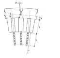
所定の数(n)の分割コア32を、固定子巻線4の外周の位置に周方向に沿って配列させる(図11(A))。
A predetermined number (n) of
そして、配列した分割コア32を縮径していき、固定子巻線4のスロット収容部44をスロット33に収容する。配列した分割コア32を縮径していくと、分割コア32の重なり凸部36が隣接する分割コア32と重なり始める(図11(B))。さらに、縮径させると、スロット収容部44がスロット33内に完全に収容され、分割コア32の重なり凸部36が隣接する分割コア32と完全に重なり合う(図11(C))。このとき、分割コア32のコアバック部34の端面34c,d同士が完全に密着する。これにより、固定子3が形成される。
Then, the arranged divided
つづいて、数3式で示される分割コア32の形状について説明する。
Next, the shape of the
固定子巻線4に挿入される分割コア32において、r:固定子巻線4の軸心からティース部44の先端部までの距離、w:分割コア32のコアバック部34の隣接する分割コア32と当接する最内径部での周方向の長さ、l:重なり凸部の最内径部(組み付け時に最初に重なり合う部分)でのコイルの周方向中心線を回転電機の軸心から放射状に伸ばした架空の線間の周方向の長さ、d:固定子巻線4の内径、としたときに(図12)、wは下記数4式で、lは下記数5式で表される。
![]()
![]()
![]()
![]()
このとき、端面34cからコイルの周方向中心線を回転電機の軸心から放射状に伸ばした架空の線までの長さeは、下記数6式で表される。

そして、分割コア32が固定子巻線4に完全に挿入されて固定子コア30を形成したときには、下記数7式の条件が成り立ち、数6式は、下記数8式となる。
![]()
![]()
![]()
![]()
そして、分割コア32が固定子巻線4に完全に挿入された状態では、重なり凸部36が隣接する分割コア32と重なり合うためには、下記数9式及び数9式を変形した数10式を満たす必要がある。
![]()
![]()
![]()
![]()
また、分割コア32が固定子巻線4に挿入される前の状態では、下記数11式及び数6式を変形した数12式が成り立つ。
![]()
![]()
![]()
![]()
分割コア32が固定子巻線4に挿入される前の状態では、重なり凸部36が隣接する分割コア32と重なり合っていないため、下記数13式及び数13式を変形した数14式を満たす必要がある。
![]()
![]()
![]()
![]()
上記の数10式及び数14式から、上記の数3式が得られる。
From the
本実施形態は、分割コア32が上記の数3式を満たすように形成されている。このため、分割コア32を固定子巻線4に挿入して固定子コア30を形成する工程中に、分割コア32が固定子巻線4に挿入される前には重なり凸部36が隣接する分割コア32と重なり合っておらず、固定子コア30を形成したときには重なり合う形態となっている。
In the present embodiment, the
さらに、本実施形態においては、分割コア32が固定子巻線4に挿入される前には重なり凸部36が隣接する分割コア32と重なり合っていないため、分割コア32のコアバック部34の最外径部の周方向の両端面を挟むようにして治具で保持して、挿入を行うことができた。これにより、分割コア32(のティース部35)が揺動しなくなり、挿入時に固定子巻線4が損傷を生じなくなった。
Further, in the present embodiment, since the overlapping
このように、本実施形態は、分割コア32の組み付け性に優れた回転電機1の固定子3となっている。
Thus, this embodiment is the
さらに、本実施形態は、分割コア32同士が重なる重なり部36,37の面積を数3式を満たす範囲で小さくすることが可能となる。すなわち、渦電流による損失を小さくすることができる。この結果、性能の優れた回転電機1を得ることができる。
Furthermore, in the present embodiment, it is possible to reduce the area of the overlapping
(変形形態)
本発明は、上記の実施形態のみに限定されるものではなく、図13〜16に示した分割コア32を用いても良い。
(Deformation)
The present invention is not limited to the above-described embodiment, and the
(第1変形形態)
本変形形態は、図13に示したように、コアバック部34の最内径部に重なり凸部36及び重なり凹部37が形成された形態の分割コア32を用いてなる例である。なお、図13においては、本変形形態の分割コア32の形状を、コア片部材31の形状で示した。
(First variation)
As shown in FIG. 13, the present modification is an example in which a
本変形形態においても、上記の数3式を満たす形状では、上記の実施形態と同様の効果を発揮する。
Also in this modified embodiment, the same shape as the above embodiment is exhibited in the shape satisfying the above-described
(第2変形形態)
本変形形態は、図14に示したように、コアバック部34の最外径部に重なり凸部36及び重なり凹部37が形成された形態の分割コア32を用いてなる例である。なお、図14においては、本変形形態の分割コア32の形状を、コア片部材31の形状で示した。
(Second variant)
As shown in FIG. 14, the present modified embodiment is an example in which a
本変形形態においても、上記の数3式を満たす形状では、上記の実施形態と同様の効果を発揮する。
Also in this modified embodiment, the same shape as the above embodiment is exhibited in the shape satisfying the above-described
(第3変形形態)
本変形形態は、図15に示したように、コアバック部34の外形部に外形が略山形の重なり凸部36及び重なり凹部37が形成された形態の分割コア32を用いてなる例である。なお、図15においては、本変形形態の分割コア32の形状を、コア片部材31の形状で示した。
(Third variant)
As shown in FIG. 15, this modified embodiment is an example in which a
本変形形態においても、上記の数3式を満たす形状では、上記の実施形態と同様の効果を発揮する。
Also in this modified embodiment, the same shape as the above embodiment is exhibited in the shape satisfying the above-described
(第4変形形態)
本変形形態は、図16に示したように、コアバック部34の周方向の両端部の全体に重なり凸部36及び重なり凹部37が形成された形態の分割コア32を用いてなる例である。なお、図16においては、本変形形態の分割コア32の形状を、コア片部材31の形状で示した。
(Fourth modification)
As shown in FIG. 16, the present modification is an example in which a
本変形形態においても、上記の数3式を満たす形状では、上記の実施形態と同様の効果を発揮する。
Also in this modified embodiment, the same shape as the above embodiment is exhibited in the shape satisfying the above-described
1:回転電機
2:回転子
3:固定子 30:固定子コア
31:コア片部材 32:分割コア
33:スロット 34:コアバック部
35:ティース部 36:重なり凸部
37:重なり凹部
4:固定子巻線
1: Rotating electric machine 2: Rotor 3: Stator 30: Stator core 31: Core piece member 32: Divided core 33: Slot 34: Core back part 35: Teeth part 36: Overlapping convex part 37: Overlapping concave part 4: Fixed Child winding
Claims (4)
該スロットに組み付けられた固定子巻線と、
を備えた回転電機の固定子であって、
該分割コアは、
該スロットの底面と該底面に背向した該固定子コアの外周面の一部を区画するコアバック部と、該コアバック部の該底面の両端から径方向に突出して、その側面と該底面との間で該スロットを区画する二本のティース部と、を持ち、
該コアバック部が、隣接する該分割コアと重なり合う重なり凸部と、隣接する該分割コアの該重なり凸部と勘合する重なり凹部を周方向の両端に有し、
該固定子コアを形成する該分割コアの内、同一平面内に配設される該分割コアの数をn、該重なり凸部が該コアバック部の周方向の端面から突出した突出量をp、該重なり凸部の最内径部と該スロットの底面までの距離をq、該スロット深さをt、としたときに数1式を満たすことを特徴とする回転電機の固定子。
A stator winding assembled to the slot;
A stator of a rotating electric machine with
The split core is
A bottom surface of the slot, a core back portion defining a part of the outer peripheral surface of the stator core facing away from the bottom surface, a side surface and the bottom surface projecting radially from both ends of the bottom surface of the core back portion Two teeth sections that divide the slot between
The core back portion has overlapping convex portions that overlap with the adjacent divided cores, and overlapping concave portions that engage with the overlapping convex portions of the adjacent divided cores at both ends in the circumferential direction,
Of the split cores forming the stator core, n is the number of split cores arranged in the same plane, and p is the amount of protrusion of the overlapping convex portion protruding from the circumferential end surface of the core back portion. A stator of a rotating electrical machine satisfying the equation (1) where q is the distance from the innermost diameter portion of the overlapping convex portion to the bottom surface of the slot, and t is the slot depth.
Priority Applications (2)
| Application Number | Priority Date | Filing Date | Title |
|---|---|---|---|
| JP2008172603A JP5151738B2 (en) | 2008-07-01 | 2008-07-01 | Rotating electric machine stator and rotating electric machine |
| US12/496,005 US7893590B2 (en) | 2008-07-01 | 2009-07-01 | Stator having high assembly |
Applications Claiming Priority (1)
| Application Number | Priority Date | Filing Date | Title |
|---|---|---|---|
| JP2008172603A JP5151738B2 (en) | 2008-07-01 | 2008-07-01 | Rotating electric machine stator and rotating electric machine |
Publications (2)
| Publication Number | Publication Date |
|---|---|
| JP2010016931A true JP2010016931A (en) | 2010-01-21 |
| JP5151738B2 JP5151738B2 (en) | 2013-02-27 |
Family
ID=41463822
Family Applications (1)
| Application Number | Title | Priority Date | Filing Date |
|---|---|---|---|
| JP2008172603A Active JP5151738B2 (en) | 2008-07-01 | 2008-07-01 | Rotating electric machine stator and rotating electric machine |
Country Status (2)
| Country | Link |
|---|---|
| US (1) | US7893590B2 (en) |
| JP (1) | JP5151738B2 (en) |
Cited By (1)
| Publication number | Priority date | Publication date | Assignee | Title |
|---|---|---|---|---|
| JP2013176283A (en) * | 2012-02-23 | 2013-09-05 | Samsung Electro-Mechanics Co Ltd | Multi-phase switched reluctance motor apparatus and control method thereof |
Families Citing this family (10)
| Publication number | Priority date | Publication date | Assignee | Title |
|---|---|---|---|---|
| JP5040988B2 (en) * | 2009-12-22 | 2012-10-03 | トヨタ自動車株式会社 | Stator and motor provided with the stator |
| JP5387698B2 (en) * | 2010-02-03 | 2014-01-15 | トヨタ自動車株式会社 | Stator core |
| JP5459110B2 (en) * | 2010-06-30 | 2014-04-02 | 株式会社デンソー | Rotating electric machine stator |
| JP5641902B2 (en) * | 2010-10-08 | 2014-12-17 | 日本発條株式会社 | Motor stator core and manufacturing method |
| EP2696476A4 (en) * | 2011-04-05 | 2016-03-02 | Toyota Motor Co Ltd | Stator and manufacturing method for stator |
| DE112017002057T5 (en) * | 2016-09-02 | 2018-12-27 | Nidec Corporation | Stator, stator manufacturing process and engine |
| DE102017200186A1 (en) | 2017-01-09 | 2018-07-12 | Siemens Aktiengesellschaft | Rotor plate for a permanent-magnet electric motor and rotor |
| CN111418131B (en) * | 2017-12-07 | 2022-06-14 | 京瓷工业工具株式会社 | Stator core |
| DK3745559T3 (en) * | 2019-05-27 | 2022-06-07 | Magnax Bv | Stator til aksialfluxmaskine |
| DE102021106186A1 (en) * | 2021-03-15 | 2022-09-15 | Ebm-Papst Mulfingen Gmbh & Co. Kg | Modular, segmented stator package |
Citations (2)
| Publication number | Priority date | Publication date | Assignee | Title |
|---|---|---|---|---|
| JP2002325383A (en) * | 2001-04-17 | 2002-11-08 | Moteurs Leroy-Somer | Rotary electronic machine having stator |
| JP2005341684A (en) * | 2004-05-26 | 2005-12-08 | Mitsubishi Electric Corp | Stacked core and its manufacturing method |
Family Cites Families (13)
| Publication number | Priority date | Publication date | Assignee | Title |
|---|---|---|---|---|
| US4166263A (en) * | 1977-10-03 | 1979-08-28 | Hitachi Metals, Ltd. | Magnetic core assembly for magnetizing columnar permanent magnet for use in electrostatic developing apparatus |
| JP3355700B2 (en) * | 1993-06-14 | 2002-12-09 | 松下電器産業株式会社 | Rotating electric machine stator |
| GB2310545B (en) * | 1996-02-22 | 2000-04-19 | Honda Motor Co Ltd | Stator core and method and apparatus for assembling same |
| JP3568364B2 (en) * | 1996-09-30 | 2004-09-22 | 松下電器産業株式会社 | Rotating machine core |
| JP3604326B2 (en) | 2000-05-29 | 2004-12-22 | 三菱電機株式会社 | Stator for rotating electric machine and method of manufacturing the same |
| US6700284B2 (en) * | 2001-03-26 | 2004-03-02 | Emerson Electric Co. | Fan assembly including a segmented stator switched reluctance fan motor |
| US7012350B2 (en) * | 2001-01-04 | 2006-03-14 | Emerson Electric Co. | Segmented stator switched reluctance machine |
| JP3786854B2 (en) * | 2001-08-30 | 2006-06-14 | 株式会社三井ハイテック | Manufacturing method of laminated iron core |
| US7111380B2 (en) * | 2002-10-31 | 2006-09-26 | Emerson Electric Co. | Method for forming an annular stator assembly |
| US7122933B2 (en) * | 2004-05-19 | 2006-10-17 | Emerson Electric Co. | Reduced coil segmented stator |
| US7348706B2 (en) * | 2005-10-31 | 2008-03-25 | A. O. Smith Corporation | Stator assembly for an electric machine and method of manufacturing the same |
| CN101523696B (en) * | 2006-10-13 | 2012-12-05 | 株式会社三井高科技 | Laminated iron core, and its manufacturing method |
| JP4623129B2 (en) * | 2008-04-21 | 2011-02-02 | 株式会社デンソー | Rotating electric machine stator and rotating electric machine |
-
2008
- 2008-07-01 JP JP2008172603A patent/JP5151738B2/en active Active
-
2009
- 2009-07-01 US US12/496,005 patent/US7893590B2/en active Active
Patent Citations (2)
| Publication number | Priority date | Publication date | Assignee | Title |
|---|---|---|---|---|
| JP2002325383A (en) * | 2001-04-17 | 2002-11-08 | Moteurs Leroy-Somer | Rotary electronic machine having stator |
| JP2005341684A (en) * | 2004-05-26 | 2005-12-08 | Mitsubishi Electric Corp | Stacked core and its manufacturing method |
Cited By (2)
| Publication number | Priority date | Publication date | Assignee | Title |
|---|---|---|---|---|
| JP2013176283A (en) * | 2012-02-23 | 2013-09-05 | Samsung Electro-Mechanics Co Ltd | Multi-phase switched reluctance motor apparatus and control method thereof |
| JP2014207858A (en) * | 2012-02-23 | 2014-10-30 | サムソン エレクトロ−メカニックス カンパニーリミテッド. | Method of controlling multi-phase switched reluctance motor apparatus |
Also Published As
| Publication number | Publication date |
|---|---|
| US7893590B2 (en) | 2011-02-22 |
| US20100001611A1 (en) | 2010-01-07 |
| JP5151738B2 (en) | 2013-02-27 |
Similar Documents
| Publication | Publication Date | Title |
|---|---|---|
| JP5151738B2 (en) | Rotating electric machine stator and rotating electric machine | |
| JP4445023B2 (en) | Rotating electric machine stator and rotating electric machine | |
| JP4396761B2 (en) | Rotating electric machine stator and rotating electric machine | |
| JP7344807B2 (en) | Coil bobbin, stator core of distributed winding radial gap type rotating electrical machine, and distributed winding radial gap type rotating electrical machine | |
| JP5314908B2 (en) | Rotating electric machine stator and rotating electric machine | |
| JP4623129B2 (en) | Rotating electric machine stator and rotating electric machine | |
| WO2017047247A1 (en) | Rotary electric machine | |
| JP2009131092A (en) | Stator of dynamo electric machine, and dynamo electric machine | |
| US8022592B2 (en) | Coil fixing member and rotary electric machine | |
| JP2010239691A (en) | Stator of rotary electric machine, and rotary electric machine | |
| JP4502041B2 (en) | Stator for rotating electric machine and method for manufacturing the same | |
| JP5515236B2 (en) | Rotating electric machine stator, rotating electric machine and stator coil forming method | |
| JP4535147B2 (en) | Rotating electric machine stator and rotating electric machine | |
| JP5309674B2 (en) | Stator coil manufacturing method | |
| JP5819037B2 (en) | Rotating electric machine stator and rotating electric machine | |
| JP5609937B2 (en) | Rotating electric machine stator | |
| JP2010259266A (en) | Stator of rotating electrical machine, and the rotating electrical machine | |
| JP2010011569A (en) | Stator | |
| JP2009213309A (en) | Stator of rotating electrical machine and the rotating electrical machine | |
| JP6319226B2 (en) | Rotating electrical machine stator | |
| JP2016046867A (en) | Rotary electric machine stator | |
| JP7044871B2 (en) | Rotating electric machine and manufacturing method of rotating electric machine | |
| JP6080964B2 (en) | Rotating electric machine stator | |
| JP6105835B2 (en) | Method for producing interphase insulating paper for rotating electrical machine | |
| JP2009213310A (en) | Stator of rotating electrical machine and the rotating electrical machine |
Legal Events
| Date | Code | Title | Description |
|---|---|---|---|
| A621 | Written request for application examination |
Free format text: JAPANESE INTERMEDIATE CODE: A621 Effective date: 20101208 |
|
| A977 | Report on retrieval |
Free format text: JAPANESE INTERMEDIATE CODE: A971007 Effective date: 20120731 |
|
| A131 | Notification of reasons for refusal |
Free format text: JAPANESE INTERMEDIATE CODE: A131 Effective date: 20120807 |
|
| A521 | Request for written amendment filed |
Free format text: JAPANESE INTERMEDIATE CODE: A523 Effective date: 20121001 |
|
| TRDD | Decision of grant or rejection written | ||
| A01 | Written decision to grant a patent or to grant a registration (utility model) |
Free format text: JAPANESE INTERMEDIATE CODE: A01 Effective date: 20121106 |
|
| A61 | First payment of annual fees (during grant procedure) |
Free format text: JAPANESE INTERMEDIATE CODE: A61 Effective date: 20121119 |
|
| FPAY | Renewal fee payment (event date is renewal date of database) |
Free format text: PAYMENT UNTIL: 20151214 Year of fee payment: 3 |
|
| R151 | Written notification of patent or utility model registration |
Ref document number: 5151738 Country of ref document: JP Free format text: JAPANESE INTERMEDIATE CODE: R151 |
|
| FPAY | Renewal fee payment (event date is renewal date of database) |
Free format text: PAYMENT UNTIL: 20151214 Year of fee payment: 3 |
|
| R250 | Receipt of annual fees |
Free format text: JAPANESE INTERMEDIATE CODE: R250 |
|
| R250 | Receipt of annual fees |
Free format text: JAPANESE INTERMEDIATE CODE: R250 |
|
| R250 | Receipt of annual fees |
Free format text: JAPANESE INTERMEDIATE CODE: R250 |
|
| R250 | Receipt of annual fees |
Free format text: JAPANESE INTERMEDIATE CODE: R250 |
|
| R250 | Receipt of annual fees |
Free format text: JAPANESE INTERMEDIATE CODE: R250 |
|
| R250 | Receipt of annual fees |
Free format text: JAPANESE INTERMEDIATE CODE: R250 |
|
| R250 | Receipt of annual fees |
Free format text: JAPANESE INTERMEDIATE CODE: R250 |
|
| R250 | Receipt of annual fees |
Free format text: JAPANESE INTERMEDIATE CODE: R250 |
|
| R250 | Receipt of annual fees |
Free format text: JAPANESE INTERMEDIATE CODE: R250 |