JP2010016846A - Base station device, mobile station device, and processing methods thereof - Google Patents
Base station device, mobile station device, and processing methods thereof Download PDFInfo
- Publication number
- JP2010016846A JP2010016846A JP2009191380A JP2009191380A JP2010016846A JP 2010016846 A JP2010016846 A JP 2010016846A JP 2009191380 A JP2009191380 A JP 2009191380A JP 2009191380 A JP2009191380 A JP 2009191380A JP 2010016846 A JP2010016846 A JP 2010016846A
- Authority
- JP
- Japan
- Prior art keywords
- station apparatus
- mobile station
- base station
- information
- unit
- Prior art date
- Legal status (The legal status is an assumption and is not a legal conclusion. Google has not performed a legal analysis and makes no representation as to the accuracy of the status listed.)
- Granted
Links
- 238000003672 processing method Methods 0.000 title claims description 10
- 238000013468 resource allocation Methods 0.000 claims abstract description 36
- 238000000034 method Methods 0.000 claims description 43
- 238000012545 processing Methods 0.000 claims description 16
- 238000010295 mobile communication Methods 0.000 claims description 9
- 238000004891 communication Methods 0.000 abstract description 23
- 230000005540 biological transmission Effects 0.000 description 65
- 238000005259 measurement Methods 0.000 description 31
- 230000004044 response Effects 0.000 description 28
- 238000013075 data extraction Methods 0.000 description 25
- 238000010586 diagram Methods 0.000 description 22
- 238000007726 management method Methods 0.000 description 20
- 125000004122 cyclic group Chemical group 0.000 description 18
- 238000001514 detection method Methods 0.000 description 16
- 230000001360 synchronised effect Effects 0.000 description 14
- 238000012937 correction Methods 0.000 description 10
- 230000008569 process Effects 0.000 description 10
- 238000013507 mapping Methods 0.000 description 8
- 230000006870 function Effects 0.000 description 6
- 239000000284 extract Substances 0.000 description 5
- 230000003044 adaptive effect Effects 0.000 description 4
- 238000006243 chemical reaction Methods 0.000 description 4
- 101000741965 Homo sapiens Inactive tyrosine-protein kinase PRAG1 Proteins 0.000 description 3
- 102100038659 Inactive tyrosine-protein kinase PRAG1 Human genes 0.000 description 3
- 230000008054 signal transmission Effects 0.000 description 3
- 238000001914 filtration Methods 0.000 description 2
- 230000007274 generation of a signal involved in cell-cell signaling Effects 0.000 description 2
- 238000003780 insertion Methods 0.000 description 2
- 230000037431 insertion Effects 0.000 description 2
- 238000012986 modification Methods 0.000 description 2
- 230000004048 modification Effects 0.000 description 2
- 230000008901 benefit Effects 0.000 description 1
- 230000001413 cellular effect Effects 0.000 description 1
- 238000013461 design Methods 0.000 description 1
- 230000002093 peripheral effect Effects 0.000 description 1
- 230000011664 signaling Effects 0.000 description 1
Images


Classifications
-
- H—ELECTRICITY
- H04—ELECTRIC COMMUNICATION TECHNIQUE
- H04W—WIRELESS COMMUNICATION NETWORKS
- H04W56/00—Synchronisation arrangements
- H04W56/0005—Synchronisation arrangements synchronizing of arrival of multiple uplinks
-
- H—ELECTRICITY
- H04—ELECTRIC COMMUNICATION TECHNIQUE
- H04W—WIRELESS COMMUNICATION NETWORKS
- H04W72/00—Local resource management
- H04W72/20—Control channels or signalling for resource management
- H04W72/23—Control channels or signalling for resource management in the downlink direction of a wireless link, i.e. towards a terminal
-
- H—ELECTRICITY
- H04—ELECTRIC COMMUNICATION TECHNIQUE
- H04L—TRANSMISSION OF DIGITAL INFORMATION, e.g. TELEGRAPHIC COMMUNICATION
- H04L5/00—Arrangements affording multiple use of the transmission path
- H04L5/003—Arrangements for allocating sub-channels of the transmission path
- H04L5/0053—Allocation of signaling, i.e. of overhead other than pilot signals
-
- H—ELECTRICITY
- H04—ELECTRIC COMMUNICATION TECHNIQUE
- H04W—WIRELESS COMMUNICATION NETWORKS
- H04W56/00—Synchronisation arrangements
- H04W56/001—Synchronization between nodes
-
- H—ELECTRICITY
- H04—ELECTRIC COMMUNICATION TECHNIQUE
- H04W—WIRELESS COMMUNICATION NETWORKS
- H04W56/00—Synchronisation arrangements
- H04W56/004—Synchronisation arrangements compensating for timing error of reception due to propagation delay
- H04W56/0045—Synchronisation arrangements compensating for timing error of reception due to propagation delay compensating for timing error by altering transmission time
-
- H—ELECTRICITY
- H04—ELECTRIC COMMUNICATION TECHNIQUE
- H04W—WIRELESS COMMUNICATION NETWORKS
- H04W56/00—Synchronisation arrangements
- H04W56/004—Synchronisation arrangements compensating for timing error of reception due to propagation delay
- H04W56/005—Synchronisation arrangements compensating for timing error of reception due to propagation delay compensating for timing error by adjustment in the receiver
-
- H—ELECTRICITY
- H04—ELECTRIC COMMUNICATION TECHNIQUE
- H04W—WIRELESS COMMUNICATION NETWORKS
- H04W56/00—Synchronisation arrangements
- H04W56/0055—Synchronisation arrangements determining timing error of reception due to propagation delay
-
- H—ELECTRICITY
- H04—ELECTRIC COMMUNICATION TECHNIQUE
- H04W—WIRELESS COMMUNICATION NETWORKS
- H04W72/00—Local resource management
- H04W72/20—Control channels or signalling for resource management
- H04W72/21—Control channels or signalling for resource management in the uplink direction of a wireless link, i.e. towards the network
-
- H—ELECTRICITY
- H04—ELECTRIC COMMUNICATION TECHNIQUE
- H04W—WIRELESS COMMUNICATION NETWORKS
- H04W74/00—Wireless channel access, e.g. scheduled or random access
- H04W74/08—Non-scheduled or contention based access, e.g. random access, ALOHA, CSMA [Carrier Sense Multiple Access]
-
- H—ELECTRICITY
- H04—ELECTRIC COMMUNICATION TECHNIQUE
- H04W—WIRELESS COMMUNICATION NETWORKS
- H04W92/00—Interfaces specially adapted for wireless communication networks
- H04W92/04—Interfaces between hierarchically different network devices
- H04W92/10—Interfaces between hierarchically different network devices between terminal device and access point, i.e. wireless air interface
Abstract
Description
本発明は、基地局装置、移動局装置およびそれらの処理方法、特に、移動局装置から基地局装置への上りリンクについて時間同期を行う基地局装置、移動局装置およびその処理方法に関する。 The present invention relates to a base station apparatus, a mobile station apparatus, and a processing method thereof, and more particularly, to a base station apparatus, a mobile station apparatus, and a processing method thereof that perform time synchronization on an uplink from the mobile station apparatus to the base station apparatus.
3GPP(3rd Generation Partnership Project)では、W−CDMA方式が第三世代セルラー移動通信方式として標準化され、順次サービスが開始されている。また、通信速度を更に上げたHSDPA(High Speed Downlink Packet Access:高速下りパケット接続)も標準化され、サービスが開始されようとしている。 In the 3rd Generation Partnership Project (3GPP), the W-CDMA system is standardized as a third generation cellular mobile communication system, and services are started sequentially. Also, HSDPA (High Speed Downlink Packet Access), which further increases the communication speed, has been standardized, and the service is about to start.
一方、3GPPでは、第三世代無線アクセスの進化(Evolved Universal Terrestrial Radio Access;以下、「EUTRA」という)が検討されている。EUTRAの下りリンクとして、OFDM(Orthogonal Frequency Division Multiplexing;直交周波数分割多重)方式が提案されている。また、EUTRAの上りリンクとして、DFT(Discrete Fourier Transform;離散フーリエ変換)−spread OFDM方式のシングルキャリア通信方式が提案されている。 On the other hand, in 3GPP, the evolution of third generation radio access (Evolved Universal Terrestrial Radio Access; hereinafter referred to as “EUTRA”) is being studied. An OFDM (Orthogonal Frequency Division Multiplexing) system has been proposed as a downlink of EUTRA. In addition, a single carrier communication scheme of DFT (Discrete Fourier Transform) -spread OFDM scheme has been proposed as an uplink of EUTRA.
図15は、EUTRAの上りリンクおよび下りリンクのチャネル構成を示す図である。
EUTRAの下りリンクは、下りリンクパイロットチャネルDPiCH(Downlink Pilot Channel)、下りリンク同期チャネルDSCH(Downlink Synchronization Channel)、下りリンク共通制御チャネル、下りリンク共用制御チャネルPDCCH(Physical Downlink Control Channel)(L1/L2(Layer1/Layer2)制御チャネル)、下りリンク共用データチャネルDL−SCH(Downlink-Shared Channel)により構成されている。
また、EUTRAの上りリンクは、上りリンクパイロットチャネルUPiCH(Uplink Pilot Channel)、ランダムアクセスチャネルRACH(Random Access Channel)、上りリンク共用データチャネルUL−SCH(Uplink-Shared Channel)、上りリンク共用制御チャネルPUCCH(Physical Uplink Control Channel)により構成されている(非特許文献1を参照)。
FIG. 15 is a diagram illustrating the uplink and downlink channel configurations of EUTRA.
The downlink of EUTRA includes a downlink pilot channel DPiCH (Downlink Pilot Channel), a downlink synchronization channel DSCH (Downlink Synchronization Channel), a downlink common control channel, a downlink shared control channel PDCCH (Physical Downlink Control Channel) (L1 / L2 (Layer1 / Layer2) control channel), a downlink shared data channel DL-SCH (Downlink-Shared Channel).
Further, the uplink of EUTRA includes an uplink pilot channel UPiCH (Uplink Pilot Channel), a random access channel RACH (Random Access Channel), an uplink shared data channel UL-SCH (Uplink-Shared Channel), and an uplink shared control channel PUCCH. (Physical Uplink Control Channel) (see Non-Patent Document 1).
図16は、ランダムアクセスチャネルRACHと、上りリンク共用データチャネルUL−SCHとの無線リソース上への配置例を示した図である。図16に示す図は、横軸に時間をとり、縦軸に周波数をとっている。図16は、1つの無線フレームの構成を示しており、この無線フレームは複数の無線リソースに分割される。この例では、無線リソースは、周波数方向に1.25MHz、時間方向に1msの領域を単位として構成され、これらの領域に、図15にて説明したランダムアクセスチャネルRACHと、上りリンク共用データチャネルUL−SCHとが図示のように割当てられている。このように、ランダムアクセスチャネルRACHの最小単位は、1.25MHzの帯域を使用する。なお、図16において、上りリンクパイロットチャネルUPiCHは、上りリンク共用データチャネルUL−SCHの領域内に、シンボル単位、サブキャリア単位で分散して配置される。また、EUTRAでは、ランダムアクセスチャネルRACH用に、複数のチャネルを用意しているので、同時に複数のランダムアクセスに対応できる。ランダムアクセスチャネルRACHの使用目的のうちの最大のものは、移動局装置−基地局装置間を同期させることである。また、ランダムアクセスチャネルRACHでは、無線リソースを割当てるスケジューリングのリクエストなどの数ビットの情報も送信して、接続時間を短くすることも考慮されている(非特許文献2を参照)。 FIG. 16 is a diagram illustrating an arrangement example of the random access channel RACH and the uplink shared data channel UL-SCH on radio resources. In the diagram shown in FIG. 16, the horizontal axis represents time, and the vertical axis represents frequency. FIG. 16 shows the configuration of one radio frame, and this radio frame is divided into a plurality of radio resources. In this example, the radio resources are configured in units of 1.25 MHz in the frequency direction and 1 ms in the time direction, and the random access channel RACH described in FIG. 15 and the uplink shared data channel UL are included in these regions. -SCH is assigned as shown. Thus, the minimum unit of the random access channel RACH uses a band of 1.25 MHz. In FIG. 16, uplink pilot channel UPiCH is distributed and arranged in units of symbols and subcarriers in the region of uplink shared data channel UL-SCH. In addition, since EUTRA provides a plurality of channels for the random access channel RACH, it can cope with a plurality of random accesses at the same time. The largest use purpose of the random access channel RACH is to synchronize between the mobile station apparatus and the base station apparatus. In addition, in the random access channel RACH, it is also considered to shorten the connection time by transmitting several bits of information such as a scheduling request for allocating radio resources (see Non-Patent Document 2).
ランダムアクセスチャネルRACHでは、同期をとるためにプリアンブルのみを送信する。プリアンブルには、情報を表す信号パターンであるシグネチャが含まれている。数十種類のシグネチャを用意しておき、これらの中から選択して用いることで、数ビットの情報を表現することができる。現在、EUTRAでは、シグネチャにより6ビットの情報を送信する。この6ビットのために、2の6乗の64種類のシグネチャが用意される。
シグネチャによる6ビットのうち、5ビットにランダムIDを割当て、残りの1ビットにランダムアクセスの理由、下りリンクのパスロス/CQI(Channel Quality Indicator)などのいずれかの情報を割当てる(非特許文献3を参照)。
In the random access channel RACH, only the preamble is transmitted for synchronization. The preamble includes a signature that is a signal pattern representing information. By preparing dozens of types of signatures and selecting and using them, several bits of information can be expressed. Currently, EUTRA transmits 6-bit information by signature. For these 6 bits, 64 signatures of 2 6 are prepared.
Random ID is assigned to 5 bits out of 6 bits by the signature, and any information such as the reason for random access, downlink path loss / CQI (Channel Quality Indicator) is assigned to the remaining 1 bit (Non-patent Document 3) reference).
図17は、ランダムアクセスチャネルRACHを用いた上りリンク同期のシーケンス例を示すシーケンス図である。まず、移動局装置が、ランダムID、ランダムアクセスの理由、下りリンクのパスロス/CQI情報などに基づき、シグネチャを選択し、ランダムアクセスチャネルRACHで、該シグネチャを含むプリアンブルを送信する(メッセージMa1)。基地局装置は、移動局装置からのプリアンブルを受信すると、予めプリアンブルとして記憶している信号パターンとこの受信したプリアンブルを比較することで、移動局装置−基地局装置間の同期タイミングずれを算出し、L2/L3(Layer2/Layer3)メッセージを送信するためスケジューリングを行い、プリアンブルに含まれるランダムアクセス理由からセル内移動局識別情報C−RNTI(Cell Radio Network Temporary Identifier)が必要な移動局装置にはC−RNTIを割当て、同期タイミングずれ情報、スケジューリング情報、C−RNTIおよびランダムIDを含んだプリアンブル応答を送信する(メッセージMa2)。移動局装置は、送信したランダムIDが含まれる基地局装置からのプリアンブル応答を抽出して、スケジューリングされた無線リソースでL2/L3メッセージを送信する(メッセージMa3)。基地局装置は、移動局装置からのL2/L3メッセージを受信して、移動局装置間で衝突が起こっているかどうか判断するためのコンテンションレゾリューションを移動局装置に送信する(メッセージMa4)(非特許文献3を参照)。 FIG. 17 is a sequence diagram showing a sequence example of uplink synchronization using the random access channel RACH. First, the mobile station apparatus selects a signature based on a random ID, a reason for random access, downlink path loss / CQI information, and the like, and transmits a preamble including the signature on the random access channel RACH (message Ma1). When the base station apparatus receives the preamble from the mobile station apparatus, the base station apparatus compares the received preamble with the signal pattern stored in advance as a preamble, thereby calculating a synchronization timing shift between the mobile station apparatus and the base station apparatus. Mobile station apparatus that performs scheduling to transmit L2 / L3 (Layer2 / Layer3) message and requires in-cell mobile station identification information C-RNTI (Cell Radio Network Temporary Identifier) for the reason of random access included in the preamble C-RNTI is allocated, and a preamble response including synchronization timing deviation information, scheduling information, C-RNTI and random ID is transmitted (message Ma2). The mobile station apparatus extracts a preamble response from the base station apparatus including the transmitted random ID, and transmits an L2 / L3 message using the scheduled radio resource (message Ma3). The base station apparatus receives the L2 / L3 message from the mobile station apparatus, and transmits a contention resolution for determining whether or not a collision occurs between the mobile station apparatuses to the mobile station apparatus (message Ma4). (See Non-Patent Document 3).
ランダムアクセスでは、複数の移動局装置が、シグネチャおよびランダムアクセスチャネルRACHとして同じものを選択した場合に、これらの移動局装置のランダムアクセスは衝突してしまう。ランダムアクセスが衝突したときのシーケンスを、図17を参照して説明する。複数の移動局装置が、同じシグネチャを選択し、同じ時間・周波数を有する無線リソースブロック、すなわち同じランダムアクセスチャネルRACHを用いてプリアンブルを送信した場合、メッセージMa1で衝突が発生する。この衝突により、基地局装置がメッセージMa1を検出できない場合、基地局装置は、プリアンブル応答(メッセージMa2)を返すことができない。移動局装置は、基地局装置からのプリアンブル応答(メッセージMa2)を受信できないので、一定期間の後、再度、シグネチャ、ランダムアクセスチャネルRACHを選択し、ランダムアクセスを行う。また、衝突が起きていても、基地局装置が、プリアンブル(メッセージMa1)を検出できた場合、基地局装置は、L2/L3メッセージスケジューリングと同期タイミングずれを算出し、移動局装置にプリアンブル応答(メッセージMa2)を返す。しかし、このプリアンブル応答については、複数の移動局装置が受信することになり、複数の移動局装置が、スケジューリングされたリソースにL2/L3メッセージ(メッセージMa3)の送信を行うので、メッセージMa3で衝突が発生する。基地局装置は、この衝突によりL2/L3メッセージを受信できず、応答を返せない。L2/L3メッセージの応答がないので、移動局装置は、再度、シグネチャを選択し、ランダムアクセスを行う。 In random access, when a plurality of mobile station apparatuses select the same signature and random access channel RACH, the random access of these mobile station apparatuses collides. A sequence when random access collides will be described with reference to FIG. When a plurality of mobile station apparatuses select the same signature and transmit a preamble using radio resource blocks having the same time and frequency, that is, the same random access channel RACH, a collision occurs in the message Ma1. If the base station apparatus cannot detect the message Ma1 due to this collision, the base station apparatus cannot return a preamble response (message Ma2). Since the mobile station apparatus cannot receive the preamble response (message Ma2) from the base station apparatus, the mobile station apparatus selects the signature and the random access channel RACH again after a certain period and performs random access. If the base station apparatus can detect the preamble (message Ma1) even if a collision occurs, the base station apparatus calculates the L2 / L3 message scheduling and the synchronization timing shift, and sends a preamble response ( Message Ma2) is returned. However, the preamble response is received by a plurality of mobile station apparatuses, and the plurality of mobile station apparatuses transmit an L2 / L3 message (message Ma3) to the scheduled resource. Will occur. The base station apparatus cannot receive the L2 / L3 message due to the collision and cannot return a response. Since there is no response to the L2 / L3 message, the mobile station device selects a signature again and performs random access.
移動局装置と基地局装置との間の上りリンク同期が外れた状態(例えば、長い期間データの送受信がなく、移動局装置が長い周期で下りリンクリソース割当ての信号を監視しているDRX(Discontinuous Reception)状態)の場合、基地局装置からの下りリンクのデータ送信が再開されると、移動局装置は、ハイブリッド自動再送HARQ(Hybrid Automatic Repeat Request)のための受信応答であるACK/NACK(Acknowledgement / Negative Acknowledgement)を送信することができない。なぜなら、上りリンク同期が外れているので、ハイブリッド自動再送HARQのACK/NACKを送信すると、他の移動局装置に対して干渉してしまうためである。よって、下りリンクのデータ送信再開の際に、ランダムアクセスを用いた上りリンク同期をとる必要がある。しかし、このランダムアクセスを行う際に衝突が発生してしまったときに、下りリンクのデータ送信が再開されるまでに長い時間がかかることが懸念されている。これを回避するために、下りリンクのデータ送信再開用のシグネチャを用いるなどして、下りリンクのデータ送信再開時のランダムアクセスにおいて、衝突を発生させないような提案が行われている。 A state in which uplink synchronization between the mobile station device and the base station device is out of sync (for example, DRX (Discontinuous In the case of (Reception) state), when downlink data transmission from the base station apparatus is resumed, the mobile station apparatus receives an ACK / NACK (Acknowledgement) that is a reception response for Hybrid Automatic Repeat Request (HARQ). / Negative Acknowledgment) cannot be sent. This is because uplink synchronization is lost, and therefore, if an ACK / NACK of hybrid automatic retransmission HARQ is transmitted, it interferes with other mobile station apparatuses. Therefore, it is necessary to perform uplink synchronization using random access when downlink data transmission is resumed. However, when a collision occurs during this random access, there is a concern that it will take a long time to resume downlink data transmission. In order to avoid this, a proposal has been made to prevent collision in random access when downlink data transmission is resumed by using a signature for resuming downlink data transmission.
図18は、下りリンクのデータ送信再開のランダムアクセスにおいて、衝突を発生させないようにしたシーケンスを示す図である。
基地局装置は、上りリンク同期が外れた状態の移動局装置への下りリンクのデータ送信再開を決定すると、その移動局装置に対して、上りリンク同期要求を送信する(メッセージMb1)。この上りリンク同期要求は、L1/L2(Layer1/Layer2)制御チャネルを使って送信される。上りリンク同期要求の中には、移動局装置が送信するべきランダムアクセスのシグネチャID番号が含まれている。これを専用シグネチャと呼ぶ。移動局装置は、上りリンク同期要求で受信した専用シグネチャを使って、ランダムアクセスを行う、すなわちプリアンブルを送信する(メッセージMb2)。専用シグネチャを含んだプリアンブルを受信した基地局装置は、このプリアンブルにより同期タイミングのずれを検出する。そして、基地局装置は、移動局装置に対して、同期タイミングのずれ示すTA(Timing Advance)コマンドをプリアンブル応答として送信する(メッセージMb3)。基地局装置は、TAコマンドを送信すると、下りリンクリソース割当てを含むL1/L2制御チャネルを送り(メッセージMb4)、続いて、下りリンクのデータ送信を再開する(メッセージMb5)(非特許文献4を参照)。
FIG. 18 is a diagram illustrating a sequence in which no collision occurs in random access for resuming downlink data transmission.
When the base station apparatus determines to resume downlink data transmission to the mobile station apparatus in a state in which uplink synchronization is lost, the base station apparatus transmits an uplink synchronization request to the mobile station apparatus (message Mb1). This uplink synchronization request is transmitted using an L1 / L2 (Layer1 / Layer2) control channel. The uplink synchronization request includes a signature ID number for random access to be transmitted by the mobile station apparatus. This is called a dedicated signature. The mobile station apparatus performs random access, that is, transmits a preamble (message Mb2) using the dedicated signature received in the uplink synchronization request. The base station apparatus that has received the preamble including the dedicated signature detects a synchronization timing shift based on the preamble. Then, the base station device transmits a TA (Timing Advance) command indicating a synchronization timing shift as a preamble response to the mobile station device (message Mb3). When the base station apparatus transmits the TA command, the base station apparatus sends an L1 / L2 control channel including downlink resource allocation (message Mb4), and then resumes downlink data transmission (message Mb5) (Non-Patent Document 4). reference).
上述のランダムアクセスにおいて衝突を発生させないようにした下りリンクのデータ送信再開方法では、ハイブリッド自動再送HARQのACK/NACKが不要な下りリンク共用制御チャネルPDCCH(L1/L2制御チャネル)を使って、上りリンク同期要求を送信する。下りリンク共用制御チャネルPDCCHは、基地局装置と移動局装置との間でユーザーデータなどを送受信するための適応変調のパラメータやチャネルの割当て情報などを伝送するチャネルであるため、無線リソースに固定的に割当てられて頻繁に伝送されるチャネルである。
解決しようとする問題点は、このように頻繁に伝送される下りリンク共用制御チャネルPDCCHに、稀にしか発生しない上りリンク同期要求を配置する領域を確保すると、無線リソースの利用効率が悪くなるという点である。
In the downlink data transmission restart method in which collision does not occur in the random access described above, the downlink shared control channel PDCCH (L1 / L2 control channel) that does not require hybrid automatic retransmission HARQ ACK / NACK is used to Send a link synchronization request. The downlink shared control channel PDCCH is a channel that transmits adaptive modulation parameters, channel allocation information, and the like for transmitting and receiving user data between the base station apparatus and the mobile station apparatus. It is a channel that is assigned to and frequently transmitted.
The problem to be solved is that, if an area for arranging an uplink synchronization request that rarely occurs is secured in the downlink shared control channel PDCCH that is frequently transmitted in this way, the utilization efficiency of radio resources is deteriorated. Is a point.
(1)この発明は上述した課題を解決するためになされたもので、本発明の移動局装置は、移動通信システムにおける移動局装置であって、無線リソースの割当て情報が配置される領域を含む下りリンク制御チャネルを基地局装置から受信する手段と、ランダムアクセス指示を表す情報を前記下りリンク制御チャネルの所定の領域から検出し、前記下りリンク制御チャネルから専用シグネチャの識別番号を検出したとき、前記識別番号で指定されたランダムアクセス用のプリアンブルを前記基地局装置に送信する手段とを備え、前記所定の領域は前記無線リソースの割当て情報が配置される領域を含むことを特徴とする。 (1) The present invention has been made to solve the above-described problem, and the mobile station apparatus of the present invention is a mobile station apparatus in a mobile communication system, and includes an area where radio resource allocation information is arranged. Means for receiving a downlink control channel from the base station apparatus, and detecting information indicating a random access instruction from a predetermined area of the downlink control channel, and when detecting an identification number of a dedicated signature from the downlink control channel, Means for transmitting a preamble for random access designated by the identification number to the base station apparatus, wherein the predetermined area includes an area in which the allocation information of the radio resource is arranged.
(2)また、本発明の基地局装置は、移動通信システムにおける基地局装置であって、無線リソースの割当て情報が配置される領域を含む下りリンク制御チャネルを移動局装置へ送信する手段と、前記移動局装置からのランダムアクセス用のプリアンブルを検出する手段とを備え、前記移動局装置へランダムアクセスを指示するとき、前記送信する手段は、ランダムアクセス指示を表す情報を前記下りリンク制御チャネルの所定の領域に含め、前記下りリンク制御チャネルに専用シグネチャの識別番号を含めて前記移動局装置に送信し、前記検出する手段は前記移動局装置から送信される前記識別番号で指定された前記ランダムアクセス用のプリアンブルを検出し、前記所定の領域は前記無線リソースの割当て情報が配置される領域を含むことを特徴とする。 (2) Moreover, the base station apparatus of the present invention is a base station apparatus in a mobile communication system, and transmits a downlink control channel including a region where radio resource allocation information is arranged to the mobile station apparatus; Means for detecting a preamble for random access from the mobile station apparatus, and when instructing the mobile station apparatus to perform random access, the means for transmitting transmits information indicating the random access instruction in the downlink control channel. In the predetermined area, the downlink control channel includes an identification number of a dedicated signature and transmits it to the mobile station apparatus, and the means for detecting the random number specified by the identification number transmitted from the mobile station apparatus An access preamble is detected, and the predetermined area includes an area where the radio resource allocation information is arranged. The features.
(3)また、本発明の移動局装置の処理方法は、移動通信システムにおける移動局装置の処理方法であって、前記移動局装置が、無線リソースの割当て情報が配置される領域を含む下りリンク制御チャネルを基地局装置から受信するステップと、前記移動局装置が、ランダムアクセス指示を表す情報を前記下りリンク制御チャネルの所定の領域から検出し、前記下りリンク制御チャネルから専用シグネチャの識別番号を検出したとき、前記識別番号で指定されたランダムアクセス用のプリアンブルを前記基地局装置に送信するステップを備え、前記所定の領域は前記無線リソースの割当て情報が配置される領域を含むことを特徴とする。 (3) A mobile station apparatus processing method according to the present invention is a mobile station apparatus processing method in a mobile communication system, wherein the mobile station apparatus includes an area where radio resource allocation information is arranged. Receiving the control channel from the base station apparatus, and the mobile station apparatus detects information indicating a random access instruction from a predetermined region of the downlink control channel, and determines an identification number of a dedicated signature from the downlink control channel. A step of transmitting, when detected, a random access preamble designated by the identification number to the base station apparatus, wherein the predetermined area includes an area in which the radio resource allocation information is arranged; To do.
(4)また、本発明の基地局装置の処理方法は、移動通信システムにおける基地局装置の処理方法であって、前記基地局装置が、無線リソースの割当て情報が配置される領域を含む下りリンク制御チャネルを移動局装置へ送信するステップと、前記基地局装置が、前記移動局装置からのランダムアクセス用のプリアンブルを検出するステップを備え、前記移動局装置へランダムアクセスを指示するとき、前記送信するステップにて、前記基地局装置が、ランダムアクセス指示を表す情報を前記下りリンク制御チャネルの所定の領域に含め、前記下りリンク制御チャネルに専用シグネチャの識別番号を含めて前記移動局装置に送信し、前記検出するステップにて、前記基地局装置が、前記移動局装置から送信される前記識別番号で指定された前記ランダムアクセス用のプリアンブルを検出し、前記所定の領域は前記無線リソースの割当て情報が配置される領域を含むことを特徴とする。 (4) A base station apparatus processing method according to the present invention is a base station apparatus processing method in a mobile communication system, wherein the base station apparatus includes a region where radio resource allocation information is arranged. Transmitting the control channel to the mobile station apparatus, and the base station apparatus detecting a random access preamble from the mobile station apparatus, wherein the transmission is performed when instructing the mobile station apparatus to perform random access. In this step, the base station apparatus includes information indicating a random access instruction in a predetermined area of the downlink control channel, and includes an identification number of a dedicated signature in the downlink control channel and transmits the information to the mobile station apparatus. In the detecting step, the base station apparatus is designated before the identification number transmitted from the mobile station apparatus. Detecting a preamble for random access, wherein the predetermined area is characterized by including a region allocation information of the radio resources are arranged.
本発明の基地局装置は、基地局装置と移動局装置との同期通信に用いるパラメータを配置する無線フレーム上の領域に、移動局装置に対する上りリンク同期要求を表す情報を配置するので、優れた無線リソースの利用効率が得られるように、上りリンク同期要求を配置することができるという利点がある。 Since the base station apparatus of the present invention arranges information representing an uplink synchronization request for a mobile station apparatus in an area on a radio frame in which parameters used for synchronous communication between the base station apparatus and the mobile station apparatus are arranged, the base station apparatus is excellent There is an advantage that an uplink synchronization request can be arranged so that utilization efficiency of radio resources can be obtained.
以下、図面を参照して、本発明の実施の形態について説明する。本実施形態における無線通信システムは、第三世代無線アクセスの進化EUTRAと同様に、基地局装置と複数の移動局装置とからなる。本実施形態において、移動局装置から基地局装置への通信接続を「上りリンク」といい、基地局装置から移動局装置への通信接続を「下りリンク」という。本実施形態における下りリンクは、下りリンクパイロットチャネルDPiCH、下りリンク同期チャネルDSCH、下りリンク共通制御チャネル、下りリンク共用制御チャネルPDCCH(L1/L2(Layer1/Layer2)制御チャネル)、下りリンク共用データチャネルDL−SCHにより構成されている。また、本実施形態における上りリンクは、上りリンクパイロットチャネルUPiCH、ランダムアクセスチャネルRACH、上りリンク共用データチャネルUL−SCHにより構成されている。 Embodiments of the present invention will be described below with reference to the drawings. The radio communication system according to the present embodiment includes a base station apparatus and a plurality of mobile station apparatuses, as in the case of evolution EUTRA of third generation radio access. In this embodiment, the communication connection from the mobile station apparatus to the base station apparatus is referred to as “uplink”, and the communication connection from the base station apparatus to the mobile station apparatus is referred to as “downlink”. The downlink in this embodiment is a downlink pilot channel DPiCH, a downlink synchronization channel DSCH, a downlink common control channel, a downlink shared control channel PDCCH (L1 / L2 (Layer1 / Layer2) control channel), a downlink shared data channel. It is comprised by DL-SCH. Further, the uplink in the present embodiment is configured by an uplink pilot channel UPiCH, a random access channel RACH, and an uplink shared data channel UL-SCH.
ランダムアクセスチャネルRACHとは、ガードタイムを持つ上りリンクのチャネルである。このため、上りリンクについて基地局装置との時間の同期が取れていない移動局装置が、このランダムアクセスチャネルRACHを用いて送信しても、該移動局装置の同期ずれがこのガードタイムの範囲内であれば、他のチャネルに対して干渉を起こすことなく送信することができる。このランダムアクセスチャネルRACHにて送信するプリアンブルに含めるシグネチャは、64個のシグネチャから選択可能である。移動局装置は、これら64個のシグネチャの中から一つを選択し、プリアンブルに含めて送信する。 The random access channel RACH is an uplink channel having a guard time. For this reason, even if a mobile station apparatus that is not synchronized in time with the base station apparatus for the uplink transmits using the random access channel RACH, the synchronization deviation of the mobile station apparatus is within the guard time range. Then, transmission can be performed without causing interference to other channels. Signatures to be included in the preamble transmitted on the random access channel RACH can be selected from 64 signatures. The mobile station apparatus selects one of these 64 signatures and transmits it by including it in the preamble.
下りリンク共用制御チャネルPDCCH(L1/L2制御チャネル)は、各無線フレームに固定した領域が割当てられており、その領域は、下りリンク制御用と上りリンク制御用に分けられる。この下りリンク制御用の領域と、上りリンク制御用の領域とには、移動局装置毎の下りリンク制御用の情報と、上りリンク制御用の情報とが各々配置される。
基地局装置が送信したこれらの制御用の情報の中から、移動局装置は、自装置を対象とした情報を受信する。これらの制御用の情報には、各移動局装置に対するリソース(周波数と時間とで決まる無線フレーム上の領域)割当ての情報、適応変調のパラメータ、ハイブリッド自動再送HARQなど、基地局装置と移動局装置とのデータ通信(同期通信)に用いるパラメータが含まれている。
The downlink shared control channel PDCCH (L1 / L2 control channel) is assigned a fixed area to each radio frame, and the area is divided into downlink control and uplink control. In the downlink control area and the uplink control area, downlink control information and uplink control information for each mobile station apparatus are arranged.
From these control information transmitted by the base station apparatus, the mobile station apparatus receives information intended for itself. The control information includes base station apparatus and mobile station apparatus such as resource allocation information (region on radio frame determined by frequency and time) allocation to each mobile station apparatus, adaptive modulation parameters, and hybrid automatic retransmission HARQ. Parameters used for data communication (synchronous communication).
図1は、上りリンクの同期が取れている移動局装置に対する下りリンク制御用の情報のフォーマットを示す図である。この下りリンク制御用の情報は、図1に示すように、下りリンクリソース割当て(12ビット:下りリンクについて移動局装置に割当てられたリソース位置を示す)、MCS(Modulation and Coding Scheme;変調及び符号化方式)情報(3ビット:変調方式、符号化方式を指定する)、MIMO(Multiple Input Multiple Output)情報(2ビット:アンテナ本数などを指定する)、ペイロードサイズ(5ビット:下りリンクで割当てられたリソース内に含まれるペイロードのサイズ)、HARQ情報(5ビット)、C−RNTI(Cell specific Radio Network Temporary Identity:セル内移動局識別情報)(16ビット:基地局装置内において移動局装置を識別するための移動局装置識別情報)で構成されている。この下りリンク制御用の情報の巡回冗長検査CRC(Cyclic Redundancy Check)は、C−RNTIと兼用されている。すなわち、該領域を含んだ下りリンク制御用の情報について、巡回冗長検査CRCを算出すると、その値がC−RNTIとなる。移動局装置は、各下りリンク制御用の情報について、巡回冗長検査CRCを算出し、その結果が自装置のC−RNTIであるか否かに基づき、該下りリンク制御用の情報が自装置に対する情報であるか否かを判定する。 FIG. 1 is a diagram illustrating a format of information for downlink control for a mobile station apparatus in which uplink synchronization is established. As shown in FIG. 1, the downlink control information includes downlink resource allocation (12 bits: indicates a resource position allocated to the mobile station apparatus for the downlink), MCS (Modulation and Coding Scheme) Information) (3 bits: specify the modulation method and encoding method), MIMO (Multiple Input Multiple Output) information (2 bits: specify the number of antennas, etc.), payload size (5 bits: assigned in the downlink) Payload size included in the resource), HARQ information (5 bits), C-RNTI (Cell specific Radio Network Temporary Identity) (16 bits: identifies the mobile station device in the base station device) Mobile station apparatus identification information). This cyclic redundancy check CRC (Cyclic Redundancy Check) of information for downlink control is also used as C-RNTI. That is, when the cyclic redundancy check CRC is calculated for the downlink control information including the area, the value becomes C-RNTI. The mobile station apparatus calculates a cyclic redundancy check CRC for each downlink control information, and based on whether the result is the C-RNTI of the own apparatus, the downlink control information is transmitted to the own apparatus. It is determined whether it is information.
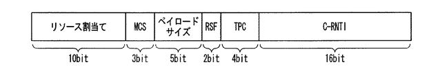
図2は、上りリンクの同期が取れている移動局装置に対する上りリンク制御用の情報のフォーマットを示す図である。上りリンク制御用の情報は、図2に示すように、上りリンクリソース割当て(10ビット:上りリンクについて移動局装置に割当てられたリソース位置を示す)、MCS情報(3ビット:変調方式、符号化方式を指定する)、ペイロードサイズ(5ビット:下りリンクで割当てられたリソース内に含まれるペイロードのサイズ)、RSF(Reference Signal Format)(2ビット:リファレンス信号送信フォーマット)、TPC(Transmission Power Control:送信電力制御)(4ビット:送信電力)、C−RNTIで構成されている。この上りリンク制御用の情報の巡回冗長検査CRCは、C−RNTIと兼用されている。すなわち、図1の下りリンク制御用の情報のときと同様に、巡回冗長検査CRCを算出し、その結果が自装置のC−RNTIであるか否かに基づき、自装置に対する情報であるか否かを判定する。 FIG. 2 is a diagram illustrating a format of information for uplink control for a mobile station apparatus in which uplink synchronization is established. As shown in FIG. 2, uplink control information includes uplink resource allocation (10 bits: indicates a resource position allocated to the mobile station apparatus for uplink), MCS information (3 bits: modulation scheme, encoding) System), payload size (5 bits: size of payload included in resources allocated in downlink), RSF (Reference Signal Format) (2 bits: reference signal transmission format), TPC (Transmission Power Control: (Transmission power control) (4 bits: transmission power) and C-RNTI. This cyclic redundancy check CRC of information for uplink control is also used as C-RNTI. That is, as in the case of the information for downlink control in FIG. 1, the cyclic redundancy check CRC is calculated, and whether or not the result is the information on the own device based on whether or not the result is the C-RNTI of the own device. Determine whether.
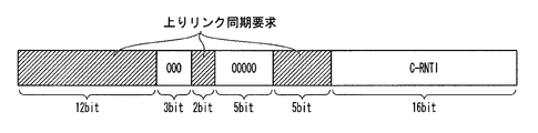
図3は、上りリンク再同期が必要なとき、すなわち上りリンク再同期要因が検出されたときに送信される、上りリンク同期要求を含んだ下りリンク制御用の情報のフォーマットを示す図である。上りリンク同期要求を含む下りリンク制御用の情報は、図3に示すように、同期が取れているときにリソース割当ての情報を配置している先頭の領域12ビットに「リソース割当てなし」を表す情報を配置する。移動局装置は、この「リソース割当てなし」を表す情報を検出すると、その下りリンク制御用の情報は上りリンク同期要求であると判定する。この「リソース割当てなし」の領域に続いて、リザーブ領域を3ビット配置する。このリザーブ領域には、下りリンク制御用の情報にて上りリンク同期要求以外の情報を伝送可能とするときに、伝送する情報を識別する値を配置するようにしてもよい。 FIG. 3 is a diagram illustrating a format of information for downlink control including an uplink synchronization request transmitted when uplink resynchronization is necessary, that is, when an uplink resynchronization factor is detected. As shown in FIG. 3, the downlink control information including the uplink synchronization request represents “no resource allocation” in the first 12 bits of the resource allocation information when synchronization is established. Arrange information. When the mobile station apparatus detects the information indicating “no resource allocation”, the mobile station apparatus determines that the downlink control information is an uplink synchronization request. Following this “no resource allocation” area, a reserve area of 3 bits is arranged. In the reserved area, when information other than an uplink synchronization request can be transmitted using information for downlink control, a value for identifying information to be transmitted may be arranged.
このリザーブ領域の次の「種別」には、シグネチャの種別を示す情報の領域を2ビット配置する。シグネチャの種別とは、専用シグネチャなのか、ランダムシグネチャかを示す。ここで、専用シグネチャは、基地局装置から上りリンク同期要求にて指定された移動局装置のみがランダムアクセスに用いるシグネチャである。この「種別」の領域の次の「シグネチャ」には、シグネチャの種別が専用シグネチャのときにシグネチャID番号を指定する領域を6ビット配置する。その次の「フレーム番号」には、シグネチャの種別が専用シグネチャのときに、「シグネチャ」の領域で指定したシグネチャID番号を使用可能な無線フレーム領域を指定する領域を4ビット配置する。予め有効期間などが仕様で定義されている場合は、使用可能無線フレーム領域を信号する必要はない。その次の「C−RNTI」は、上りリンクの同期が取れているときと同様に、この下りリンク制御用の情報が対象としている移動局装置識別情報を指定する領域であり、巡回冗長検査CRCを兼ねる領域を16ビット配置する。図1の下りリンク制御用の情報のときと同様に、巡回冗長検査CRCを算出し、その結果が自装置のC−RNTIであるか否かに基づき、自装置に対する情報であるか否かを判定する。 In the “type” next to the reserved area, an information area indicating the signature type is arranged in 2 bits. The signature type indicates whether it is a dedicated signature or a random signature. Here, the dedicated signature is a signature used for random access only by the mobile station device designated by the uplink synchronization request from the base station device. In the “signature” next to the “type” area, a 6-bit area for designating a signature ID number when the signature type is a dedicated signature is arranged. In the next “frame number”, when the signature type is a dedicated signature, a 4-bit area for designating a radio frame area that can use the signature ID number designated in the “signature” area is arranged. When the valid period is defined in the specification in advance, it is not necessary to signal the usable radio frame area. The next “C-RNTI” is an area for designating mobile station apparatus identification information targeted by this downlink control information, as in the case of uplink synchronization, and is a cyclic redundancy check CRC. An area that also serves as 16 bits is arranged. As in the case of the information for downlink control in FIG. 1, the cyclic redundancy check CRC is calculated, and whether or not the result is the information on the own device is determined based on whether or not the result is the C-RNTI of the own device. judge.
図1と図3に示したように、下りリンク制御用の情報は、上りリンクの同期が取れているときと、上りリンクの再同期が必要で上りリンク同期要求を送信するときとで、同じビット数の情報となっている。下りリンク共用制御チャネルPDCCHの下りリンク制御用の領域には、図1と図3に示したような下りリンク制御用の情報が、合計で予め決められた数だけ配置される。配置される下りリンク制御用の情報のうち、図1に示した上りリンクの同期が取れているときの情報と、図3に示した上りリンク同期要求を送信するときの情報との数の構成は、そのときの通信状態に応じた構成となる。すなわち、上りリンクの同期が取れているときの下りリンク制御用の情報を配置する領域に、上りリンクの再同期が必要なときに上りリンク同期要求を送信する下りリンク制御用の情報を配置する。 As shown in FIGS. 1 and 3, the downlink control information is the same when uplink synchronization is established and when uplink synchronization is required and uplink synchronization request is transmitted. It is information on the number of bits. In the downlink control area of the downlink shared control channel PDCCH, the downlink control information as shown in FIGS. 1 and 3 is arranged in a predetermined number in total. Of the downlink control information to be arranged, the number of the information when the uplink synchronization shown in FIG. 1 is established and the information when the uplink synchronization request shown in FIG. 3 is transmitted Is configured according to the communication state at that time. That is, information for downlink control for transmitting an uplink synchronization request when uplink resynchronization is required is arranged in an area for arranging information for downlink control when uplink synchronization is established .
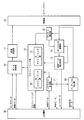
図4は、基地局装置の構成を示す概略ブロック図である。基地局装置は、データ制御部10、OFDM変調部11、スケジューリング部12、チャネル推定部13、DFT−S−OFDM復調部14、制御データ抽出部15、プリアンブル検出部16、シグネチャ管理部17、無線部19、上位層部30を具備する。スケジューリング部12は、DLスケジューリング部20、ULスケジューリング部21を具備する。なお、本実施形態においては、チャネル推定部13とULスケジューリング部21とは、各々、各移動局装置の上りリンク再同期要因を検出する再同期要因検出部として機能する。また、OFDM変調部111と無線部19とで、送信部として機能する。データ制御部10は、上位層部30から受けたユーザーデータと制御データとをスケジューリング部12からの指示により、制御データを下りリンク共通制御チャネル、下りリンク同期チャネル、下りリンクパイロットチャネル、下りリンク共用制御チャネルPDCCHにマッピングし、各移動局装置に対する送信データを下りリンク共用データチャネルDL−SCHにマッピングする。また、データ制御部10は、上りリンク制御用の情報と、下りリンク制御用の情報とをスケジューリング部12から受け、下りリンク共用制御チャネルPDCCHにマッピングする。すなわち、OFDM変調部11は、データ制御部10が各チャネルにマッピングしたデータを、データ変調、直列/並列変換、IFFT(Inverse Fast Fourier Transform:逆高速フーリエ)変換、CP(Cyclic Prefix)挿入、フィルタリングなどOFDM信号処理を行い、OFDM信号を生成する。無線部19は、OFDM変調部11が生成したOFDM変調信号を無線周波数にアップコンバートして、アンテナを介して移動局装置に送信する。
FIG. 4 is a schematic block diagram showing the configuration of the base station apparatus. The base station apparatus includes a
また、無線部19は、移動局装置からの上りリンクの信号をアンテナを介して受信し、ベースバンド信号にダウンコンバートした受信信号をDFT−S−OFDM復調部14、チャネル推定部13およびプリアンブル検出部16に渡す。チャネル推定部13は、受信信号中の上りリンクパイロットチャネルUPiCHから無線伝搬路特性を推定し、DFT−S−OFDM復調部14に、この推定結果を渡す。また、チャネル推定部13は、上りリンクのスケジューリングを行う為に、この推定結果をスケジューリング部12に渡す。
さらに、上りリンクの同期のずれを検知し、上りリンク同期が必要な場合にスケジューリング部12に報告する。尚、上りリンクの通信方式は、DFT−spread OFDM等のようなシングルキャリア方式を想定しているが、OFDM方式のようなマルチキャリア方式でもかまわない。
Also, the
Further, a shift in uplink synchronization is detected and reported to the
DFT−S−OFDM復調部14は、チャネル推定部13から受けた無線伝搬路特性と、制御データ抽出部15から受けたリソース割当て情報や適応変調のパラメータの情報などとを用いて、無線部19から受けた受信信号を復調して、受信データを得る。制御データ抽出部15では、受信データをユーザーデータ(上りリンク共用データチャネルUL−SCH)と制御データ(上りリンク共用制御チャネルPUCCH)に分離する。制御データ抽出部15は、制御データの中で下りリンクのCQI情報はスケジューリング部12に出力し、その他の制御データとユーザーデータは上位層部30に渡す。
The DFT-S-
スケジューリング部12は、前述のように下りリンクのスケジューリングを行うDLスケジューリング部20と上りリンクのスケジューリングを行うULスケジューリング部21を具備する。DLスケジューリング部20は移動局装置から通知されるCQI情報や上位層部30から通知される各ユーザーデータのスケジューリング情報から下りリンクの各チャネルにユーザーデータをマッピングする為のスケジューリングを行う。DLスケジューリング部20はスケジューリング結果に基づき、図1に示した同期が取れている移動局装置に対する下りリンク制御用の情報を生成し、データ制御部10に出力する。ULスケジューリング部21は、チャネル推定部13からの上りリンクの無線伝搬路推定結果と移動局装置からのリソース割当て要求から上りリンクの各チャネルにユーザーデータをマッピングする為のスケジューリングを行う。ULスケジューリング部21はスケジューリング結果に基づき、図2に示した同期が取れている移動局装置に対する上りリンク制御用の情報を生成し、データ制御部10に出力する。
As described above, the
また、ULスケジューリング部21は、タイマーを使って各移動局装置の上りリンク同期状況を管理し、一定時間、上りリンクによる送受信の無かった移動局装置を上りリンク再同期要因発生として検出する。ULスケジューリング部21は、このタイマーにより検出した上りリンク再同期が必要な移動局装置およびチャネル推定部13が検出した上りリンク再同期が必要な移動局装置について、上りリンク再同期要因の検出を上位層部30に通知するとともに、これらの移動局装置各々の上りリンク同期要求を含んだ下りリンク制御用の情報を生成し、データ制御部10に出力する。ULスケジューリング部21は、上りリンク同期要求を含んだ下りリンク制御用の情報を生成する際に、シグネチャ管理部17から使用可能な専用シグネチャのシグネチャID番号を取得し、下りリンク制御用の情報に格納するとともに、シグネチャ管理部17に、該シグネチャID番号を使用する移動局装置を識別する情報と、使用する無線フレーム番号とを登録する。
Further, the
プリアンブル検出部16は、無線部19から受けた受信信号から同期ずれ測定用信号であるプリアンブルを検出し、さらに同期タイミングずれ量を算出する。プリアンブル検出部16は、検出したプリアンブルから取得したシグネチャID番号(測定用信号識別情報)と、算出した同期タイミングずれ量とを上位層部30に報告する。プリアンブル検出部16は、取得したシグネチャID番号が、シグネチャ管理部17から通知されたシグネチャの場合は、専用シグネチャフラグを1に設定し、シグネチャ管理部から通知されていないシグネチャの場合は、専用シグネチャフラグを0に設定する。また、プリアンブル検出部16は、取得したシグネチャID番号が、シグネチャ管理部17から通知されたシグネチャの場合は、シグネチャ管理部17に通知されたシグネチャID番号のプリアンブルを検出したことを報告する。
The
シグネチャ管理部17は、ULスケジューリング部21からの指示により、専用シグネチャを選択し、選択した専用シグネチャのID番号をULスケジューリング部21に通知する。また、選択したシグネチャをプリアンブル検出部16に通知する。シグネチャ管理部17は、専用シグネチャ選択の際は、使用している専用シグネチャのシグネチャID番号を確認し、使用している専用シグネチャを除いた中から選択する。シグネチャ管理部17は、選択されたシグネチャID番号を使用中として登録し、プリアンブル検出部16で検出されたシグネチャを保存内容から削除する。上位層部30は、後述の図6から図11で説明する手順を行うように基地局装置を制御する。
The
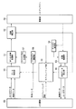
図5は、移動局装置の構成を示す概略ブロック図である。移動局装置は、データ制御部50、DFT−S−OFDM変調部51、スケジューリング部52、OFDM復調部53、チャネル推定部54、制御データ抽出部55、同期補正部56、プリアンブル生成部57、シグネチャ選択部58、無線部59、上位層部60を具備する。
ユーザーデータと制御データは、データ制御部50に入力され、スケジューリング部52からの指示により上りリンク共用データチャネルUL−SCHにマッピングされる。DFT−S−OFDM変調部51は、データ制御部50がマッピングしたデータを、データ変調、DFT変換、サブキャリアマッピング、IFFT変換、CP(Cyclic Prefix)挿入、フィルタリングなどDFT−S−OFDM信号処理を行い、DFT−Spread−OFDM信号を生成する。上りリンクの通信方式は、DFT−spred OFDMのようなシングルキャリア方式を想定しているが、OFDM方式のようなマルチキャリア方式でもかまわない。同期補正部56は、制御データ抽出部55から渡された同期情報から送信タイミングを決定し、DFT−S−OFDM変調部51から受けたDFT−Spread−OFDM信号を、送信タイミングに合うように無線部59に渡す。無線部59は、無線制御部から指示された無線周波数に設定し、同期補正部56から受けたDFT−Spread−OFDM信号を無線周波数にアップコンバートし、アンテナを介して基地局装置に送信する。
FIG. 5 is a schematic block diagram showing the configuration of the mobile station apparatus. The mobile station apparatus includes a
User data and control data are input to the
また、無線部59は、基地局装置からの下りリンクの信号を、アンテナを介して受信し、ベースバンド信号にダウンコンバートして、このベースバンド信号をOFDM復調部53とチャネル推定部54とに渡す。チャネル推定部54は、無線部59から受けた信号中の下りリンクパイロットチャネルから無線伝搬路特性を推定し、OFDM復調部53とスケジューリング部52とに推定結果を渡す。また、チャネル推定部54は、基地局装置に無線伝搬路特性の推定結果を通知する為にCQI(Channel Quality Indicator)情報に変換し、データ制御部50にCQI情報を渡す。OFDM復調部53は、チャネル推定部54の無線伝搬路推定結果を用いて無線部59から受けたベースバンド信号を復調し、受信データを得る。制御データ抽出部55は、この受信データをユーザーデータと制御データに分離する。
Also, the
制御データ抽出部55は、分離した制御データの中から、自装置に対する上りリンク制御用の情報を抽出し、この情報をスケジューリング部52に渡し、さらに、自装置に対する上りリンクの同期情報を抽出し、この情報は同期補正部56に渡す。また、制御データ抽出部55は、分離した制御データの中から自装置に対する下りリンク制御用の情報を抽出し、この情報が上りリンクの同期が取れている移動局装置に対する下りリンク制御用の情報のときは、該情報のリソース割当てで指示されたリソースのユーザーデータおよび制御データを、該情報の適応変調のパラメータで指示された変調方式でベースバンド信号から復調するように、OFDM復調部53に指示する。一方、抽出した自装置に対する下りリンク制御用の情報が上りリンク同期要求を含んだ下りリンク制御用の情報のときは、該情報に従った同期ずれ計測用信号の送信を行うために、該情報を上位層部60に渡す。また、これ以外の制御データとユーザーデータについても、上位層部60に渡す。制御データ抽出部55は、抽出した下りリンク制御用の情報が上りリンクの同期が取れている移動局装置に対する下りリンク制御用の情報であるか、上りリンク同期要求を含んだ下りリンク制御用の情報であるかを、該情報のリソース割当ての領域を参照し、割当てられているリソースが指定されているときは、上りリンクの同期が取れている移動局装置に対する下りリンク制御用の情報であると判定し、割当てられているリソースがないときは、上りリンク同期要求を含んだ下りリンク制御用の情報であると判定する。
The control
シグネチャ選択部58は、上位層部60からの指示により、ランダムアクセスで使用するシグネチャID番号を選択し、選択したシグネチャID番号をプリアンブル生成部57に渡す。プリアンブル生成部(測定用信号生成部)57は、シグネチャ選択部58が選択したシグネチャID番号でプリアンブル(同期ずれ測定用信号)を生成し、DFT−S−OFDM変調部51に渡す。スケジューリング部52は、MAC制御を行い、基地局装置から指示されたリソースを使ってデータを送受信することを制御する。また、タイマーを使って各移動局装置の上りリンク同期状況を管理する。上位層部60は、後述の図6から図12で説明する手順を行うように移動局装置を制御する。
The signature selection unit 58 selects a signature ID number to be used for random access according to an instruction from the
本実施形態では、上りリンク再同期が必要な状態にある移動局装置への上りリンク同期要求の際、基地局装置は、下りリンク共用制御チャネルPDCCHで上りリンク同期要求を送信する。移動局装置は、上りリンク同期要求に専用シグネチャが含まれている場合は、該専用シグネチャを用いた衝突なしランダムアクセスRACHを送信する。以下に具体的に説明する。図6は、基地局装置が専用シグネチャを含んだ上りリンク同期要求を送信した場合の手順であり、図7は、基地局装置がランダムシグネチャを指定した上りリンク同期要求を送信した場合の手順であり、図8は、移動局装置が上りリンク同期要求を含んだ下りリンク共用制御チャネルPDCCHを受信できなかった場合の手順である。 In the present embodiment, when an uplink synchronization request is made to a mobile station apparatus in a state where uplink resynchronization is necessary, the base station apparatus transmits an uplink synchronization request using the downlink shared control channel PDCCH. When a dedicated signature is included in the uplink synchronization request, the mobile station device transmits a collision-free random access RACH using the dedicated signature. This will be specifically described below. FIG. 6 shows a procedure when the base station apparatus transmits an uplink synchronization request including a dedicated signature, and FIG. 7 shows a procedure when the base station apparatus transmits an uplink synchronization request designating a random signature. FIG. 8 shows the procedure when the mobile station apparatus cannot receive the downlink shared control channel PDCCH including the uplink synchronization request.
図6は、基地局装置が専用シグネチャを含んだ上りリンク同期要求を送信した場合の手順を説明するシーケンス図である。基地局装置は、移動局装置の上りリンク同期を管理している。基地局装置のULスケジューリング部21は、タイマーを設定し、ある一定期間、上りリンクの送信がない状態が継続した場合や、上りリンク同期情報の更新がない状態が継続した場合に、上りリンク再同期要因発生と判定する。また、チャネル推定部13は、移動局装置からの上りリンクの送信データまたは送信信号を受信し、受信タイミングのずれを検知した場合に、上りリンク再同期要因発生と判定する。基地局装置は、上りリンク再同期が必要な移動局装置、すなわち上りリンク再同期要因発生と判定した移動局装置に対するデータ(送信データおよび受信データ)の到着を検知する、または、基地局装置が、上りリンク再同期要因発生と判定した移動局装置に対して上りリンク同期を継続させることを決定した際に、上りリンク同期要求を送信する。ULスケジューリング部21が、上りリンク同期要求を含んだ下りリンク制御用の情報を生成し、該情報を、データ制御部10が下りリンク共用制御チャネルPDCCHにマッピングして、送信する(信号6−1)。この上りリンク同期要求は、図3にて示したフォーマットを有する。この上りリンク同期要求には、ULスケジューリング部21がシグネチャ管理部17から取得した専用シグネチャを指定する情報であるシグネチャID番号が含まれている。また、シグネチャ管理部17に、該シグネチャID番号と送信先の移動局装置のC−RNTIとを対応付けて格納する。
FIG. 6 is a sequence diagram illustrating a procedure when the base station apparatus transmits an uplink synchronization request including a dedicated signature. The base station apparatus manages uplink synchronization of the mobile station apparatus. The
移動局装置の制御データ抽出部55は、下りリンク共用制御チャネルPDCCHの各下りリンク制御用の情報について巡回冗長検査CRCを算出して、自装置のC−RNTIと一致するものを探し出し、自装置に対する下りリンク制御用の情報を正確に受信できたことを検知する。制御データ抽出部55は、下りリンク制御用の情報のリソース割当て情報が、「リソース割当てなし」となっていることから該情報が上りリンク同期要求であることを検知する。上位層部60は、この上りリンク同期要求を受けると、該上りリンク同期要求にて指定されたシグネチャID番号とフレーム番号とを、シグネチャ選択部58に指定する。シグネチャ選択部58は、指定されたシグネチャID番号の専用シグネチャを選択し、該専用シグネチャと、指定されたフレーム番号とを、プリアンブル生成部57に指定する。プリアンブル生成部57は、指定された専用シグネチャのプリアンブルを生成し、DFT−S−OFDM変調部51は、このプリアンブルを、指定されたフレーム番号の無線フレーム内のランダムアクセスチャネルRACHを用いて送信する(信号6−2:メッセージ1)。
The control
基地局装置のプリアンブル検出部16は、ランダムアクセスチャネルでプリアンブルを検出すると、上位層部30は該プリアンブルに対するプリアンブル応答を生成し、送信する(信号6−3:メッセージ2)。このとき基地局装置の上位層部30は、プリアンブルから検出した専用シグネチャと、シグネチャ管理部17の登録内容とを比較することにより、検出したプリアンブルの送信元の移動局装置を特定することが可能である。上位層部30は、特定した移動局装置の識別情報であるC−RNTIを、シグネチャ管理部17から取得する。データ制御部10は、プリアンブル応答を、下りリンク共用制御チャネルPDCCHと下りリンク共用データチャネルDL−SCHとに分けてマッピングする。下りリンク共用制御チャネルPDCCHにマッピングする情報には、プリアンブル応答であることを識別するRA−RNTI(Random Access−Radio Network Tempolary Identity)かまたは、移動局装置を直接指定するセル内移動局識別情報C−RNTIが含まれており、下りリンク共用データチャネルDL−SCHには、同期ずれの補正量を指示する同期情報が含まれている。
When the
RA−RNTIが使用される場合には、下りリンク共用データチャネルDL−SCHに、専用シグネチャまたはC−RNTIが含まれる。移動局装置では、制御データ抽出部55が専用シグネチャまたはC−RNTIを検出することで、自装置に対するプリアンブル応答を検出する。制御データ抽出部55は、このプリアンブル応答から同期情報を抽出し、該同期情報の指示に従った同期ずれの補正量を同期補正部56に指示する。続いて、基地局装置から通常のデータ送信が再開される(信号6−4、信号6−5)。
When RA-RNTI is used, a dedicated signature or C-RNTI is included in the downlink shared data channel DL-SCH. In the mobile station device, the control
図7は、基地局装置が専用シグネチャを送信しない場合の手順を説明するシーケンス図である。基地局装置は、移動局装置の上りリンク同期を管理している。基地局装置のULスケジューリング部21は、タイマーを設定し、ある一定期間、上りリンクの送信がない状態が継続した場合や、上りリンク同期情報の更新がない状態が継続した場合に、上りリンク再同期要因発生と特定する。または、チャネル推定部13は、移動局装置からの上りリンクの送信データまたは送信信号を受信し、受信タイミングのずれを検知した場合に、上りリンク再同期要因発生と特定する。基地局装置は、上りリンク同期再同期が必要な移動局装置に対するデータ(送信データおよび受信データ)の到着を検知する、または、基地局装置が上りリンク再同期が必要な移動局装置に対して上りリンク同期を継続させることを決定した際に、上りリンク同期要求を送信する。ULスケジューリング部21が、上りリンク同期要求を含んだ下りリンク制御用の情報を生成し、該情報を、データ制御部10が下りリンク共用制御チャネルPDCCHにマッピングして、送信する(信号7−1)。ここで、上りリンク同期要求では、「種別」の領域にてランダムシグネチャを指定されており、これにより、専用シグネチャが割当てられないことを示している。
FIG. 7 is a sequence diagram illustrating a procedure when the base station apparatus does not transmit a dedicated signature. The base station apparatus manages uplink synchronization of the mobile station apparatus. The
移動局装置の制御データ抽出部55は、下りリンク共用制御チャネルPDCCHの各下りリンク制御用の情報について巡回冗長検査CRCを算出して、自装置のC−RNTIと一致するものを探し出し、自装置に対する下りリンク制御用の情報を正確に受信できたことを検知する。制御データ抽出部55は、下りリンク制御用の情報のリソース割当て情報が、「リソース割当てなし」となっていることから該情報が上りリンク同期要求であることを検知する。上位層部60は、この上りリンク同期要求を受けると、シグネチャ選択部58にシグネチャの選択を指示する。シグネチャ選択部58は、専用シグネチャ以外のシグネチャID番号のシグネチャをランダムに選択し、該シグネチャを含むプリアンブルの生成を、プリアンブル生成部57に指示する。プリアンブル生成部57は、指示されたシグネチャのプリアンブルを生成し、DFT−S−OFDM変調部51は、このプリアンブルをランダムアクセスチャネルRACHを用いて送信する(信号7−2:メッセージ1)。
The control
基地局装置のプリアンブル検出部16は、ランダムアクセスチャネルでプリアンブルを検出すると、上位層部30は該プリアンブルに対するプリアンブル応答を生成し、送信する(信号7−3:メッセージ2)。このとき基地局装置の上位層部30は、シグネチャの検出では、移動局装置の特定ができない。データ制御部10は、プリアンブル応答を、下りリンク共用制御チャネルPDCCHと下りリンク共用データチャネルDL−SCHとに分けてマッピングする。下りリンク共用制御チャネルPDCCHには、プリアンブル応答であることを識別するRA−RNTIが含まれており、下りリンク共用データチャネルDL−SCHには、同期情報とシグネチャのマッピング情報、シグネチャと新しいセル内移動局装置識別情報C−RNTI(T−C−RNTI)のマッピング情報、メッセージ2に対する移動局装置の応答であるメッセージ3を送信するためのスケジューリング情報が含まれている。
When the
この時点で、基地局装置は、移動局装置が何を理由にランダムアクセスをしてきたのか把握できない。移動局装置は、メッセージ3のスケジューリング情報に従って、メッセージ3を送信する(信号7−4:メッセージ3)。メッセージ3には、送信元移動局装置を識別するセル内移動局装置識別情報C−RNTIを含める。基地局装置は、C−RNTIを含んだメッセージ3を受信すると、このメッセージ3が先に送信したスケジューリング情報に従って送信されていることから、信号7−1で指示された移動局装置からの応答であることを検知する。基地局装置は、このメッセージ3に対応するメッセージ1のプリアンブルで複数の移動局装置が同時に同じシグネチャを使った送信をしていた場合の衝突解決情報としてコンテンションレゾリューションを送信する(信号7−5:メッセージ4)。メッセージ4を配置した下りリンク共用制御チャネルPDCCHには、メッセージ2で基地局装置が指定した新しいセル内移動局装置識別情報T−C−RNTIが含まれており、下りリンク共用データチャネルDL−SCHには、メッセージ3で基地局装置が検知した移動局装置識別情報が含まれる。続いて、基地局装置から通常のデータ送信が再開される。(信号7−6、信号7−7)
At this point, the base station apparatus cannot grasp why the mobile station apparatus has performed random access. The mobile station apparatus transmits message 3 according to the scheduling information of message 3 (signal 7-4: message 3). The message 3 includes in-cell mobile station apparatus identification information C-RNTI for identifying the source mobile station apparatus. When receiving the message 3 including the C-RNTI, the base station apparatus transmits the message 3 according to the previously transmitted scheduling information. Therefore, the base station apparatus returns a response from the mobile station apparatus indicated by the signal 7-1. Detect something. The base station apparatus transmits contention resolution as collision resolution information when a plurality of mobile station apparatuses are simultaneously transmitting using the same signature in the preamble of
図8は、移動局装置が、下りリンク共用制御チャネルPDCCHの巡回冗長検査CRCチェックを失敗した場合の手順を説明するシーケンス図である。基地局装置は、移動局装置の上りリンク同期を管理している。例えば、タイマーを設定し、ある一定期間、上りリンクの送信がない状態が継続した場合や、上りリンク同期情報の更新がない状態が継続した場合に、上りリンク再同期要因発生と特定する。または、移動局装置からの上りリンクの送信データまたは送信信号を受信し、受信タイミングのずれを検知した場合に、上りリンク再同期要因発生と特定する。基地局装置は、上りリンク再同期が必要な移動局装置に対するデータの到着を検知する、または、基地局装置が上りリンク再同期が必要な移動局装置に対して上りリンク同期を継続させることを決定した際に、上りリンク同期要求を送信する。上りリンク同期要求は、下りリンク共用制御チャネルPDCCHで送信される(信号8−1)。 FIG. 8 is a sequence diagram illustrating a procedure when the mobile station apparatus fails the cyclic redundancy check CRC check of the downlink shared control channel PDCCH. The base station apparatus manages uplink synchronization of the mobile station apparatus. For example, a timer is set, and when there is no uplink transmission for a certain period of time, or when there is no uplink synchronization information update, the occurrence of an uplink resynchronization factor is identified. Alternatively, when uplink transmission data or a transmission signal is received from the mobile station apparatus and a shift in reception timing is detected, the occurrence of an uplink resynchronization factor is identified. The base station apparatus detects the arrival of data to the mobile station apparatus that requires uplink resynchronization, or the base station apparatus continues uplink synchronization for the mobile station apparatus that requires uplink resynchronization. When the determination is made, an uplink synchronization request is transmitted. The uplink synchronization request is transmitted on the downlink shared control channel PDCCH (signal 8-1).
移動局装置の制御データ抽出部55は、下りリンク共用制御チャネルPDCCHの各下りリンク制御用の情報について巡回冗長検査CRCを算出して、自装置のC−RNTIと一致するものを探し出すが、ここでは該当する移動局装置の受信状況が悪いなどの理由で、正確に受信できず、一致しなかったとする。移動局装置は、上りリンク同期要求を検知できないため、次の受信サイクルまで受信を停止し、再度下りリンク共用制御チャネルPDCCHの受信動作を行う。基地局装置は、定められたウインドウタイム内に移動局装置からの応答(応答方法は、上記の図6〜図7の状況によって異なる)を得られない場合に、移動局装置が上りリンク同期要求を受信できなかったことを検知する。基地局装置は、移動局装置の非受信を検出すると、次の送信サイクルまで待機し、再度上りリンク再同期が必要な移動局装置に対する上りリンク同期要求手続を行う(信号8−2)。
The control
図9は、移動局装置が、下りリンク共用制御チャネルPDCCHの巡回冗長検査CRCチェックを失敗した場合の図8とは異なるもう一つの手順を説明するシーケンス図である。基地局装置は、移動局装置の上りリンク同期を管理している。例えば、タイマーを設定し、ある一定期間、上りリンクの送信がない状態が継続した場合や、上りリンク同期情報の更新がない状態が継続した場合に、上りリンク再同期要因発生と特定する。または、移動局装置からの上りリンクの送信データまたは送信信号を受信し、受信タイミングのずれを検知した場合に、上りリンク再同期要因発生と特定する。基地局装置は、上りリンク再同期が必要な移動局装置に対するデータの到着を検知する、または、基地局装置が上りリンク再同期が必要な移動局装置に対して上りリンク同期を継続させることを決定した際に、上りリンク同期要求を送信する。上りリンク同期要求は、下りリンク共用制御チャネルPDCCHで送信される(信号9−1)。 FIG. 9 is a sequence diagram illustrating another procedure different from FIG. 8 when the mobile station apparatus fails the cyclic redundancy check CRC check of the downlink shared control channel PDCCH. The base station apparatus manages uplink synchronization of the mobile station apparatus. For example, a timer is set, and when there is no uplink transmission for a certain period of time, or when there is no uplink synchronization information update, the occurrence of an uplink resynchronization factor is identified. Alternatively, when uplink transmission data or a transmission signal is received from the mobile station apparatus and a shift in reception timing is detected, the occurrence of an uplink resynchronization factor is identified. The base station apparatus detects the arrival of data to the mobile station apparatus that requires uplink resynchronization, or the base station apparatus continues uplink synchronization for the mobile station apparatus that requires uplink resynchronization. When the determination is made, an uplink synchronization request is transmitted. The uplink synchronization request is transmitted on the downlink shared control channel PDCCH (signal 9-1).
移動局装置の制御データ抽出部55は、下りリンク共用制御チャネルPDCCHの各下りリンク制御用の情報について巡回冗長検査CRCを算出して、自装置のC−RNTIと一致するものを探し出すが、ここでは該当する移動局装置の受信状況が悪いなどの理由で、正確に受信できず、一致しなかったとする。移動局装置は、上りリンク同期要求を検知できないため、次の上りリンクの送信を行ってしまう(信号9−2)。ここで上りリンクの送信とは、下りリンク共用制御チャネルPDCCHで指定される動的な上りリンク送信ではなく、Layer3レベルのRRCシグナリングなどで予め送信方法、送信リソースなどが設定されている上りリンク共用データチャネルUL−SCHで送信されるデータ送信や上りリンク共用制御チャネルPUCCHで送信されるCQIフィードバックチャネルなどの送信である。この上りリンクの送信を基地局装置が検出した場合に、移動局装置が上りリンク同期要求を受信できなかったことを検知する。基地局装置は、移動局装置の非受信を検出すると、再度上りリンク再同期が必要な移動局装置に対する上りリンク同期要求手続を行う(信号9−3)。ただし、信号9−2の上りリンクの送信は、上りリンク同期が取れていない移動局装置からの送信であるため、基地局装置がこの信号9−2を正確に検知できるかどうかは移動局装置の送信タイミングや無線状況に依存する。よって、このシーケンスは、図8で説明したシーケンスの補助的な役割として機能する。
The control
図10は、基地局装置の上りリンク同期要求送信処理の処理手順を示すフローチャートである。基地局装置では、ULスケジューリング部21またはチャネル推定部13が上りリンクの再同期要因を検出して、上りリンク同期要求を送信することを決定すると(Sa1)、ULスケジューリング部21は、専用シグネチャの割当てが可能かどうかを、シグネチャ管理部17を参照して確認する。専用シグネチャを割当てることが可能な場合(Sa2−Yes)、専用シグネチャを選択する(Sa3)。次に、ULスケジューリング部21は、ステップSa3にて「種別」の領域に専用シグネチャを登録し、「シグネチャ」の領域に選択した専用シグネチャのシグネチャID番号を登録した上りリンク同期要求を含む下りリンク制御用の情報を生成し、この情報を、データ制御部10が下りリンク共用制御チャネルPDCCHにマッピングして送信する(Sa4)。
FIG. 10 is a flowchart showing a processing procedure of uplink synchronization request transmission processing of the base station apparatus. In the base station apparatus, when the
一方、ステップSa2にて、専用シグネチャを割当てることが不可能な場合(Sa2−No)、ULスケジューリング部21は、「種別」の領域にランダムシグネチャを登録した上りリンク同期要求を含む下りリンク制御用の情報を生成し、この情報を、データ制御部10が下りリンク共用制御チャネルPDCCHにマッピングして送信する(Sa6)。ステップSa4もしくはステップSa6にて上りリンク同期要求を含む下りリンク制御用の情報を送信すると、上位層部30は、予め定められたウインドウタイム以内、すなわち上りリンク同期要求の「フレーム番号」にて指定した無線フレームにて、プリアンブル検出部16が、上りリンク同期要求に対する応答であるプリアンブルを受け取ったかどうかを判断し、受け取っていない場合は(Sa5−No)、ステップSa2に戻って、もう一度、上りリンク同期要求の手順を行う。一方、ステップSa5にて、応答のプリアンブルを受け取ったと判定した場合は(Sa5−Yes)、上りリンク同期要求送信処理の処理を終了する。
On the other hand, when it is impossible to assign a dedicated signature in step Sa2 (Sa2-No), the
図11は、基地局装置のランダムアクセス受信処理手順の処理手順を示すフローチャートである。基地局装置のプリアンブル検出部16は、ランダムアクセスチャネルにて、プリアンブルを検知すると、シグネチャ管理部17を参照して、そのプリアンブルのシグネチャが専用シグネチャか否かを判定する(Sb1)。このステップSb1にて専用シグネチャと判定した場合は、プリアンブル検出部16が、プリアンブルを検出した際に計測した同期ずれを上位層部30に通知する。この同期ずれを受けた上位層部30は、この同期ずれの同期情報を含むプリアンブル応答をデータ制御部10に出力して送信し(Sb2)、ランダムアクセス受信処理を終了する。一方、ステップSb1にて専用シグネチャでないと判定した場合は、上位層部30は、同期情報と図7のメッセージ3のスケジューリング情報を含むプリアンブル応答をデータ制御部10に出力して送信し(Sb3)、メッセージ3の受信処理に入る。メッセージ3を受信すると(Sb4)、これを受けた上位層部30は、メッセージ3内に上りリンク同期要求の移動局装置のC−RNTIが含まれるかどうかを確認する(Sb5)。それ以外の移動局装置のC−RNTIや他のIDを検知した場合は、別要因のランダムアクセス処理を行う(Sb5−No)。上りリンク同期要求の移動局装置のC−RNTIを検知した場合(Sb5−Yes)、上位層部30は、図7のメッセージ4を生成して、データ制御部10に出力して送信し(Sb6)、ランダムアクセス受信処理を終了する。
FIG. 11 is a flowchart illustrating a processing procedure of a random access reception processing procedure of the base station apparatus. When the
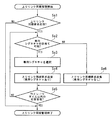
図12は、移動局装置の上りリンク同期管理処理の処理手順を示すフローチャートである。移動局装置の制御データ抽出部55は、下りリンク共用制御チャネルPDCCHで自装置のC−RNTIを検出すると(Sc1)、リソース割当ての領域が「リソース割当てなし」であるか否かを判定し、上りリンク同期要求かどうかを識別する(Sc2)。このステップSc2にて上りリンク同期要求ではないと判定した場合(Sc2−No)、通常のデータ送受信を行う。一方、ステップSc2にて上りリンク同期要求であると判定した場合(Sc2−Yes)、制御データ抽出部55からこの上りリンク同期要求を受けた上位層部60は、上りリンク同期要求の種別の領域からシグネチャの種別を示す情報を取得し、専用シグネチャを含んでいるかどうかを判定するとともに(Sc3)、上りリンクの送信を停止する。
FIG. 12 is a flowchart showing a processing procedure of uplink synchronization management processing of the mobile station apparatus. When the control
ステップSc3にて、専用シグネチャが含まれていると判定した場合は(Sc3−Yes)、上位層部60は、シグネチャ選択部58を介してプリアンブル生成部57に専用シグネチャのプリアンブル送信を指示する。プリアンブル生成部57は指示された専用シグネチャのプリアンブルを生成し、DFT−S−OFDM変調部51に出力して送信する(Sc4)。移動局装置は、専用シグネチャでプリアンブルを送信すると、該プリアンブルに対する応答である図6のメッセージ2を受信する(Sc5)。制御データ抽出部55は、このメッセージ2から同期情報を取得して、同期補正部56に該同期情報を設定した後、移動局装置は、データ送受信を継続する。
If it is determined in step Sc3 that the dedicated signature is included (Sc3-Yes), the
一方、ステップSc3にて、専用シグネチャが含まれていないと判定した場合は(Sc3−No)、上位層部60は、シグネチャ選択部58にランダムにシグネチャを選択するように指示する。シグネチャ選択部58は、この指示を受けるとランダムにシグネチャを選択し、選択したシグネチャのシグネチャID番号をプリアンブル生成部57に出力する。プリアンブル生成部57は、このシグネチャID番号のシグネチャのプリアンブル生成し、DFT−S−OFDM変調部51に出力して送信する(Sc6)。移動局装置は、ランダムに選択したシグネチャでプリアンブルを送信すると、該プリアンブルに対する応答である図7のメッセージ2を受信する(Sc7)。移動局装置は、このメッセージ2から、同期情報とシグネチャのマッピング情報、シグネチャと新しいC−RNTI(T−C−RNTI)のマッピング情報、メッセージ3のスケジューリング情報を取得する。移動局装置は、取得したスケジューリング情報に従いメッセージ3を自身のC−RNTIを含んで送信する(Sc8)。移動局装置は、メッセージ4を受信後(Sc9)、データ送受信を継続する。
On the other hand, when it is determined in step Sc3 that the dedicated signature is not included (Sc3-No), the
このように、本実施形態では、基地局装置と移動局装置との間で上りリンクの時間の同期がとれているときには、通信のパラメータの伝送に用いられている下りリンク共用制御チャネルPDCCHの下りリンク制御用の情報の領域に、リソース割当ての領域に「リソース割当てなし」として上りリンクの同期がとれているときの通信のパラメータと識別できるように上りリンク同期要求を配置することで、優れた無線リソースの利用効率を得ることができる。これは、上りリンク同期要求を送信するときは、必ず上りリンク再同期が必要なので、上りリンクの同期がとれているときの通信のパラメータを伝送する必要がないということと、上りリンクの同期がとれているときの通信のパラメータとして、「リソース割当てなし」を伝送することはないということを利用している。 As described above, in this embodiment, when the uplink time is synchronized between the base station apparatus and the mobile station apparatus, the downlink shared control channel PDCCH used for transmission of communication parameters is downlinked. By placing an uplink synchronization request in the information area for link control so that it can be identified from the communication parameters when the uplink is synchronized as “no resource assignment” in the resource assignment area, Utilization efficiency of radio resources can be obtained. This is because uplink resynchronization is always required when transmitting an uplink synchronization request, so there is no need to transmit communication parameters when uplink synchronization is established, and uplink synchronization is The fact that “no resource allocation” is not transmitted is used as a communication parameter when it is taken.
さらに、下りリンク共用制御チャネルPDCCHの物理的なフォーマットは、上りリンクの同期が取れているときの通信パラメータと、上りリンク同期要求とで共用している。このため、移動局装置の動作として、通常の下りリンク共用制御チャネルの受信過程において、データ処理によって「リソース割当てなし」を検出したときは、上りリンク同期要求であると判定すれば良く、物理的な特別な処理で上りリンク同期要求を受信する必要がない。このように移動局装置は、通常のデータ受信手続の中で上りリンク同期要求を受信できるため、基地局装置は、どのタイミングにおいても上りリンク同期要求を送信することが可能となる。 Further, the physical format of the downlink shared control channel PDCCH is shared by the communication parameters when uplink synchronization is established and the uplink synchronization request. For this reason, as an operation of the mobile station apparatus, when “no resource allocation” is detected by data processing in the reception process of a normal downlink shared control channel, it may be determined that the request is an uplink synchronization request, It is not necessary to receive the uplink synchronization request by special processing. As described above, since the mobile station apparatus can receive the uplink synchronization request during the normal data reception procedure, the base station apparatus can transmit the uplink synchronization request at any timing.
本実施形態において、上りリンク同期要求は、図3のようにして下りリンク制御用の情報の領域に配置したが、図13のようにMCSやペイロードサイズの領域を「0」にすることや上りリンクリソース割当ての情報を配置している10ビットに「リソース割当てなし」を示す情報を配置することで、上りリンク同期要求であることを識別可能とし、上りリンク制御用の情報の領域に配置してもよい。また、図14のように、下りリンク制御用の情報の領域であっても、MCSやペイロードサイズの領域を「0」にすることで、上りリンク同期要求であることを識別可能としてもよい。
また、上りリンク同期要求を、下りリンク制御用の情報の領域と、上りリンク制御用の情報の領域とのどちらでも配置できるようにしてもよい。
In this embodiment, the uplink synchronization request is arranged in the downlink control information area as shown in FIG. 3, but the MCS and payload size areas are set to “0” as shown in FIG. By placing information indicating “no resource assignment” in the 10 bits where link resource allocation information is allocated, it is possible to identify an uplink synchronization request, and the information is allocated in the information area for uplink control. May be. Further, as shown in FIG. 14, even if it is an area for information for downlink control, it may be possible to identify an uplink synchronization request by setting the area of MCS or payload size to “0”.
Further, the uplink synchronization request may be arranged in either the downlink control information area or the uplink control information area.
また、図4における上位層部30、データ制御部10、OFDM変調部11、スケジューリング部12、チャネル推定部13、DFT−S−OFDM復調部14、制御データ抽出部15、プリアンブル検出部16、シグネチャ管理部17、もしくは、図5における上位層部60、データ制御部50、DFT−S−OFDM変調部51、スケジューリング部52、OFDM復調部53、チャネル推定部54、制御データ抽出部55、同期補正部56、プリアンブル生成部57、シグネチャ選択部58の機能を実現するためのプログラムをコンピュータ読み取り可能な記録媒体に記録して、この記録媒体に記録されたプログラムをコンピュータシステムに読み込ませ、実行することにより各部の処理を行ってもよい。なお、ここでいう「コンピュータシステム」とは、OSや周辺機器等のハードウェアを含むものとする。
Also, the
また、「コンピュータシステム」は、WWWシステムを利用している場合であれば、ホームページ提供環境(あるいは表示環境)も含むものとする。
また、「コンピュータ読み取り可能な記録媒体」とは、フレキシブルディスク、光磁気ディスク、ROM、CD−ROM等の可搬媒体、コンピュータシステムに内蔵されるハードディスク等の記憶装置のことをいう。さらに「コンピュータ読み取り可能な記録媒体」とは、インターネット等のネットワークや電話回線等の通信回線を介してプログラムを送信する場合の通信線のように、短時間の間、動的にプログラムを保持するもの、その場合のサーバやクライアントとなるコンピュータシステム内部の揮発性メモリのように、一定時間プログラムを保持しているものも含むものとする。また上記プログラムは、前述した機能の一部を実現するためのものであっても良く、さらに前述した機能をコンピュータシステムにすでに記録されているプログラムとの組み合わせで実現できるものであっても良い。
Further, the “computer system” includes a homepage providing environment (or display environment) if a WWW system is used.
The “computer-readable recording medium” refers to a portable medium such as a flexible disk, a magneto-optical disk, a ROM, and a CD-ROM, and a storage device such as a hard disk built in the computer system. Furthermore, the “computer-readable recording medium” dynamically holds a program for a short time like a communication line when transmitting a program via a network such as the Internet or a communication line such as a telephone line. In this case, a volatile memory in a computer system serving as a server or a client in that case, and a program that holds a program for a certain period of time are also included. The program may be a program for realizing a part of the functions described above, and may be a program capable of realizing the functions described above in combination with a program already recorded in a computer system.
以上説明したように、本実施形態では、次のような構成を採ることができる。すなわち、本実施形態に係る基地局装置は、移動局装置との同期通信に用いるパラメータを配置する無線フレーム上の領域に、前記移動局装置に対する上りリンク同期要求を表す情報を配置したデータを生成するデータ制御部と、前記データ制御部が生成したデータを送信する送信部と、前記上りリンク同期要求を表す情報に基づいて前記移動局装置から送信される同期ずれ測定用信号を受信する受信部とを具備することを特徴とする。 As described above, in the present embodiment, the following configuration can be adopted. That is, the base station apparatus according to the present embodiment generates data in which information indicating an uplink synchronization request for the mobile station apparatus is arranged in an area on a radio frame in which parameters used for synchronous communication with the mobile station apparatus are arranged. A data control unit that performs transmission, a transmission unit that transmits data generated by the data control unit, and a reception unit that receives a synchronization deviation measurement signal transmitted from the mobile station apparatus based on information indicating the uplink synchronization request It is characterized by comprising.
また、本実施形態に係る基地局装置は、上述の基地局装置であって、前記データ制御部は、前記上りリンク同期要求を表す情報とともに、該同期要求を受けた前記移動局装置が送信する同期ずれ測定用信号に含める測定用信号識別情報に関する指示情報を前記領域に配置したデータを生成することを特徴とする。 The base station apparatus according to the present embodiment is the above-described base station apparatus, and the data control unit transmits information indicating the uplink synchronization request together with the mobile station apparatus that has received the synchronization request. Data in which instruction information related to measurement signal identification information included in the synchronization deviation measurement signal is arranged in the region is generated.
また、本実施形態に係る基地局装置は、上述のいずれかの基地局装置であって、前記データ制御部は、前記上りリンク同期要求を表す情報とともに、該同期要求を受けた前記移動局装置が送信する同期ずれ測定用信号に含める測定用信号識別情報に関する指示情報を前記領域に配置したデータを生成することを特徴とする。 The base station apparatus according to the present embodiment is any one of the above base station apparatuses, and the data control unit receives the synchronization request together with information indicating the uplink synchronization request. Generating data in which instruction information relating to measurement signal identification information to be included in the signal for measuring synchronization deviation transmitted by is arranged in the area.
また、本実施形態に係る基地局装置は、上述の基地局装置であって、前記測定用信号識別情報に関する指示情報は、該測定用信号識別情報の値を指定する情報、又は該測定用信号識別情報の値の選択実施を前記移動局装置に指示する情報のいずれかであることを特徴とする。 Further, the base station apparatus according to the present embodiment is the above-described base station apparatus, wherein the instruction information related to the measurement signal identification information is information specifying a value of the measurement signal identification information, or the measurement signal It is any information that instructs the mobile station apparatus to perform selection of the value of the identification information.
また、本実施形態に係る基地局装置は、上述のいずれかの地局装置であって、前記領域は、下りリンク制御用の下りリンク共用制御チャネルであることを特徴とする。 The base station apparatus according to the present embodiment is any one of the above-described ground station apparatuses, and the region is a downlink shared control channel for downlink control.
また、本実施形態に係る移動局装置は、受信データのうち、基地局装置との同期通信に用いるパラメータが配置される無線フレーム上の領域を参照し、前記領域の予め決められた部分が予め決められた値になっているときは、前記値を、上りリンク同期要求を表す情報として検出する制御データ抽出部と、前記上りリンク同期要求を表す情報を検出したときは、同期ずれ測定用信号を生成する測定用信号生成部と、前記同期ずれ測定用信号を送信する送信部とを具備することを特徴とする。 In addition, the mobile station apparatus according to the present embodiment refers to an area on a radio frame in which parameters used for synchronous communication with the base station apparatus are arranged in received data, and a predetermined portion of the area is determined in advance. A control data extracting unit that detects the value as information indicating an uplink synchronization request when the value is determined; and a synchronization shift measurement signal when information indicating the uplink synchronization request is detected. A measurement signal generation unit for generating the synchronization deviation measurement signal, and a transmission unit for transmitting the synchronization deviation measurement signal.
また、本実施形態に係る移動局装置は、上述の移動局装置であって、前記制御データ抽出部は、前記上りリンク同期要求を表す情報を検出したときは、前記領域から、前記測定用信号に含める測定用信号識別情報に関する指示情報を取得することを特徴とする。 Also, the mobile station apparatus according to the present embodiment is the above-described mobile station apparatus, and when the control data extraction unit detects information indicating the uplink synchronization request, the measurement signal is transmitted from the region. Instruction information relating to measurement signal identification information to be included is acquired.
また、本実施形態に係る移動局装置は、上述の移動局装置であって、前記測定用信号識別情報を指示する情報は、該測定用信号識別情報の値を指定する情報、又は該測定用信号識別情報の値の選択実施を前記移動局装置に指示する情報のいずれかであり、前記測定用信号生成部は、前記測定用信号識別情報を指示する情報に従った値の測定用信号識別情報を含む前記同期ずれ測定用信号を生成することを特徴とする。 Further, the mobile station apparatus according to the present embodiment is the above-described mobile station apparatus, and the information for instructing the measurement signal identification information is information specifying the value of the measurement signal identification information, or the measurement Either of the information for instructing the mobile station apparatus to perform the selection of the value of the signal identification information, and the measurement signal generator is configured to identify the signal for measurement with a value according to the information for instructing the signal identification information for measurement The synchronization deviation measurement signal including information is generated.
また、本実施形態に係る移動局装置は、上述の移動局装置であって、前記領域は、下りリンク制御用の下りリンク共用制御チャネルであることを特徴とする。 The mobile station apparatus according to the present embodiment is the above-described mobile station apparatus, and the region is a downlink shared control channel for downlink control.
また、本実施形態に係る移動局装置は、上述の移動局装置であって、前記送信部は、前記同期ずれ測定用信号を、ランダムアクセスチャネルを用いて送信することを特徴とする。 Moreover, the mobile station apparatus according to the present embodiment is the above-described mobile station apparatus, wherein the transmission unit transmits the synchronization deviation measurement signal using a random access channel.
また、本実施形態に係る上りリンク同期要求方法は、基地局装置における上りリンク同期要求方法であって、前記基地局装置が、移動局装置との同期通信に用いるパラメータを配置する無線フレーム上の領域に、前記移動局装置に対する上りリンク同期要求を表す情報を配置したデータを生成する第1の過程と、前記基地局装置が、前記第2の過程にて生成したデータを送信する第2の過程と、前記基地局装置が、前記上りリンク同期要求を表す情報に基づいて前記移動局装置から送信される同期ずれ測定用信号を受信する第3の過程とを備えることを特徴とする。 Further, the uplink synchronization request method according to the present embodiment is an uplink synchronization request method in a base station apparatus, on the radio frame in which the base station apparatus arranges parameters used for synchronous communication with a mobile station apparatus. A first step of generating data in which information indicating an uplink synchronization request for the mobile station device is arranged in a region, and a second step of transmitting data generated by the base station device in the second step And a third process in which the base station apparatus receives a synchronization deviation measurement signal transmitted from the mobile station apparatus based on information indicating the uplink synchronization request.
また、本実施形態に係る同期ずれ測定用信号送信方法は、移動局装置における同期ずれ測定用信号送信方法であって、前記移動局装置が、受信データのうち、基地局装置との同期通信に用いるパラメータが配置される無線フレーム上の領域を参照し、前記領域の予め決められた部分が予め決められた値になっているときは、前記値を、上りリンク同期要求を表す情報として検出する第1の過程と、前記移動局装置が、前記上りリンク同期要求を表す情報を検出したときは、同期ずれ測定用信号を生成する第2の過程と、前記移動局装置が、前記同期ずれ測定用信号を送信する第3の過程とを備えることを特徴とする。 Also, the synchronization deviation measurement signal transmission method according to the present embodiment is a synchronization deviation measurement signal transmission method in a mobile station apparatus, and the mobile station apparatus performs synchronous communication with a base station apparatus among received data. Referring to an area on a radio frame where a parameter to be used is arranged, and when a predetermined portion of the area has a predetermined value, the value is detected as information indicating an uplink synchronization request A first step, a second step of generating a synchronization error measurement signal when the mobile station device detects information indicating the uplink synchronization request, and the mobile station device detects the synchronization error measurement. And a third process of transmitting a service signal.
以上、この発明の実施形態を図面を参照して詳述してきたが、具体的な構成はこの実施形態に限られるものではなく、この発明の要旨を逸脱しない範囲の設計変更等も含まれる。 The embodiment of the present invention has been described in detail with reference to the drawings. However, the specific configuration is not limited to this embodiment, and includes design changes and the like within a scope not departing from the gist of the present invention.
また、本発明は、携帯電話端末を移動局装置とする携帯電話システムに用いて好適であるが、これに限定されない。 Further, the present invention is suitable for use in a mobile phone system using a mobile phone terminal as a mobile station device, but is not limited thereto.
10…データ制御部 11…OFDM変調部 12…スケジューリング部 13…チャネル推定部 14…DFT−S−OFDM変調部 15…制御データ抽出部 16…プリアンブル検出部 17…シグネチャ管理部 19…無線部 20…DLスケジューリング部 21…ULスケジューリング部 30…上位層部 50…データ制御部 51…DFT−S−OFDM変調部 52…スケジューリング部 53…OFDM復調部 54…チャネル推定部 55…制御データ抽出部 56…同期補正部 57…プリアンブル生成部 58…シグネチャ選択部 59…無線部 60…上位層部
DESCRIPTION OF
Claims (4)
無線リソースの割当て情報が配置される領域を含む下りリンク制御チャネルを基地局装置から受信する手段と、
ランダムアクセス指示を表す情報を前記下りリンク制御チャネルの所定の領域から検出し、前記下りリンク制御チャネルから専用シグネチャの識別番号を検出したとき、前記識別番号で指定されたランダムアクセス用のプリアンブルを前記基地局装置に送信する手段と
を備え、
前記所定の領域は前記無線リソースの割当て情報が配置される領域を含む
ことを特徴とする移動局装置。 A mobile station apparatus in a mobile communication system,
Means for receiving, from the base station apparatus, a downlink control channel including an area where radio resource allocation information is arranged;
When information indicating a random access instruction is detected from a predetermined region of the downlink control channel and an identification number of a dedicated signature is detected from the downlink control channel, the preamble for random access specified by the identification number is Means for transmitting to the base station device,
The mobile station apparatus, wherein the predetermined area includes an area in which the radio resource allocation information is arranged.
無線リソースの割当て情報が配置される領域を含む下りリンク制御チャネルを移動局装置へ送信する手段と、
前記移動局装置からのランダムアクセス用のプリアンブルを検出する手段と
を備え、
前記移動局装置へランダムアクセスを指示するとき、前記送信する手段は、ランダムアクセス指示を表す情報を前記下りリンク制御チャネルの所定の領域に含め、前記下りリンク制御チャネルに専用シグネチャの識別番号を含めて前記移動局装置に送信し、
前記検出する手段は前記移動局装置から送信される前記識別番号で指定された前記ランダムアクセス用のプリアンブルを検出し、
前記所定の領域は前記無線リソースの割当て情報が配置される領域を含む
ことを特徴とする基地局装置。 A base station apparatus in a mobile communication system,
Means for transmitting to the mobile station apparatus a downlink control channel including an area where radio resource allocation information is arranged;
Means for detecting a preamble for random access from the mobile station device,
When instructing random access to the mobile station apparatus, the means for transmitting includes information indicating a random access instruction in a predetermined region of the downlink control channel, and includes an identification number of a dedicated signature in the downlink control channel. To the mobile station device,
The means for detecting detects the preamble for random access specified by the identification number transmitted from the mobile station device,
The base station apparatus characterized in that the predetermined area includes an area in which the allocation information of the radio resource is arranged.
前記移動局装置が、無線リソースの割当て情報が配置される領域を含む下りリンク制御チャネルを基地局装置から受信するステップと、
前記移動局装置が、ランダムアクセス指示を表す情報を前記下りリンク制御チャネルの所定の領域から検出し、前記下りリンク制御チャネルから専用シグネチャの識別番号を検出したとき、前記識別番号で指定されたランダムアクセス用のプリアンブルを前記基地局装置に送信するステップ
を備え、
前記所定の領域は前記無線リソースの割当て情報が配置される領域を含む
ことを特徴とする移動局装置の処理方法。 A processing method for a mobile station apparatus in a mobile communication system, comprising:
The mobile station device receiving a downlink control channel including a region where radio resource allocation information is arranged from the base station device;
When the mobile station apparatus detects information indicating a random access instruction from a predetermined region of the downlink control channel and detects an identification number of a dedicated signature from the downlink control channel, the random number specified by the identification number Transmitting an access preamble to the base station apparatus,
The method for processing a mobile station apparatus, wherein the predetermined area includes an area where the radio resource allocation information is arranged.
前記基地局装置が、無線リソースの割当て情報が配置される領域を含む下りリンク制御チャネルを移動局装置へ送信するステップと、
前記基地局装置が、前記移動局装置からのランダムアクセス用のプリアンブルを検出するステップを備え、
前記移動局装置へランダムアクセスを指示するとき、前記送信するステップにて、前記基地局装置が、ランダムアクセス指示を表す情報を前記下りリンク制御チャネルの所定の領域に含め、前記下りリンク制御チャネルに専用シグネチャの識別番号を含めて前記移動局装置に送信し、
前記検出するステップにて、前記基地局装置は、前記移動局装置から送信される前記識別番号で指定された前記ランダムアクセス用のプリアンブルを検出し、
前記所定の領域は前記無線リソースの割当て情報が配置される領域を含む
ことを特徴とする基地局装置の処理方法。 A processing method for a base station apparatus in a mobile communication system, comprising:
The base station device transmitting a downlink control channel including a region where radio resource allocation information is arranged to the mobile station device;
The base station device comprises a step of detecting a preamble for random access from the mobile station device,
When instructing random access to the mobile station apparatus, in the transmitting step, the base station apparatus includes information indicating a random access instruction in a predetermined region of the downlink control channel, and the downlink control channel includes Including the identification number of the dedicated signature and transmitting it to the mobile station device,
In the detecting step, the base station device detects the random access preamble specified by the identification number transmitted from the mobile station device;
The base station apparatus processing method, wherein the predetermined area includes an area in which the radio resource allocation information is arranged.
Priority Applications (1)
| Application Number | Priority Date | Filing Date | Title |
|---|---|---|---|
| JP2009191380A JP4691715B2 (en) | 2007-06-12 | 2009-08-20 | Mobile station apparatus and processing method thereof |
Applications Claiming Priority (3)
| Application Number | Priority Date | Filing Date | Title |
|---|---|---|---|
| JP2007155289 | 2007-06-12 | ||
| JP2007155289 | 2007-06-12 | ||
| JP2009191380A JP4691715B2 (en) | 2007-06-12 | 2009-08-20 | Mobile station apparatus and processing method thereof |
Related Parent Applications (1)
| Application Number | Title | Priority Date | Filing Date |
|---|---|---|---|
| JP2009519289A Division JP4706071B2 (en) | 2007-06-12 | 2008-06-11 | Mobile station apparatus and processing method thereof |
Related Child Applications (1)
| Application Number | Title | Priority Date | Filing Date |
|---|---|---|---|
| JP2010285137A Division JP4768879B2 (en) | 2007-06-12 | 2010-12-21 | Mobile communication system, base station apparatus and processing method thereof |
Publications (2)
| Publication Number | Publication Date |
|---|---|
| JP2010016846A true JP2010016846A (en) | 2010-01-21 |
| JP4691715B2 JP4691715B2 (en) | 2011-06-01 |
Family
ID=40129683
Family Applications (5)
| Application Number | Title | Priority Date | Filing Date |
|---|---|---|---|
| JP2009519289A Active JP4706071B2 (en) | 2007-06-12 | 2008-06-11 | Mobile station apparatus and processing method thereof |
| JP2009191380A Expired - Fee Related JP4691715B2 (en) | 2007-06-12 | 2009-08-20 | Mobile station apparatus and processing method thereof |
| JP2009191379A Active JP4691714B2 (en) | 2007-06-12 | 2009-08-20 | Mobile station apparatus and processing method thereof |
| JP2010285137A Expired - Fee Related JP4768879B2 (en) | 2007-06-12 | 2010-12-21 | Mobile communication system, base station apparatus and processing method thereof |
| JP2011133417A Active JP4822568B2 (en) | 2007-06-12 | 2011-06-15 | Mobile communication system, base station apparatus and processing method thereof |
Family Applications Before (1)
| Application Number | Title | Priority Date | Filing Date |
|---|---|---|---|
| JP2009519289A Active JP4706071B2 (en) | 2007-06-12 | 2008-06-11 | Mobile station apparatus and processing method thereof |
Family Applications After (3)
| Application Number | Title | Priority Date | Filing Date |
|---|---|---|---|
| JP2009191379A Active JP4691714B2 (en) | 2007-06-12 | 2009-08-20 | Mobile station apparatus and processing method thereof |
| JP2010285137A Expired - Fee Related JP4768879B2 (en) | 2007-06-12 | 2010-12-21 | Mobile communication system, base station apparatus and processing method thereof |
| JP2011133417A Active JP4822568B2 (en) | 2007-06-12 | 2011-06-15 | Mobile communication system, base station apparatus and processing method thereof |
Country Status (9)
| Country | Link |
|---|---|
| US (9) | US8681716B2 (en) |
| EP (4) | EP2141955A3 (en) |
| JP (5) | JP4706071B2 (en) |
| CN (4) | CN101662828B (en) |
| DE (1) | DE602008054404C5 (en) |
| EA (2) | EA016111B1 (en) |
| ES (2) | ES2435409T3 (en) |
| MX (1) | MX2009009696A (en) |
| WO (1) | WO2008153078A1 (en) |
Families Citing this family (64)
| Publication number | Priority date | Publication date | Assignee | Title |
|---|---|---|---|---|
| JP4745391B2 (en) | 2006-06-01 | 2011-08-10 | シャープ株式会社 | Method for processing connection between mobile station and base station, mobile station, base station, multi-carrier mobile communication system, and random access channel mapping method |
| US8681716B2 (en) * | 2007-06-12 | 2014-03-25 | Sharp Kabushiki Kaisha | Base station device, mobile station device, program, uplink synchronization requesting method, and synchronization-shift measurement signal transmitting method |
| US8169992B2 (en) | 2007-08-08 | 2012-05-01 | Telefonaktiebolaget Lm Ericsson (Publ) | Uplink scrambling during random access |
| GB2461158B (en) * | 2008-06-18 | 2011-03-02 | Lg Electronics Inc | Method for performing random access procedures and terminal therof |
| KR100968020B1 (en) | 2008-06-18 | 2010-07-08 | 엘지전자 주식회사 | Method for performing random access procedures and terminal thereof |
| EP2136599B1 (en) * | 2008-06-18 | 2017-02-22 | LG Electronics Inc. | Detection of failures of random access procedures |
| GB2461780B (en) | 2008-06-18 | 2011-01-05 | Lg Electronics Inc | Method for detecting failures of random access procedures |
| WO2009154403A2 (en) * | 2008-06-18 | 2009-12-23 | Lg Electronics Inc. | Method of transmitting power headroom reporting in wireless communication system |
| GB2461159B (en) | 2008-06-18 | 2012-01-04 | Lg Electronics Inc | Method for transmitting Mac PDUs |
| US11272449B2 (en) | 2008-06-18 | 2022-03-08 | Optis Cellular Technology, Llc | Method and mobile terminal for performing random access |
| EP2335361B1 (en) * | 2008-09-05 | 2012-02-08 | Telefonaktiebolaget L M Ericsson (PUBL) | Technique for synchronizing a terminal device with a wireless network |
| US8958371B2 (en) * | 2008-09-12 | 2015-02-17 | Qualcomm Incorporated | Interference management for different wireless communication technologies |
| US20100124188A1 (en) * | 2008-11-20 | 2010-05-20 | Chih-Hsiang Wu | Methods utilized in mobile devices and base stations, and the mobile devices and base stations thereof |
| JP5245761B2 (en) * | 2008-11-26 | 2013-07-24 | 富士通株式会社 | Transmission device, reception device, transmission method, and reception method |
| KR100949972B1 (en) | 2009-01-02 | 2010-03-29 | 엘지전자 주식회사 | Random access scheme for user equipment |
| KR101122095B1 (en) | 2009-01-05 | 2012-03-19 | 엘지전자 주식회사 | Random Access Scheme Preventing from Unnecessary Retransmission, and User Equipment For the Same |
| KR101592924B1 (en) * | 2009-02-03 | 2016-02-11 | 삼성전자주식회사 | Method and Apparatus for transmitting/receiving physical channels for random access in wireless communication systems with multiple relay nodes |
| JP5296587B2 (en) * | 2009-03-27 | 2013-09-25 | 株式会社エヌ・ティ・ティ・ドコモ | Wireless communication system and wireless communication method |
| CN102396274B (en) * | 2009-06-22 | 2014-04-02 | 上海贝尔股份有限公司 | Method and device for establishing uplink synchronization |
| US20100329236A1 (en) * | 2009-06-26 | 2010-12-30 | Qualcomm Incorporated | Method and apparatus for multiple user uplink requiring minimal station timing and frequency synchronization |
| US8665767B2 (en) | 2009-08-25 | 2014-03-04 | Qualcomm Incorporated | Method and apparatus for multiple-user communication in a client initiated communication transmission scheme |
| CN102239735B (en) * | 2009-09-15 | 2014-06-04 | 华为技术有限公司 | Uplink synchronization processing method, user equipment and base station |
| CN102090103B (en) * | 2009-09-22 | 2016-02-17 | 高通股份有限公司 | For the method and apparatus return between the relay handover period |
| CN102124793B (en) * | 2009-09-30 | 2015-07-08 | 高通股份有限公司 | Method and apparatus for enhancement of synchronization for TD-SCDMA baton handover |
| WO2011075180A1 (en) * | 2009-12-17 | 2011-06-23 | Qualcomm Incorporated | Avoidance of synchronization oscillation in td-scdma uplink synchronization |
| KR101803015B1 (en) * | 2010-02-10 | 2017-12-01 | 주식회사 골드피크이노베이션즈 | Method and apparatus for configuring uplink synchronization in component carrier aggregation |
| KR20110093402A (en) * | 2010-02-12 | 2011-08-18 | 주식회사 팬택 | Method and apparatus for configuring uplink synchronization in component carrier aggregation |
| JP5033889B2 (en) * | 2010-02-15 | 2012-09-26 | 株式会社エヌ・ティ・ティ・ドコモ | Mobile communication method and mobile station |
| US8594072B2 (en) * | 2010-03-31 | 2013-11-26 | Qualcomm Incorporated | User equipment based method to improve synchronization shift command convergence in TD-SCDMA uplink synchronization |
| WO2011124010A1 (en) * | 2010-04-06 | 2011-10-13 | 上海贝尔股份有限公司 | Method and device for timing advance in carrier aggregation wireless network |
| KR101565418B1 (en) * | 2010-04-07 | 2015-11-13 | 엘지전자 주식회사 | method of transmitting and receiving signal in the distribud antenna system |
| JP5430501B2 (en) * | 2010-06-14 | 2014-03-05 | 三菱電機株式会社 | Relay system |
| CN103069738B (en) | 2010-07-15 | 2016-01-20 | Lg电子株式会社 | The method and apparatus of subscriber equipment transmission and reception confirmation response in wireless communication system |
| WO2012044694A1 (en) | 2010-10-01 | 2012-04-05 | Interdigital Patent Holdings, Inc. | Method for coordinating discontinuous reception, drx |
| JP5541369B2 (en) * | 2010-12-10 | 2014-07-09 | 富士通株式会社 | Wireless communication system, receiving apparatus, transmitting apparatus, and wireless communication method |
| US9456459B2 (en) * | 2011-02-03 | 2016-09-27 | Nec Corporation | Method for providing a random access channel in wireless network for communication and a corresponding system |
| EP2676475B1 (en) | 2011-02-15 | 2022-04-06 | Samsung Electronics Co., Ltd. | Power headroom report |
| KR102073027B1 (en) | 2011-04-05 | 2020-02-04 | 삼성전자 주식회사 | Method and appratus of operating multiple time alignment timer in mobile communication system using carrier aggregation |
| KR101995293B1 (en) | 2011-02-21 | 2019-07-02 | 삼성전자 주식회사 | Method and appratus of activating or deactivating secondary carriers in time division duplex mobile communication system using carrier aggregation |
| CN103493533A (en) | 2011-02-21 | 2014-01-01 | 三星电子株式会社 | Method of efficiently reporting user equipment transmission power and apparatus thereof |
| CN102740444B (en) | 2011-04-04 | 2016-03-23 | 上海贝尔股份有限公司 | Initialization is from the method for community, subscriber equipment and base station in a cellular communication system |
| EP3598688B1 (en) * | 2011-04-05 | 2021-09-08 | Samsung Electronics Co., Ltd. | Carrier activation in carrier aggregation based wireless communication systems |
| US9681405B2 (en) * | 2011-05-10 | 2017-06-13 | Samsung Electronics Co., Ltd. | Method and apparatus for applying a time alignment timer in a wireless communication system using a carrier aggregation technique |
| JP5211217B2 (en) * | 2011-10-12 | 2013-06-12 | 株式会社エヌ・ティ・ティ・ドコモ | Base station and communication control method |
| CN103260251B (en) * | 2012-02-17 | 2016-06-15 | 华为技术有限公司 | Data transmission method, base station and subscriber equipment |
| GB2501080A (en) * | 2012-04-11 | 2013-10-16 | Sca Ipla Holdings Inc | Telecommunication apparatus and methods |
| US20140036748A1 (en) * | 2012-08-02 | 2014-02-06 | Research In Motion Limited | Ue indications of power mode preferences |
| CN103916931B (en) * | 2013-01-05 | 2017-06-20 | 中国移动通信集团公司 | The terminal access method of heterogeneous network, big base station, small base station, terminal and system |
| WO2014116292A1 (en) * | 2013-01-25 | 2014-07-31 | Intel Corporation | Signaling a synchronization frame transmisssion request |
| KR102220658B1 (en) * | 2014-04-11 | 2021-02-26 | 삼성전자 주식회사 | Method and apparatus for handover of user equipment in mobile communication system |
| EP3189696B1 (en) | 2014-09-02 | 2018-06-06 | Telefonaktiebolaget LM Ericsson (publ) | Cellular base station and method of operation |
| US9326295B1 (en) | 2014-12-10 | 2016-04-26 | Sony Corporation | Method and apparatus for transmitting a-priori information in a communication system |
| US10542507B2 (en) * | 2015-03-13 | 2020-01-21 | Qualcomm Incorporated | Discovery and synchronization channels for user-tracking zones in a cellular network |
| JP2016219917A (en) * | 2015-05-15 | 2016-12-22 | 富士通株式会社 | Base station, communication terminal, and communication system |
| US11095404B2 (en) * | 2015-07-31 | 2021-08-17 | Qualcomm Incorporated | Multiplexing downlink control information of same aggregation level by coding together |
| CN114944897A (en) | 2016-03-30 | 2022-08-26 | Idac控股公司 | Initial access method using signature |
| US11121748B2 (en) | 2016-11-04 | 2021-09-14 | Sony Group Corporation | Synchronizing devices in a wireless communication network |
| US10477592B2 (en) | 2016-11-16 | 2019-11-12 | Qualcomm Incorporated | UL waveform during RACH procedure and autonomous UL transmission |
| US10764847B2 (en) * | 2017-05-02 | 2020-09-01 | Sierra Wireless, Inc. | Method and system for using enhanced primary synchronization signal for resynchronization |
| WO2018203707A1 (en) | 2017-05-04 | 2018-11-08 | Samsung Electronics Co., Ltd. | Method and apparatus for transmitting power headroom information in a communication system |
| US10404509B2 (en) * | 2017-05-11 | 2019-09-03 | Qualcomm Incorporated | Slot structure design using guard intervals in a single carrier waveform |
| JP7150758B2 (en) * | 2017-06-16 | 2022-10-11 | テレフオンアクチーボラゲット エルエム エリクソン(パブル) | Waveform indication in wireless communication network |
| CN109429325B (en) | 2017-08-24 | 2021-03-26 | 阿里巴巴集团控股有限公司 | Data transmission method, device, base station and server |
| CN109714116B (en) * | 2018-12-29 | 2021-07-16 | 固安信通信号技术股份有限公司 | Transponder uplink signal characteristic measuring method and system |
Family Cites Families (23)
| Publication number | Priority date | Publication date | Assignee | Title |
|---|---|---|---|---|
| US6643275B1 (en) * | 1998-05-15 | 2003-11-04 | Telefonaktiebolaget Lm Ericsson (Publ) | Random access in a mobile telecommunications system |
| KR20000014424A (en) | 1998-08-17 | 2000-03-15 | 윤종용 | Apparatus and method for transmitting preamble of access channel |
| WO2001072080A1 (en) * | 2000-03-23 | 2001-09-27 | Siemens Information And Communication Networks S.P.A. | Access channel scheduling in a radio communication system |
| GB0007337D0 (en) * | 2000-03-28 | 2000-05-17 | Koninkl Philips Electronics Nv | Radio communication system |
| JP3346415B2 (en) * | 2001-02-14 | 2002-11-18 | 日本電気株式会社 | Mobile communication system, base station and communication control method |
| JP4027647B2 (en) | 2001-11-22 | 2007-12-26 | 株式会社エヌ・ティ・ティ・ドコモ | Communication control method, communication control system, mobile device and base station |
| CN1527622A (en) | 2003-03-07 | 2004-09-08 | �ʼҷ����ֵ��ӹɷ�����˾ | Method and apparatus for up-link hold-in of point-to-point coordinate communication in radio communication network |
| CN1254937C (en) * | 2003-07-01 | 2006-05-03 | 大唐移动通信设备有限公司 | Method and device of physical channel frame distribution in time division dupley synthronous CDMA system |
| KR100839966B1 (en) * | 2005-06-29 | 2008-06-20 | 삼성전자주식회사 | Method and system for reporting state of link in a communication system |
| WO2007052746A1 (en) * | 2005-11-04 | 2007-05-10 | Ntt Docomo, Inc. | Transmission control method, mobile station, and radio base station |
| JP2007155289A (en) | 2005-12-08 | 2007-06-21 | Sharp Corp | Electric appliance inspection method, electric appliance inspection system, and electric appliance |
| US8295243B2 (en) * | 2006-08-21 | 2012-10-23 | Qualcomm Incorporated | Method and apparatus for random access in an orthogonal multiple-access communication system |
| US8848618B2 (en) * | 2006-08-22 | 2014-09-30 | Qualcomm Incorporated | Semi-persistent scheduling for traffic spurts in wireless communication |
| KR100927736B1 (en) | 2007-03-12 | 2009-11-18 | 한국전자통신연구원 | Radio resource allocation method and data transmission method for data transmission in packet based mobile communication system |
| US8681716B2 (en) | 2007-06-12 | 2014-03-25 | Sharp Kabushiki Kaisha | Base station device, mobile station device, program, uplink synchronization requesting method, and synchronization-shift measurement signal transmitting method |
| KR101388351B1 (en) * | 2007-06-19 | 2014-04-22 | 엘지전자 주식회사 | Fast retry of transmitting a Random Access Preamble with Bitmap information |
| KR101447750B1 (en) * | 2008-01-04 | 2014-10-06 | 엘지전자 주식회사 | Method for performing random access process |
| CN103906259B (en) | 2008-06-19 | 2017-10-20 | 爱立信电话股份有限公司 | Method and apparatus for performing the random access in telecommunication system |
| KR101710394B1 (en) * | 2009-05-08 | 2017-02-27 | 엘지전자 주식회사 | Method and apparatus of transmitting channel information for reference signal |
| WO2010134749A2 (en) * | 2009-05-19 | 2010-11-25 | 엘지전자 주식회사 | Method and apparatus of transmitting and receiving backhaul downlink control information in wireless communication system |
| TW201101895A (en) | 2009-06-24 | 2011-01-01 | Htc Corp | Method and related communication device for enhancing power control mechanism |
| WO2011008037A2 (en) * | 2009-07-15 | 2011-01-20 | 엘지전자 주식회사 | Carrier reconfiguration in multi-carrier aggregation |
| BR112012012086A2 (en) * | 2009-11-19 | 2017-10-03 | Interdigital Patent Holdings Inc | ENABLING/DISABLEING COMPONENT CARRIERS IN SYSTEMS WITH MULTIPLE CARRIERS |
-
2008
- 2008-06-11 US US12/527,680 patent/US8681716B2/en active Active
- 2008-06-11 MX MX2009009696A patent/MX2009009696A/en active IP Right Grant
- 2008-06-11 ES ES09010943T patent/ES2435409T3/en active Active
- 2008-06-11 CN CN2009101707466A patent/CN101662828B/en active Active
- 2008-06-11 CN CN201210382871.5A patent/CN102869088B/en active Active
- 2008-06-11 DE DE602008054404.4A patent/DE602008054404C5/en active Active
- 2008-06-11 CN CN2008800077190A patent/CN101632321B/en active Active
- 2008-06-11 ES ES08777144.0T patent/ES2439955T3/en active Active
- 2008-06-11 EA EA200970751A patent/EA016111B1/en unknown
- 2008-06-11 JP JP2009519289A patent/JP4706071B2/en active Active
- 2008-06-11 EP EP20090010941 patent/EP2141955A3/en not_active Withdrawn
- 2008-06-11 EP EP13003937.3A patent/EP2667676B1/en active Active
- 2008-06-11 EP EP08777144.0A patent/EP2124362B1/en active Active
- 2008-06-11 CN CN2009101707470A patent/CN101662829B/en active Active
- 2008-06-11 EP EP20090010943 patent/EP2141956B1/en not_active Not-in-force
- 2008-06-11 EA EA200901104A patent/EA016075B1/en unknown
- 2008-06-11 WO PCT/JP2008/060706 patent/WO2008153078A1/en active Search and Examination
-
2009
- 2009-08-20 JP JP2009191380A patent/JP4691715B2/en not_active Expired - Fee Related
- 2009-08-20 JP JP2009191379A patent/JP4691714B2/en active Active
- 2009-08-27 US US12/549,272 patent/US8462712B2/en active Active
- 2009-08-27 US US12/549,230 patent/US20090316641A1/en not_active Abandoned
-
2010
- 2010-12-21 JP JP2010285137A patent/JP4768879B2/en not_active Expired - Fee Related
-
2011
- 2011-06-15 JP JP2011133417A patent/JP4822568B2/en active Active
-
2013
- 2013-12-05 US US14/098,048 patent/US9094168B2/en active Active - Reinstated
-
2015
- 2015-06-18 US US14/743,809 patent/US9516631B2/en active Active
-
2016
- 2016-10-26 US US15/334,982 patent/US10085250B2/en active Active
-
2018
- 2018-09-04 US US16/121,190 patent/US11012987B2/en active Active
-
2020
- 2020-09-04 US US17/013,349 patent/US20200413379A1/en not_active Abandoned
-
2022
- 2022-12-23 US US18/088,407 patent/US11930510B2/en active Active
Non-Patent Citations (3)
| Title |
|---|
| JPN6010006431, Panasonic, "Random Access Preamble signnature usage", 3GPP TSG RAN WG2#57 3GPP R2−70524, 20070207 * |
| JPN6010006434, ZTE, "message 2 issue in random access procedure", 3GPP R2−071281, 20070326, 3GPP * |
| JPN6010006438, NEC, "eNB/UE behavior ragarding handling of dedicated sighnature", 3GPP R2−073097, 20070820 * |
Also Published As
Similar Documents
| Publication | Publication Date | Title |
|---|---|---|
| JP4822568B2 (en) | Mobile communication system, base station apparatus and processing method thereof | |
| JP4428724B2 (en) | Wireless communication system, mobile station apparatus and processing method thereof | |
| JP5559634B2 (en) | Base station apparatus, mobile station apparatus, mobile communication system, communication method, control program, and integrated circuit | |
| JP4772148B2 (en) | Base station apparatus, mobile station apparatus, radio communication system, and radio communication method | |
| JP2009081685A (en) | Mobile communication system, base station device, mobile station device, and random access method | |
| JP2008311857A (en) | Base station device, mobile station device, program, uplink synchronization requesting method and signal transmitting method for synchronization shift measurement |
Legal Events
| Date | Code | Title | Description |
|---|---|---|---|
| A621 | Written request for application examination |
Free format text: JAPANESE INTERMEDIATE CODE: A621 Effective date: 20091109 |
|
| A871 | Explanation of circumstances concerning accelerated examination |
Free format text: JAPANESE INTERMEDIATE CODE: A871 Effective date: 20091109 |
|
| A975 | Report on accelerated examination |
Free format text: JAPANESE INTERMEDIATE CODE: A971005 Effective date: 20100112 |
|
| A131 | Notification of reasons for refusal |
Free format text: JAPANESE INTERMEDIATE CODE: A131 Effective date: 20100209 |
|
| A521 | Request for written amendment filed |
Free format text: JAPANESE INTERMEDIATE CODE: A523 Effective date: 20100412 |
|
| A131 | Notification of reasons for refusal |
Free format text: JAPANESE INTERMEDIATE CODE: A131 Effective date: 20100622 |
|
| A521 | Request for written amendment filed |
Free format text: JAPANESE INTERMEDIATE CODE: A523 Effective date: 20100820 |
|
| A02 | Decision of refusal |
Free format text: JAPANESE INTERMEDIATE CODE: A02 Effective date: 20100921 |
|
| A521 | Request for written amendment filed |
Free format text: JAPANESE INTERMEDIATE CODE: A523 Effective date: 20101221 |
|
| C60 | Trial request (containing other claim documents, opposition documents) |
Free format text: JAPANESE INTERMEDIATE CODE: C60 Effective date: 20101221 |
|
| C876 | Explanation why request for accelerated appeal examination is justified |
Free format text: JAPANESE INTERMEDIATE CODE: C876 Effective date: 20101221 |
|
| A911 | Transfer to examiner for re-examination before appeal (zenchi) |
Free format text: JAPANESE INTERMEDIATE CODE: A911 Effective date: 20101228 |
|
| C21 | Notice of transfer of a case for reconsideration by examiners before appeal proceedings |
Free format text: JAPANESE INTERMEDIATE CODE: C21 Effective date: 20110104 |
|
| TRDD | Decision of grant or rejection written | ||
| A01 | Written decision to grant a patent or to grant a registration (utility model) |
Free format text: JAPANESE INTERMEDIATE CODE: A01 Effective date: 20110125 |
|
| A01 | Written decision to grant a patent or to grant a registration (utility model) |
Free format text: JAPANESE INTERMEDIATE CODE: A01 |
|
| A61 | First payment of annual fees (during grant procedure) |
Free format text: JAPANESE INTERMEDIATE CODE: A61 Effective date: 20110202 |
|
| FPAY | Renewal fee payment (event date is renewal date of database) |
Free format text: PAYMENT UNTIL: 20140304 Year of fee payment: 3 |
|
| R150 | Certificate of patent or registration of utility model |
Ref document number: 4691715 Country of ref document: JP Free format text: JAPANESE INTERMEDIATE CODE: R150 Free format text: JAPANESE INTERMEDIATE CODE: R150 |
|
| S531 | Written request for registration of change of domicile |
Free format text: JAPANESE INTERMEDIATE CODE: R313531 |
|
| R350 | Written notification of registration of transfer |
Free format text: JAPANESE INTERMEDIATE CODE: R350 |
|
| S111 | Request for change of ownership or part of ownership |
Free format text: JAPANESE INTERMEDIATE CODE: R313113 |
|
| R350 | Written notification of registration of transfer |
Free format text: JAPANESE INTERMEDIATE CODE: R350 |
|
| LAPS | Cancellation because of no payment of annual fees |