JP2010016747A - Membrane reflector and method of manufacturing the same - Google Patents
Membrane reflector and method of manufacturing the same Download PDFInfo
- Publication number
- JP2010016747A JP2010016747A JP2008176783A JP2008176783A JP2010016747A JP 2010016747 A JP2010016747 A JP 2010016747A JP 2008176783 A JP2008176783 A JP 2008176783A JP 2008176783 A JP2008176783 A JP 2008176783A JP 2010016747 A JP2010016747 A JP 2010016747A
- Authority
- JP
- Japan
- Prior art keywords
- adhesive
- mirror surface
- bonding
- bonded
- porous
- Prior art date
- Legal status (The legal status is an assumption and is not a legal conclusion. Google has not performed a legal analysis and makes no representation as to the accuracy of the status listed.)
- Granted
Links
Images

Abstract
Description
本発明は、メンブレンリフレクタおよびその製造方法に関するものである。 The present invention relates to a membrane reflector and a manufacturing method thereof.
従来、人工衛星等の宇宙機器に搭載されるリフレクタとしては、様々なものが知られている。特に、軽量化を目的としたリフレクタとして、強化繊維からなる2軸織物または3軸織物を強化材として用いた薄膜複合材料で鏡面部を構成したメンブレンリフレクタがある。このメンブレンリフレクタは、少なくとも、反射面を有する鏡面部と、鏡面の非反射面側に配置される背面構造と、鏡面部および背面構造を結合する結合部品とから構成される。メンブレンリフレクタの鏡面部および結合部品は、多くの場合、接着剤により接着結合される。 Conventionally, various reflectors are known for use in space equipment such as artificial satellites. In particular, as a reflector for reducing the weight, there is a membrane reflector in which a mirror surface portion is made of a thin film composite material using a biaxial woven fabric or a triaxial woven fabric made of reinforcing fibers as a reinforcing material. This membrane reflector includes at least a mirror surface portion having a reflecting surface, a back surface structure disposed on the non-reflecting surface side of the mirror surface, and a coupling component that couples the mirror surface portion and the back surface structure. In many cases, the mirror part of the membrane reflector and the coupling component are adhesively bonded with an adhesive.
メンブレンリフレクタの鏡面部は、2軸織物または3軸織物によって構成されているため、面内方向および面外方向に空隙が存在する多孔質構造を有する。例えば、面内方向には、隣接する繊維束同士に隙間があるために空隙が存在する。また、面外方向には、繊維束の交差部近傍において一方の繊維束が他方の繊維束に乗り上げるために繊維束の厚み相当分の空隙が存在する。 Since the mirror surface portion of the membrane reflector is constituted by a biaxial fabric or a triaxial fabric, it has a porous structure in which voids exist in the in-plane direction and the out-of-plane direction. For example, there is a gap in the in-plane direction because there is a gap between adjacent fiber bundles. Further, in the out-of-plane direction, there is a gap corresponding to the thickness of the fiber bundle because one fiber bundle rides on the other fiber bundle in the vicinity of the intersection of the fiber bundles.
人工衛星等の宇宙機器に搭載されるメンブレンリフレクタには、軽量で且つ高剛性である性能とともに、運用軌道上における温度変化に対して所要の反射面形状を維持する性能が要求される。メンブレンリフレクタは、軌道上において約−180℃〜約+100℃の広範な温度範囲の条件下にさらされる。特に、日陰時には常温からの温度差が−200℃に達するため、熱膨張による鏡面部の変形により、反射面が反り変形を生じることになる。Ka帯等の高い周波数を利用するメンブレンリフレクタでは、このような軌道上での反射面の反り変形により性能が低下することになる。 Membrane reflectors mounted on space devices such as artificial satellites are required to have a light-weight and high-rigidity performance and a performance to maintain a required reflecting surface shape with respect to a temperature change on an operational orbit. Membrane reflectors are exposed to conditions over a wide temperature range from about −180 ° C. to about + 100 ° C. in orbit. In particular, since the temperature difference from normal temperature reaches −200 ° C. in the shade, the reflecting surface is warped and deformed due to the deformation of the mirror surface due to thermal expansion. In a membrane reflector using a high frequency such as the Ka band, the performance is deteriorated due to the warp deformation of the reflecting surface on the orbit.
温度変化によるメンブレンリフレクタの鏡面精度劣化を抑制するために、これまで種々の方法が提案されている。例えば、特許文献1には、反射面を有する鏡面部と、反射面の裏面側に接着結合されたバネ性を有する袋形状の結合部品と、結合部品の開口部に挿入される背面構造とを備えるメンブレンリフレクタが開示されている。このメンブレンリフレクタによれば、温度変化による鏡面精度の影響を低減することができるとされている。 Various methods have been proposed so far to suppress the deterioration of the mirror surface accuracy of the membrane reflector due to temperature changes. For example, Patent Document 1 includes a mirror surface portion having a reflection surface, a bag-shaped connection component having a spring property bonded and bonded to the back surface side of the reflection surface, and a back structure inserted into an opening of the connection component. A membrane reflector comprising the same is disclosed. According to this membrane reflector, the influence of mirror surface accuracy due to temperature change can be reduced.
しかしながら、特許文献1に開示されるメンブレンリフレクタでは、結合部品自体の熱膨張係数に起因する鏡面精度の劣化をある程度抑制することができるものの、メンブレンリフレクタ全体としての鏡面精度の劣化の抑制は未だ不十分である。 However, although the membrane reflector disclosed in Patent Document 1 can suppress the deterioration of the mirror surface accuracy due to the thermal expansion coefficient of the coupling component itself to some extent, the suppression of the deterioration of the mirror surface accuracy as a whole membrane reflector is still unsatisfactory. It is enough.
従って、本発明は、上記のような実情に鑑みてなされたものであり、温度変化による鏡面精度の劣化をより抑制することのできるメンブレンリフレクタを提供することを目的とする。 Therefore, the present invention has been made in view of the above situation, and an object of the present invention is to provide a membrane reflector that can further suppress deterioration of mirror surface accuracy due to temperature change.
本発明者は、従来のメンブレンリフレクタの構成について検討した結果、多孔質鏡面部と結合部品との間に介在する接着剤が多孔質鏡面部の孔(空隙)に浸透し、接着剤が浸透した部分の熱膨張率が局所的に増大することにより、温度変化によって反射面の反りを発生させているものと考えた。つまり、多孔質鏡面部は、一般的に熱膨張係数が1ppm/℃以下であるのに対し、接着剤は、一般的に熱膨張係数が20〜50ppm/℃であるため、多孔質鏡面部において接着剤が浸透していない部分と接着剤が浸透した部分では、大きな熱膨張差が生じるためである。
そこで、本発明者は、結合部品との接着結合面周囲における多孔質鏡面部の孔へ接着剤を浸透させない手段について鋭意検討した結果、結合部品が接着結合される部分に対応した多孔質鏡面部の少なくとも接着結合面側に、樹脂を含浸させることが有効であることを見出し、本発明を完成するに至った。
As a result of studying the configuration of the conventional membrane reflector, the present inventor has penetrated into the pores (voids) of the porous mirror surface portion, and the adhesive has penetrated. It was thought that the curvature of the reflecting surface was generated by the temperature change by locally increasing the coefficient of thermal expansion of the part. That is, the porous mirror surface portion generally has a thermal expansion coefficient of 1 ppm / ° C. or less, whereas the adhesive generally has a thermal expansion coefficient of 20 to 50 ppm / ° C. This is because a large difference in thermal expansion occurs between the portion where the adhesive does not penetrate and the portion where the adhesive penetrates.
Therefore, as a result of intensive studies on means for preventing the adhesive from penetrating into the holes of the porous mirror surface portion around the adhesive bonding surface with the bonding component, the present inventors have determined that the porous mirror surface portion corresponding to the portion to which the bonding component is bonded and bonded The present inventors have found that it is effective to impregnate at least the adhesive bonding surface side with a resin, and have completed the present invention.
即ち、本発明は、多孔質鏡面部と、この多孔質鏡面部に接着剤を介して接着結合された結合部品とを備えるメンブレンリフレクタであって、結合部品が接着結合される部分に対応した多孔質鏡面部の少なくとも接着結合面側に、樹脂が含浸されていることを特徴とするメンブレンリフレクタである。 That is, the present invention is a membrane reflector including a porous mirror surface portion and a bonding component bonded and bonded to the porous mirror surface portion with an adhesive, and the porous reflector corresponding to the portion to which the bonding component is bonded and bonded The membrane reflector is characterized in that a resin is impregnated on at least the adhesive bonding surface side of the surface mirror surface portion.
本発明によれば、結合部品との接着結合面周囲における多孔質鏡面部の孔への接着剤の浸透が防止されるため、温度変化による鏡面精度の劣化をより抑制することのできるメンブレンリフレクタを提供することができる。 According to the present invention, since the penetration of the adhesive into the hole of the porous mirror surface portion around the adhesive bonding surface with the bonding component is prevented, the membrane reflector that can further suppress the deterioration of the mirror surface accuracy due to the temperature change is provided. Can be provided.
以下、本発明を詳細に説明する。
実施の形態1.
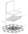
図1は、本発明の実施の形態1に係るメンブレンリフレクタの構成を説明するための分解斜視図であり、図2は、本発明の実施の形態1に係るメンブレンリフレクタの構成を説明するための模式断面図である。図1および2において、本実施の形態1に係るメンブレンリフレクタは、3軸織物からなり、反射面を有する多孔質鏡面部1と、多孔質鏡面部1の反射面の裏面(接着結合面)側に配置され、多孔質鏡面部1に接着剤4を介して接着結合された結合部品2とを備えている。結合部品2が接着接合される部分に対応した多孔質鏡面部1の少なくとも接着結合面、つまり、結合部品2の接着結合面直下の多孔質鏡面部1には、樹脂3を含浸させることで、多孔質鏡面部1の孔(空隙)を目止めしている。このように多孔質鏡面部1の孔(空隙)を目止めしておくことで、メンブレンリフレクタを製造する際に、多孔質鏡面部1と結合部品2とが接着結合されるべき部分に接着剤4を塗布しても多孔質鏡面部1の孔への接着剤4の浸透が防止されるため、多孔質鏡面部1において熱膨張差を生じ難くすることができる。
Hereinafter, the present invention will be described in detail.
Embodiment 1 FIG.
FIG. 1 is an exploded perspective view for explaining the configuration of the membrane reflector according to Embodiment 1 of the present invention, and FIG. 2 is for explaining the configuration of the membrane reflector according to Embodiment 1 of the present invention. It is a schematic cross section. 1 and 2, the membrane reflector according to the first embodiment is made of a triaxial woven fabric, and includes a porous mirror surface portion 1 having a reflection surface, and a back surface (adhesive bonding surface) side of the reflection surface of the porous mirror surface portion 1 And a
本発明における接着剤4としては、当該技術分野で公知のものを制限なく用いることができ、例えば、エポキシ系接着剤、アクリル系接着剤、シリコーン系接着剤等が挙げられる。また、本発明における樹脂3としては、接着剤4と熱膨張係数が同等であるかまたは接着剤4よりも熱膨張係数が小さいものが好ましい。接着剤4と樹脂3との好ましい組み合わせとしては、例えば、エポキシ系接着剤とエポキシ樹脂との組み合わせが挙げられる。また、含浸させる樹脂3の粘度は、加圧によって多孔質鏡面部1の孔に樹脂3を含浸させることができる程度であることが好ましく、好ましくは20N・s/m2〜80N・s/m2であり、最も好ましくは50N・s/m2(500ポイズ)程度である。
As the adhesive 4 in this invention, what is known in the said technical field can be used without a restriction | limiting, For example, an epoxy-type adhesive agent, an acrylic adhesive agent, a silicone type adhesive agent etc. are mentioned. In addition, as the
上記のように構成されたメンブレンリフレクタは、結合部品2の接着結合面直下の多孔質鏡面部1に樹脂3を含浸させることができるように、多孔質鏡面部1の結合部品2が接着結合される部分以外をマスキングし、次に、マスキングされていない部分に樹脂3を含浸させて多孔質鏡面部1の孔を目止めし、続いて、その目止めされた多孔質鏡面部1と結合部品2とを接着剤4を用いて接着結合することにより製造することができる。多孔質鏡面部1への樹脂3の含浸は、ボイド混入の回避という観点から、加圧により行うことが好ましい。
In the membrane reflector configured as described above, the
実施の形態1によれば、結合部品2との接着結合面周囲における多孔質鏡面部1の孔への接着剤4の浸透が防止されるため、メンブレンリフレクタの温度変化による鏡面精度の劣化を抑制することができる。
According to the first embodiment, since the penetration of the adhesive 4 into the hole of the porous mirror surface portion 1 around the adhesive bonding surface with the
なお、実施の形態1では、多孔質鏡面部1として、3軸織物を使用した場合について説明したが、2軸織物等の当該技術分野で公知のものを使用しても同様の効果を達成することができる。 In the first embodiment, the case where a triaxial woven fabric is used as the porous mirror surface portion 1 has been described. However, the same effect can be achieved even if a biaxial woven fabric or the like is used in the technical field. be able to.
1 多孔質鏡面部、2 結合部品、3 樹脂、4 接着剤。 1 porous mirror surface part, 2 bonded parts, 3 resin, 4 adhesive.
Claims (2)
前記結合部品が接着結合される部分に対応した前記多孔質鏡面部の少なくとも接着結合面側に、樹脂が含浸されていることを特徴とするメンブレンリフレクタ。 A membrane reflector comprising a porous mirror surface part and a bonding component bonded and bonded to the porous mirror surface part via an adhesive,
A membrane reflector, wherein a resin is impregnated on at least an adhesive bonding surface side of the porous mirror surface portion corresponding to a portion to which the bonding component is bonded and bonded.
前記多孔質鏡面部の前記結合部品が接着結合される部分以外をマスキングした後、マスキングされていない部分に樹脂を含浸させて多孔質鏡面部の孔を目止めし、次に、目止めされた多孔質鏡面部と結合部品とを前記接着剤を用いて接着結合することを特徴とするメンブレンリフレクタの製造方法。 A method for manufacturing a membrane reflector comprising a porous mirror surface portion and a bonded component bonded and bonded to the porous mirror surface portion via an adhesive,
After masking the part of the porous mirror surface part other than the part to be bonded and bonded, the non-masked part was impregnated with resin to seal the pores in the porous mirror surface part, and then sealed A method for manufacturing a membrane reflector, comprising: bonding a porous mirror surface part and a bonding component using the adhesive.
Priority Applications (1)
| Application Number | Priority Date | Filing Date | Title |
|---|---|---|---|
| JP2008176783A JP5004884B2 (en) | 2008-07-07 | 2008-07-07 | Membrane reflector and manufacturing method thereof |
Applications Claiming Priority (1)
| Application Number | Priority Date | Filing Date | Title |
|---|---|---|---|
| JP2008176783A JP5004884B2 (en) | 2008-07-07 | 2008-07-07 | Membrane reflector and manufacturing method thereof |
Publications (2)
| Publication Number | Publication Date |
|---|---|
| JP2010016747A true JP2010016747A (en) | 2010-01-21 |
| JP5004884B2 JP5004884B2 (en) | 2012-08-22 |
Family
ID=41702399
Family Applications (1)
| Application Number | Title | Priority Date | Filing Date |
|---|---|---|---|
| JP2008176783A Active JP5004884B2 (en) | 2008-07-07 | 2008-07-07 | Membrane reflector and manufacturing method thereof |
Country Status (1)
| Country | Link |
|---|---|
| JP (1) | JP5004884B2 (en) |
Cited By (1)
| Publication number | Priority date | Publication date | Assignee | Title |
|---|---|---|---|---|
| JPWO2013190823A1 (en) * | 2012-06-22 | 2016-02-08 | パナソニックIpマネジメント株式会社 | Solar cell module |
Citations (5)
| Publication number | Priority date | Publication date | Assignee | Title |
|---|---|---|---|---|
| JPH10270922A (en) * | 1997-03-24 | 1998-10-09 | Mitsubishi Electric Corp | Satellite-mount reflector |
| JP2000114861A (en) * | 1998-10-01 | 2000-04-21 | Mitsubishi Electric Corp | Structure of antenna reflector mounted on artificial satellite |
| JP2004146801A (en) * | 2002-10-03 | 2004-05-20 | Murata Mfg Co Ltd | Porous magnet, manufacturing method thereof, electric-wave absorber and magnet lens therewith |
| JP2005217696A (en) * | 2004-01-29 | 2005-08-11 | Mitsubishi Electric Corp | Membrane reflector and manufacturing method thereof |
| JP2006229750A (en) * | 2005-02-18 | 2006-08-31 | Mitsubishi Electric Corp | Unfolding antenna for space |
-
2008
- 2008-07-07 JP JP2008176783A patent/JP5004884B2/en active Active
Patent Citations (5)
| Publication number | Priority date | Publication date | Assignee | Title |
|---|---|---|---|---|
| JPH10270922A (en) * | 1997-03-24 | 1998-10-09 | Mitsubishi Electric Corp | Satellite-mount reflector |
| JP2000114861A (en) * | 1998-10-01 | 2000-04-21 | Mitsubishi Electric Corp | Structure of antenna reflector mounted on artificial satellite |
| JP2004146801A (en) * | 2002-10-03 | 2004-05-20 | Murata Mfg Co Ltd | Porous magnet, manufacturing method thereof, electric-wave absorber and magnet lens therewith |
| JP2005217696A (en) * | 2004-01-29 | 2005-08-11 | Mitsubishi Electric Corp | Membrane reflector and manufacturing method thereof |
| JP2006229750A (en) * | 2005-02-18 | 2006-08-31 | Mitsubishi Electric Corp | Unfolding antenna for space |
Cited By (1)
| Publication number | Priority date | Publication date | Assignee | Title |
|---|---|---|---|---|
| JPWO2013190823A1 (en) * | 2012-06-22 | 2016-02-08 | パナソニックIpマネジメント株式会社 | Solar cell module |
Also Published As
| Publication number | Publication date |
|---|---|
| JP5004884B2 (en) | 2012-08-22 |
Similar Documents
| Publication | Publication Date | Title |
|---|---|---|
| RU2594657C2 (en) | Securing membranes in sound-absorbing cellular structure | |
| CN107533837B (en) | Acoustic structure with multiple degrees of freedom | |
| CN110914505B (en) | Flexible acoustic honeycomb | |
| US8235171B2 (en) | System and method for noise suppression | |
| US10250987B2 (en) | Carbon fiber dome and manufacturing method for same | |
| JP2007270842A (en) | Method for reducing stress in turbine bucket and turbine blade | |
| CA2936290C (en) | Multilayer panel for soundproofing aircraft interiors | |
| US9073621B2 (en) | Aircraft comprising an insulation system for thermal and acoustic insulation | |
| CA2618106C (en) | Sound absorption element for means of transport, in particular for aircraft | |
| US20210023810A1 (en) | Structural panel with woven element core | |
| JP5004884B2 (en) | Membrane reflector and manufacturing method thereof | |
| US11505335B2 (en) | Damper for an object placed in a medium subjected to vibrations and corresponding damper system | |
| CA2421453C (en) | Wind tunnel testing | |
| JP6427407B2 (en) | Honeycomb structure | |
| Biggerstaff et al. | Damping performance of cocured composite laminates with embedded viscoelastic layers | |
| JP2010030587A (en) | Low shock frangible joint | |
| JP2009034985A (en) | Advanced grid structure | |
| JP2008068437A (en) | Honeycomb sandwich panel | |
| JP2008203542A (en) | Sound absorbing body | |
| ATE326594T1 (en) | SUPPORTING STRUCTURE FOR BUILDING CONSTRUCTION | |
| JP2008306567A (en) | Membrane reflector | |
| EP1197669A1 (en) | Insert intended for the fixing of a device and methods for realization and fixing of this insert | |
| CN110486169A (en) | A kind of acoustical panel and the sound lining with it | |
| JP7421163B2 (en) | Waterproof components and waterproof structure | |
| JP2010213198A (en) | Membrane reflector |
Legal Events
| Date | Code | Title | Description |
|---|---|---|---|
| A621 | Written request for application examination |
Free format text: JAPANESE INTERMEDIATE CODE: A621 Effective date: 20110524 |
|
| A977 | Report on retrieval |
Free format text: JAPANESE INTERMEDIATE CODE: A971007 Effective date: 20120412 |
|
| TRDD | Decision of grant or rejection written | ||
| A01 | Written decision to grant a patent or to grant a registration (utility model) |
Free format text: JAPANESE INTERMEDIATE CODE: A01 Effective date: 20120424 |
|
| A01 | Written decision to grant a patent or to grant a registration (utility model) |
Free format text: JAPANESE INTERMEDIATE CODE: A01 |
|
| A61 | First payment of annual fees (during grant procedure) |
Free format text: JAPANESE INTERMEDIATE CODE: A61 Effective date: 20120522 |
|
| FPAY | Renewal fee payment (event date is renewal date of database) |
Free format text: PAYMENT UNTIL: 20150601 Year of fee payment: 3 |
|
| R150 | Certificate of patent or registration of utility model |
Free format text: JAPANESE INTERMEDIATE CODE: R150 Ref document number: 5004884 Country of ref document: JP Free format text: JAPANESE INTERMEDIATE CODE: R150 |
|
| R250 | Receipt of annual fees |
Free format text: JAPANESE INTERMEDIATE CODE: R250 |
|
| R250 | Receipt of annual fees |
Free format text: JAPANESE INTERMEDIATE CODE: R250 |
|
| R250 | Receipt of annual fees |
Free format text: JAPANESE INTERMEDIATE CODE: R250 |
|
| R250 | Receipt of annual fees |
Free format text: JAPANESE INTERMEDIATE CODE: R250 |
|
| R250 | Receipt of annual fees |
Free format text: JAPANESE INTERMEDIATE CODE: R250 |
|
| R250 | Receipt of annual fees |
Free format text: JAPANESE INTERMEDIATE CODE: R250 |
|
| R250 | Receipt of annual fees |
Free format text: JAPANESE INTERMEDIATE CODE: R250 |
|
| R250 | Receipt of annual fees |
Free format text: JAPANESE INTERMEDIATE CODE: R250 |