JP2010016349A - Power module substrate, power module, and method of manufacturing power module substrate - Google Patents
Power module substrate, power module, and method of manufacturing power module substrate Download PDFInfo
- Publication number
- JP2010016349A JP2010016349A JP2009065033A JP2009065033A JP2010016349A JP 2010016349 A JP2010016349 A JP 2010016349A JP 2009065033 A JP2009065033 A JP 2009065033A JP 2009065033 A JP2009065033 A JP 2009065033A JP 2010016349 A JP2010016349 A JP 2010016349A
- Authority
- JP
- Japan
- Prior art keywords
- metal plate
- ceramic substrate
- power module
- substrate
- concentration
- Prior art date
- Legal status (The legal status is an assumption and is not a legal conclusion. Google has not performed a legal analysis and makes no representation as to the accuracy of the status listed.)
- Granted
Links
Images


Classifications
-
- H—ELECTRICITY
- H01—ELECTRIC ELEMENTS
- H01L—SEMICONDUCTOR DEVICES NOT COVERED BY CLASS H10
- H01L2224/00—Indexing scheme for arrangements for connecting or disconnecting semiconductor or solid-state bodies and methods related thereto as covered by H01L24/00
- H01L2224/01—Means for bonding being attached to, or being formed on, the surface to be connected, e.g. chip-to-package, die-attach, "first-level" interconnects; Manufacturing methods related thereto
- H01L2224/26—Layer connectors, e.g. plate connectors, solder or adhesive layers; Manufacturing methods related thereto
- H01L2224/31—Structure, shape, material or disposition of the layer connectors after the connecting process
- H01L2224/32—Structure, shape, material or disposition of the layer connectors after the connecting process of an individual layer connector
- H01L2224/321—Disposition
- H01L2224/32151—Disposition the layer connector connecting between a semiconductor or solid-state body and an item not being a semiconductor or solid-state body, e.g. chip-to-substrate, chip-to-passive
- H01L2224/32221—Disposition the layer connector connecting between a semiconductor or solid-state body and an item not being a semiconductor or solid-state body, e.g. chip-to-substrate, chip-to-passive the body and the item being stacked
- H01L2224/32225—Disposition the layer connector connecting between a semiconductor or solid-state body and an item not being a semiconductor or solid-state body, e.g. chip-to-substrate, chip-to-passive the body and the item being stacked the item being non-metallic, e.g. insulating substrate with or without metallisation
-
- H—ELECTRICITY
- H01—ELECTRIC ELEMENTS
- H01L—SEMICONDUCTOR DEVICES NOT COVERED BY CLASS H10
- H01L2924/00—Indexing scheme for arrangements or methods for connecting or disconnecting semiconductor or solid-state bodies as covered by H01L24/00
- H01L2924/013—Alloys
- H01L2924/0132—Binary Alloys
- H01L2924/01322—Eutectic Alloys, i.e. obtained by a liquid transforming into two solid phases
Abstract
Description
この発明は、大電流、高電圧を制御する半導体装置に用いられるパワーモジュール用基板、このパワーモジュール基板を備えたパワーモジュール及びこのパワーモジュール用基板の製造方法に関するものである。 The present invention relates to a power module substrate used in a semiconductor device that controls a large current and a high voltage, a power module including the power module substrate, and a method for manufacturing the power module substrate.
半導体素子の中でも電力供給のためのパワーモジュールは発熱量が比較的高いため、これを搭載する基板としては、例えば、AlN(窒化アルミ)からなるセラミックス基板上にAl(アルミニウム)の金属板がAl−Si系のろう材を介して接合されたパワーモジュール用基板が用いられる。
また、この金属板は回路層として形成され、その金属板の上には、はんだ材を介してパワー素子の半導体チップが搭載される。
なお、セラミックス基板の下面にも放熱のためにAl等の金属板が接合されて金属層とされ、この金属層を介して放熱板上にパワーモジュール用基板全体が接合されたものが提案されている。
A power module for supplying power among semiconductor elements has a relatively high calorific value. For example, an Al (aluminum) metal plate is formed on a ceramic substrate made of AlN (aluminum nitride). A power module substrate bonded via a Si-based brazing material is used.
The metal plate is formed as a circuit layer, and a power element semiconductor chip is mounted on the metal plate via a solder material.
In addition, a metal plate made of Al or the like is bonded to the lower surface of the ceramic substrate to form a metal layer for heat dissipation, and the entire power module substrate is bonded to the heat sink via this metal layer. Yes.
従来、前記回路層及び前記金属層としての金属板とセラミックス基板との良好な接合強度を得るため、例えば下記特許文献1に、セラミックス基板の表面粗さを0.5μm未満にしている技術が開示されている。 Conventionally, in order to obtain good bonding strength between the circuit layer and the metal plate as the metal layer and the ceramic substrate, for example, the following Patent Document 1 discloses a technique in which the surface roughness of the ceramic substrate is less than 0.5 μm. Has been.
しかしながら、金属板をセラミックス基板に接合する場合、単にセラミックス基板の表面粗さを低減しても十分に高い接合強度が得られず、信頼性の向上が図れないという不都合があった。例えば、セラミックス基板の表面に対して、乾式でAl2O3粒子によるホーニング処理を行い、表面粗さをRa=0.2μmにしても、剥離試験で界面剥離が生じてしまう場合があることが分かった。また、研磨法により表面粗さをRa=0.1μm以下にしても、やはり同様に界面剥離が生じてしまう場合があった。 However, when the metal plate is bonded to the ceramic substrate, there is a disadvantage that a sufficiently high bonding strength cannot be obtained even if the surface roughness of the ceramic substrate is simply reduced, and the reliability cannot be improved. For example, even if the surface of the ceramic substrate is subjected to a honing process with Al 2 O 3 particles in a dry manner and the surface roughness is set to Ra = 0.2 μm, interface peeling may occur in the peeling test. I understood. Further, even when the surface roughness was set to Ra = 0.1 μm or less by the polishing method, there was a case where the interface peeling occurred in the same manner.
特に、最近では、パワーモジュールの小型化・薄肉化が進められるとともに、その使用環境も厳しくなってきており、電子部品からの発熱量が大きくなる傾向にあり、前述のように放熱板上にパワーモジュール用基板を配設する必要がある。この場合、パワーモジュール用基板が放熱板によって拘束されるために、熱サイクル負荷時に、金属板とセラミックス基板との接合界面に大きなせん断力が作用することになるため、さらなる接合強度の向上及び信頼性の向上が求められている。 In particular, recently, power modules have become smaller and thinner, and the usage environment has become harsh, and the amount of heat generated from electronic components tends to increase. It is necessary to dispose a module substrate. In this case, since the power module substrate is constrained by the heat radiating plate, a large shearing force acts on the bonding interface between the metal plate and the ceramic substrate at the time of thermal cycle load. There is a need for improvement in performance.
この発明は、前述した事情に鑑みてなされたものであって、金属板とセラミックス基板とが確実に接合され、熱サイクル信頼性の高いパワーモジュール用基板、このパワーモジュール基板を備えたパワーモジュール及びこのパワーモジュール用基板の製造方法を提供することを目的とする。 The present invention has been made in view of the above-described circumstances, wherein a metal plate and a ceramic substrate are securely bonded to each other, and a power module substrate having high thermal cycle reliability, a power module including the power module substrate, and It aims at providing the manufacturing method of this board | substrate for power modules.
このような課題を解決して、前記目的を達成するために、本発明のパワーモジュール用基板は、セラミックス基板の表面に、アルミニウムからなる金属板が積層されて接合されたパワーモジュール用基板であって、前記金属板と前記セラミックス基板とがSiを含有するろう材を用いて接合されるとともに、前記金属板と前記セラミックス基板の接合界面にCuが添加されており、前記金属板には、Si及びCuが固溶しており、前記接合界面側部分におけるSi濃度が0.05〜0.5wt%,Cu濃度が0.05〜1.0wt%の範囲内に設定されていることを特徴としている。 In order to solve such problems and achieve the above object, the power module substrate of the present invention is a power module substrate in which a metal plate made of aluminum is laminated and bonded to the surface of a ceramic substrate. In addition, the metal plate and the ceramic substrate are bonded using a brazing material containing Si, and Cu is added to the bonding interface between the metal plate and the ceramic substrate. And Cu is solid-solved, and the Si concentration in the bonding interface side portion is set to 0.05 to 0.5 wt% and the Cu concentration is set to 0.05 to 1.0 wt%. Yes.
この構成のパワーモジュール用基板においては、セラミックス基板とアルミニウムからなる金属板とがSiを含有するろう材を用いて接合されるとともに、前記金属板と前記セラミックス基板の接合界面にCuが添加されている。ここで、Cuは、Alに対して反応性の高い元素であるため、接合界面にCuが存在することによってアルミニウムからなる金属板の表面が活性化することになる。よって、一般的なAl−Si系のろう材を用いて、比較的低温、短時間の接合条件で接合しても、セラミックス基板と金属板とを強固に接合することが可能となる。
なお、Cuを接合界面に添加する方法としては、セラミックス基板及びろう材の表面にCuを蒸着、スパッタリング及びメッキ等によって固着してもよいし、Al−Si系のろう材中にCuを含有させてもよい。
In the power module substrate having this configuration, the ceramic substrate and the metal plate made of aluminum are bonded using a brazing material containing Si, and Cu is added to the bonding interface between the metal plate and the ceramic substrate. Yes. Here, since Cu is an element having high reactivity with respect to Al, the presence of Cu at the bonding interface activates the surface of the metal plate made of aluminum. Therefore, it is possible to firmly bond the ceramic substrate and the metal plate even when bonding is performed using a general Al—Si brazing material under relatively low temperature and short time bonding conditions.
As a method for adding Cu to the bonding interface, Cu may be fixed to the surface of the ceramic substrate and the brazing material by vapor deposition, sputtering, plating or the like, or Cu may be contained in the Al-Si brazing material. May be.
また、前記金属板にCuが固溶しており、接合界面側部分のCu濃度が、0.05〜1.0wt%の範囲内に設定されているので、金属板の接合界面側部分が固溶強化することになる。これにより、金属板部分での破断を防止することができ、接合信頼性を向上させることができる。
さらに、セラミックス基板とアルミニウムからなる金属板とがSiを含有するろう材を用いて接合されており、前記金属板にSiが固溶し、接合界面側部分のSi濃度が、0.05〜0.5wt%の範囲内に設定されているので、ろう材が確実に溶融してSiが十分に金属板に拡散しており、セラミックス基板と金属板とが強固に接合される。
In addition, since Cu is solid-solved in the metal plate and the Cu concentration in the bonding interface side portion is set within a range of 0.05 to 1.0 wt%, the bonding interface side portion of the metal plate is solid. It will be strengthened. Thereby, the fracture | rupture in a metal plate part can be prevented and joining reliability can be improved.
Furthermore, the ceramic substrate and the metal plate made of aluminum are bonded using a brazing material containing Si, Si is solid-solved in the metal plate, and the Si concentration in the bonded interface side portion is 0.05 to 0. Since it is set within the range of 5 wt%, the brazing material is surely melted and Si is sufficiently diffused into the metal plate, and the ceramic substrate and the metal plate are firmly bonded.
また、前記セラミックス基板の幅が前記金属板の幅よりも広く設定されており、前記金属板の幅方向端部においては、アルミニウム中にSi,Cuが固溶されたアルミニウム相と、Siの含有率が98wt%以上とされたSi相と、AlとCuとSiの3元共晶組織からなる共晶相と、が形成されていることが好ましい。
この場合、金属板の幅方向端部に、アルミニウム中にSi,Cuが固溶されたアルミニウム相以外に、Siの含有率が98wt%以上とされたSi相と、AlとCuとSiの3元共晶組織からなる共晶相が形成されているので、金属板の幅方向端部を強化することが可能となる。
Further, the width of the ceramic substrate is set wider than the width of the metal plate, and at the end in the width direction of the metal plate, an aluminum phase in which Si and Cu are dissolved in aluminum, and the inclusion of Si It is preferable that a Si phase having a rate of 98 wt% or more and a eutectic phase composed of a ternary eutectic structure of Al, Cu, and Si are formed.
In this case, at the end in the width direction of the metal plate, in addition to the aluminum phase in which Si and Cu are dissolved in aluminum, the Si phase in which the Si content is 98 wt% or more, and Al, Cu and Si 3 Since the eutectic phase composed of the original eutectic structure is formed, it is possible to reinforce the width direction end of the metal plate.
さらに、前記共晶相においては、Cuを含む化合物からなる析出粒子が析出していることが好ましい。
この場合、金属板の幅方向端部に形成された共晶相において、Cuを含む化合物からなる析出粒子が析出しているので、金属板の幅方向端部を析出強化することが可能となる。これにより、金属板の幅方向端部からの破断の発生を防止することができ、接合信頼性を向上させることができる。
Further, in the eutectic phase, it is preferable that precipitated particles made of a compound containing Cu are precipitated.
In this case, in the eutectic phase formed at the end portion in the width direction of the metal plate, the precipitated particles made of the compound containing Cu are precipitated, so that the end portion in the width direction of the metal plate can be strengthened by precipitation. . Thereby, generation | occurrence | production of the fracture | rupture from the width direction edge part of a metal plate can be prevented, and joining reliability can be improved.
ここで、前記セラミックス基板がAlN又はAl2O3で構成されており、前記金属板と前記セラミックス基板との接合界面に、Si濃度が前記金属板中のSi濃度の5倍以上とされたSi高濃度部が形成されていてもよい。
この場合、前記金属板と前記セラミックス基板との接合界面に、Si濃度が前記金属板中のSi濃度の5倍以上とされたSi高濃度部が形成されているので、接合界面に存在するSi原子によってAlN又はAl2O3からなるセラミックス基板とアルミニウムからなる金属板との接合強度が向上することになる。なお、ここで、金属板中のSi濃度とは、金属板のうち接合界面から一定距離(例えば、50nm以上)離れた部分におけるSi濃度である。
Here, the ceramic substrate is made of AlN or Al 2 O 3 , and the Si concentration is 5 times or more of the Si concentration in the metal plate at the bonding interface between the metal plate and the ceramic substrate. A high concentration part may be formed.
In this case, since a Si high concentration portion in which the Si concentration is 5 times or more of the Si concentration in the metal plate is formed at the bonding interface between the metal plate and the ceramic substrate, Si present at the bonding interface is formed. The bonding strength between the ceramic substrate made of AlN or Al 2 O 3 and the metal plate made of aluminum is improved by the atoms. Here, the Si concentration in the metal plate is the Si concentration in a portion of the metal plate that is away from the bonding interface by a certain distance (for example, 50 nm or more).
接合界面に高濃度で存在するSiは、主にろう材中に含有されたSiであると考えられる。接合時に、Siはアルミニウム(金属板)中に拡散し、接合界面から減少することになるが、セラミックスとアルミニウム(金属板)との界面部分が不均一核生成のサイトとなってSi原子が界面部分に残存し、Si濃度が前記金属板中のSi濃度の5倍以上とされたSi高濃度部が形成されることになる。 Si present at a high concentration at the bonding interface is considered to be mainly Si contained in the brazing material. At the time of bonding, Si diffuses into the aluminum (metal plate) and decreases from the bonding interface, but the interface between the ceramic and aluminum (metal plate) serves as a site for heterogeneous nucleation, and Si atoms are interfaced. A high Si concentration portion that remains in the portion and has a Si concentration of 5 times or more the Si concentration in the metal plate is formed.
また、前記セラミックス基板がSi3N4で構成されており、前記金属板と前記セラミックス基板との接合界面に、酸素濃度が前記金属板中及び前記セラミックス基板中の酸素濃度よりも高くされた酸素高濃度部が形成されており、該酸素高濃度部の厚さが4nm以下とされていてもよい。
この場合、Si3N4からなるセラミックス基板とアルミニウムからなる金属板との接合界面に、酸素濃度が前記金属板中及び前記セラミックス基板中の酸素濃度よりも高くされた酸素高濃度部が形成されているので、接合界面に存在する酸素によってSi3N4からなるセラミックス基板とアルミニウムからなる金属板との接合強度が向上する。さらに、この酸素高濃度部の厚さが4nm以下とされているので、熱サイクルを負荷した際の応力によって酸素高濃度部にクラックが発生することが抑制される。
なお、ここで、金属板中及びセラミックス基板中の酸素濃度とは、金属板及びセラミックス基板のうち接合界面から一定距離(例えば、50nm以上)離れた部分における酸素濃度である。
The ceramic substrate is made of Si 3 N 4 , and an oxygen concentration is higher than an oxygen concentration in the metal plate and in the ceramic substrate at a bonding interface between the metal plate and the ceramic substrate. A high concentration part may be formed, and the thickness of the oxygen high concentration part may be 4 nm or less.
In this case, a high oxygen concentration portion in which the oxygen concentration is higher than the oxygen concentration in the metal plate and the ceramic substrate is formed at the bonding interface between the ceramic substrate made of Si 3 N 4 and the metal plate made of aluminum. Therefore, the bonding strength between the ceramic substrate made of Si 3 N 4 and the metal plate made of aluminum is improved by oxygen present at the bonding interface. Furthermore, since the thickness of the high oxygen concentration portion is 4 nm or less, the occurrence of cracks in the high oxygen concentration portion due to stress when a thermal cycle is applied is suppressed.
Here, the oxygen concentration in the metal plate and the ceramic substrate is an oxygen concentration in a portion of the metal plate and the ceramic substrate that is away from the bonding interface by a certain distance (for example, 50 nm or more).
また、接合界面に高濃度で存在する酸素は、セラミックス基板の表面に存在する酸素及びろう材の表面に形成された酸化膜から取り込まれたものであると考えられる。ここで、酸素濃度が接合界面において高濃度に存在するということは、これらの酸化膜等が確実に除去されるように十分に加熱されていることになり、セラミックス基板と金属板とを強固に接合することが可能となる。 Further, it is considered that oxygen present at a high concentration at the bonding interface is taken from oxygen present on the surface of the ceramic substrate and an oxide film formed on the surface of the brazing material. Here, the high oxygen concentration at the bonding interface means that the oxide film and the like are sufficiently heated so that the ceramic substrate and the metal plate are firmly removed. It becomes possible to join.
本発明のパワーモジュールは、前述のパワーモジュール用基板と、該パワーモジュール用基板上に搭載された電子部品と、を備えることを特徴としている。
この構成のパワーモジュールによれば、セラミックス基板と金属板との接合強度が高く、使用環境が厳しい場合であっても、その信頼性を飛躍的に向上させることができる。
A power module according to the present invention includes the power module substrate described above and an electronic component mounted on the power module substrate.
According to the power module having this configuration, the bonding strength between the ceramic substrate and the metal plate is high, and the reliability can be drastically improved even when the usage environment is severe.
また、本発明のパワーモジュール用基板の製造方法は、セラミックス基板の表面に、アルミニウムからなる金属板が積層されて接合されたパワーモジュール用基板の製造方法であって、前記セラミックス基板と前記金属板との間にSiを含有するろう材を介装させて積層させる積層工程と、積層された前記セラミックス基板と前記金属板を加圧した状態で加熱し、前記ろう材を溶融させてセラミックス基板及び金属板の界面に溶融アルミニウム層を形成する溶融工程と、前記溶融アルミニウム層を凝固させる凝固工程と、を有し、 前記積層工程の前に、前記セラミックス基板の接合面及び前記ろう材のセラミックス基板側の表面のうち少なくとも一方にCuを固着させるCu固着工程を有していることを特徴としている。 The method for manufacturing a power module substrate according to the present invention is a method for manufacturing a power module substrate in which a metal plate made of aluminum is laminated and bonded to the surface of the ceramic substrate, the ceramic substrate and the metal plate. A laminating step of interposing and laminating a brazing material containing Si, heating the laminated ceramic substrate and the metal plate in a pressurized state, melting the brazing material, A melting step of forming a molten aluminum layer at the interface of the metal plate; and a solidification step of solidifying the molten aluminum layer, and before the laminating step, the bonding surface of the ceramic substrate and the ceramic substrate of the brazing material A Cu fixing step of fixing Cu to at least one of the side surfaces is provided.
この構成のパワーモジュール用基板の製造方法によれば、前記セラミックス基板と前記金属板との間にSiを含有するろう材を介装させて積層させる積層工程の前に、前記セラミックス基板の接合面及び前記ろう材のセラミックス基板側の表面のうち少なくとも一方にCuを固着させるCu固着工程を有しているので、前記セラミックス基板と前記金属板との接合界面にCuが確実に添加され、このCuによって金属板の表面が活性化され、一般的なAl−Si系のろう材を用いて比較的低温、短時間の接合条件で接合しても、セラミックス基板と金属板とを強固に接合することが可能となる。 According to the method for manufacturing a power module substrate having this structure, the bonding surface of the ceramic substrate is placed before the laminating step of interposing and laminating the brazing material containing Si between the ceramic substrate and the metal plate. And a Cu fixing step for fixing Cu to at least one of the surfaces of the brazing material on the ceramic substrate side, Cu is surely added to the bonding interface between the ceramic substrate and the metal plate. The surface of the metal plate is activated by this, and the ceramic substrate and the metal plate can be firmly bonded even when bonded using a general Al-Si brazing material under relatively low temperature and short time bonding conditions. Is possible.
ここで、前記Cu固着工程を、蒸着又はスパッタリングによって前記セラミックス基板の接合面及び前記ろう材の表面の少なくとも一方にCuを固着させるものとすることが好ましい。
この場合、蒸着又はスパッタリングによって、Cuが前記セラミックス基板の接合面及び前記ろう材の表面の少なくとも一方に確実に固着され、セラミックス基板と金属板との接合界面にCuを確実に存在させることが可能となる。これにより、Cuによって金属板の表面が活性化され、セラミックス基板と金属板とを強固に接合することが可能となる。
Here, it is preferable that the Cu fixing step fix Cu to at least one of the bonding surface of the ceramic substrate and the surface of the brazing material by vapor deposition or sputtering.
In this case, Cu can be securely fixed to at least one of the bonding surface of the ceramic substrate and the surface of the brazing material by vapor deposition or sputtering, and Cu can be surely present at the bonding interface between the ceramic substrate and the metal plate. It becomes. Thereby, the surface of the metal plate is activated by Cu, and the ceramic substrate and the metal plate can be firmly bonded.
本発明によれば、金属板とセラミックス基板とが確実に接合され、熱サイクル信頼性の高いパワーモジュール用基板、このパワーモジュール基板を備えたパワーモジュール及びこのパワーモジュール用基板の製造方法を提供することが可能となる。 According to the present invention, there are provided a power module substrate having a high thermal cycle reliability in which a metal plate and a ceramic substrate are reliably bonded, a power module including the power module substrate, and a method for manufacturing the power module substrate. It becomes possible.
以下に、本発明の実施形態について添付した図面を参照して説明する。図1に本発明の第1の実施形態であるパワーモジュール用基板及びパワーモジュールを示す。
このパワーモジュール1は、回路層12が配設されたパワーモジュール用基板10と、回路層12の表面にはんだ層2を介して接合された半導体チップ3と、ヒートシンク4とを備えている。ここで、はんだ層2は、例えばSn−Ag系、Sn−In系、若しくはSn−Ag−Cu系のはんだ材とされている。なお、本実施形態では、回路層12とはんだ層2との間にNiメッキ層(図示なし)が設けられている。
Embodiments of the present invention will be described below with reference to the accompanying drawings. FIG. 1 shows a power module substrate and a power module according to the first embodiment of the present invention.
The power module 1 includes a
パワーモジュール用基板10は、セラミックス基板11と、このセラミックス基板11の一方の面(図1において上面)に配設された回路層12と、セラミックス基板11の他方の面(図1において下面)に配設された金属層13とを備えている。
セラミックス基板11は、回路層12と金属層13との間の電気的接続を防止するものであって、絶縁性の高いAlN(窒化アルミ)で構成されている。また、セラミックス基板11の厚さは、0.2〜1.5mmの範囲内に設定されており、本実施形態では、0.635mmに設定されている。なお、本実施形態では、図1に示すように、セラミック基板11の幅は、回路層12及び金属層13の幅より広く設定されている。
The
The
回路層12は、セラミックス基板11の一方の面に導電性を有する金属板22が接合されることにより形成されている。本実施形態においては、回路層12は、純度が99.99%以上のアルミニウム(いわゆる4Nアルミニウム)の圧延板からなる金属板22がセラミックス基板11に接合されることにより形成されている。ここで、セラミックス基板11と金属板22の接合には、融点降下元素であるSiを含有したAl−Si系のろう材を用いている。
The
金属層13は、セラミックス基板11の他方の面に金属板23が接合されることにより形成されている。本実施形態においては、金属層13は、回路層12と同様に、純度が99.99%以上のアルミニウム(いわゆる4Nアルミニウム)の圧延板からなる金属板23がセラミックス基板11に接合されることで形成されている。ここで、セラミックス基板11と金属板23の接合には、融点降下元素であるSiを含有したAl−Si系のろう材を用いている。
The
ヒートシンク4は、前述のパワーモジュール用基板10を冷却するためのものであり、パワーモジュール用基板10と接合される天板部5と冷却媒体(例えば冷却水)を流通するための流路6とを備えている。ヒートシンク4(天板部5)は、熱伝導性が良好な材質で構成されることが望ましく、本実施形態においては、A6063(アルミニウム合金)で構成されている。
また、本実施形態においては、ヒートシンク4の天板部5と金属層13との間には、アルミニウム又はアルミニウム合金若しくはアルミニウムを含む複合材(例えばAlSiC等)からなる緩衝層15が設けられている。
The heat sink 4 is for cooling the
In the present embodiment, a
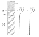
そして、図2に示すように、セラミックス基板11と回路層12(金属板22)及び金属層13(金属板23)との接合界面30の幅方向中央部(図1のA部)においては、回路層12(金属板22)及び金属層13(金属板23)にSi,Cuが固溶しており、接合界面30から積層方向に離間するにしたがい漸次Si,Cuの濃度が低下する濃度傾斜層33が形成されている。ここで、この濃度傾斜層33の接合界面30側のSi濃度が0.05〜0.5wt%,Cu濃度が0.05〜1.0wt%の範囲内に設定されている。
なお、濃度傾斜層33の接合界面30側のSi濃度及びCu濃度は、EPMA分析(スポット径30μm)で、接合界面30から50μmまでの範囲内を5点測定した平均値である。
As shown in FIG. 2, in the center part in the width direction (part A in FIG. 1) of the
Note that the Si concentration and the Cu concentration on the
また、セラミックス基板11と回路層12(金属板22)及び金属層13(金属板23)との接合界面30の幅方向端部35(図1のB部)においては、図3に示すように、アルミニウム中にSi,Cuが固溶したアルミニウム相41と、Siの含有率が98wt%以上とされたSi相42と、AlとCuとSiの3元共晶組織からなる共晶相43と、が形成されている。また、共晶相43内においては、Cuを含む化合物(例えばCuAl2)からなる析出物粒子が析出している。
Further, in the width direction end portion 35 (B portion in FIG. 1) of the
また、セラミックス基板11と回路層12(金属板22)及び金属層13(金属板23)との接合界面30を透過電子顕微鏡において観察した場合には、図4に示すように、接合界面30にSiが濃縮したSi高濃度部32が形成されている。このSi高濃度部32においては、Si濃度が、回路層12(金属板22)及び金属層13(金属板23)中のSi濃度よりも5倍以上高くなっている。なお、このSi高濃度部32の厚さHは4nm以下とされている。
ここで、観察する接合界面30は、図4に示すように、回路層12(金属板22)及び金属層13(金属板23)の格子像の界面側端部とセラミックス基板11の格子像の界面側端部との間の中央を基準面Sとする。
When the
Here, as shown in FIG. 4, the
このようなパワーモジュール用基板10は、以下のようにして製造される。
AlNからなるセラミックス基板11の両面に、スパッタリングによってCuが固着される(Cu固着工程)。
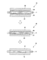
そして、図5に示すように、セラミックス基板11の一方の面に、回路層12となる金属板22(4Nアルミニウムの圧延板)が、厚さ10〜30μm(本実施形態では20μm)のろう材箔24を介して積層され、セラミックス基板11の他方の面に金属層13となる金属板23(4Nアルミニウムの圧延板)が厚さ10〜30μm(本実施形態では20μm)のろう材箔25を介して積層される(積層工程)。
Such a
Cu is fixed to both surfaces of the
And as shown in FIG. 5, the metal plate 22 (4N aluminum rolling plate) used as the
このようにして形成された積層体20をその積層方向に加圧(圧力1〜5kgf/cm2)した状態で真空炉内に装入して加熱し、ろう材箔24、25を溶融する(溶融工程)。ここで真空炉内の真空度は、10−3Pa〜10−5Paとされている。この溶融工程によって、図6に示すように、回路層12及び金属層13となる金属板22、23の一部とろう材箔24、25とが溶融し、セラミックス基板11の表面に溶融アルミニウム層26、27が形成される。
次に、積層体20を冷却することによって溶融アルミニウム層26、27を凝固させる(凝固工程)。
このようにして、回路層12及び金属層13となる金属板22、23とセラミックス基板11とが接合され、本実施形態であるパワーモジュール用基板10が製造される。
The
Next, the
In this way, the
以上のような構成とされた本実施形態であるパワーモジュール用基板10及びパワーモジュール1においては、セラミックス基板11と回路層12(金属板22)及び金属層13(金属板23)とが、Al−Si系のろう材を用いて接合されるとともに、回路層12(金属板22)及び金属層13(金属板23)とセラミックス基板11の接合界面30にCuが添加されているので、接合界面30に存在するCuとAlとが溶融反応し、比較的低温、短時間の接合条件で接合しても、セラミックス基板11と回路層12(金属板22)及び金属層13(金属板23)とを強固に接合でき、接合信頼性を大幅に向上させることができる。
In the
また、セラミックス基板11と回路層12(金属板22)及び金属層13(金属板23)との接合界面30の幅方向中央部(図1のA部)においては、回路層12(金属板22)及び金属層13(金属板23)にSi,Cuが固溶しており、接合界面30から積層方向に離間するにしたがい漸次Si,Cuの濃度が低下する濃度傾斜層33が形成されており、この濃度傾斜層33の接合界面30側のCu濃度が0.05〜1.0wt%の範囲内に設定されているので、回路層12(金属板22)及び金属層13(金属板23)の接合界面30側の部分が固溶強化し、回路層12(金属板22)及び金属層13(金属板23)における破断の発生を防止することができる。
また、この濃度傾斜層33の接合界面30側のSi濃度が0.05〜0.5wt%の範囲内に設定されているので、Siが十分に回路層12(金属板22)及び金属層13(金属板23)中に拡散しており、ろう材が確実に溶融して凝固されることでセラミックス基板11と回路層12(金属板22)及び金属層13(金属板23)とを強固に接合することができる。
The circuit layer 12 (metal plate 22) is formed at the central portion (A portion in FIG. 1) of the
In addition, since the Si concentration on the
さらに、セラミックス基板11の幅が回路層12(金属板22)及び金属層13(金属板23)の幅よりも広く設定され、回路層12(金属板22)及び金属層13(金属板23)の幅方向端部35に、アルミニウム中にSi,Cuが固溶したアルミニウム相41と、Siの含有率が98wt%以上とされたSi相42と、AlとCuとSiの3元共晶組織からなる共晶相43と、が形成されているので、回路層12(金属板22)及び金属層13(金属板23)の幅方向端部35の強度が向上することになる。さらに、共晶相43内においては、Cuを含む化合物(例えばCuAl2)からなる析出物粒子が析出しているので、幅方向端部35を析出強化することができる。
これにより、回路層12(金属板22)及び金属層13(金属板23)の幅方向端部35からの破断の発生を防止することができる。
Further, the width of the
Thereby, generation | occurrence | production of the fracture | rupture from the width
また、本実施形態では、セラミックス基板11がAlNで構成されており、金属板22、23とセラミックス基板11との接合界面30に、Si濃度が、回路層12(金属板22)及び金属層13(金属板23)中のSi濃度の5倍以上とされたSi高濃度部32が形成されているので、接合界面30に存在するSiによってセラミックス基板11と金属板22、23との接合強度の向上を図ることができる。
In this embodiment, the
次に、本発明の第2の実施形態について図7及び図8を参照して説明する。なお、第1の実施形態と同一の部材には同じ符号を付して詳細な説明を省略する。
この第2の実施形態であるパワーモジュール用基板110においては、セラミックス基板111がSi3N4で構成されている点が第1の実施形態と異なっている。
Next, a second embodiment of the present invention will be described with reference to FIGS. In addition, the same code | symbol is attached | subjected to the member same as 1st Embodiment, and detailed description is abbreviate | omitted.
The
ここで、セラミックス基板111と回路層12(金属板22)及び金属層13(金属板23)との接合界面30を透過電子顕微鏡において観察した場合には、図8に示すように、接合界面30に酸素が濃縮した酸素高濃度部132が形成されている。この酸素高濃度部132においては、酸素濃度が、回路層12(金属板22)及び金属層13(金属板23)中の酸素濃度よりも高くなっている。なお、この酸素高濃度部132の厚さHは4nm以下とされている。
なお、ここで観察する接合界面30は、図8に示すように、回路層12(金属板22)及び金属層13(金属板23)の格子像の界面側端部とセラミックス基板111の格子像の接合界面側端部との間の中央を基準面Sとする。
Here, when the
As shown in FIG. 8, the
以上のような構成とされた第2の本実施形態であるパワーモジュール用基板110においては、回路層12及び金属層13となる金属板22、23とセラミックス基板111との接合界面30に、酸素濃度が回路層12及び金属層13を構成する金属板22、23中の酸素濃度よりも高くされた酸素高濃度部132が生成されているので、この酸素によってセラミックス基板111と金属板22、23との接合強度の向上を図ることができる。また、この酸素高濃度部132の厚さが4nm以下とされているので、熱サイクルを負荷した際の応力によって酸素高濃度部132にクラックが発生することが抑制される。
In the
以上、本発明の実施形態について説明したが、本発明はこれに限定されることはなく、その発明の技術的思想を逸脱しない範囲で適宜変更可能である。
例えば、回路層及び金属層を構成する金属板を純度99.99%の純アルミニウムの圧延板としたものとして説明したが、これに限定されることはなく、純度99%のアルミニウム(2Nアルミニウム)であってもよい。
As mentioned above, although embodiment of this invention was described, this invention is not limited to this, It can change suitably in the range which does not deviate from the technical idea of the invention.
For example, the metal plate constituting the circuit layer and the metal layer has been described as a rolled plate of pure aluminum having a purity of 99.99%, but is not limited to this, and aluminum having a purity of 99% (2N aluminum) It may be.
また、ヒートシンクの天板部と金属層との間に、アルミニウム又はアルミニウム合金若しくはアルミニウムを含む複合材(例えばAlSiC等)からなる緩衝層を設けたものとして説明したが、この緩衝層がなくてもよい。
さらに、ヒートシンクをアルミニウムで構成したものとして説明したが、アルミニウム合金、又はアルミニウムを含む複合材等で構成されていてもよい。さらに、ヒートシンクとして冷却媒体の流路を有するもので説明したが、ヒートシンクの構造に特に限定はない。
Moreover, although demonstrated as what provided the buffer layer which consists of aluminum, the aluminum alloy, or the composite material containing aluminum (for example, AlSiC etc.) between the top-plate part of a heat sink and a metal layer, even if this buffer layer is not provided Good.
Furthermore, although the heat sink has been described as being made of aluminum, it may be made of an aluminum alloy or a composite material containing aluminum. Further, although the description has been given of the heat sink having a cooling medium flow path, the structure of the heat sink is not particularly limited.
また、第1の実施形態において、セラミックス基板をAlNで構成されたものとして説明したが、これに限定されることはなく、Al2O3等の他のセラミックスで構成されていてもよい。 In the first embodiment, the ceramic substrate is described as being made of AlN. However, the ceramic substrate is not limited to this, and may be made of other ceramics such as Al 2 O 3 .
また、セラミックス基板の表面にCuを固着させるCu固着工程を有したものとして説明したが、これに限定されることはなく、ろう材箔の表面にCuを固着させてもよい。また、スパッタでなく蒸着やメッキ等でCuを固着させてもよい。さらには、Al−Si系のろう材中にCuを添加してもよい。 Moreover, although it demonstrated as having the Cu adhering process which adheres Cu to the surface of a ceramic substrate, it is not limited to this, You may adhere Cu to the surface of a brazing material foil. Further, Cu may be fixed not by sputtering but by vapor deposition or plating. Further, Cu may be added to the Al—Si brazing material.
本発明の有効性を確認するために行った比較実験について説明する。
図9に示すように、比較例及び実施例1においては、厚さ0.635mmのAlNからなるセラミックス基板11と、厚さ0.6mmの4Nアルミニウムからなる回路層12と、厚さ0.6mmの4Nアルミニウムからなる金属層13と、厚さ5mmのアルミニウム合金(A6063)からなる天板部5と、厚さ1.0mmの4Nアルミニウムからなる緩衝層15とを共通に有している。
A comparative experiment conducted to confirm the effectiveness of the present invention will be described.
As shown in FIG. 9, in the comparative example and Example 1, the
実施例1は、セラミックス基板11の表面にCuをスパッタリングによって固着させた後に、回路層12及び金属層13となる金属板をAl−Si系ろう材を用いて接合した。
比較例は、Cuを接合界面に添加することなく、セラミックス基板11と回路層12及び金属層13となる金属板をAl−Si系ろう材を用いて接合した。
これらの試験片を用いて接合信頼性の評価を行った。接合信頼性の評価としては、熱サイクル(−45℃−125℃)を繰り返した後の接合率を比較した。評価結果を表1に示す。
In Example 1, after Cu was fixed to the surface of the
In the comparative example, the
These test pieces were used to evaluate the bonding reliability. As evaluation of joining reliability, the joining rate after repeating a thermal cycle (-45 degreeC-125 degreeC) was compared. The evaluation results are shown in Table 1.

接合界面にCuが添加されておらず、Al−Si系のろう材を用いて接合された比較例においては、熱サイクルを1000回負荷した時点では接合率が100%近くであったが2000回負荷した時点では接合率の低下が認められ、3000回負荷した時点では91.5%まで低下している。
一方、接合界面に、Cuが添加された実施例1においては、2000回負荷しても接合率は低下せず、3000回負荷後でも接合率は99.2%であった。
この確認実験により、本発明によれば、接合界面にCuを添加することによって、熱サイクル信頼性が向上することが確認された。
In the comparative example in which Cu was not added to the bonding interface and bonded using an Al—Si based brazing material, the bonding rate was close to 100% when the thermal cycle was loaded 1000 times, but 2000 times When the load is applied, a decrease in the bonding rate is recognized, and when the load is applied 3000 times, the reduction is 91.5%.
On the other hand, in Example 1 in which Cu was added to the bonding interface, the bonding rate did not decrease even after 2000 loading, and the bonding rate was 99.2% even after 3000 loading.
From this confirmation experiment, according to the present invention, it was confirmed that the thermal cycle reliability is improved by adding Cu to the bonding interface.
次に、パワーモジュール用基板における金属層の成分分析結果を示す。
厚さ0.635mmのAlNからなるセラミックス基板11に、厚さ0.6mmの4Nアルミニウムからなる回路層12と、厚さ0.6mmの4Nアルミニウムからなる金属層13とを接合し、パワーモジュール用基板を作製した。
ここで、実施例2−4は、Al―7.5wt%Siろう材の表面に1.5μm厚さのCu層を形成し、このAl―7.5wt%Siろう材を用いて、セラミックス基板11に回路層12と金属層13とを接合した。なお、接合温度を610℃、630℃、650℃の3水準とした。
実施例5−7は、セラミックス基板11の表面に1.5μm厚さのCu層を形成し、Al―7.5wt%Siろう材を用いて、セラミックス基板11に回路層12と金属層13とを接合した。なお、接合温度を610℃、630℃、650℃の3水準とした。
Next, the component analysis result of the metal layer in the power module substrate is shown.
For a power module, a
Here, in Example 2-4, a Cu layer having a thickness of 1.5 μm is formed on the surface of an Al-7.5 wt% Si brazing material, and this Al-7.5 wt% Si brazing material is used to form a ceramic substrate. 11, the
In Example 5-7, a 1.5 μm-thick Cu layer is formed on the surface of the
これら実施例2−7について、金属層とセラミックス基板との界面の幅方向中央部、前記界面の幅方向端部におけるCu濃度及びSi濃度をEPMAを用いて定量分析した。結果を表2に示す。 About these Examples 2-7, the Cu concentration and Si concentration in the width direction center part of the interface of a metal layer and a ceramic substrate and the width direction edge part of the said interface were quantitatively analyzed using EPMA. The results are shown in Table 2.
この定量分析の結果、セラミックス基板と金属板とを、Cu層を形成するとともにAl−Si系ろう材を用いて接合することにより、幅方向中央部においては、接合界面側部分におけるSi濃度が0.05〜0.5wt%,Cu濃度が0.05〜1.0wt%の範囲内に設定されることが確認された。また、幅方向端部においては、Si及びCuが高濃度に存在していることが確認された。 As a result of this quantitative analysis, the ceramic substrate and the metal plate are bonded together by forming a Cu layer and using an Al—Si brazing material, so that the Si concentration at the bonding interface side portion is 0 at the central portion in the width direction. 0.05 to 0.5 wt%, and the Cu concentration was confirmed to be set within the range of 0.05 to 1.0 wt%. Moreover, it was confirmed that Si and Cu exist in high concentration at the end in the width direction.
1,101 パワーモジュール
2 半導体チップ(電子部品)
10,110 パワーモジュール用基板
11、111 セラミックス基板
12 回路層
13 金属層
22、23 金属板
24、25 ろう材箔(ろう材)
26、27 溶融アルミニウム層
30 接合界面
32 Si高濃度部
132 酸素高濃度部
1,101
10, 110
26, 27
Claims (8)
前記金属板と前記セラミックス基板とがSiを含有するろう材を用いて接合されるとともに、前記金属板と前記セラミックス基板の接合界面にCuが添加されており、
前記金属板には、Si及びCuが固溶しており、前記接合界面側部分におけるSi濃度が0.05〜0.5wt%,Cu濃度が0.05〜1.0wt%の範囲内に設定されていることを特徴とするパワーモジュール用基板。 A power module substrate in which a metal plate made of aluminum is laminated and bonded to the surface of a ceramic substrate,
The metal plate and the ceramic substrate are bonded using a brazing material containing Si, and Cu is added to the bonding interface between the metal plate and the ceramic substrate,
Si and Cu are solid-dissolved in the metal plate, and the Si concentration in the bonding interface side portion is set within a range of 0.05 to 0.5 wt% and the Cu concentration is set within a range of 0.05 to 1.0 wt% A power module substrate, characterized in that
前記セラミックス基板と前記金属板との間にSiを含有するろう材を介装させて積層させる積層工程と、積層された前記セラミックス基板と前記金属板を加圧した状態で加熱し、前記ろう材を溶融させてセラミックス基板及び金属板の界面に溶融アルミニウム層を形成する溶融工程と、前記溶融アルミニウム層を凝固させる凝固工程と、を有し、
前記積層工程の前に、前記セラミックス基板の接合面及び前記ろう材のセラミックス基板側の表面のうち少なくとも一方にCuを固着させるCu固着工程を有していることを特徴とするパワーモジュール用基板の製造方法。 A method for manufacturing a power module substrate in which a metal plate made of aluminum is laminated and bonded to the surface of a ceramic substrate,
A laminating step of interposing and laminating a brazing material containing Si between the ceramic substrate and the metal plate; and heating the brazed material in a state where the laminated ceramic substrate and the metal plate are pressurized. And a melting step of forming a molten aluminum layer at the interface between the ceramic substrate and the metal plate, and a solidification step of solidifying the molten aluminum layer,
A power module substrate comprising a Cu fixing step of fixing Cu to at least one of a bonding surface of the ceramic substrate and a surface of the brazing material on the ceramic substrate side before the laminating step. Production method.
Priority Applications (8)
| Application Number | Priority Date | Filing Date | Title |
|---|---|---|---|
| JP2009065033A JP5423076B2 (en) | 2008-06-06 | 2009-03-17 | Power module substrate, power module, and method of manufacturing power module substrate |
| KR20107026985A KR20110033117A (en) | 2008-06-06 | 2009-06-05 | Substrate for power module, power module, and method for producing substrate for power module |
| PCT/JP2009/060392 WO2009148168A1 (en) | 2008-06-06 | 2009-06-05 | Substrate for power module, power module, and method for producing substrate for power module |
| EP09758435.3A EP2296177B1 (en) | 2008-06-06 | 2009-06-05 | Method for manufacturing a power module substrate |
| CN200980120627.8A CN102047413B (en) | 2008-06-06 | 2009-06-05 | Substrate for power module, power module, and method for producing substrate for power module |
| US12/737,042 US8564118B2 (en) | 2008-06-06 | 2009-06-05 | Power module substrate, power module, and method for manufacturing power module substrate |
| US14/027,601 US8921996B2 (en) | 2008-06-06 | 2013-09-16 | Power module substrate, power module, and method for manufacturing power module substrate |
| US14/511,610 US20150022977A1 (en) | 2008-06-06 | 2014-10-10 | Power module substrate, power module, and method for manufacturing power module substrate |
Applications Claiming Priority (3)
| Application Number | Priority Date | Filing Date | Title |
|---|---|---|---|
| JP2008149902 | 2008-06-06 | ||
| JP2008149902 | 2008-06-06 | ||
| JP2009065033A JP5423076B2 (en) | 2008-06-06 | 2009-03-17 | Power module substrate, power module, and method of manufacturing power module substrate |
Publications (2)
| Publication Number | Publication Date |
|---|---|
| JP2010016349A true JP2010016349A (en) | 2010-01-21 |
| JP5423076B2 JP5423076B2 (en) | 2014-02-19 |
Family
ID=41702122
Family Applications (1)
| Application Number | Title | Priority Date | Filing Date |
|---|---|---|---|
| JP2009065033A Active JP5423076B2 (en) | 2008-06-06 | 2009-03-17 | Power module substrate, power module, and method of manufacturing power module substrate |
Country Status (1)
| Country | Link |
|---|---|
| JP (1) | JP5423076B2 (en) |
Cited By (7)
| Publication number | Priority date | Publication date | Assignee | Title |
|---|---|---|---|---|
| JP2014090144A (en) * | 2012-10-31 | 2014-05-15 | Denki Kagaku Kogyo Kk | Ceramic circuit board, and method of manufacturing the same |
| US20140318831A1 (en) * | 2011-12-12 | 2014-10-30 | Mitsubishi Materials Corporation | Power module substrate, power module substrate with heat sink, power module, paste for forming flux component intrusion-preventing layer and method for bonding bonded body |
| CN104961468A (en) * | 2015-07-08 | 2015-10-07 | 长沙鼎成新材料科技有限公司 | TiAlN ceramic substrate for LED (light emitting diode) |
| CN105039820A (en) * | 2015-07-29 | 2015-11-11 | 长沙鼎成新材料科技有限公司 | Aluminum-silicon carbide ceramic substrate for LED |
| KR101795812B1 (en) * | 2009-09-09 | 2017-11-08 | 미쓰비시 마테리알 가부시키가이샤 | Substrate for power module, substrate for power module equiptted with heat sink, power module, and manufacturing method of substrate for power module |
| JP2020145369A (en) * | 2019-03-08 | 2020-09-10 | 三菱マテリアル株式会社 | Insulation circuit board and manufacturing method thereof |
| WO2020196528A1 (en) * | 2019-03-25 | 2020-10-01 | 京セラ株式会社 | Circuit substrate and heat dissipation substrate or electronic device provided with same |
Citations (4)
| Publication number | Priority date | Publication date | Assignee | Title |
|---|---|---|---|---|
| JPH08255973A (en) * | 1995-03-17 | 1996-10-01 | Toshiba Corp | Ceramic circuit board |
| JP2001010874A (en) * | 1999-03-27 | 2001-01-16 | Nippon Hybrid Technologies Kk | Production of composite material of inorganic material with metal containing aluminum and product related to the same |
| JP2001085808A (en) * | 1999-05-28 | 2001-03-30 | Denki Kagaku Kogyo Kk | Circuit board |
| JP2004356502A (en) * | 2003-05-30 | 2004-12-16 | Dowa Mining Co Ltd | Metal-ceramic circuit board and its manufacturing method |
-
2009
- 2009-03-17 JP JP2009065033A patent/JP5423076B2/en active Active
Patent Citations (4)
| Publication number | Priority date | Publication date | Assignee | Title |
|---|---|---|---|---|
| JPH08255973A (en) * | 1995-03-17 | 1996-10-01 | Toshiba Corp | Ceramic circuit board |
| JP2001010874A (en) * | 1999-03-27 | 2001-01-16 | Nippon Hybrid Technologies Kk | Production of composite material of inorganic material with metal containing aluminum and product related to the same |
| JP2001085808A (en) * | 1999-05-28 | 2001-03-30 | Denki Kagaku Kogyo Kk | Circuit board |
| JP2004356502A (en) * | 2003-05-30 | 2004-12-16 | Dowa Mining Co Ltd | Metal-ceramic circuit board and its manufacturing method |
Cited By (10)
| Publication number | Priority date | Publication date | Assignee | Title |
|---|---|---|---|---|
| KR101795812B1 (en) * | 2009-09-09 | 2017-11-08 | 미쓰비시 마테리알 가부시키가이샤 | Substrate for power module, substrate for power module equiptted with heat sink, power module, and manufacturing method of substrate for power module |
| US20140318831A1 (en) * | 2011-12-12 | 2014-10-30 | Mitsubishi Materials Corporation | Power module substrate, power module substrate with heat sink, power module, paste for forming flux component intrusion-preventing layer and method for bonding bonded body |
| JP2014090144A (en) * | 2012-10-31 | 2014-05-15 | Denki Kagaku Kogyo Kk | Ceramic circuit board, and method of manufacturing the same |
| CN104961468A (en) * | 2015-07-08 | 2015-10-07 | 长沙鼎成新材料科技有限公司 | TiAlN ceramic substrate for LED (light emitting diode) |
| CN105039820A (en) * | 2015-07-29 | 2015-11-11 | 长沙鼎成新材料科技有限公司 | Aluminum-silicon carbide ceramic substrate for LED |
| JP2020145369A (en) * | 2019-03-08 | 2020-09-10 | 三菱マテリアル株式会社 | Insulation circuit board and manufacturing method thereof |
| JP7272018B2 (en) | 2019-03-08 | 2023-05-12 | 三菱マテリアル株式会社 | Manufacturing method of insulated circuit board |
| WO2020196528A1 (en) * | 2019-03-25 | 2020-10-01 | 京セラ株式会社 | Circuit substrate and heat dissipation substrate or electronic device provided with same |
| JPWO2020196528A1 (en) * | 2019-03-25 | 2020-10-01 | ||
| JP7122461B2 (en) | 2019-03-25 | 2022-08-19 | 京セラ株式会社 | Circuit board and heat dissipation board or electronic device provided with the same |
Also Published As
| Publication number | Publication date |
|---|---|
| JP5423076B2 (en) | 2014-02-19 |
Similar Documents
| Publication | Publication Date | Title |
|---|---|---|
| WO2009148168A1 (en) | Substrate for power module, power module, and method for producing substrate for power module | |
| KR102097177B1 (en) | Power module substrate, power module substrate with heat sink, and power module | |
| JP6696214B2 (en) | Bonded body, power module substrate with heat sink, heat sink, and method of manufacturing bonded body, method of manufacturing power module substrate with heat sink, and method of manufacturing heat sink | |
| JP5423076B2 (en) | Power module substrate, power module, and method of manufacturing power module substrate | |
| WO2009139472A1 (en) | Substrate for power module, power module, and method for producing substrate for power module | |
| JP5359954B2 (en) | Power module substrate with heat sink, power module, and method for manufacturing power module substrate with heat sink | |
| JP5504842B2 (en) | Power module substrate, power module substrate with heat sink, power module, and method for manufacturing power module substrate | |
| JP2013098387A (en) | Manufacturing method for substrate for power module, manufacturing method for substrate for power module having heat sink, substrate for power module, and substrate for power module having heat sink | |
| JP2016048781A (en) | Combination body, power module substrate with heat sink, heat sink, method for manufacturing combination body, method for manufacturing power module substrate with heat sink, and method for manufacturing heat sink | |
| JP2014112732A (en) | Substrate for power module with heat sink and power module | |
| WO2016158046A1 (en) | Method for manufacturing substrate for power module with heat sink | |
| JP2010098059A (en) | Substrate for power module with heat sink, power module with heat sink, substrate for power module with buffer layer, and method of manufacturing substrate for power module with heat sink | |
| JP2010098057A (en) | Substrate for power module with heat sink, power module with heat sink and substrate for power module with buffer layer | |
| JP2011119652A (en) | Method for producing substrate for power module with heat sink, substrate for power module with heat sink, and power module | |
| JP5640569B2 (en) | Power module substrate manufacturing method | |
| JP6031784B2 (en) | Power module substrate and manufacturing method thereof | |
| JP5359953B2 (en) | Power module substrate, power module, and method of manufacturing power module substrate | |
| WO2016167217A1 (en) | Bonded body, substrate for power module with heat sink, heat sink, method for producing bonded body, method for producing substrate for power module with heat sink, and method for producing heat sink | |
| JP4807378B2 (en) | Power module substrate, power module, and method of manufacturing power module substrate | |
| JP2011119653A (en) | Method for producing substrate for power module with heat sink, substrate for power module with heat sink, and power module | |
| JP4798171B2 (en) | Power module substrate, power module, and method of manufacturing power module substrate | |
| JP2010098058A (en) | Substrate for power module with heat sink, power module with heat sink and method of manufacturing substrate for power module with heat sink | |
| JP5640571B2 (en) | Power module substrate manufacturing method | |
| JP2011066405A (en) | Method of manufacturing substrate for power module, substrate for power module, substrate for power module including heat sink, and power module | |
| JP5640570B2 (en) | Power module substrate manufacturing method |
Legal Events
| Date | Code | Title | Description |
|---|---|---|---|
| A621 | Written request for application examination |
Free format text: JAPANESE INTERMEDIATE CODE: A621 Effective date: 20110928 |
|
| A131 | Notification of reasons for refusal |
Free format text: JAPANESE INTERMEDIATE CODE: A131 Effective date: 20130820 |
|
| A521 | Written amendment |
Free format text: JAPANESE INTERMEDIATE CODE: A523 Effective date: 20131008 |
|
| TRDD | Decision of grant or rejection written | ||
| A01 | Written decision to grant a patent or to grant a registration (utility model) |
Free format text: JAPANESE INTERMEDIATE CODE: A01 Effective date: 20131029 |
|
| A61 | First payment of annual fees (during grant procedure) |
Free format text: JAPANESE INTERMEDIATE CODE: A61 Effective date: 20131111 |
|
| R150 | Certificate of patent or registration of utility model |
Free format text: JAPANESE INTERMEDIATE CODE: R150 Ref document number: 5423076 Country of ref document: JP Free format text: JAPANESE INTERMEDIATE CODE: R150 |