JP2010015582A - Information processing device and method, and recording medium - Google Patents
Information processing device and method, and recording medium Download PDFInfo
- Publication number
- JP2010015582A JP2010015582A JP2009189989A JP2009189989A JP2010015582A JP 2010015582 A JP2010015582 A JP 2010015582A JP 2009189989 A JP2009189989 A JP 2009189989A JP 2009189989 A JP2009189989 A JP 2009189989A JP 2010015582 A JP2010015582 A JP 2010015582A
- Authority
- JP
- Japan
- Prior art keywords
- power
- time
- data
- log data
- power supply
- Prior art date
- Legal status (The legal status is an assumption and is not a legal conclusion. Google has not performed a legal analysis and makes no representation as to the accuracy of the status listed.)
- Granted
Links
Images


Abstract
Description
本発明は情報処理装置および方法、並びに記録媒体に関し、特に、パーソナルコンピュータと接続され、その接続されたパーソナルコンピュータから電力が供給されている場合、内部から供給している電力をオフの状態にする情報処理装置および方法、並びに記録媒体に関する。 The present invention relates to an information processing apparatus and method, and a recording medium, and in particular, when connected to a personal computer and power is supplied from the connected personal computer, the power supplied from the inside is turned off. The present invention relates to an information processing apparatus and method, and a recording medium.
近年デジタルカメラなど、デジタル技術を用いて画像を撮像、記憶、加工するなどの処理を行える機器が普及しつつある。デジタルカメラで撮像された画像に限らずユーザは、撮像した画像を撮影順や、所定のカテゴリ毎にまとめるといった後処理(整理)を行うことが常である。そのような整理を行う際、撮像した場所や日時に関する情報というのが必要となってくる。 In recent years, devices capable of performing processing such as taking, storing, and processing images using digital technology, such as digital cameras, are becoming widespread. In addition to images captured by a digital camera, the user usually performs post-processing (organization) such as collecting the captured images in order of shooting or for each predetermined category. When such arrangement is performed, information regarding the location and date / time of imaging is required.
そこで、デジタルカメラなどにより撮像された画像データと、その画像データとが撮像された日時や場所のデータとを関連付けて記憶することが提案されている。撮像場所を取得(記憶)するための一例として、例えば、特開平10−2333985に開示されているように、デジタルカメラとGPS(Global Positioning System)装置を用いる方法が提案されている。この方法においては、GPS装置とデジタルカメラとを接続し、GPS装置で得られた位置情報を、デジタルカメラで撮像した画像データと関連付けて記憶させておくことが提案されている。 Therefore, it has been proposed to store image data captured by a digital camera or the like in association with data on the date and time when the image data was captured. As an example for acquiring (storing) an imaging location, for example, a method using a digital camera and a GPS (Global Positioning System) device has been proposed as disclosed in JP-A-10-2333985. In this method, it is proposed to connect a GPS device and a digital camera and store the positional information obtained by the GPS device in association with image data captured by the digital camera.
しかしながら、上述したように、GPS装置とデジタルカメラとが接続して用いられる場合、デジタルカメラによる撮像がいつ行われるかがわからないため、常にGPS装置の電源をオンの状態にしておかなければならない、その為に、無駄な電力を消耗してしまうといった課題があった。 However, as described above, when the GPS device and the digital camera are connected and used, it is not possible to know when the image is captured by the digital camera, so the GPS device must always be turned on. For this reason, there is a problem that wasteful power is consumed.
また、GPS装置をデジタルカメラ専用として用いるのでは、汎用性に欠けるといった課題があった。 In addition, when the GPS device is used exclusively for a digital camera, there is a problem that it lacks versatility.
本発明はこのような状況に鑑みてなされたものであり、ナビゲーションシステムなどに用いられるために、パーソナルコンピュータと接続され、その接続されたパーソナルコンピュータから電力が供給されている場合、GPS装置の内部から供給されている電力をオフの状態にすることにより、無駄な電力の消耗をなくすことを目的とする。 The present invention has been made in view of such a situation, and when used in a navigation system or the like, when connected to a personal computer and supplied with power from the connected personal computer, the interior of the GPS device is provided. An object of the present invention is to eliminate wasteful power consumption by turning off the power supplied from.
本発明の一側面の情報処理装置は、装着された電池から電力を供給する電力供給手段と、外部装置からの電力を受け入れる受け入れ手段とを備え、取得した位置情報を内部に備える記憶装置に記憶させる第1のモードの場合、前記電力供給手段により供給される電力を用い、前記外部装置と接続され、前記記憶装置に記憶された前記位置情報を前記外部装置に出力する第2のモードの場合、前記電力供給手段による電力供給を停止して、前記受け入れ手段により受け入れている電力を用いる。 An information processing apparatus according to one aspect of the present invention includes a power supply unit that supplies power from a mounted battery and a reception unit that receives power from an external device, and stores the acquired position information in a storage device that is provided internally. In the first mode, the power supplied by the power supply means is used, the second mode is connected to the external device, and the position information stored in the storage device is output to the external device. The power supply by the power supply means is stopped, and the power received by the reception means is used.
前記位置情報は、GPSデータであるようにすることができる。 The position information may be GPS data.
前記外部装置と接続されたときに、前記第1のモードであった場合、前記電力供給手段からの電力供給を停止し、前記外部装置と接続されたときに、前記電力供給手段からの電力供給が停止されている場合、その停止状態を維持するようにすることができる。 When it is in the first mode when connected to the external device, the power supply from the power supply means is stopped, and when connected to the external device, the power supply from the power supply means When the is stopped, the stopped state can be maintained.
本発明の一側面の情報処理方法は、装着された電池から電力の供給を受ける電力供給手段と、外部装置からの電力を受け入れる受け入れ手段を有する情報処理装置の情報処理方法において、取得した位置情報を内部に備える記憶装置に記憶させる第1のモードの場合、前記電力供給手段により供給される電力を用いて各部が動作するように制御し、前記外部装置と接続され、前記記憶装置に記憶された前記位置情報を前記外部装置に出力する第2のモードの場合、前記電力供給手段による電力供給を停止して、前記受け入れ手段により受け入れている電力を用いて各部が動作するように制御する。 According to an information processing method of one aspect of the present invention, in the information processing method of an information processing apparatus including a power supply unit that receives power from a mounted battery and a reception unit that receives power from an external device, the acquired position information Is stored in a storage device provided therein, the power is supplied from the power supply means to control each unit to operate, connected to the external device, and stored in the storage device. In the second mode in which the position information is output to the external device, the power supply by the power supply unit is stopped, and control is performed so that each unit operates using the power received by the reception unit.
本発明の一側面の記録媒体は、装着された電池から電力の供給を受ける電力供給手段と、外部装置からの電力を受け入れる受け入れ手段を有する情報処理装置に、取得した位置情報を内部に備える記憶装置に記憶させる第1のモードの場合、前記電力供給手段により供給される電力を用いて各部が動作するように制御し、前記外部装置と接続され、前記記憶装置に記憶された前記位置情報を前記外部装置に出力する第2のモードの場合、前記電力供給手段による電力供給を停止して、前記受け入れ手段により受け入れている電力を用いて各部が動作するように制御するステップを実行させるためのプログラムを記録したコンピュータ読み取り可能な記録媒体である。 According to one aspect of the present invention, a recording medium includes a power supply unit that receives power from a mounted battery and a receiving unit that receives power from an external device. In the case of the first mode to be stored in the device, each unit is controlled to operate using the power supplied by the power supply means, and the position information stored in the storage device is connected to the external device. In the case of the second mode for outputting to the external device, the power supply by the power supply unit is stopped, and a step for controlling each unit to operate using the power received by the reception unit is executed. A computer-readable recording medium on which a program is recorded.
本発明の一側面の情報処理装置および方法、並びに記録媒体に記録されているプログラムにおいては、取得された位置情報を内部に備える記憶装置に記憶させる第1のモードの場合、装着された電池からの電力が用いられ、外部装置と接続され、記憶装置に記憶された位置情報を外部装置に出力する第2のモードの場合、装着された電池からの電力の供給が停止され、外部装置からの電力が受け入れられる。 In the information processing apparatus and method according to one aspect of the present invention, and the program recorded in the recording medium, in the first mode in which the acquired position information is stored in the storage device provided therein, the battery is attached. In the second mode in which the power is used, connected to the external device, and the position information stored in the storage device is output to the external device, the power supply from the attached battery is stopped and the external device Electricity is accepted.
本発明の一側面によれば、外部装置からの電力を受け入れた場合、内部からの電力供給を停止するようにしたので、無駄な電力の消耗を防ぐことが可能となる。 According to one aspect of the present invention, when power from an external device is received, power supply from the inside is stopped, so that wasteful power consumption can be prevented.
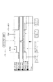
図1は、本発明を適用した情報処理システムの一実施の形態の構成を示す図である。GPS装置1は、図示されていない衛星からの信号を受信し、その信号を解析することにより、受信位置(緯度、経度など)を算出し、その位置情報を記憶する。また、衛星には、通常、原子時計を搭載しており、GPS装置1は、受信した信号から時刻情報を得ることも可能であり、その得た時刻情報も記憶する。以後、GPS装置1に記憶される位置情報および時刻情報などを含む情報をログデータと称する。デジタルカメラ2は、被写体の画像を撮像し、フロッピーディスク3などの記録媒体(以下、デジタルビデオカメラ2により撮像された画像は、フロッピーディスク3に記憶されるとして説明する)に、撮像した画像のデータを記憶する。
FIG. 1 is a diagram showing a configuration of an embodiment of an information processing system to which the present invention is applied. The
なお、デジタルカメラ2において撮像された画像を記録する記録媒体としては、フロッピーディスク3以外にも、携帯用半導体メモリ5などの記録媒体などでも良い。また、通信機能を備えるデジタルカメラ2では、撮像した画像のデータを他の装置に伝送し、その伝送された先の装置で記憶されるようにしても良い。
As a recording medium for recording an image captured by the
パーソナルコンピュータ4は、GPS装置1とUSB(Universal Serial Bus)により接続され、GPS装置1が記憶したログデータが供給される。また、パーソナルコンピュータ4は、デジタルカメラ2ともUSBで接続可能であり、記憶されている画像データを読み出すことができるとともに、フロッピーディスク3から画像データを読み出すことも可能である。
The
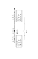
図2は、パーソナルコンピュータ4の内部構成を示すブロック図である。パーソナルコンピュータ4のCPU11は、ROM(Read Only Memory)12に記憶されているプログラムに従って各種の処理を実行する。RAM(Random Access Memory)13には、CPU11が各種の処理を実行する上において必要なデータやプログラムなどが適宜記憶される。入出力インタフェース(I/F)14には、キーボード15とマウス16が接続されており、それらから入力された信号をCPU11に出力する。また、入出力I/F14には、FDD(Floppy Disk Drive)17とハードディスク(HDD)18も接続されており、そこにデータ、プログラムなどを記録、再生することができる。入出力I/F14には、また、表示デバイスとしてのディスプレイ18が接続されているとともに、USBポート20を介して、例えば、GPS装置1とも接続されている。内部バス21は、これらの各部を相互に接続する。
FIG. 2 is a block diagram showing an internal configuration of the
図3は、GPS装置1の外観を表す図である。図3(A)は正面から見た図、図3(B)は背面から見た図、図3(C)は右側面から見た図、図3(D)は下面から見た図を、それぞれ表している。GPS装置1は、アンテナ31と本体32とから構成されており、アンテナ31は、本体32に対して、背面方向に回動するように取り付けられている。本体32には、GPSランプ33、RECランプ34、およびPOWERランプ35の計3個のランプと、マークボタン36とパワーボタン37の計2個のボタンが備えられている。また、本体32には、PC装着部38も備えられている。
FIG. 3 is a diagram illustrating the appearance of the
PC装着部38は、ノート型のパーソナルコンピュータ4(モバイルコンピュータ)に装着する際に用いられ、本体32に対して前後に移動するように構成されている。図3(C)では、本体32に対して前方向に伸ばされた(引き出された)状態を示しているが、普段は邪魔にならないように、本体32に収納される。PC装着部38は、バネ(不図示)が付けられており、引き延ばされた状態から手を離すと、自然に本体32に収納されるようにされている。
The
図3(C)に示したように、PC装着部38が、本体32に対して引き出された状態の場合、ノート型のパーソナルコンピュータ4に装着することが可能となる。すなわち、図4に示すように、パーソナルコンピュータ4を開いた状態で、そのディスプレイ19の上部に、PC装着部38と本体32に、そのディスプレイ19の一端が挟まるようなかたちで掛けるようにすることで、GPS装置1をパーソナルコンピュータ4に装着することができる。上述したように、PC装着部38にはバネが装着されているため、ディスプレイ19を本体32とで、適度な圧力で挟むことができるので、パーソナルコンピュータ4に振動などが加わった場合にも、GPS装置1が落下するなどの不都合を防ぐことができる。
As shown in FIG. 3C, when the
図4に示したように、パーソナルコンピュータ4にGPS装置1を装着したとき、俗にカーナビと称されるナビゲーションシステムとして用いることが可能となる。パーソナルコンピュータ4にナビゲーションシステムを実行させるための所定のアプリケーションを実行させる。そのアプリケーションは、ディスプレイ19上に現在位置を含む地図を表示したりする。現在位置を表示するためのデータは、GPS装置1から得られる位置情報を用いて算出される。このように、ナビゲーションシステムとしてパーソナルコンピュータ4およびGPS装置1を用いる場合、上述したように、アンテナ31は本体32に対して回動可能に構成されているので、衛星からの信号を受信しやすいように、図4に示したように、アンテナ31を本体32に対して角度を付けて固定する(衛星からの信号を受信しやすい角度で固定する)ことが可能である。
As shown in FIG. 4, when the
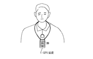
また、GPS装置1は、ユーザが持ち運びして利用することが可能であり、そのような場合、ユーザは、PS装着部38を、本体32に格納するような形で、持ち運びに邪魔にならないようにし、ストラップ装着部39(図3(B))に、ストラップを装着し、そのストラップを首やベルトなどに引っかけて携帯することが可能である。例えば、図5に示すように、ユーザは、長めのストラップをストラップ装着部39に装着した場合、GPS装置1を首からかけて携帯することができる。
In addition, the
GPS装置1は、図3(B)に示すように、その背面に電池蓋40があり、その電池蓋40を図中右方向にずらすことにより、蓋が開くようになっている。電池は、1次電池、2次電池のどちらを用いることも可能である。2次電池を用いる場合、GPS装置1に2次電池を装着したまま、充電できるような機能を備えるような構造としても良い。また、GPS装置1は、USBポート41を備えることにより、パーソナルコンピュータ2とデータの授受を行えるように構成されている。
As shown in FIG. 3 (B), the
図6は、GPS装置1の内部構成を示す図である。上述したように、GPS装置1はアンテナ31と本体32とから構成されており、本体32には、さまざまな処理を行う回路が納められている。図6は、それらの回路を機能的にまとめて示したブロック図である。操作部51は、ユーザが所望の操作を行う際に操作されるマークボタン36やパワーボタン37から構成されている。記憶部52は、ログデータを記憶する。
FIG. 6 is a diagram showing an internal configuration of the
制御部53は、アンテナ31により受信された信号を基に、ログデータを生成し、記憶部52に記憶させたり、USBポート41や操作部51から入力される信号に対応する処理を実行する。電力供給部54は、電池(バッテリー)から供給される電力または、USBポート41を介してパーソナルコンピュータ4から供給される電力を、GPS装置1の各部に供給する。カウンタ部55は、時刻を管理したり、後述する各種のカウンタ値を管理し、その管理情報を制御部53に提供する。
The
ここで、GPS装置1には、GPSモード、PCモード、記憶モードの3つのモードが定義されており、それぞれのモードの意味は、以下の通りである。まず、GPSモードは、パーソナルコンピュータ4と接続され、ナビゲーションシステムの際のGPS信号の受信アンテナとして用いられる時のモードである。PCモードは、パーソナルコンピュータ4と接続され、パーソナルコンピュータ4からの命令に従い、記憶部52に記憶されているログデータを出力したり、各種の設定を行ったりするモードである。記憶モードは、例えば、ユーザに携帯され、ログデータを記憶部52に記憶していくモードである。
Here, the
さらに記憶モードは、ウェイクステート、スリープステート、およびウェイクアップステートの、3つのステートに分類される。ウェイクステートは、記憶動作を実行している状態を示す。それに対してスリープステートは、記憶動作を停止している状態を示す。ウェイクアップステートは、スリープステート中に、一時的にウェイクステートの状態にし、記憶動作を行い、再びスリープステートの状態に戻る状態を示している。 Further, the storage mode is classified into three states: a wake state, a sleep state, and a wake-up state. The wake state indicates a state in which a storage operation is being performed. On the other hand, the sleep state indicates a state where the storage operation is stopped. The wake-up state indicates a state in which, during the sleep state, the state is temporarily changed to the wake state, the storage operation is performed, and the state is returned to the sleep state again.
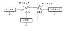
GPS装置1は、内部にスイッチを備えており、制御部53は、上述した3つのモードに従って、そのスイッチを切り換える。具体的には、図7に示すようにスイッチ61とスイッチ62が備えられている。制御部53は、GPSモードのときは、スイッチ61を端子A1に、スイッチ62を端子B1に、それぞれ接続させる。
The
PCモードのときは、スイッチ61は、端子A1、若しくは、端子A2に、スイッチ62は、端子B2に、それぞれ接続される。PCモードのときは、GPS装置1は、パーソナルコンピュータ4からのコマンドに従って動作するため、コマンドが、GPSとして動作せよ(アンテナ31で受信された信号を出力せよ)という意味を含むものである場合、スイッチ61は、端子A1と接続され、記憶部52に記憶されているログデータを出力せよという意味を含むものである場合、スイッチ62は、端子A2と接続される。なお、スイッチ61は、パーソナルコンピュータ4と通信(データの授受)が行える状態にあると判断された場合には、強制的に(初期設定として)、端子A1と接続され、パーソナルコンピュータ4と通信が行えない状態にあると判断される場合には、端子A2と接続されるように構成されている。
In the PC mode, the switch 61 is connected to the terminal A1 or the terminal A2, and the switch 62 is connected to the terminal B2. In the PC mode, the
制御部53は、記憶モードの時は、スイッチ61を端子A2と接続させる。記憶モードのときは、パーソナルコンピュータ4とは接続されていない状態なので、スイッチ62は、基本的に、端子B1でも端子B2でも、どちらに接続されていても問題はない。そこで、記録モードの時は、スイッチ62は、デフォルトとして端子B1と接続される。
The
次に、図8のフローチャートを参照して、GPS装置1の動作について説明する。図8のフローチャートを参照して説明するGPS装置1の動作は、パーソナルコンピュータ4と接続されていない状態、換言すれば、GPSモードまたはPCモードのどちらでもなく、記憶モードの状態である場合である。
Next, the operation of the
制御部53は、ステップS1において、パワーボタン37が操作されたか否かを判断する。ステップS1における処理は、パワーボタン37が操作されたと判断されるまで繰り返し行われ(すなわち、パワーボタン37が操作されるまで、GPS装置1は状態を維持する)、パワーボタン37が操作されたと判断された場合、ステップS2に進む。ステップS2においてウェイクステートであるか否かが判断される。
In step S1, the
ステップS2において、ウェイクステートであると判断された場合、すなわち、GPS装置1は、既に電源がオンにされており、ログデータの記憶が実行されている状態で、パワーボタン37が操作されたと判断された場合、ステップS3に進む。ステップS3において、パワーボタン37が操作されたのは3秒以上であるか否かが判断される。ここでは、3秒を基準値として設定した場合を例に挙げて説明するが、他の秒数を基準値として設定しても良い。このような基準値を設けるのは、ユーザが、GPS装置1の電源をオンまたはオフさせるという処理を所望として、パワーボタン37が操作されたのか、後述するステップS7の処理を実行させるために操作されたのか、または、例えば、ユーザのベルトなどに装着されて持ち運びされている際に、ユーザの意志とは反して操作されてしまった(誤操作)のかを区別するためである。
If it is determined in step S2 that the state is the wake state, that is, the
ステップS3において、パワーボタン37が操作されたのは3秒以上ではないと判断された場合、誤操作と判断され、何も処理は実行されない。一方、ステップS3において、パワーボタン37が操作されたのは、3秒以上であると判断された場合、ステップS4において、パワーオフの処理が実行される。
If it is determined in step S3 that the
図9は、ステップS4のパワーオフの処理の詳細を示すフローチャートである。パワーがオフされる際、ステップS21において、まず、アンテナ31からの信号の供給が停止される。ステップS22において、エンドフラグが1に設定される。ここで、記憶されるログデータの構造について説明する。1つのログデータは、図10(A)に示すように19バイトの固定長のデータとして構成される。なお、以下に挙げるバイトサイズは、一例であり、その他のバイトサイズをとっても良い。
FIG. 9 is a flowchart showing details of the power-off process in step S4. When the power is turned off, first, supply of a signal from the
19バイトのログデータのうち、1バイトはフラグのデータが、17バイトはログデータのデータ本体が、残り1バイトはステータスのデータが、それぞれ割り当てられている。フラグデータは、図10(B)に示すようなデータ構成とされている。1バイトのフラグデータのうち、スタートフラグ、エンドフラグ、マークフラグ、およびO/Gフラグが、それぞれ1ビットづつ割り当てられており、残り4ビットが、ELS用として割り当てられている。 Of the 19 bytes of log data, 1 byte is assigned flag data, 17 bytes is assigned the log data body, and the remaining 1 byte is assigned status data. The flag data has a data structure as shown in FIG. Of the 1-byte flag data, a start flag, an end flag, a mark flag, and an O / G flag are each assigned 1 bit, and the remaining 4 bits are assigned for ELS.
スタートフラグは、記憶モードの開始により、記憶が開始された最初のログデータであることを示す場合、値が1に設定され、それ以外のとき(記憶モードが開始されてから2個目以降のログデータであることを示す場合)、値が0に設定される。同様に、エンドフラグは、記憶モードの開始により、記憶が開始された最後のログデータであることを示す場合、値が1に設定され、それ以外のとき、値が0に設定される。 The start flag is set to 1 when it indicates the first log data that has been stored due to the start of the storage mode, and otherwise (the second and subsequent data after the storage mode has started). If it is log data), the value is set to zero. Similarly, when the end flag indicates that the log data is the last log data that has been started due to the start of the storage mode, the value is set to 1; otherwise, the value is set to 0.
マークフラグは、マークボタン36が操作された際(詳細は後述)に、記憶されたログデータであることを示す場合、値が1に設定され、それ以外の場合、値が0に設定される。
The mark flag is set to 1 when the
O/Gフラグの値が1であり、かつ、スタートフラグが0の場合、そのログデータは記憶時のデータではなく、記憶時より前の時刻において記憶されたデータ内で最も新しいデータであることを示し、O/Gフラグが0であり、かつ、スタートフラグが0の場合、記憶されたログデータが記憶時のデータであることを示す。O/Gフラグが1であり、かつ、スタートフラグが1である場合(すなわち、記憶を開始して一番初めに記憶されたログデータを示す場合)、記憶が開始されてから終了されるまでのログデータが東京測地系であることを示し、O/Gフラグが0であり、かつ、スタートフラグが1である場合、記憶が開始されてから終了されるまでのログデータがWGS84(World Geodetic System:全世界測地系)であることを示す。 If the value of the O / G flag is 1 and the start flag is 0, the log data is not the data at the time of storage but the newest data stored at the time prior to the time of storage. When the O / G flag is 0 and the start flag is 0, it indicates that the stored log data is data at the time of storage. When the O / G flag is 1 and the start flag is 1 (that is, when the first stored log data is indicated after the start of storage), from the start of storage until the end Indicates that the log data is from the Tokyo Geodetic System, the O / G flag is 0, and the start flag is 1, the log data from the start of storage to the end is stored in WGS84 (World Geodetic System: Global Geodetic System).
ログデータ本体は、図10(C)に示すように構成されており、17バイトの内、6バイトは日付時刻、0.5バイトは緯度経度半球、3.5バイトは緯度、4バイトは経度、1.5バイトは速度、残り1.5バイトは方位を、それぞれ示す。 The log data body is configured as shown in FIG. 10C. Of the 17 bytes, 6 bytes are the date and time, 0.5 bytes are the latitude and longitude hemisphere, 3.5 bytes are the latitude, and 4 bytes are the longitude. , 1.5 bytes indicate speed, and the remaining 1.5 bytes indicate direction.
日付時刻は、UTC(Universal Time Coordinated)に基づく、年、月、日、時、分、および秒を示す。緯度経度半球は、以下の緯度および経度に係わるデータであり、最上位のビットが0の場合、以下の緯度が、北半球(北緯)であることを示し、1の場合、南半球(南緯)であることを示し、最上位ビットの次のビットが0の場合、東半球(東経)であることを示し、1の場合、西半球(西経)であることを示す。 The date time indicates a year, month, day, hour, minute, and second based on UTC (Universal Time Coordinated). The latitude-longitude hemisphere is data relating to the following latitude and longitude. When the most significant bit is 0, the following latitude is the northern hemisphere (north latitude), and when 1, the southern hemisphere (south latitude). When the next bit of the most significant bit is 0, it indicates the east hemisphere (east longitude), and when it is 1, it indicates the west hemisphere (west longitude).
緯度は、7桁の数字形式で表されたもののデータであり、経度は、8桁の数字形式で表されたもののデータである。速度は、3桁の数字で表されたもののデータであり、単位は1Km/hである。また、方位は、ユーザが進行している方位を示し、北を0度として右回りに360度まで1度単位で刻まれた、3桁数字で表されたもののデータである。 The latitude is data expressed in a 7-digit number format, and the longitude is data expressed in an 8-digit number format. The speed is data represented by a three-digit number, and the unit is 1 km / h. Further, the azimuth indicates the azimuth in which the user is traveling, and is data of a three-digit number that is inscribed in units of 1 degree clockwise from 360 degrees with north as 0 degrees.
図9のフローチャートの説明に戻り、ステップS22において、上述したログデータのうちのエンドフラグを1に設定すると、ステップS22において、記憶処理が行われる。図11は、記憶処理の詳細を示すフローチャートである。この処理は、上述したログデータを作成し、記憶部52(図6)に記憶させるために行われる。 Returning to the description of the flowchart of FIG. 9, when the end flag of the log data described above is set to 1 in step S22, storage processing is performed in step S22. FIG. 11 is a flowchart showing details of the storage process. This process is performed to create the log data described above and store it in the storage unit 52 (FIG. 6).
ステップS32において、制御部53は、記憶部52の記憶可能領域を調べ、記憶可能領域が1個のログデータを記憶させるだけのスペースがあるか否か、すなわち、この場合、19バイトのスペースがあるか否かを判断する。記憶可能領域が19バイトの空きもないと判断された場合、ステップS32に進み、RECランプ34が点灯される。RECランプ34は、例えば、赤色であり、記憶可能領域のあきがないためにログデータを記憶させることができない間中ずっと、赤く点灯され続ける。
In step S32, the
一方、ステップS31において、記憶部52の記憶可能領域にログデータを記憶するだけの空きがあると判断された場合、ステップS33に進む。ステップS33において、上述したようなログデータが作成され、指定された記憶部52のアドレスに記憶される。ステップS34において、次のログデータを記憶させるためのアドレスの設定が行われる。すなわち、アドレス値が19だけ加算される。
On the other hand, if it is determined in step S31 that there is enough space to store log data in the storable area of the
このようにして、作成されたログデータが記憶されると、そのことをユーザに知らせるために、ステップS35において、RECランプ34が、0.1秒間だけ点灯される。ステップS36において、記憶可能領域が、コーションレベルより小さいか否かが判断される。コーションレベルは、記憶部52の記憶可能領域の大きさ、すなわち、記憶部52の残量が、所定値以下になったら、そのことをユーザに知らせる処理を実行するために設定されたレベル値である。このコーションレベルは、デフォルトとして、記憶部52の容量(ログデータを記憶させるための領域)の10%を切った時点と設定される。この設定は、後述するように、ユーザにより、変更できるようにされている。
When the created log data is stored in this way, the
記憶部52の容量としては、例えば、1秒毎にログデータを記憶していっても7.5時間ぐらいは記憶できる容量として設定される。このようにして設定した場合、具体的には、記憶部52の容量は、513000(=19バイト×60秒×60分×7.5時間)バイトとなる。従って、コーションレベルを容量の10%として設定した場合、そのレベル値は、51300バイトとなる。
The capacity of the
ステップS36において、記憶可能領域がコーションレベルよりも小さいと判断された場合、ステップS37に進む。ステップS37において、記憶部52の記憶可能な容量が、残り少なくなってきたことをユーザに知らせるために、RECランプ34が0.3秒毎に、継続的に点滅される。さらに、ステップS38において、ビープ音が出される。ビープ音としては、どのような音色、音量、メロディーでも良いが、ユーザが聞いただけでGPS装置1の状況を判断できるように、状況に応じて異なるメロディー、音色で出される方が良い。例えば、記憶部52の容量が残り少なくなった事を知らせるビープ音のメロディーとしては、”ピ・ピ・ピ・・・・”といった連続音である。
If it is determined in step S36 that the storable area is smaller than the caution level, the process proceeds to step S37. In step S37, the
ユーザが、このような記憶部52の記憶可能な容量が少なくなってきたことを知らせる警告に対して何らかの処理、例えば、記憶動作を終了させる(パワーをオンにする)、必要ないログデータを削除するなどの処理を行わず、ログデータの記憶動作を継続させ、記憶部52の記憶可能な容量がなくなった場合、GPS装置1のパワーはオフにされる。このようにすることにより、一旦記憶されたログデータは、ユーザによる指示がない限り保持され、後でユーザが用いたいと思っていたログデータが削除されているといった不都合をなくすことが可能となる。
In response to a warning informing the user that the storage capacity of the
一方、ステップS36において、記憶可能領域がコーションレベルよりも大きいと判断された場合、ステップS37,S38の処理は省略され、記憶処理は終了される。 On the other hand, if it is determined in step S36 that the storable area is larger than the caution level, the processes in steps S37 and S38 are omitted, and the storage process is terminated.
記憶処理が終了されると、ステップS24(図9)において、全てのランプがオフの状態にされる。すなわち、GPSランプ33、RECランプ34、およびPOWERランプ35の点灯または点滅が停止される。そして、ステップS25において、パワーオフの処理が終了したことをユーザに知らせるために、ビープ音が出される。ビープ音のメロディーとしては、例えば、”ピ、ピッ”である。
When the storing process is completed, all the lamps are turned off in step S24 (FIG. 9). That is, lighting or blinking of the GPS lamp 33, the
図8のフローチャートの説明に戻り、ステップS2において、ウェイクステートではないと判断された場合、ステップS5に進み、スリープステートであるか否かが判断される。ステップS5において、スリープステートであると判断された場合、ステップS6に進み、ステップS3の処理と同様に、パワーボタン37が操作されたのは3秒以上であるか否かが判断される。ステップS6において、パワーボタン37が操作されたのは、3秒以上であると判断された場合、ステップS4に進む。ステップS4の処理は、既に説明したので、省略する。
Returning to the description of the flowchart of FIG. 8, if it is determined in step S2 that the wake state is not set, the process proceeds to step S5 to determine whether or not the wake state is set. If it is determined in step S5 that the sleep state is set, the process proceeds to step S6, and it is determined whether or not the
一方、ステップS6において、パワーボタン37が操作されたのは、3秒以上ではないと判断された場合、ステップS7に進み、ウェイクアップ処理が実行される。図12は、ウェイクアップ処理の詳細を示すフローチャートである。
On the other hand, if it is determined in step S6 that the
ステップS51において、制御部52は、ログデータの記憶を開始するための初期設定を行う。初期設定としては、例えば、スリープステートの状態では、アンテナ31で受信された信号の供給が停止されている(アンテナ31への電力の供給が停止されている)ので、信号を受信できる状態にするなどの設定が行われる。
In step S51, the
ステップS52において、ウェイクアップの状態であることをユーザに知らせる為に、POWERランプ35が緑色で点灯される。POWERランプ35は、状況に応じ、緑色または赤色で点灯(点滅)するようにされている。同様に、GPSランプ33も、状況に応じ、緑色または赤色で点灯(点滅)するようにされている。勿論、他の色で点灯されるようにしても良いが、ここでは、上述したように、緑色と赤色を用いた場合を例に挙げて説明する。
In step S52, the
ステップS53において、さらにウェイクアップの状態になったことをユーザに知らせる為に、ビープ音が出される。ビープ音のメロディーとしては、例えば、”ピッ”である。 In step S53, a beep sound is emitted to inform the user that the wake-up state has been reached. An example of a beep melody is “beep”.
GPS装置1は、ログデータを記憶できる状態になると、設定されたウェイクタイムだけ、ウェイクステートと同じ状態になり、ログデータの記憶が行われる。ウェイクタイムとは、スリープステートの状態を解除している時間(ウェイクアップステートの継続時間)を示し、ユーザが後述する処理により設定することも可能であるし、デフォルトとして、10分(600秒)などと設定された値を用いる事も可能である。
When the
設定されたウェイクタイムが経過するまで、ログデータの記憶などの所定の処理が実行され、ウェイクタイムが経過すると、再びスリープステートの状態に戻る。なお、ウェイクタイムが経過すると、スリープステートに戻るが、ユーザが、パワーボタン37を操作した場合にも、スリープステートの状態に戻る。
Predetermined processing such as storage of log data is executed until the set wake time elapses, and when the wake time elapses, the state returns to the sleep state again. When the wake time elapses, the state returns to the sleep state. However, when the user operates the
ステップS55において、スリープステートに戻ることをユーザに知らせるために、POWERランプ35が4秒ごとに赤色で点滅(スリープステートの状態である時は、POWERランプは4秒ごとに赤色で点滅する)し、GPSランプ33の点灯は、消される。さらに、ステップS56において、”ピッ”というビープ音が出される。
In step S55, the
このようにして、スリープステートの時であっても、ユーザの所望のときに、所定時間だけ、ログデータを記憶させる処理を実行させることが可能である。 In this manner, even in the sleep state, it is possible to execute a process of storing log data for a predetermined time when desired by the user.
図8のフローチャートの説明に戻り、ステップS5において、スリープステートではないと判断された場合、ステップS8に進み、パワーボタン37が操作されたのは、3秒以上であるか否かが判断される。ステップS8において、パワーボタン37が操作されたのは、3秒以上ではないと判断された場合、ステップS3と同様に、その操作は誤操作として処理され、特に所定の処理は実行されない。
Returning to the description of the flowchart of FIG. 8, if it is determined in step S5 that the sleep state is not set, the process proceeds to step S8, and it is determined whether or not the
一方、ステップS8において、パワーボタン37が操作されたのは、3秒以上であると判断された場合、ステップS9に進む。ステップS2においてウェイクステートではないと判断され、ステップS5において、スリープステートでもないと判断されているので、GPS装置1の状態としては、パワーがオフにされている状態であると判断できる。そして、そのような状態で、ユーザがパワーボタン37を操作したということは、パワーをオンさせたいと所望したと判断できるので、ステップS9においては、パワーオンの処理が実行される。
On the other hand, if it is determined in step S8 that the
図13は、パワーオンの処理の詳細を説明するフローチャートである。ステップS71において、制御部53は、操作部51から入力された信号により、パワーボタン37が操作されたことを判断し、パワーオンするための初期設定を行う。ステップS72において、POWERボタン37が緑色で点灯される。
FIG. 13 is a flowchart for explaining the details of the power-on process. In step S <b> 71, the
ステップS73において、スタートフラグが1に設定され、O/Gフラグが1または0に設定される。O/Gフラグは、上述したように、スタートフラグが1の場合でかつ東京測地系である場合、1に設定され、スタートフラグが1の場合でかつWGS84である場合、0に設定される。このように、フラグが設定されると、ステップS74において、記憶処理が実行される。この記憶処理は、図11のフローチャートを参照して既に説明したので、その説明は省略する。 In step S73, the start flag is set to 1 and the O / G flag is set to 1 or 0. As described above, the O / G flag is set to 1 when the start flag is 1 and the Tokyo geodetic system, and is set to 0 when the start flag is 1 and WGS84. As described above, when the flag is set, the storage process is executed in step S74. Since this storage process has already been described with reference to the flowchart of FIG. 11, the description thereof is omitted.
ステップS75において、GPS装置1のパワーがオンされたことをユーザに知らせるために、”ピー”というビープ音が出される。そして、ステップS76において、スリープタイムが0であるか否かが判断される。スリープタイムは、ログデータを記憶した時点からどれだけの時間、スリープステートの状態にするかを指定するものであり、換言すれば、どの程度のタイミングでログデータを記憶するかを決定するパラメータである。
In step S75, in order to notify the user that the power of the
スリープタイムが0である場合、すなわち、スリープステートがない状態、従って、ウェイクステートの状態が連続する状態に設定されていることを意味する。一方、スリープステートが0以外の値に設定されている場合、その設定されている間だけスリープステートの状態で、その他の時間は、ウェイクステートの状態であることを、すなわち、スリープステートとウェイクステートが繰り返されることにより、間欠的に(ウェイクステートのときだけ)ログデータの記憶が行われることを意味している。ウェイクステートの状態は、最大ウェイクタイムとして設定された時間だけ継続される。 When the sleep time is 0, that is, it means that there is no sleep state, and therefore the wake state is set to a continuous state. On the other hand, if the sleep state is set to a value other than 0, it is in the sleep state only while the sleep state is set, and the rest of the time is in the wake state, that is, the sleep state and the wake state By repeating the above, log data is stored intermittently (only in the wake state). The state of the wake state is continued for the time set as the maximum wake time.
スリープタイムや、ウェイクタイムは、ユーザにより設定することが可能であるし、デフォルトとして例えば、スリープタイムは2分(120秒)、ウェイクタイムは10分(600秒)として設定しておくことも可能である。 The sleep time and wake time can be set by the user. For example, the sleep time can be set to 2 minutes (120 seconds) and the wake time can be set to 10 minutes (600 seconds). It is.
ステップS76において、スリープタイムが0ではないと判断された場合、ステップS77に進み、間欠動作の処理が実行される。図14は、間欠動作の処理の詳細を説明するフローチャートである。ステップS91において、ウェイクタイムをカウントするカウンタ部55(図6)のカウンタ値が、設定されているウェイクタイムの時間に設定される。 If it is determined in step S76 that the sleep time is not zero, the process proceeds to step S77, and intermittent operation processing is executed. FIG. 14 is a flowchart for explaining details of the intermittent operation processing. In step S91, the counter value of the counter unit 55 (FIG. 6) that counts the wake time is set to the set wake time.
ステップS92において、GPSデータを取得する。GPSデータは、1秒ごとに取得される。そのデータは、衛星からの信号を受信したものである場合は、そのデータがNEWデータとして用いられるが、衛星からの信号が受信できなかった場合においても、衛星からの信号で得られた最も新しいデータをOLDデータとして用いられるようになっている。そこで、ステップS93においては、ステップS92において得られたGPSデータは、新しいデータ(衛星からの信号により得られた)データであるか否かが判断される。 In step S92, GPS data is acquired. GPS data is acquired every second. If the data is received from a satellite, the data is used as NEW data. However, even if the signal from the satellite cannot be received, the newest data obtained from the satellite is used. Data can be used as OLD data. Therefore, in step S93, it is determined whether or not the GPS data obtained in step S92 is new data (obtained from a signal from a satellite).
ステップS93において、新しいデータではないと判断された場合、ステップS94に進む。ステップS94において、カウンタ部55のカウンタ値が1だけ減算される。すなわち、1秒だけ減算される。そしてステップS95において、カウンタ値が0であるか否かが判断される。換言すれば、ウェイクタイムが経過したか否かが判断される。ステップS95において、カウンタ値が0ではないと判断された場合、ステップS92に戻り、それ以降の処理が繰り返され、カウンタ値が0であると判断された場合、ステップS97に進む。
If it is determined in step S93 that the data is not new data, the process proceeds to step S94. In step S94, the counter value of the
一方、ステップS93において新しいデータであると判断された場合、ステップS96に進む。ステップS96の記憶処理は、既に説明したので、その説明は省略する。記憶処理が終了されると、ステップS97に進み、設定されたスリープ時間だけ、スリープステートで待機される。すなわち、間欠動作のときは、ウエイクステートになってから、衛星からの信号によりGPSデータが得られた時点で、記憶処理が行われ、そして、すぐにスリープステートの状態に戻る。このように、新しいデータが得られたらすぐにスリープステートの状態に戻ることにより、電力の無駄な消耗を省くことができる。 On the other hand, if it is determined in step S93 that the data is new, the process proceeds to step S96. Since the storage process in step S96 has already been described, the description thereof is omitted. When the storing process is completed, the process proceeds to step S97, where the process waits for the set sleep time in the sleep state. That is, during intermittent operation, after entering the wake state, when GPS data is obtained from a signal from the satellite, storage processing is performed, and the state immediately returns to the sleep state. As described above, by returning to the sleep state as soon as new data is obtained, unnecessary power consumption can be eliminated.
例えば、設定されたスリープステートの継続時間(スリープタイム)が2分であり、ウェイクステートの継続時間(ウェイクタイム)が1分である場合、室内など、衛星からの信号を受信できない状態のときには、3分ごとにログデータの記憶が行われることになる。それに対し、野外などで衛星からの信号を受信しやすい状態で、ウェイクステートになってから1秒目でログデータが記憶されれば、約2分毎にログデータが記憶されることになる。 For example, when the set sleep state duration (sleep time) is 2 minutes and the wake state duration (wake time) is 1 minute, when the signal from the satellite cannot be received, such as indoors, Log data is stored every three minutes. On the other hand, if log data is stored in the first second after entering the wake state in a state where it is easy to receive a signal from a satellite in the outdoors, the log data is stored about every two minutes.
なお、ウェイクステート中に、一度も衛星からの信号を受信できなかった(NEWデータを得られなかった)場合、ステップS96の処理が一度も行われないことになるので、ログデータの記憶は行われない。 Note that if the signal from the satellite has never been received (new data has not been obtained) during the wake state, the process of step S96 is never performed, so the log data is not stored. I will not.
ステップS97において、設定されたスリープタイムだけスリープステートで待機されたら、ステップS91に戻り、再びウェイクステートの状態となり、それ以降の処理が繰り返される。 In step S97, when waiting in the sleep state for the set sleep time, the process returns to step S91 to enter the wake state again, and the subsequent processing is repeated.
このようなフローチャートの処理は、パワーボタン37が操作されたとき、記憶部52の記憶可能領域がなくなったとき、電力供給部54から供給される電力(バッテリーの容量)がなくなったときなどに、割り込み処理として終了され、それぞれの状況に応じた処理が実行される。
The processing of such a flowchart is performed when the
図13のフローチャートの説明に戻り、ステップS76において、スリープタイムが0に設定されていると判断された場合、ステップS78に進み、連続動作の処理が実行される。図15は、連続動作の処理の詳細を説明するフローチャートである。ステップS111において、インターバルタイムをカウントするカウンタ値が、設定されているインターバルタイムの時間に設定される。インターバルタイムは、ログデータの記憶密度を設定するものであり、1秒乃至1時間までの間で任意に設定される。デフォルトの値としては、例えば、5秒であり、5秒毎に、ログデータが記憶されることを意味している。 Returning to the description of the flowchart of FIG. 13, when it is determined in step S76 that the sleep time is set to 0, the process proceeds to step S78, and a process of continuous operation is executed. FIG. 15 is a flowchart for explaining the details of the continuous operation processing. In step S111, the counter value for counting the interval time is set to the set interval time. The interval time sets the storage density of log data, and is arbitrarily set between 1 second and 1 hour. The default value is, for example, 5 seconds, which means that log data is stored every 5 seconds.
ステップS112乃至ステップS116の処理は、図14のステップS92乃至S96と同様の処理なので、その説明は省略する。ステップS116における記憶処理が終了されると、ステップS117において、残りのカウンタ値だけ待機状態(ログデータの記憶などの処理を行わない状態)とされる。例えば、インターバルタイムが5秒として設定されていた場合、5秒間待機状態であり、その後、ログデータの記憶が行われ、再び5秒間の待機機状態になるといった動作が繰り返される。ステップS117における待機状態が終了されると、ステップS111に戻り、それ以降の処理が繰り返される。 The processing from step S112 to step S116 is the same as the processing from step S92 to S96 in FIG. When the storage process in step S116 is completed, in step S117, the remaining counter value is set in a standby state (a state in which processing such as storage of log data is not performed). For example, when the interval time is set as 5 seconds, the operation is in the standby state for 5 seconds, the log data is then stored, and the standby device state for 5 seconds is entered again. When the standby state in step S117 ends, the process returns to step S111, and the subsequent processing is repeated.
なお、ログデータは、衛星からの信号を受信できた時のみ記録され、受信できなかったときは、記録せずに、待機状態となる。また、インターバルタイムが、1分を越える時間で設定されている場合、待機状態は、スリープモードとして待機する。このことにより、連続動作であっても、間欠動作と同様に電力の消耗を防ぐことができる。 The log data is recorded only when a signal from the satellite can be received. When the signal cannot be received, the log data is not recorded and enters a standby state. When the interval time is set to a time exceeding 1 minute, the standby state is a standby mode. As a result, even in a continuous operation, power consumption can be prevented as in the intermittent operation.
図15に示した連続動作の処理を説明するフローチャートの処理は、間欠動作の処理と同様に、パワーボタン37が操作されたとき、記憶部52の記憶可能領域がなくなったとき、電力がなくなったときなどに、割り込み処理として終了される。
The process of the flowchart for explaining the process of the continuous operation shown in FIG. 15 loses power when the
次に、マークボタン36が操作された際の処理について説明する。マークボタン36は、記録モードの場合で、ウェイクステートまたはウェイクアップステートのときに、操作されると所定の処理が実行される。ウェイクステート、ウェイクアップステート、どちらの状態であっても、GPS測位中の状態とGPS測位不可の状態(アンテナ31により衛星からの信号を受信している状態と受信していない状態)とが存在する。
Next, processing when the
GPS測位中であるときに、マークボタン36が操作された場合、操作された時点での位置情報や時刻情報がログデータとして記憶される。この際、記録モードのときに設定されてるインターバルタイムなどとは、全く無関係に行われる。すなわち、ログデータを記憶するタイミングでなくても、マークボタン36が操作された時点で、ログデータは記憶される。GPS測位不可である状態のときも同様であるが、GPS測位不可であるので、新しいデータでの位置情報を含むログデータを記憶(作成)することができない。そこで、衛星からの信号により得られたデータのうち、最も新しい位置情報(OLDデータ)を含むログデータが作成される。
When the
時刻情報は、カウンタ部55から供給される。カウンタ部55は、時刻も管理しており、衛星からの信号を受信することができたときは、その信号による時刻を基に、自己が管理している時刻を補正しする。また、カウンタ部55は、衛星からの信号が得られないときに、マークボタン36が操作された際には、自己が管理している時刻情報を制御部53に提供する。制御部53は、提供された時刻情報を含むログデータを作成し、記憶部52に記憶させる。
The time information is supplied from the
このようにして、マークボタン36が操作されたことにより記憶されるデータには、マークフラグが立てられて(値が1として設定されて)記憶される。また、OLDデータを含むログデータの場合は、O/Gフラグの値が1とされて記憶される。
In this way, a mark flag is set (stored with a value of 1) and stored in the data stored when the
上述した処理によるログデータの記憶について、図16乃至図18のタイミングチャートを参照して、さらに説明する。図16は、記録モード時の連続動作によるログデータの記憶を説明するタイミングチャートである。所定の時刻において、パワーボタン37が操作されることにより、GPS装置1のパワーがオンにされると、スタートフラグが1に設定され、ログデータの記憶が開始される。連続動作によるログデータの記憶は、設定されたインターバルタイムの周期毎に行われる。
The storage of log data by the above-described processing will be further described with reference to the timing charts of FIGS. FIG. 16 is a timing chart for explaining storage of log data by continuous operation in the recording mode. When the power of the
従って、図16において、P0とP1、P1とP2、・・・、P5とP6の時間間隔は同一である。GPSランプ33は、衛星からの信号を正常に受信しているときは緑色に点灯し、信号を正常に受信していないときは赤色に点灯している。所定のインターバルタイムでのタイミングのとき、正常に信号を受信していれば(GPSランプ33が緑色に点灯していれば)、ログデータが記憶される(P0,P1,P3,P5,P6)が、正常に信号を受信していなければ(GPSランプ33が赤色に点灯していれば)、ログデータは記憶されない(P2,P4)。 Therefore, in FIG. 16, the time intervals of P0 and P1, P1 and P2,..., P5 and P6 are the same. The GPS lamp 33 is lit in green when the signal from the satellite is normally received, and is lit in red when the signal is not normally received. If the signal is normally received at the timing at the predetermined interval time (if the GPS lamp 33 is lit in green), the log data is stored (P0, P1, P3, P5, P6). However, if the signal is not normally received (if the GPS lamp 33 is lit red), the log data is not stored (P2, P4).
ログデータが正常に記憶されるときは、RECランプ34が赤く点灯されるが、記憶されないときは、RECランプ34は点灯されない。このように、ログデータの記憶が行われているとき、パワーボタン37が操作され、パワーオフが指示されると、エンドフラグ付きのログデータが記憶され、ログデータの記憶動作が終了される。スタートフラグが記憶されてからエンドフラグが記憶されるまでの間、POWERランプ35は、緑色に点灯し続けている。
When the log data is stored normally, the
次に、図17のタイミングチャートを参照して、記録モード時の間欠動作によるログデータの記憶について説明する。連続動作の場合と同様に、パワーオンのときにはスタートフラグが、パワーオフのときにはエンドフラグが、それぞれ立てられたログデータが記憶される。また、GPSランプ33は、信号を正常に受信しているときは緑色に、信号を正常に受信していないときは赤色に、それぞれ点灯される。さらに、間欠動作時には、ウェイクステート(POWERランプ35が緑色で点灯)と、スリープステート(POWERランプ35が赤色で点滅)とが交互に繰り返され、ウェイクステート時には、GPSランプ33は、上述したように信号の受信状態に応じて緑または赤で点灯し、スリープステート時にはGPSランプ33は消灯される。
Next, referring to the timing chart of FIG. 17, the storage of log data by the intermittent operation in the recording mode will be described. As in the case of continuous operation, log data in which a start flag is set when the power is on and an end flag is set when the power is off is stored. Further, the GPS lamp 33 is lit in green when the signal is normally received, and red when the signal is not normally received. Furthermore, during the intermittent operation, the wake state (
ウェイクステート時に、衛星からの信号を正常に受信していれば、ログデータの記憶が行われる(P0,P1,P3)。しかしながら、ウェイクステート時(ウェイクタイムが経過する間)に、衛星からの信号を正常に受信できなければ、ログデータの記憶は行われない(P2)。また、記憶が行われるとすぐに、スリープステートの状態になる。このように、間欠動作の場合は、バッテリーの消耗を防ぐために、スリープステートの状態にすぐになるように設定されている。 If the signal from the satellite is normally received in the wake state, log data is stored (P0, P1, P3). However, if the signal from the satellite cannot be received normally during the wake state (while the wake time elapses), log data is not stored (P2). Further, as soon as the storage is performed, the sleep state is entered. As described above, in the case of intermittent operation, in order to prevent battery consumption, the sleep state is set immediately.
次に、図18のタイミングチャートを参照して、記録モード時の間欠動作時に、マークボタン36が操作された場合のログデータの記憶を説明する。ユーザは、マークボタン36を操作する前に、GPS装置1の状態、すなわち、ステートを認識する必要がある。さらに換言すると、GPS装置1はパワーがオンされた状態であるか、パワーがオンされた状態であるならば、ウェイクステートであるのかスリープステートであるのかを認識する必要がある。
Next, storage of log data when the
これらの認識は、POWERランプ35を見ることにより行うことが可能である。まずユーザは、POWERランプ35を見て、ランプが点灯していなければ、パワーがオンになっていないことを認識し、パワーボタン37を操作してGPS装置1のパワーをオンの状態にさせる。また、ユーザは、POWERランプ35が、4秒周期で連続的に赤色で点滅している場合、スリープステートの状態であることを認識し、パワーボタン37を操作(3秒以内の操作)し、GPS装置1をウェイクアップの状態にさせる。
These recognitions can be made by looking at the
図18では、そのような状態を示しており、スリープステートの状態のとき、ユーザがパワーボタン37を操作し、ウェイクアップステートの状態にされる。ウェイクアップの状態にされると、GPSランプ33は、点灯を始めるが、上述したように、信号を受信しているときは緑、していない時は赤に点灯する。ユーザは、GPSランプ33が緑色に点灯していることを確認し、マークボタン36を操作する。ユーザがマークボタン36を操作するときは、その時点での位置情報を記憶させておきたいときである。従って、原則的には、GPSランプ33が緑色に点灯しているときに操作されるものである。
FIG. 18 shows such a state. In the sleep state, the user operates the
そして、マークボタン37が操作されると、その時点での位置情報が記憶される。図18に示したタイミングチャートでは、GPSランプ33が緑色に点灯している時にマークボタン36が操作された時を示している。しかしながら、GPSランプ33が赤色に点灯しているときでも、ユーザがマークボタン36を操作する場合があることが想定される。
When the
そのような場合、ユーザは、GPSランプ33が赤色に点灯している、従って、位置情報は得られないことを承知してマークボタン36を操作すると考えられ、せめて時間だけでもマーク(記憶)させておきたいと所望していると考えられる。そのような場合、最も新しいログデータの位置情報に、カウンタ部55が管理している時刻情報を含め、オールドフラグ(O/Gフラグを1として)を付加したログデータを記憶する。従って、位置情報は、マークボタン36が操作されて時点でのデータではないが、時刻情報は、カウンタ部55から供給される時刻情報なので、その時点での時刻情報が記憶されることになる。
In such a case, it is considered that the user operates the
このようにマークボタン36が操作されることにより、何かしらの情報が記憶される場合、その情報にはマークフラグが立てられて(値が1と設定されて)記憶される。
When any information is stored by operating the
マークボタン36が操作され、ログデータの記憶が終了されても、予め設定されたウェイクタイムが経過するまで、または、ユーザによりパワーボタン37が操作されるまで、ウェイクアップステートの状態が継続される。図18では、ウェイクタイムが経過する前に、ユーザがパワーボタン37を操作した例を示している。
Even if the
ところで、GPS装置1は、上述したようなログデータを記憶する動作を行うとき(単体で動作しているとき)、その電力は、バッテリー(電池蓋40を外すと装着されいる)により供給されている。従って、バッテリーの容量が少なくなり、しまいには、ログデータの記憶などの動作を実行できなくなる状態になることが考えられる。そのため、そのような状態になる前に、ユーザにバッテリーの容量が残りわずかになっていることを知らせる必要がある。
By the way, when the
そこで、制御部53(図6)は、常にバッテリーの容量を把握しており、残量が所定の容量以下、例えば、全容量の10%以下になったと判断すると、”ピ・ピ・ピ・・・”という警告を示すビープ音を連続的に出す。さらに、POWERランプ35を0.3秒周期で赤色で連続点滅させる。この点滅は、バッテリーの容量がなくなり、動作不可能な状態になるか、または、ユーザによりパワーがオフな状態にされるまで継続して行われる。なお、どれだけの容量になったら警告を出すかといった設定は、ユーザが設定することも可能である。
Therefore, the control unit 53 (FIG. 6) always knows the capacity of the battery, and when it is determined that the remaining capacity is equal to or less than a predetermined capacity, for example, 10% or less of the total capacity, “pi-pi-pi-・ ・ Continuous beep sound indicating the warning. Further, the
このようにして記憶部52に記憶されたログデータは、パーソナルコンピュータ4にUSBポート41を介して供給される。USBより、パーソナルコンピュータ4とGPS装置1とが接続された場合、パーソナルコンピュータ4からGPS装置1に対して電力が供給される。このように、USBによりパーソナルコンピュータ4と接続された際の、GPS装置1の動作について、図19のフローチャートを参照して説明する。
The log data stored in the
ステップS131において、制御部53は、USBポート42にUSBケーブル(不図示)が接続されたか否かを判断する。USBポート42にUSBケーブルがUSBケーブルが接続されたと判断されるまで、ステップS131の処理は繰り返される。パーソナルコンピュータ4が接続されると、上述したように、パーソナルコンピュータ4からGPS装置1へ電力が供給されるわけだが、パーソナルコンピュータ4の電力の無駄な消耗を防ぐために、GPS装置1が必要とされている時以外には、電力が供給されないようにする。そこで、ステップS132において、パーソナルコンピュータ4にGPS装置1を必要とする所定のアプリケーションが立ち上がっているか否かが判断される。
In step S131, the
ステップS132において、パーソナルコンピュータ4に所定のアプリケーションが立ち上がっていないと判断された場合、ステップS133において、GPS装置1は、ウェイクステイト(ウェイクアップ時のウェイクステートの状態も含む)の状態であるか否かが判断される。ステップS133において、ウェイクステートであると判断された場合、ステップS135に進み、ウェイクステートではないと判断された場合、ステップS134に進む。
If it is determined in step S132 that the predetermined application is not started on the
ステップS134において、GPS装置1の状態は、スリープステートであるか否かが判断される。ステップS134において、スリープステートであると判断された場合ステップS135に進む。ステップS135に来る場合は、ステップS133でウェイクステートであると判断された場合、または、ステップS134においてスリープステートであると判断された場合である。すなわち、GPS装置1のパワーがオンにされている状態である。
In step S134, it is determined whether or not the
ユーザがパーソナルコンピュータ4とGPS装置1を接続させるときは、GPSモードまたはPCモードでGPS装置1を用いたときであると想定できる。従って、記憶モードであるウェイクステートやスリープステートの状態は終了させる必要がある。そこで、ステップS135においては、パワーオフの処理が実行される。このパワーオフの処理は、既に説明したので、その説明は省略する。
When the user connects the
ステップS134において、スリープステートではないと判断された場合、換言すれば、GPS装置1のパワーはオフにされていると判断された場合、このフローチャートの処理は終了される。
If it is determined in step S134 that the current state is not the sleep state, in other words, if it is determined that the power of the
一方、ステップS132において、パーソナルコンピュータ4に所定のアプリケーションが立ち上がっていると判断された場合、ステップS136に進み、GPSモードの処理が実行される。図20はGPSモード処理の詳細を説明するフローチャートである。
On the other hand, if it is determined in step S132 that a predetermined application has started up in the
ステップS151において、GPS装置1はGPSモードとして処理を開始するための初期設定を行う。初期設定としては例えば、スイッチ61,62(図7)の切り換え、パーソナルコンピュータ4からの電力供給を受け入れる為の設定処理などである。ステップS152において、GPSデータの取得が開始される。ステップS153において、スイッチ61,62が切り換えられることにより、アンテナ31で受信された信号の情報は、USBポート42を介してパーソナルコンピュータ4に対して出力される。
In step S151, the
ステップS154において、パーソナルコンピュータ4から出力されたデータを入力したか否かが判断される。基本的に、GPSモードの時は、GPS装置1からパーソナルコンピュータ4に対して位置情報や時刻情報を提供するだけであり、パーソナルコンピュータ4からGPS装置1に対して出力されるデータはない。従って、ステップS154において、パーソナルコンピュータ4からGPS装置1に対して出力されたデータがあると判断される場合は、ユーザがパーソナルコンピュータ4により、GPS装置1を操作することを所望としている、換言すれば、PCモードへの切り替えを所望していると判断することができる。そこで、ステップS154において、パーソナルコンピュータ4からのデータがあると判断された場合、ステップS155に進む。
In step S154, it is determined whether or not the data output from the
ステップS155において、パーソナルコンピュータ4からデータは、PCモードへの切り替えを指示するものであるか否かが判断される。ステップS155において、パーソナルコンピュータ4からのデータは、PCモードへの切り換え指示ではないと判断されたされた場合、GPS装置1には関係ないデータであったと判断し、ステップS156に進む。ステップS156は、ステップS154において、パーソナルコンピュータ4からのデータはないと判断された場合にも来るステップである。
In step S155, it is determined whether the data from the
ステップS156において、所定のアプリケーションは立ち上がっているか否かが判断される。図20に示したGPSモード処理(図19のステップS136の処理)にフローが進んできたということは、パーソナルコンピュータ4において、GPS装置1をGPSアンテナとして用いるアプリケーションが立ち上がっていると判断されたときであり、そのアプリケーションが継続的に立ち上がっているか否かを常に管理することがステップS156の処理を設けた目的である。
In step S156, it is determined whether or not a predetermined application has been started. The fact that the flow has advanced to the GPS mode process shown in FIG. 20 (the process of step S136 in FIG. 19) means that the
このような管理を行うことは、アプリケーションが立ち上がっていないとき、換言すれば、GPS装置1を必要としていないときには、無駄な電力の消耗を防ぐ為に、GPS装置1のパワーをオフにする。GPS装置1のパワーをオフにすることで、パーソナルコンピュータ4からの無駄な電力の供給が断ち切られ、もって、パーソナルコンピュータ4の電力の消耗を防ぐことが可能となる。
Performing such management turns off the power of the
従って、ステップS156において、所定のアプリケーションが立ち上がっていないと判断された場合、ステップS157に進み、GPS装置1のパワーがオフにされる。一方、ステップS156において、アプリケーションは立ち上がっていると判断された場合、ステップS152に戻り、それ以降の処理が繰り返される(GPSモードが継続される)。
Therefore, if it is determined in step S156 that the predetermined application has not started, the process proceeds to step S157, and the power of the
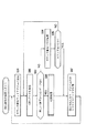
一方、ステップS155において、入力されたデータは、PCモードへの切り換え指示を示すものであると判断された場合、ステップS158に進み、PCモード処理が実行される。図21は、PCモード処理の詳細を説明するフローチャートである。ステップS171において、パーソナルコンピュータ4からのデータはあるか否かが判断される。ステップS171において、パーソナルコンピュータ4からのデータはないと判断された場合、ステップS172に進む。
On the other hand, if it is determined in step S155 that the input data indicates an instruction to switch to the PC mode, the process proceeds to step S158, and PC mode processing is executed. FIG. 21 is a flowchart for explaining the details of the PC mode processing. In step S171, it is determined whether there is data from the
ステップS172において、パーソナルコンピュータ4にGPS装置1に関係するアプリケーションが立ち上がっているか否かが判断される。この処理は、上述した図20のステップS156の処理と同様の処理なので、その説明は省略する。このように、どのようなモードであっても、GPS装置1に関するアプリケーションが立ち上がっているか否かを、常に判断することにより、パーソナルコンピュータ4およびGPS装置1の電力の無駄な消耗を防ぐことができる。
In step S172, it is determined whether an application related to the
ステップS172において、所定のアプリケーションが立ち上がっていると判断された場合、ステップS171に戻り、それ以降の処理が繰り返され(PCモードが継続され)、所定のアプリケーションが立ち上がっていないと判断された場合、ステップS157(図20)に進み、GPS装置1のパワーがオフにされる。
If it is determined in step S172 that the predetermined application is started, the process returns to step S171, and the subsequent processing is repeated (the PC mode is continued), and if it is determined that the predetermined application is not started, Proceeding to step S157 (FIG. 20), the power of the
一方、ステップS171において、パーソナルコンピュータ4からのデータがあると判断された場合、そのデータは、GPSモードへの切り換えを指示するコマンドであるか否かが判断される。ステップS171において、GPSモードへの切り替えを指示するコマンドであると判断された場合、ステップS174に進み、GPSモード処理が実行される。GPSモード処理は、図20に示したフローチャートの処理であるので、ステップS174における処理は、ステップS151(図20)に戻り、それ以降の処理が繰り替えされる処理である。
On the other hand, when it is determined in step S171 that there is data from the
ステップS173において、GPSモードへの切り替えを指示するコマンドではないと判断された場合、ステップS175に進み、パーソナルコンピュータ4からのコマンドの解析、実行処理が実行される。図22は、パーソナルコンピュータ4からのコマンドの解析、実行処理の詳細を説明するフローチャートである。
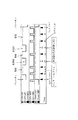
If it is determined in step S173 that the command is not a command for switching to the GPS mode, the process proceeds to step S175, and analysis and execution processing of the command from the
ステップS201において、リセットの指示か否かが判断され、リセットの指示であると判断された場合、ステップS202に進む。ステップS202において、リセット処理の実行される。GPS装置1は、上述したように、例えばスリープタイムやウェイクタイムといったパラメータが複数あり、ユーザが所望のパラメータ値を設定することができる。リセット処理では、そのように設定されたパラメータ値などが、デフォルトとして設定されていたパラメータ値に設定し直される。
In step S201, it is determined whether or not it is a reset instruction. If it is determined that the instruction is a reset instruction, the process proceeds to step S202. In step S202, reset processing is executed. As described above, the
ステップS201において、リセットの指示ではないと判断された場合、ステップS203に進み、USBからの電力に関するコマンドであるか否かが判断される。ステップS203において、USBからの電力に関するコマンドであると判断された場合、ステップS204に進み、そのコマンドに従い、USBからの電力がオンまたはオフの状態に設定される。 If it is determined in step S201 that the instruction is not a reset instruction, the process advances to step S203 to determine whether the command is related to the power from the USB. If it is determined in step S203 that the command is related to the power from the USB, the process proceeds to step S204, and the power from the USB is set to an on or off state according to the command.
ステップS203において、USBからの電力に関するコマンドではないと判断された場合、ステップS205に進み、アンテナ31の電力に関するコマンドであるか否かが判断される。ステップS205において、アンテナの電力に関するコマンドであると判断された場合、ステップS206に進み、そのコマンドに従い、アンテナへの電力の供給がオンまたはオフにされる。
If it is determined in step S203 that the command is not related to the power from the USB, the process proceeds to step S205 to determine whether the command is related to the power of the
ステップS205において、アンテナの電力に関するコマンドではないと判断された場合、ステップS207に進み、IDの出力指示であるか否かが判断される。ステップS207において、IDの出力指示であると判断された場合、ステップS208に進み、GPS装置1自身のIDが出力される。IDは、GPS装置1に固有に付けられた識別コードである。
If it is determined in step S205 that the command is not related to the power of the antenna, the process proceeds to step S207, and it is determined whether or not the command is an ID output instruction. If it is determined in step S207 that the instruction is to output an ID, the process proceeds to step S208, and the ID of the
ステップS207において、IDの出力指示ではないと判断された場合、ステップS209に進み、記憶部52からのダンプ指示であるか否かを判断する。ステップS209において、記憶部52からのダンプ指示であると判断された場合、ステップS210に進み、ダンプ処理が開始される。ダンプは途中で中止させることが可能である。そのため、ステップS209でランプ指示ではないと判断された場合、ステップS211に進み、ダンプ中止の指示であるか否かが判断される。
If it is determined in step S207 that the instruction is not an ID output instruction, the process advances to step S209 to determine whether the instruction is a dump instruction from the
ステップS211において、ダンプ中止の指示であると判断された場合、ステップS212に進み、ダンプ中止の処理が実行される。ステップS211において、ダンプ中止の指示ではないと判断された場合、ステップS213に進み、記憶部52からの読み出し指示であるか否かが判断される。ステップS213において、読み出し指示であると判断された場合、ステップS214に進み、コマンドに対応した所定のデータが読み出される。
If it is determined in step S211 that the instruction is to cancel dumping, the process proceeds to step S212, and dump canceling processing is executed. If it is determined in step S211 that the instruction is not a dump cancellation instruction, the process advances to step S213 to determine whether the instruction is a read instruction from the
ステップS213において、記憶部52からの読み出し指示ではないと判断された場合、ステップS215に進み、記憶部52へのデータの書き込み指示であるか否かが判断される。ステップS215において、記憶部52への書き込み指示であると判断された場合、ステップS216に進み、記憶部52へ、コマンドに対応したデータが書き込まれる。
If it is determined in step S213 that the instruction is not a read instruction from the
図22に示したコマンドの解析は、一例であり、その他にも、種々の処理を実行させるためのコマンドが用意されている。従って、図22に示したパーソナルコンピュータ4からのコマンドの解析、実行処理のフローチャートの処理は、それらのコマンドの内の、どのコマンドであるかを解析し、その解析結果に応じた処理を実行するためのものである。
The command analysis shown in FIG. 22 is an example, and other commands for executing various processes are prepared. Therefore, in the process of the flowchart of the analysis and execution process of the command from the
このような処理は、コマンドが入力される毎に行われる。従って、図22のフローチャートの処理が終了されると、図21のステップS171に戻り、それ以降の処理が繰り返される。さらに、図21のフローチャートの処理が終了されると、図20のステップS157に進み、GPS装置1のパワーがオフにされる。また、図20のフローチャートの処理が終了されると、図19ののフローチャートの処理も終了される。GPS装置1とパーソナルコンピュータ4がUSBにより接続されている時には、図19乃至図22のフローチャートを参照して説明したような処理が行われる。
Such processing is performed every time a command is input. Therefore, when the process of the flowchart of FIG. 22 is completed, the process returns to step S171 of FIG. 21, and the subsequent processes are repeated. Further, when the process of the flowchart of FIG. 21 is completed, the process proceeds to step S157 of FIG. 20, and the power of the
図22のフローチャートの処理におけるコマンドをパーソナルコンピュータ4から出力させるには、ユーザは、パーソナルコンピュータ4のディスプレイ19上に表示された画面から、所望のコマンドが出力されるような操作を行う必要がある。図23は、そのような操作画面の一例を示す図である。
In order to output a command in the processing of the flowchart of FIG. 22 from the
ディスプレイ19上には、GPS装置1の動作を決定するパラメータを操作(設定)するための設定ウィンドウ71が表示されている。設定ウィンドウ71は、主に、動作設定部72、メモリ設定部73、およびバッテリー設定部74の3部分から構成されている。動作設定部72は、ログの記録間隔を設定する間隔設定部75と、ウェイクアップの有効時間を設定する有効時間設定部76とから構成されている。
On the
メモリ設定部73は、メモリ(記憶部52)の容量が何パーセント以下になったら、そのことを知らせるアラーム表示させるかを設定する部分と、メモリに記憶されているログデータを全て消去(クリア)する時に操作されるクリアボタン77から構成されている。上述したように、記憶部52に記憶されたログデータは、ユーザの指示により、消去されない限り、記憶されつづけるので、記憶可能容量を確保するために、ユーザは、このクリアボタン77を定期的に操作し、記憶部52をクリアする必要がある。
The memory setting unit 73 erases (clears) all the log data stored in the portion for setting an alarm display to notify when the capacity of the memory (storage unit 52) falls below what percentage. It consists of a clear button 77 that is operated when As described above, the log data stored in the
バッテリー設定部74は、バッテリーの残量が何パーセント以下になったらアラーム表示を行うかを設定する為の部分である。設定ウィンドウ71の下部には、設定したパラメータを標準(デフォルト)の値に戻す時に操作されるボタン78−1、設定したパラメータで設定完了であるというときに操作されるボタン78−2、および、設定を行わずに、または設定したパラメータを反映させたくないときに、そして、設定ウィンドウ71を閉じたい時に操作されるボタン78−3の3個のボタンが備えられている。
The
各設定部におけるパラメータを設定するためには、ユーザは、カーソル79を、所望の部分にマウス16(図2)などを操作させることにより移動させ、クリックなどの所定の操作をすることにより行うことが可能である。例えば、ユーザがマウス16を用いて、カーソル79を間隔設定部75の部分に移動させ、クリックした場合、図24に示すように、プルダウンメニュー81が表示される。プルダウンメニュー81には、ログの記録の間隔として設定できる値が表示され、表示されきれていない部分を表示させるために操作されるスクロールバーが右側に表示されている。
In order to set parameters in each setting unit, the user moves the
例えば、ログの記録間隔として設定される値としては、1秒、3秒、5秒、10秒、30秒、1分、3分、5分、10分、30分、60分(1時間)の11通りである。勿論他の時間を設定できるように、プルダウンメニュー81に表示されるようにしても良い。ユーザは、ログを記録させる状況を考慮し、所望の時間を選択する。例えば、歩いているときにログを記憶させる時には、その移動速度は速くはないので、10分とか30分などの比較的長い時間(周期)を選択し、車で移動しているときにログを記憶させる時には、その移動速度は早いので、こまめに記録されるように30秒とか1分などの比較的短い時間を選択する。
For example, the value set as the log recording interval is 1 second, 3 seconds, 5 seconds, 10 seconds, 30 seconds, 1 minute, 3 minutes, 5 minutes, 10 minutes, 30 minutes, 60 minutes (1 hour) 11 ways. Of course, it may be displayed in the pull-
他のパラメータも同様の仕方により設定することが可能である。勿論、プルダウンメニュー81に表示された値のみを選択するのではなく、直接、設定部分にカーソル81を移動させ、表示されている数字を替えることも可能である。
Other parameters can be set in the same manner. Of course, instead of selecting only the value displayed in the pull-
設定されたパラメータに関するデータは、ボタン78−2が操作されることにより、パーソナルコンピュータ4からGPS装置1に対して出力される。この場合、GPS装置1においては、古いパラメータ値を新たに設定されたパラメータ値に書き換えるわけであるので、記憶部52への書き込み指示を受けることになる。すなわち、図22のフローチャートのステップS215において、記憶部52への書き込みの指示であると判断され、ステップS216に進み、パラメータ値の書き込み処理が実行される。
Data relating to the set parameters is output from the
このようなパーソナルコンピュータ4とGPS装置1との間でデータの授受が行われている際、何らかの原因でエラーが発生した場合、図25に示したようなエラーメッセージが、ディスプレイ19上に表示される。
When an error occurs for some reason when data is exchanged between the
設定ウィンドウ71は、図23に示したデザインに限らず、どのようなデザインでも良い。また、GPS装置1を操作、設定するための複数の設定ウィンドウが用意されており、特に図示はしないが、例えば、GPS装置1の記憶部52のログデータをパーソナルコンピュータ4のHDD18(図2)に記憶(ダンプ)させる時のウィンドウなどがある。ユーザがダンプさせる為の操作するウィンドウを開き、所定の操作し、ダンプを実行させた場合、図26に示したような、データ転送中であることを知らせるウィンドウがディスプレイ19上に表示される。
The setting window 71 is not limited to the design shown in FIG. Further, a plurality of setting windows for operating and setting the
図26に示したようなウィンドウが表示されているときに、ユーザがキャンセルボタンを操作した場合、GPS装置1においては、図22のステップS211の処理により、ダンプ中止の指示であると判断し、ステップS212において、ダンプ処理が中止される。その結果、図26に示したデータ転送中を示すウィンドウは表示されなくなる。
When the user operates the cancel button when the window as shown in FIG. 26 is displayed, the
このように、GPS装置1は、位置情報や時刻情報を含むログデータを記憶し、パーソナルコンピュータ4に、その記憶されたログデータを供給することが可能である。パーソナルコンピュータ4において、ユーザは、この供給されたログデータとデジタルカメラ2(図1)で撮像され、フロッピーディスク3に記憶された画像データとを関連付けて編集することができる。
Thus, the
デジタルカメラ2は、例えば、JEIDA(Japan Electronic Industry Development Association)が定義したデジタルカメラのフォーマット形式DCF(Design rule for Camera File)に基づき、撮影日時が、各画像データ毎に記録されるようになっている。即ち、図27に示すように、デジタルカメラ2で撮像された画像の画像ファイルは、主に、ヘッダーと画像データ本体から構成されており、そのヘッダーには、画像データ本体に記録されている画像に関するデータが記録され、その内の1つのデータとして、撮像日時が記録されている。
The
ここで、デジタルカメラ2により撮像された画像の撮像場所を特定する際の、パーソナルコンピュータ4の動作について、図28のフローチャートを参照して説明する。ステップS231において、パーソナルコンピュータ4はUSBを介して接続されているGPS装置1からログを読み出す。読み出されたログは、例えば、RAM13(図2)に記憶される。記憶される際、ログデータは、時刻順に昇順で配列されて記憶される。さらに、1つ1つのログデータに、0から始まるカウンタ値が付せられる。パーソナルコンピュータ4に記憶されたログの一例を、図29に示す。
Here, the operation of the
図29に示したログは、32個のログデータから構成されている。ログは、GPS装置1の電源がオンにされてからオフにされるまでに記録されたログデータの集まりであり、換言すれば、スタートフラグが1のログデータからエンドフラグが1までのログデータから構成されている。図29では、ログデータ本体の部分に記録されているデータのうち、時刻のみを示し、”10:18:00”乃至”10:33:30”まで、30秒ごとに、ログデータが記録された例を示している。また、このログデータ本体に記録されている時刻データを基に、時刻順に配列し、0乃至31のカウンタ値が付せられている。
The log shown in FIG. 29 is composed of 32 pieces of log data. The log is a collection of log data recorded from when the
ステップS232において、処理対象となる1画像データが読み込まれる。この読み込みは、まず、FDD17にセットされた、デジタルカメラ2により撮像された画像データが記録されているフロッピーディスク3(携帯用半導体メモリ5や通信を用いても良い)から、図27に示したようなデータ構造をもつ画像データがRAM13、または、HDD18に読み込まれ、記憶される。この際、フロッピーディスク3から、全ての画像データを読み出し、例えば、RAM13に記憶させた後、処理対象となる1画像データをRAM13から読み出すようにしても良いし、フロッピーディスク3から1画像データづつ読み出すようにしても良い。
In step S232, one image data to be processed is read. This reading is first shown in FIG. 27 from the floppy disk 3 (
ステップS233において、処理対象となるログデータのカウンタ値が初期値である0に設定される。ステップS234において、カウンタ値が全ログデータ数+1よりも小さいか否かが判断される。換言すれば、全てのログデータがステップS234以下の処理の処理対象となったか否かが判断される。この場合、カウンタ値が0に設定されたばかりであるので、カウンタ値は全ログデータ数+1より大きくはないと判断され、ステップS235に進む。 In step S233, the counter value of the log data to be processed is set to 0, which is an initial value. In step S234, it is determined whether or not the counter value is smaller than the total number of log data + 1. In other words, it is determined whether or not all log data has been subjected to processing in step S234 and subsequent steps. In this case, since the counter value has just been set to 0, it is determined that the counter value is not larger than the total number of log data + 1, and the process proceeds to step S235.
ステップS235において、プレログがカウンタ値に、ネクストログがカウンタ値+1に、それぞれ設定される。なお、プレログとネクストログは、それぞれ時刻的に隣り合うログデータ(カウンタ値が隣り合う)であり、プレログの方が、ネクストログより時刻的に1つ前の時刻を示すログデータとする。ステップS236において、プレログが示す時刻が撮影日時よりも以前であるか否かが判断される。すなわち、プレログが示す時刻が、ステップS232において読み込まれた、処理対象となっている画像データに含まれる撮影日時よりも以前を示す時刻であるか否かが判断される。 In step S235, the pre-log is set to the counter value, and the next log is set to the counter value + 1. Note that the prelog and the next log are log data that are adjacent in time (counter values are adjacent), and the prelog is log data that indicates the time immediately before the next log. In step S236, it is determined whether or not the time indicated by the pre-log is before the shooting date and time. That is, it is determined whether or not the time indicated by the prelog is a time that is earlier than the shooting date and time included in the image data to be processed, which is read in step S232.
ステップS236において、プレログが示す時刻が撮影日時以前であると判断された場合、ステップS237に進み、ネクストログが示す時刻が、撮影日時よりも後を示す時刻であるか否かが判断される。ネクストログが撮影日時よりも後を示す時刻ではないと判断された場合、ステップS238に進み、カウンタ値が1だけ加算され、その新たなカウンタ値のログデータに対して、ステップS234以下の処理が繰り返される。 If it is determined in step S236 that the time indicated by the pre-log is before the shooting date and time, the process proceeds to step S237, and it is determined whether or not the time indicated by the next log is a time that is later than the shooting date and time. If it is determined that the next log is not later than the shooting date and time, the process proceeds to step S238, where the counter value is incremented by 1, and the processing after step S234 is performed on the log data of the new counter value. Repeated.
一方、ステップS237において、ネクストログが示す時刻が撮影日時より後を示す時刻であると判断された場合、ステップS239に進む。ステップS239において、撮影場所の推測が行われる。ここで、図30を参照して撮影場所の推測の仕方について説明する。撮影日時が「10:32:40」である場合、まず、プレログのカウンタ値が0乃至28(時刻「10:18:00」乃至時刻「10:32:00」)のログデータまで、ステップS236の処理でプレログの示す時刻が撮影日時以前であると判断されるが、ステップS237において、ネクストログが示す時刻が撮影日時の後ではないと判断されるので、ステップS234乃至S238の処理が繰り返されることになる。 On the other hand, if it is determined in step S237 that the time indicated by the next log is a time after the shooting date and time, the process proceeds to step S239. In step S239, the shooting location is estimated. Here, a method of estimating the shooting location will be described with reference to FIG. If the shooting date and time is “10:32:40”, first, the log data of the pre-log counter value 0 to 28 (time “10:18:00” to time “10:32:00”) is processed in step S236. In step S237, it is determined that the time indicated by the pre-log is before the shooting date and time. However, in step S237, it is determined that the time indicated by the next log is not after the shooting date and time, so the processing in steps S234 to S238 is repeated. It will be.
そして、カウンタ値が29になったとき(即ち、プレログの示す時刻は「10:32:30」であり、ネクストログが示す時刻は「10:33:00」のとき)、ステップS236の処理で、プレログの示す時刻が撮影日時の時刻よりも以前であると判断され、ステップS237の処理で、ネクストログが示す時刻が撮影日時よりも後であると判断されるので、ステップS239の処理で撮影場所の推測が行われることになる。このような状態が、図30に示した状態である。即ち、撮影日時が2つのログデータの間に位置する状態である。 When the counter value reaches 29 (that is, the time indicated by the pre-log is “10:32:30” and the time indicated by the next log is “10:33:00”), the process of step S236 is performed. Since it is determined that the time indicated by the pre-log is before the time of the photographing date and time, and it is determined in step S237 that the time indicated by the next log is after the photographing date and time, the image is captured by the processing of step S239. The location will be guessed. Such a state is the state shown in FIG. That is, the shooting date and time is located between the two log data.
この場合、撮影日時が「10:32:40」であり、その前のログデータが示す時刻が「10:32:30」、その後のログデータが示す時刻が「10:33:00」である。図30に示したように、時間軸上に、2つのログデータと撮影日時を表す点を、それぞれプロットすると、撮影日時を示す点は、ログデータを示す2つの点を内分する点であると考えられる。そこで、撮影日時を示す点は、2つのログデータを示す点を1:2に内分する点であると考えると、2つのログデータの位置情報から、撮影日時の位置情報を推測することができる。 In this case, the shooting date is “10:32:40”, the time indicated by the previous log data is “10:32:30”, and the time indicated by the subsequent log data is “10:33:00”. . As illustrated in FIG. 30, when two log data and a point indicating the shooting date / time are plotted on the time axis, the point indicating the shooting date / time is a point that internally divides the two points indicating the log data. it is conceivable that. Therefore, when the point indicating the shooting date / time is considered to be a point dividing the point indicating the two log data into 1: 2, the position information of the shooting date / time can be estimated from the position information of the two log data. it can.
この場合、時刻「10:32:30」のログデータの位置情報は、「N42°32’35”」,「E135°12’20”」であり、時刻「10:33;00」のログデータの位置情報は、「N42°35’35”」,「E135°00’40”」である。撮影場所の北緯(N)は、2つのログデータの位置情報を、1対2に内分するということから、「N42°33’35”」と推測される。また、撮影場所の東経(E)は、2つのログデータの位置情報を、1対2に内分するといこうことから、「E135°04’20”」と推測される。ステップS239においては、このような推測により、撮影日時に対応する撮影場所が決定される。 In this case, the position information of the log data at time “10:32:30” is “N42 ° 32′35” ”and“ E135 ° 12′20 ”, and the log data at time“ 10:33:00 ”. The position information is “N42 ° 35′35 ″” and “E135 ° 00′40 ″”. The north latitude (N) of the shooting location is presumed to be “N42 ° 33′35” ”because the position information of the two log data is internally divided into one to two. Further, the east longitude (E) of the shooting location is assumed to be “E135 ° 04′20” ”because the position information of the two log data is divided into one to two. In step S239, the shooting location corresponding to the shooting date and time is determined based on such estimation.
なお、撮影日時と、ログデータが示す時刻とが一致する場合は、換言すると、内分比率が0:X(Xは、ログデータの記憶間隔に依存する値である)である場合は、そのログデータの位置情報が、処理対象となっている画像データの撮影場所のデータとして推測される。 If the shooting date and time indicated by the log data match, in other words, if the internal ratio is 0: X (X is a value depending on the storage interval of the log data) The position information of the log data is estimated as the shooting location data of the image data to be processed.
GPS装置1は、上述したように、1秒ごとにログデータを記憶する連続モードから、最大3600秒(1時間)間隔でログデータを記憶する間欠モードを選択できるようになっている。また、GPS装置1は、遮蔽物などが存在するところでは、正確に衛星からの信号を受信できないときがある(正確な位置情報を含むログデータを記憶できない時がある)。このようなことにより、間欠モードの場合や遮蔽物などで、衛星からの信号を受信できなかったために、画像データの撮影日時に対応する(一致する)位置情報を含むログデータが存在しない場合が想定される。このような場合に対処するため、上述したような処理により、撮影場所を推測する。
As described above, the
ステップS239において、撮影場所が推測(決定)されると、ステップS241において、その撮影場所のデータと処理対象となっている画像データとが、関連付けられ、例えば、HDD18に記憶される。
When the shooting location is estimated (determined) in step S239, the data of the shooting location and the image data to be processed are associated with each other and stored in, for example, the
一方、ステップS234において、カウンタ値が全ログデータ数+1よりも大きいと判断された場合、または、ステップS236において、プレログが示す時刻が撮影日時の時刻よりも以前ではないと判断された場合(すなわち、この場合、時刻の早い順に撮影日時と比較されていくのであるから、プレログが示す時刻が撮影日時の時刻よりも以前ではないと判断されるということは、まさに全てのログデータは、撮影日時より後の時刻を示しているということである)、ステップS240に進む。 On the other hand, if it is determined in step S234 that the counter value is greater than the total number of log data + 1, or if it is determined in step S236 that the time indicated by the pre-log is not earlier than the time of the photographing date and time (that is, In this case, since it is compared with the shooting date and time in order from the earliest time, it is determined that the time indicated by the pre-log is not earlier than the shooting date and time. It means that it indicates a later time), and the process proceeds to step S240.
ステップS240において、処理対象となっている画像データに対応する撮影場所が推測できないと判断され、ステップS241において、撮影場所が推測不可能であったことを示すデータと共に、画像データが記憶される。 In step S240, it is determined that the shooting location corresponding to the image data to be processed cannot be estimated. In step S241, image data is stored together with data indicating that the shooting location cannot be estimated.
上述した説明においては、撮影日時に近い時刻の2つのログデータを検索した後、撮影場所を推測するようにしたが、まず、撮影日時と一致する時刻のログデータを検索するステップを設け、一致するログデータが検索されない場合のみ、推測を行うようにしても良い。 In the above description, after searching for two log data at a time close to the shooting date and time, the shooting location is estimated. First, a step for searching log data at a time that matches the shooting date and time is provided. The estimation may be performed only when log data to be searched is not retrieved.
このようにして、撮影場所と関連付けられた画像データは、所定のアプリケーション上で、例えば、その位置情報に対応するデジタルマップ上の位置にサムネイル画像として表示されたり、位置情報を基に所定の地区毎にまとめられるといった編集がされる。また、画像データがデジタルマップ上に表示される際、その画像データに関連付けられている位置情報が、ユーザの指示により取得されたものである(マークボタン36が操作され際に記憶されたログデータからの位置情報である)場合、そのことを示す表示がされるなどしても良い。
In this way, the image data associated with the shooting location is displayed as a thumbnail image at a position on the digital map corresponding to the position information on a predetermined application, or a predetermined area based on the position information. Editing is done so that they are grouped together. Further, when the image data is displayed on the digital map, the position information associated with the image data is acquired by the user's instruction (the log data stored when the
また、ログデータは、画像データと関連付けて用いるばかりではなく、時間情報を基にソートし、そのソートされた順に位置情報をデジタルマップ上にプロットしていけば、その時歩いた歩行軌跡を作成することもできる。 Log data is used not only in association with image data, but also based on time information, and if the position information is plotted on the digital map in the sorted order, a walking trajectory walking at that time is created. You can also.
なお、上述した実施の形態においては、デジタルカメラ2で得られた静止画像を用いた場合を例に挙げて説明したが、デジタルビデオカメラなどで得られた動画像の画像データに対して本発明を適用できる。また、GPS以外に、GLONASS(Global Orbiting Navigation Satellite System)でも良い。
In the above-described embodiment, the case where a still image obtained by the
上述した一連の処理は、ハードウェアにより実行させることもできるが、ソフトウェアにより実行させることもできる。一連の処理をソフトウェアにより実行させる場合には、そのソフトウェアを構成するプログラムが、専用のハードウエアに組み込まれているコンピュータ、または、各種のプログラムをインストールすることで、各種の機能を実行することが可能な、例えば、汎用のパーソナルコンピュータなどに、プログラム格納媒体からインストールされる。 The series of processes described above can be executed by hardware, but can also be executed by software. When a series of processing is executed by software, a program constituting the software may execute various functions by installing a computer incorporated in dedicated hardware or various programs. For example, it is installed from a program storage medium in a general-purpose personal computer or the like.
ここでは、パーソナルコンピュータ4にインストールされ、パーソナルコンピュータ4によって実行可能な状態とされるプログラムを格納するプログラム格納媒体は、図31に示すように磁気ディスク131(フロッピーディスクを含む)、光磁気ディスク132(CD-ROM(Compact Disk-Read Only Memory),DVD(Digital Versatile Disk)を含む)、光磁気ディスク133(MD (Mini-Disk)を含む)、もしくは半導体メモリ134などよりなるパッケージメディア、または、プログラムが一時的若しくは永続的に格納されるROM112や記憶部118を構成するハードディスクなどにより構成される。プログラム格納媒体へのプログラム格納媒体へのプログラムの格納は、必要に応じてルータ、モデムなどのインタフェースを介して、ローカルエリアネットワーク、インターネット、デジタル衛星放送といった有線または無線の通信媒体を利用して行われる。
Here, the program storage medium for storing the program installed in the
なお、本明細書において、媒体により提供されるプログラムを記述するステップは、記載された順序に従って、時系列的に行われる処理は勿論、必ずしも時系列的に処理されなくとも、並列的あるいは個別に実行される処理をも含むものである。 In this specification, the steps for describing the program provided by the medium are performed in parallel or individually in accordance with the described order, as well as the processing performed in time series, not necessarily in time series. The process to be executed is also included.
また、本明細書において、システムとは、複数の装置により構成される装置全体を表すものである。 Further, in this specification, the system represents the entire apparatus constituted by a plurality of apparatuses.
1 GPS装置, 2 デジタルカメラ, 4 パーソナルコンピュータ, 31 アンテナ, 32 本体, 33 GPSランプ, 34 RECランプ, 35 POWERランプ, 36 マークボタン, 37 パワーボタン, 38 PC装着部, 39 ストラップ装着部, 40 電池蓋, 41 OPENボタン, 42 USBポート, 51 操作部, 52 記憶部, 53 制御部, 54 電力供給部, 61,62 スイッチ
DESCRIPTION OF
Claims (5)
外部装置からの電力を受け入れる受け入れ手段と
を備え、
取得した位置情報を内部に備える記憶装置に記憶させる第1のモードの場合、前記電力供給手段により供給される電力を用い、前記外部装置と接続され、前記記憶装置に記憶された前記位置情報を前記外部装置に出力する第2のモードの場合、前記電力供給手段による電力供給を停止して、前記受け入れ手段により受け入れている電力を用いる
情報処理装置。 Power supply means for supplying power from the attached battery;
Receiving means for receiving power from an external device, and
In the case of the first mode in which the acquired position information is stored in a storage device provided therein, the position information stored in the storage device is connected to the external device using the power supplied by the power supply means. In the second mode of outputting to the external device, the power supply by the power supply unit is stopped, and the power received by the reception unit is used.
請求項1に記載の情報処理装置。 The information processing apparatus according to claim 1, wherein the position information is GPS data.
請求項1に記載の情報処理装置。 When it is in the first mode when connected to the external device, the power supply from the power supply means is stopped, and when connected to the external device, the power supply from the power supply means The information processing apparatus according to claim 1, wherein when the computer is stopped, the stopped state is maintained.
取得した位置情報を内部に備える記憶装置に記憶させる第1のモードの場合、前記電力供給手段により供給される電力を用いて各部が動作するように制御し、
前記外部装置と接続され、前記記憶装置に記憶された前記位置情報を前記外部装置に出力する第2のモードの場合、前記電力供給手段による電力供給を停止して、前記受け入れ手段により受け入れている電力を用いて各部が動作するように制御する
情報処理方法。 In an information processing method for an information processing apparatus having power supply means for receiving power from a mounted battery and receiving means for receiving power from an external device,
In the case of the first mode in which the acquired position information is stored in a storage device provided therein, control is performed so that each unit operates using the power supplied by the power supply unit,
In the second mode, which is connected to the external device and outputs the position information stored in the storage device to the external device, the power supply by the power supply means is stopped and accepted by the accepting means An information processing method for controlling each unit to operate using electric power.
取得した位置情報を内部に備える記憶装置に記憶させる第1のモードの場合、前記電力供給手段により供給される電力を用いて各部が動作するように制御し、
前記外部装置と接続され、前記記憶装置に記憶された前記位置情報を前記外部装置に出力する第2のモードの場合、前記電力供給手段による電力供給を停止して、前記受け入れ手段により受け入れている電力を用いて各部が動作するように制御する
ステップを実行させるためのプログラムを記録したコンピュータ読み取り可能な記録媒体。 An information processing apparatus having power supply means for receiving power supply from a mounted battery and receiving means for receiving power from an external device,
In the case of the first mode in which the acquired position information is stored in a storage device provided therein, control is performed so that each unit operates using the power supplied by the power supply unit,
In the second mode, which is connected to the external device and outputs the position information stored in the storage device to the external device, the power supply by the power supply means is stopped and accepted by the accepting means A computer-readable recording medium storing a program for executing a step for controlling each unit to operate using electric power.
Priority Applications (1)
| Application Number | Priority Date | Filing Date | Title |
|---|---|---|---|
| JP2009189989A JP4760966B2 (en) | 2009-08-19 | 2009-08-19 | Information processing apparatus and method, and recording medium |
Applications Claiming Priority (1)
| Application Number | Priority Date | Filing Date | Title |
|---|---|---|---|
| JP2009189989A JP4760966B2 (en) | 2009-08-19 | 2009-08-19 | Information processing apparatus and method, and recording medium |
Related Parent Applications (1)
| Application Number | Title | Priority Date | Filing Date |
|---|---|---|---|
| JP26466099A Division JP4411703B2 (en) | 1999-09-17 | 1999-09-17 | Information processing apparatus and method, and recording medium |
Publications (2)
| Publication Number | Publication Date |
|---|---|
| JP2010015582A true JP2010015582A (en) | 2010-01-21 |
| JP4760966B2 JP4760966B2 (en) | 2011-08-31 |
Family
ID=41701584
Family Applications (1)
| Application Number | Title | Priority Date | Filing Date |
|---|---|---|---|
| JP2009189989A Expired - Fee Related JP4760966B2 (en) | 2009-08-19 | 2009-08-19 | Information processing apparatus and method, and recording medium |
Country Status (1)
| Country | Link |
|---|---|
| JP (1) | JP4760966B2 (en) |
Cited By (2)
| Publication number | Priority date | Publication date | Assignee | Title |
|---|---|---|---|---|
| WO2014137039A1 (en) * | 2013-03-07 | 2014-09-12 | Chang Hyun-Soo | Food waste treatment apparatus |
| US9030166B2 (en) | 2009-07-03 | 2015-05-12 | Nikon Corporation | Electronic device, and method controlling electronic power supply |
Citations (4)
| Publication number | Priority date | Publication date | Assignee | Title |
|---|---|---|---|---|
| JPH09163202A (en) * | 1995-12-07 | 1997-06-20 | Canon Inc | Electronic device |
| JPH1173247A (en) * | 1997-06-27 | 1999-03-16 | Canon Inc | I/o card and electronic equipment and electronic system and method for rising electronic equipment |
| JPH11175205A (en) * | 1997-12-15 | 1999-07-02 | Toshiba Corp | Computer system and power down control method therefor |
| JPH11212895A (en) * | 1998-01-30 | 1999-08-06 | Nec Corp | Consumption current control method and consumption current controller |
-
2009
- 2009-08-19 JP JP2009189989A patent/JP4760966B2/en not_active Expired - Fee Related
Patent Citations (4)
| Publication number | Priority date | Publication date | Assignee | Title |
|---|---|---|---|---|
| JPH09163202A (en) * | 1995-12-07 | 1997-06-20 | Canon Inc | Electronic device |
| JPH1173247A (en) * | 1997-06-27 | 1999-03-16 | Canon Inc | I/o card and electronic equipment and electronic system and method for rising electronic equipment |
| JPH11175205A (en) * | 1997-12-15 | 1999-07-02 | Toshiba Corp | Computer system and power down control method therefor |
| JPH11212895A (en) * | 1998-01-30 | 1999-08-06 | Nec Corp | Consumption current control method and consumption current controller |
Cited By (3)
| Publication number | Priority date | Publication date | Assignee | Title |
|---|---|---|---|---|
| US9030166B2 (en) | 2009-07-03 | 2015-05-12 | Nikon Corporation | Electronic device, and method controlling electronic power supply |
| US10128672B2 (en) | 2009-07-03 | 2018-11-13 | Nikon Corporation | Electronic device, and method controlling electronic power supply |
| WO2014137039A1 (en) * | 2013-03-07 | 2014-09-12 | Chang Hyun-Soo | Food waste treatment apparatus |
Also Published As
| Publication number | Publication date |
|---|---|
| JP4760966B2 (en) | 2011-08-31 |
Similar Documents
| Publication | Publication Date | Title |
|---|---|---|
| JP2001094916A (en) | Method and unit for information processing, and program storage medium | |
| JP2001091290A (en) | Device and method for information processing and program storage medium | |
| JP4525578B2 (en) | Imaging apparatus, GPS control method, and computer program | |
| TW201532437A (en) | Domain aware camera system | |
| US20130099971A1 (en) | Information processing apparatus, reception information server, information processing method, program, and recording medium | |
| JP2011141144A (en) | Electronic device, positioning device, information processing method, and program | |
| CN102540226A (en) | Information processing device, position recording method, and program | |
| JP4760966B2 (en) | Information processing apparatus and method, and recording medium | |
| JP4411703B2 (en) | Information processing apparatus and method, and recording medium | |
| JP2009080125A (en) | Device and method for recording positional information | |
| JP2001091628A (en) | Device and method for processing information, and program storage medium | |
| JP2001094917A (en) | Information processing unit | |
| JP2001091627A (en) | Device and method for processing information, and program storage medium | |
| JP2001094837A (en) | Information processor | |
| JP2001092569A (en) | Information processor, information processing method, and program storage medium | |
| JP2001091304A (en) | Apparatus and method for processing information, and program storing medium | |
| JP2001091620A (en) | Information processor | |
| JP2001091291A (en) | Device and method for information processing and program storage medium | |
| JP2001091629A (en) | Information processor | |
| JP2001091303A (en) | Apparatus and method for processing information and program storing medium | |
| JP2001091626A (en) | Device and method for processing information, and program storage medium | |
| JP2010281734A (en) | Positioning device, positioning method, program | |
| EP2905183B1 (en) | Electronic apparatus and control method thereof | |
| US20180373206A1 (en) | Electronic timepiece, time correction method, and storage medium | |
| JP2010061380A (en) | Data storage device |
Legal Events
| Date | Code | Title | Description |
|---|---|---|---|
| A131 | Notification of reasons for refusal |
Free format text: JAPANESE INTERMEDIATE CODE: A131 Effective date: 20110208 |
|
| A521 | Written amendment |
Free format text: JAPANESE INTERMEDIATE CODE: A523 Effective date: 20110404 |
|
| A01 | Written decision to grant a patent or to grant a registration (utility model) |
Free format text: JAPANESE INTERMEDIATE CODE: A01 Effective date: 20110510 |
|
| A61 | First payment of annual fees (during grant procedure) |
Free format text: JAPANESE INTERMEDIATE CODE: A61 Effective date: 20110523 |
|
| FPAY | Renewal fee payment (event date is renewal date of database) |
Free format text: PAYMENT UNTIL: 20140617 Year of fee payment: 3 |
|
| FPAY | Renewal fee payment (event date is renewal date of database) |
Free format text: PAYMENT UNTIL: 20140617 Year of fee payment: 3 |
|
| LAPS | Cancellation because of no payment of annual fees |