JP2010015359A - Numerical controller with tabular data for operating arbitrary axis - Google Patents
Numerical controller with tabular data for operating arbitrary axis Download PDFInfo
- Publication number
- JP2010015359A JP2010015359A JP2008174396A JP2008174396A JP2010015359A JP 2010015359 A JP2010015359 A JP 2010015359A JP 2008174396 A JP2008174396 A JP 2008174396A JP 2008174396 A JP2008174396 A JP 2008174396A JP 2010015359 A JP2010015359 A JP 2010015359A
- Authority
- JP
- Japan
- Prior art keywords
- axis
- command
- format data
- operating
- path table
- Prior art date
- Legal status (The legal status is an assumption and is not a legal conclusion. Google has not performed a legal analysis and makes no representation as to the accuracy of the status listed.)
- Granted
Links
Images


Classifications
-
- G—PHYSICS
- G05—CONTROLLING; REGULATING
- G05B—CONTROL OR REGULATING SYSTEMS IN GENERAL; FUNCTIONAL ELEMENTS OF SUCH SYSTEMS; MONITORING OR TESTING ARRANGEMENTS FOR SUCH SYSTEMS OR ELEMENTS
- G05B19/00—Programme-control systems
- G05B19/02—Programme-control systems electric
- G05B19/18—Numerical control [NC], i.e. automatically operating machines, in particular machine tools, e.g. in a manufacturing environment, so as to execute positioning, movement or co-ordinated operations by means of programme data in numerical form
- G05B19/4155—Numerical control [NC], i.e. automatically operating machines, in particular machine tools, e.g. in a manufacturing environment, so as to execute positioning, movement or co-ordinated operations by means of programme data in numerical form characterised by programme execution, i.e. part programme or machine function execution, e.g. selection of a programme
-
- Y—GENERAL TAGGING OF NEW TECHNOLOGICAL DEVELOPMENTS; GENERAL TAGGING OF CROSS-SECTIONAL TECHNOLOGIES SPANNING OVER SEVERAL SECTIONS OF THE IPC; TECHNICAL SUBJECTS COVERED BY FORMER USPC CROSS-REFERENCE ART COLLECTIONS [XRACs] AND DIGESTS
- Y02—TECHNOLOGIES OR APPLICATIONS FOR MITIGATION OR ADAPTATION AGAINST CLIMATE CHANGE
- Y02P—CLIMATE CHANGE MITIGATION TECHNOLOGIES IN THE PRODUCTION OR PROCESSING OF GOODS
- Y02P90/00—Enabling technologies with a potential contribution to greenhouse gas [GHG] emissions mitigation
- Y02P90/02—Total factory control, e.g. smart factories, flexible manufacturing systems [FMS] or integrated manufacturing systems [IMS]
Abstract
Description
本発明は、工作機械を制御する数値制御装置に関する。特に、テーブルに記憶されたデータに基づいて各軸を制御する数値制御装置に関する。 The present invention relates to a numerical controller for controlling a machine tool. In particular, the present invention relates to a numerical control device that controls each axis based on data stored in a table.
NCプログラムのブロックによる指令ではなく、時間、軸位置、或いは主軸位置を基準にした軸の位置を設定したテーブル形式データ(パステーブル)を順次読み出しながら各軸を駆動する機能(パステーブル運転機能)を持った数値制御装置は既に公知である。このパステーブル運転機能により、加工プログラムに囚われない自由な工具の動作が可能になり、加工時間の短縮や、加工の高度化を実現できる。 Function to drive each axis while sequentially reading out table format data (path table) that sets the position of the axis based on time, axis position, or spindle position instead of command by NC program block (pass table operation function) A numerical control device having the above is already known. With this pass table operation function, it is possible to operate the tool freely without being constrained by the machining program, so that the machining time can be shortened and the machining can be advanced.
例えば、特許文献1には、時間毎又は回転角度毎に対する可動軸の位置を数値制御データとして記憶しておき、時間又は回転角度を監視し、記憶した時間又は回転角度に達する毎に、可動軸に対応する数値制御データを出力するようにした技術が開示されている。
For example, in
また、特許文献2には、基準位置に対するX軸、Z軸の指令位置を記憶するデータテーブルを設けておき、基準パルスをカウントするカウンタの値にオーバライド値をかけて基準位置を求めて、該基準位置に基づいて、データテーブルに記憶されたX軸、Z軸の指令位置を出力してX軸、Z軸を同期制御することにより、データテーブルに記憶されたデータによって駆動制御する場合でもオーバライドが掛けられるようにし、更には、指令位置間を直線的に接続するか、2次関数接続、3次関数接続等を指令できると共に、補助機能も指令できる技術が開示されている。
Further,
図1に示される大型ガントリ機械のように、X軸とA軸でガントリを駆動する場合には、A軸とX軸は同じ経路パターンをとるように制御される。この大型ガントリ機械にテーブル形式データ(パステーブル)によって運転する場合には、X軸とA軸のテーブル形式データ(パステーブル)は同じテーブル形式データ(パステーブル)を用意する必要がある。 When the gantry is driven by the X axis and the A axis as in the large gantry machine shown in FIG. 1, the A axis and the X axis are controlled to take the same path pattern. When operating this large gantry machine with table format data (pass table), it is necessary to prepare the same table format data (pass table) for the X-axis and A-axis table format data (pass table).
背景技術で説明したテーブル形式データ(パステーブル)による運転では、時間、軸位置、あるいは主軸位置を基準にした軸の位置とその軸名称を設定したテーブル形式データ(パステーブル)をそれぞれの軸ごとに作成する必要がある。そして、作成したテーブル形式データは、数値制御装置内のメモリに予め格納しておく必要がある。 In operation using the table format data (path table) explained in the background art, the table format data (path table) that sets the axis position and axis name based on the time, axis position, or spindle position is set for each axis. Need to be created. The created table format data needs to be stored in advance in a memory in the numerical controller.
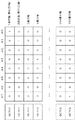
そのため、それぞれの軸に対して、図1に示すような同じ経路パターンとなる指令の場合でも(図2、図3参照)、時間、軸位置、あるいは主軸位置を基準にした軸の位置を設定した、軸名称が異なるだけのパステーブル形式データ(パステーブル)をX軸とA軸のそれぞれの軸ごとに作成する必要があった(図4、図5参照)。 Therefore, for each axis, even in the case of a command having the same path pattern as shown in FIG. 1 (see FIGS. 2 and 3), the position of the axis based on time, axis position, or spindle position is set. Thus, it is necessary to create path table format data (path table) having different axis names for each of the X axis and the A axis (see FIGS. 4 and 5).
図6に、テーブル形式データ(パステーブル)を起動するNCプログラムの例を示す。M700の指令がパステーブル運転起動用Mコードを表す。Q1000の指令が1000番のパステーブルを表す。図6のM700Q1000の指令が実行されることにより、X軸用の1000番のパステーブル(図4参照)とA軸用の1000番のパステーブル(図5参照)が起動され、X軸とA軸が動作する。 FIG. 6 shows an example of an NC program for starting table format data (path table). The command of M700 represents the M code for starting the path table operation. The command of Q1000 represents the 1000th path table. When the command of M700Q1000 in FIG. 6 is executed, the 1000th path table for X axis (see FIG. 4) and the 1000th path table for A axis (see FIG. 5) are activated, and the X axis and A The axis moves.
図4に示されるX軸用のパステーブルに見られるように、パステーブルには、「パステーブル番号」として「1000番」、「軸」として「X軸」が指定されている。そして、「時間または主軸位置」と「位置」とを対応させて指定している。図5にはA軸用のパステーブルが記載されている。「時間または主軸位置」と「位置」のデータは図4のX軸用のパステーブルと同じである。このため、同じデータを2つのテーブル形式データ(パステーブル)として数値制御装置に記憶する必要があり、記憶させるためのメモリ容量が増大するという課題があった。 As can be seen from the X-axis path table shown in FIG. 4, “1000” is designated as the “path table number” and “X-axis” is designated as the “axis” in the path table. Then, “time or spindle position” and “position” are specified in correspondence with each other. FIG. 5 shows a path table for the A axis. The data of “time or spindle position” and “position” is the same as the X-axis path table of FIG. For this reason, it is necessary to store the same data as two table format data (path table) in the numerical controller, and there is a problem that the memory capacity for storing the data increases.
そこで本発明は、任意の1軸を動作させるためのテーブル形式データ(パステーブル)を作成し、そのテーブル形式データ(パステーブル)を任意の軸で共用できるようにし、テーブル形式データ(パステーブル)の容量を削減することを目的とする。 Therefore, the present invention creates table format data (path table) for operating any one axis, and allows the table format data (path table) to be shared by any axis. Table format data (path table) The purpose is to reduce the capacity.
本願の請求項1に係る発明は、時間、軸位置、あるいは主軸位置を基準とし、基準となる時間、軸あるいは主軸の位置と、前記基準となる軸あるいは主軸とは別の軸あるいは主軸の位置とを対応させたテーブル形式データをメモリに格納しておき、前記基準となる時間、軸あるいは主軸の位置と、前記基準となる軸あるいは主軸とは別の軸あるいは主軸の位置を順次読み出し、前記基準となる時間、軸あるいは主軸の位置に同期して前記別の軸あるいは主軸の位置を制御する数値制御装置において、1つのテーブル形式データを、任意の軸を動作させるためのテーブル形式データとして記憶した記憶手段と、前記任意の軸を動作させるためのテーブル形式データを起動する手段と、前記任意の軸を動作させるためのテーブル形式データにより動作する軸を指定する手段と、を備えたことを特徴とする任意の軸を動作させるテーブル形式データを有する数値制御装置である。
The invention according to
請求項2に係る発明は、前記任意の軸を動作させるためのテーブル形式データを起動する手段は、NCプログラム指令、信号の入力、あるいは他のテーブル形式データでの指令であることを特徴とする請求項1に記載の任意の軸を動作させるテーブル形式データを有する数値制御装置である。
The invention according to
請求項3に係る発明は、前記任意の軸を動作させるためのテーブル形式データにより動作する軸を指定する手段は、NCプログラム指令、信号の入力、あるいは前記任意の軸を動作させるためのテーブル形式データを起動する前記他のテーブル形式データでの指令であることを特徴とする請求項2に記載の任意の軸を動作させるテーブル形式データを有する数値制御装置である。
According to a third aspect of the present invention, the means for designating an axis to be operated based on table format data for operating the arbitrary axis is an NC program command, a signal input, or a table format for operating the arbitrary axis. 3. The numerical control apparatus having table format data for operating an arbitrary axis according to
本発明により、任意の1軸を動作させるためのテーブル形式データ(パステーブル)を作成し、そのテーブル形式データ(パステーブル)を任意の軸で共用できるようになり、テーブル形式データ(パステーブル)の容量を削減することができる。 According to the present invention, table format data (path table) for operating any one axis can be created, and the table format data (path table) can be shared by any axis. Table format data (path table) The capacity of can be reduced.
以下、本発明の実施形態を、図面を用いて説明する。
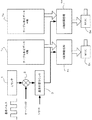
図7は、本発明の任意の軸を動作させるテーブル形式データを有する工作機械を駆動する一実施形態の数値制御装置10の要部ブロック図である。CPU11は数値制御装置10を全体的に制御するプロセッサである。CPU11は、ROM12に格納されたシステムプログラムを、バス20を介して読み出し、該システムプログラムに従って数値制御装置全体を制御する。RAM13には一時的な計算データや表示データ及びLDC/MDIユニット70を介してオペレータが入力した各種データが格納される。SRAMメモリ14は図示しないバッテリでバックアップされ、数値制御装置10の電源がオフされても記憶状態が保持される不揮発性メモリとして構成される。SRAMメモリ14中には、インタフェース15を介して読み込まれた加工プログラムやLCD/MDIユニット70を介して入力された加工プログラム等が記憶される。LCDは液晶表示装置を意味する。さらに、前述した、任意の軸を動作させるテーブル形式データが予め格納されている。また、ROM12には、加工プログラムの作成及び編集のために必要とされる編集モードの処理や自動運転のための処理を実施するための各種システムプログラムが予め書き込まれている。
Hereinafter, embodiments of the present invention will be described with reference to the drawings.
FIG. 7 is a block diagram of a main part of a
インタフェース15は、数値制御装置10と外部機器との接続を可能とするものである。PMC(プログラマブル・マシン・コントローラ)16は、数値制御装置10に内蔵されたシーケンスプログラムで工作機械の補助装置にI/Oユニット17を介して信号を出力し制御する。また、工作機械の本体に配備された操作盤の各種スイッチ等の信号を受け、必要な信号処理をした後、CPU11に渡す。
The
各軸のサーボ制御部30,31はCPU11からの各軸の移動指令量を受けて、各軸の指令をサーボアンプ40,41に出力する。サーボアンプ40,41はこの指令を受けて、各軸のサーボモータ5x,5aを駆動する。各軸のサーボモータ5x,5aは、位置・速度検出器を内蔵し、この位置・速度検出器からの位置、速度フィードバック信号をサーボ制御部30,31にフィードバックし、位置・速度のフィードバック制御を行う。なお、図7では位置・速度のフィードバックについては記載を省略している。
The
また、スピンドル制御部60は主軸指令を受け、スピンドルアンプ61にスピンドル速度信号を出力する。スピンドルアンプ61はスピンドル速度信号を受けて、主軸を駆動する主軸モータ62を指令された回転速度で回転させる。ポジションコーダ63は、主軸の回転に同期して帰還パルス(基準パルス)及び1回転信号をスピンドル制御部60にフィードバックし、速度制御を行う。この帰還パルス及び1回転信号は、スピンドル制御部60を介してCPU11によって読取られる。帰還パルス(基準パルス)はRAM13に設けられたカウンタで計数される。また、カウンタは、主軸指令パルスによっても計数される場合がある。図7に示される数値制御装置10は制御軸としてA軸とX軸とを有しているが、制御軸としては、さらに増加してもよいことは勿論である。
Further, the
ここで、本発明の理解を容易にするために、各軸それぞれテーブル形式データを用意し、それらを用いて運転する従来技術のパステーブル運転の概要を、図8を用いて説明する。
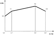
パステーブル運転をおこなう数値制御装置は、X軸用パステーブルTx、A軸用パステーブルTaを備えている。X軸用パステーブルTx、A軸用パステーブルTaは、例えば図4、図5に示されるもので、横軸は時間、軸位置、あるいは主軸位置を基準とした基準値である。縦軸はX軸、A軸の基準値に対する位置である。
Here, in order to facilitate understanding of the present invention, an outline of a conventional path table operation in which table format data is prepared for each axis and the operation is performed using these data will be described with reference to FIG.
The numerical control device that performs the path table operation includes an X-axis path table Tx and an A-axis path table Ta. The X-axis path table Tx and the A-axis path table Ta are shown in FIGS. 4 and 5, for example, and the horizontal axis is a reference value based on time, axis position, or spindle position. The vertical axis is the position relative to the reference values of the X axis and A axis.
主軸に取り付けたポジションコーダからのパルス又は主軸の指令パルス又は基準とする外部パルス発生器からの時間を基準とする基準パルスが、カウンタ1に入力され計数される。このカウンタ1の計数値にオーバライド手段に設定されている倍率が乗算器2で乗じられ基準位置カウンタ3に格納される。この基準位置カウンタ3は、パステーブル運転機能が指令された時点、又は、パステーブル運転機能が指令された後の最初の基準軸からの1回転信号によりリセットされる。
A pulse from a position coder attached to the spindle, a command pulse of the spindle, or a reference pulse based on time from an external pulse generator as a reference is input to the
この基準位置カウンタ3の値が基準位置としてパステーブル運転補間処理部4x,4aに入力され、X軸用パステーブルTx、A軸用パステーブルTaを参照して基準値に対するX軸、A軸の指令位置を求め、処理周期での移動量を求め該移動量を指令として各制御軸モータ5x,5aに出力し、X軸,A軸を基準位置に合わせて同期運転するものである。
The value of the
次に、本発明である任意の軸を動作させるテーブル形式データを有する数値制御装置について説明する。図9では、図8に示した従来技術と同様の要素は同じ符号を用いている。図9は、N番のテーブル形式データをX軸とA軸の移動制御のために共通に使用するテーブル形式データを用いた数値制御装置の実施形態である。図1に示されるように、A軸とX軸とは同期して動作する。そこで、A軸とX軸とを動作させるためのテーブル形式データを共用する。ここでは、N番のテーブル形式データをX軸とA軸の共通のテーブル形式データとして用いている。N番のテーブル形式データは、例えば図13に示される軸指定が無い任意の軸を動作させるためのパステーブルである。 Next, a numerical controller having table format data for operating an arbitrary axis according to the present invention will be described. In FIG. 9, the same reference numerals are used for the same elements as those in the prior art shown in FIG. FIG. 9 shows an embodiment of a numerical control apparatus using table format data in which the Nth table format data is commonly used for movement control of the X axis and the A axis. As shown in FIG. 1, the A axis and the X axis operate in synchronization. Therefore, the table format data for operating the A axis and the X axis is shared. Here, the Nth table format data is used as the common table format data for the X axis and the A axis. The N-th table format data is, for example, a path table for operating an arbitrary axis without axis designation shown in FIG.
主軸に取り付けたポジションコーダからのパルス又は主軸の指令パルス又は基準とする外部パルス発生器からの時間を基準とする基準パルスが、カウンタ1に入力され計数される。このカウンタ1の計数値にオーバライド手段に設定されている倍率が乗算器2で乗じられ基準位置カウンタ3に格納される。
A pulse from a position coder attached to the spindle, a command pulse of the spindle, or a reference pulse based on time from an external pulse generator as a reference is input to the
この基準位置カウンタ3の値が基準位置としてパステーブル運転補間処理部4x,4aに入力され、N番のテーブル形式データを参照して基準値に対するX軸、A軸の指令位置を求め、処理周期での移動量を求め、該移動量を指令として各制御軸モータ5x,5aに出力し、X軸,A軸を基準値に合わせて同期運転するものである。
The value of the
次に、図10、図11、及び図12を用いて、図7において所定周期毎に実行されるパステーブル補間処理を含む本発明の処理を説明する。ここでは、任意の軸としてX軸とA軸とを例にとって説明する。
図10は、各軸のパステーブル起動フラグを設定する処理を示すアルゴリズムを示す。以下、各ステップに従って説明する。本発明においては、各軸のパステーブル運転の起動指令として、NCプログラムの指令、外部信号による指令、またはテーブル形式データによる指令を用いている。なお、NCプログラムの指令、外部信号による指令は、図10において説明されている。テーブル形式データによる指令は、図11、図12において説明されている。
Next, the processing of the present invention including the path table interpolation processing executed at predetermined intervals in FIG. 7 will be described with reference to FIG. 10, FIG. 11, and FIG. Here, the X axis and the A axis will be described as examples of arbitrary axes.
FIG. 10 shows an algorithm showing processing for setting a path table activation flag for each axis. Hereinafter, it demonstrates according to each step. In the present invention, an NC program command, a command by an external signal, or a command by table format data is used as a start command for the path table operation of each axis. The NC program command and the command by the external signal are illustrated in FIG. The command based on the table format data is described in FIGS.
プロセッサ(CPU11)は、ステップS1で外部信号によるパステーブル運転指令ありか否か判断し(ステップS1)、パステーブル運転指令でなければNCプログラムのブロックを読み込み(ステップS2)、読み込んだブロックはパステーブル運転の指令か否か判断し(ステップS3)、パステーブル運転の指令でない場合にはブロックの指令を実行する(ステップS6)。
一方、ステップS1、S3でパステーブル運転指令と判断された場合にはステップS4に進み、指令された軸のパステーブル起動フラグを1に設定し(ステップS4)、次に、パステーブル運転指令により指令され起動するパステーブルの番号をレジスタに格納する(ステップS5)。
The processor (CPU 11) determines whether or not there is a path table operation command by an external signal in step S1 (step S1). If it is not a path table operation command, the NC program block is read (step S2). It is determined whether or not it is a table operation command (step S3), and if it is not a path table operation command, a block command is executed (step S6).
On the other hand, if it is determined in step S1 or S3 that the command is a path table operation command, the process proceeds to step S4 where the commanded axis path table activation flag is set to 1 (step S4). The number of the path table to be commanded and activated is stored in the register (step S5).
図11は、図9におけるX軸補間処理を示すフローチャートである。
CPU11(図7参照)は、X軸のパステーブル運転を起動するフラグは「1」にセットされているか否か判断し(ステップSX1)、フラグが「1」にセットされていなければパステーブル運転処理を終了し、フラグが「1」にセットされていれば順次更新される基準位置Lを読み込む(ステップSX2)。基準位置Lは、「時間、軸位置、あるいは主軸位置」である。なお、パステーブル運転を開始する際には、基準位置Lはリセットされる(図9に示される基準位置カウンタ3のリセットを参照)。
FIG. 11 is a flowchart showing the X-axis interpolation processing in FIG.
The CPU 11 (see FIG. 7) determines whether or not the flag for starting the X-axis pass table operation is set to “1” (step SX1). If the flag is not set to “1”, the pass table operation is performed. The process is terminated, and if the flag is set to “1”, the reference position L that is sequentially updated is read (step SX2). The reference position L is “time, axis position, or spindle position”. Note that when starting the pass table operation, the reference position L is reset (see the reset of the
次に、パステーブルから指令基準位置及び指令位置のデータを読み出す(ステップSX3)。そして、指令基準位置があるか否か判断し(ステップSX4)、指令基準位置がない場合には、X軸のパステーブル起動フラグを0に設定し(ステップSX10)、パステーブル運転を終了する。一方、指令基準位置がある場合には、指令基準位置に対して任意の軸を動作させるためのパステーブルを起動させる指令か否か判断し(ステップSX5)、パステーブルを起動する指令でない場合にはステップSX7へ移行し、パステーブルを起動する指令である場合には、パステーブル運転する軸のパステーブル起動フラグを1に設定し、起動するパステーブルの番号を保存する(ステップSX6)。 Next, the command reference position and command position data are read from the path table (step SX3). Then, it is determined whether or not there is a command reference position (step SX4). If there is no command reference position, the X-axis path table activation flag is set to 0 (step SX10), and the path table operation is terminated. On the other hand, if there is a command reference position, it is determined whether or not the command is for starting a path table for operating an arbitrary axis with respect to the command reference position (step SX5). Shifts to step SX7, and if it is a command to activate the path table, the path table activation flag of the axis for which the path table is operated is set to 1, and the number of the path table to be activated is stored (step SX6).
次に、指定されたパステーブルのデータを用いてパステーブル補間処理を実行し、所定周期毎補間処理がなされ処理結果である移動指令は対応するサーボ制御部(図7参照)に出力され(ステップSX7)、基準位置Lを読取り(ステップSX8)、読取った基準位置Lが指令基準位置(ステップSX3で読み込んだ指令基準位置)に達したか否か判断し(ステップSX9)、達していなければ、ステップSX7〜ステップSX9の処理を所定周期毎実行する。達していれば、ステップSX3へ戻り、処理を継続する。 Next, the path table interpolation process is executed using the specified path table data, the interpolation process is performed every predetermined period, and the movement command which is the process result is output to the corresponding servo control unit (see FIG. 7) (step). SX7), the reference position L is read (step SX8), and it is determined whether or not the read reference position L has reached the command reference position (command reference position read in step SX3) (step SX9). Steps SX7 to SX9 are executed at predetermined intervals. If it has reached, the process returns to step SX3 to continue the process.
ここで、ステップSX1で判断されるX軸のパステーブル運転を起動するパステーブル起動フラグが「1」に設定される場合について説明すると、以下の4つの場合にパステーブル起動フラグが「1」に設定される。
(1)従来技術のパステーブル運転と同様に、X軸のパステーブル(テーブル形式データTx)を起動する指令が指令された場合。
(2)NCプログラム指令により、任意の軸を動作させるためのパステーブル(テーブル形式データ)を起動する指令が指令され、任意の軸を動作させるためのパステーブル(テーブル形式データ)により動作する軸をX軸と指令された場合。
(3)信号により、任意の軸を動作させるためのテーブル形式データを起動させる指令が指令され、任意の軸を動作させるためのパステーブル(テーブル形式データ)により動作する軸をX軸と指定された場合。
(4)A軸のパステーブル(テーブル形式データTa)により、任意の軸を動作させるためのパステーブル(テーブル形式データ)を起動させる指令が指令され、任意の軸を動作させるためのパステーブル(テーブル形式データ)により動作させる軸をX軸と指令された場合。
Here, the case where the path table activation flag for activating the X-axis path table operation determined in step SX1 is set to “1” will be described. In the following four cases, the path table activation flag is set to “1”. Is set.
(1) When a command for starting the X-axis path table (table format data Tx) is issued, as in the conventional path table operation.
(2) A command for starting a path table (table format data) for operating an arbitrary axis is commanded by an NC program command, and an axis operated by a path table (table format data) for operating an arbitrary axis Is designated as the X axis.
(3) An instruction to start table format data for operating an arbitrary axis is instructed by a signal, and an axis operating by a path table (table format data) for operating an arbitrary axis is designated as an X axis. If
(4) A command for starting a path table (table format data) for operating an arbitrary axis is commanded by the A axis path table (table format data Ta), and a path table (for operating an arbitrary axis) When the X axis is commanded as the axis to be operated according to the table format data).
次に、図12は、図9におけるA軸補間処理を示すフローチャートである。
CPU11(図7参照)は、A軸のパステーブル運転を起動するフラグは「1」にセットされているか否か判断し(ステップSA1)、フラグが「1」にセットされていなければパステーブル運転処理を終了し、フラグが「1」にセットされていれば順次更新される基準位置Lを読み込む(ステップSA2)。基準位置Lは、「時間、軸位置、あるいは主軸位置」である。なお、パステーブル運転を開始する際には、基準位置Lはリセットされる(図9に示される基準位置カウンタ3のリセットを参照)。
Next, FIG. 12 is a flowchart showing the A-axis interpolation process in FIG.
The CPU 11 (see FIG. 7) determines whether or not the flag for starting the A-axis pass table operation is set to “1” (step SA1). If the flag is not set to “1”, the pass table operation is performed. The processing is terminated, and if the flag is set to “1”, the reference position L that is sequentially updated is read (step SA2). The reference position L is “time, axis position, or spindle position”. Note that when starting the pass table operation, the reference position L is reset (see the reset of the
次に、パステーブルから指令基準位置と指令位置とを読み出す(ステップSA3)。そして、指令基準位置があるか否か判断し(ステップSA4)、指令基準位置がない場合には、A軸のパステーブル起動フラグを0に設定し(ステップSA10)、パステーブル運転を終了する。一方、指令基準位置がある場合には、指令基準位置に対して任意の軸を動作させるためのパステーブルを起動させる指令か否か判断し(ステップSA5)、パステーブルを起動する指令でない場合にはステップSX7へ移行し、パステーブルを起動する指令である場合には、パステーブル運転する軸のパステーブル起動フラグを1に設定し、起動するパステーブルの番号を保存する(ステップSA6)。 Next, the command reference position and the command position are read from the path table (step SA3). Then, it is determined whether or not there is a command reference position (step SA4). If there is no command reference position, the A-axis path table activation flag is set to 0 (step SA10), and the path table operation is terminated. On the other hand, if there is a command reference position, it is determined whether it is a command for starting a path table for operating an arbitrary axis with respect to the command reference position (step SA5). Shifts to step SX7, and if it is a command to activate the path table, the path table activation flag of the axis for which the path table is operated is set to 1, and the number of the path table to be activated is stored (step SA6).
次に、指定されたパステーブルのデータを用いてパステーブル補間処理を実行し、所定周期毎補間処理がなされ処理結果である移動指令は対応するサーボ制御部(図7参照)に出力され(ステップSA7)、基準位置Lを読取り(ステップSA8)、読取った基準位置Lが指令基準位置(ステップSA3で読み込んだ指令基準位置)に達したか否か判断し(ステップSA9)、達していなければ、ステップSA7〜ステップSA9の処理を所定周期毎実行する。達していれば、ステップSA3へ戻り、処理を継続する。 Next, the path table interpolation process is executed using the specified path table data, the interpolation process is performed every predetermined period, and the movement command which is the process result is output to the corresponding servo control unit (see FIG. 7) (step). SA7), the reference position L is read (step SA8), and it is determined whether or not the read reference position L has reached the command reference position (command reference position read in step SA3) (step SA9). Steps SA7 to SA9 are executed at predetermined intervals. If so, the process returns to step SA3 to continue the process.
ここで、A軸のパステーブル運転を起動するパステーブル起動フラグが「1」に設定される場合について説明すると、以下の4つの場合にパステーブル起動フラグが「1」に設定される。
(1)従来技術のパステーブル運転と同様に、A軸のパステーブル(テーブル形式データTa)を起動する指令が指令された場合。
(2)NCプログラム指令により、任意の軸を動作させるためのパステーブル(テーブル形式データ)を起動する指令が指令され、任意の軸を動作させるためのパステーブル(テーブル形式データ)により動作する軸をA軸と指令された場合。
(3)信号により、任意の軸を動作させるためのテーブル形式データを起動させる指令が指令され、任意の軸を動作させるためのパステーブル(テーブル形式データ)により動作する軸をA軸と指定された場合。
(4)X軸のパステーブル(テーブル形式データTx)により、任意の軸を動作させるためのパステーブル(テーブル形式データ)を起動させる指令が指令され、任意の軸を動作させるためのパステーブル(テーブル形式データ)により動作させる軸をA軸と指令された場合。
Here, the case where the path table activation flag for activating the A-axis path table operation is set to “1” will be described. In the following four cases, the path table activation flag is set to “1”.
(1) When a command for starting the A-axis path table (table format data Ta) is issued, as in the conventional path table operation.
(2) A command for starting a path table (table format data) for operating an arbitrary axis is commanded by an NC program command, and an axis operated by a path table (table format data) for operating an arbitrary axis Is commanded as A axis.
(3) An instruction to start table format data for operating an arbitrary axis is instructed by a signal, and an axis to be operated by a path table (table format data) for operating an arbitrary axis is designated as an A axis. If
(4) A command for starting a path table (table format data) for operating an arbitrary axis is commanded by the X axis path table (table format data Tx), and a path table (for operating an arbitrary axis) When the axis to be operated is commanded as the A axis according to the table format data).
図13に示されるように、軸指定がない任意の1軸を動作させるためのテーブル形式データを作成し、1つのテーブル形式データを任意の軸を動作させるためのテーブル形式データとする。図13は、図4や図5の軸指定のあるパステーブルと比較すると理解できるように、「3番のパステーブル」のように軸指定されていず、任意の軸を動作させるためのパステーブルを示している。図13に示される軸指定のないパステーブルを、任意の軸で共用することによりパステーブルを格納するためのメモリ容量を削減できる。なお、これ以降、パステーブルの「時間または主軸位置」を指令基準位置、「位置」を指令位置という。 As shown in FIG. 13, table format data for operating an arbitrary axis without axis designation is created, and one table format data is used as table format data for operating an arbitrary axis. FIG. 13 is a path table for operating an arbitrary axis without specifying an axis, such as “No. 3 path table”, as can be understood by comparing with the path table with an axis specified in FIGS. 4 and 5. Is shown. By sharing the path table without axis designation shown in FIG. 13 with any axis, the memory capacity for storing the path table can be reduced. Hereinafter, “time or spindle position” of the path table is referred to as a command reference position, and “position” is referred to as a command position.
図14は、図13に示されるような任意の軸を動作させるためのテーブル形式データを、NCプログラム指令によって起動する実施形態を示している。M800の指令がパステーブル運転起動用Mコードを表す。Q3の指令が任意の軸を動作させるための3番のパステーブルを表す。R12がX軸(1軸目)とA軸(2軸目)を表す。X軸(1軸目)を動作させる場合はR1を指令し、A軸(2軸目)を動作させる場合はR2を指令する。図14のNCプログラムでは、M800のQ3R12の指令が実行されることにより、任意の軸を動作させるための3番のパステーブル(図13参照)が起動され、X軸とA軸が動作することになる。 FIG. 14 shows an embodiment in which table format data for operating an arbitrary axis as shown in FIG. 13 is activated by an NC program command. The command of M800 represents the M code for starting the path table operation. The command of Q3 represents the third path table for operating an arbitrary axis. R12 represents the X axis (first axis) and the A axis (second axis). When operating the X axis (first axis), R1 is commanded, and when operating the A axis (second axis), R2 is commanded. In the NC program of FIG. 14, when the command of Q3R12 of M800 is executed, the third path table (see FIG. 13) for operating an arbitrary axis is activated, and the X axis and the A axis operate. become.
ここで、図11、図12で説明したパステーブル運転を図13に示されるパステーブル、図14に示されるNCプログラムに従って実行すると、プロセッサ(CPU11)は、図10に示されるフローチャートに従って、図14に示される加工プログラムのブロックを実行(ステップS6)していき、「M800Q3R12」のブロックで、パステーブル運転の指令と判断し、指令された軸(この例では、1がX軸、2がA軸として)のパステーブル起動フラグを1に設定する(ステップS4)。そして、起動するパステーブル(この例では3番のパステーブル)の番号を保存する(ステップS5) Here, when the path table operation described in FIGS. 11 and 12 is executed according to the path table shown in FIG. 13 and the NC program shown in FIG. 14, the processor (CPU 11) follows the flowchart shown in FIG. Is executed (step S6), and the block of “M800Q3R12” is determined to be a command for path table operation, and the commanded axis (in this example, 1 is the X axis, 2 is the A The path table activation flag as an axis is set to 1 (step S4). Then, the number of the path table to be activated (the third path table in this example) is stored (step S5).
次に、まず、指令基準位置である「時間または主軸位置」のL0が読み出され、これと共に指令されている指令位置である位置X0が読み出される(ステップSX3)。ステップSX3は指令基準位置であるからステップSX7に進む。初回目は補間処理を行うための次の指令基準位置および指令位置のデータが読み込まれていないので、ステップSX8に進む。ステップSX8で基準位置Lを読込み、指令基準位置に到達したか判断するが、初回目は基準位置Lと指令基準位置L0とは一致しているので、ステップSX3に戻り、処理を継続する。 Next, L0 of “time or spindle position” that is a command reference position is read, and a command position X0 that is commanded together with this is read (step SX3). Since step SX3 is the command reference position, the process proceeds to step SX7. At the first time, since the next command reference position and command position data for performing the interpolation processing are not read, the process proceeds to step SX8. In step SX8, the reference position L is read to determine whether or not the command reference position has been reached, but since the reference position L and the command reference position L0 coincide with each other for the first time, the process returns to step SX3 and the processing is continued.
次に、指令基準位置である「時間または主軸位置」のL1,X1の処理、次にL2,X2の処理、次にL3,X3の処理と行う。指令基準位置L3,指令位置X3までの補間処理が終了すると、ステップSX3で読み込む指令基準位置が無いことから、ステップSX4での判断から、ステップSX10に移行しX軸のパステーブル起動フラグを「0」に設定し、パステーブル運転を停止する。
また、A軸もX軸と同じ3番のパステーブルを用いてパステーブル運転がなされる。処理の内容は上述のX軸と同様であるので、説明の記載を省略する。なお、図11のステップSX7の移動指令,図12のステップSA7の移動指令はそれぞれ対応するサーボ制御部に出力される。なお、X軸とA軸とで基準位置L、パステーブルとも同じであるので、X軸とA軸とで移動指令を共有する構成してもよい。例えば、図11のステップSX7での移動指令をX軸のサーボ制御部のみではなくA軸のサーボ制御部にも入力するようにしてもよい。
Next, the processing of L1 and X1 of the “time or spindle position” as the command reference position, the processing of L2 and X2, and then the processing of L3 and X3 are performed. When the interpolation processing to the command reference position L3 and the command position X3 is completed, there is no command reference position to be read in step SX3. Therefore, from the determination in step SX4, the process proceeds to step SX10 and the X-axis path table activation flag is set to “0”. ”To stop the pass table operation.
In addition, the A-axis is also operated by using the same third pass table as the X-axis. Since the content of the process is the same as that of the above-mentioned X axis, description of the description is omitted. Note that the movement command in step SX7 in FIG. 11 and the movement command in step SA7 in FIG. 12 are output to the corresponding servo control units. Since the reference position L and the path table are the same for the X axis and the A axis, a movement command may be shared between the X axis and the A axis. For example, the movement command in step SX7 in FIG. 11 may be input not only to the X-axis servo control unit but also to the A-axis servo control unit.
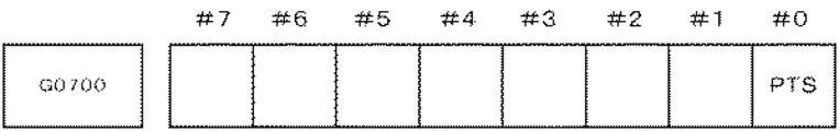
図15は任意の軸を動作させるためのパステーブルを起動する信号の例である。この起動する信号を「G0700」のコードで表す。このコード名は適宜設定してよい。図15では「G0700」は8ビットの信号からなっており、「♯0」で示されるビットでPTS信号を表す。パステーブルを起動する際にはこのPTSを「1」とする。なお、PTSは、パステーブルスタートのことを意味する。この信号「G0700」は、工作機械の本体に配備されている操作盤(図示を省略)の各種スイッチ等からの信号をPMC(プログラマブルマシンコントローラ)で受け、工作機械のシーケンス制御(主に、主軸回転、工具交換、機械操作盤制御)で必要な信号処理をした後、数値制御装置に出力される信号である。 FIG. 15 is an example of a signal for starting a path table for operating an arbitrary axis. This activation signal is represented by a code “G0700”. This code name may be set as appropriate. In FIG. 15, “G0700” is an 8-bit signal, and the bit indicated by “# 0” represents the PTS signal. When the path table is activated, this PTS is set to “1”. PTS means a path table start. This signal “G0700” receives signals from various switches and the like of an operation panel (not shown) provided in the machine tool body by a PMC (programmable machine controller), and controls the sequence of the machine tool (mainly, the spindle This signal is output to the numerical control device after necessary signal processing is performed in rotation, tool change, machine operation panel control).
図15で示される信号PTS<G700.0>が”1”になると、図16で示される信号PTN1〜PTN8<G0701.0〜G0701.7>で指定されたパステーブル番号のパステーブルが起動され、そして、図18で示される信号PTA1〜PTA8<G0702.0〜G0702.7>で指定された軸番号の軸が動作する。 When the signal PTS <G700.0> shown in FIG. 15 becomes “1”, the path table having the path table number designated by the signals PTN1 to PTN8 <G0701.0 to G0701.7> shown in FIG. 16 is activated. Then, the axis having the axis number designated by the signals PTA1 to PTA8 <G0702.0 to G0702.7> shown in FIG. 18 operates.
図16は任意の軸を動作させるためのパステーブルを指定する信号を示している。この信号を「G0701」で表す。G0701は8ビットの信号であり、各ビットの指定により図17に示されるように1番目のテーブルから255番目のテーブルを指定することができる。なお信号「G0701」のビット数を増加すれば指定可能なパステーブルの数を増加することは可能である。 FIG. 16 shows a signal for designating a path table for operating an arbitrary axis. This signal is represented by “G0701”. G0701 is an 8-bit signal, and by specifying each bit, the 255th table can be specified from the first table as shown in FIG. If the number of bits of the signal “G0701” is increased, the number of path tables that can be specified can be increased.
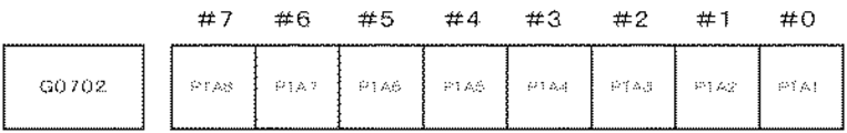
図18は任意の軸を動作させるためのパステーブルに対して、動作させる軸の軸番号を指定する信号を示している。この信号を「G0702」のコードで表す。「G0702」は8ビットの信号であり、各ビットによって任意の軸を動作させるためのパステーブルに対して動作させる軸の軸番号を指定することができる。 FIG. 18 shows a signal for designating an axis number of an axis to be operated with respect to a path table for operating an arbitrary axis. This signal is represented by a code “G0702”. “G0702” is an 8-bit signal, and the axis number of the axis to be operated with respect to the path table for operating an arbitrary axis can be designated by each bit.
図19に示されるように、信号G0702で任意の軸を動作させるためのパステーブルに対して、動作させる軸の軸番号を指定する。X軸とA軸を動作させる場合には、G0702.0=1、G0702.1=1に設定する。 As shown in FIG. 19, the axis number of the axis to be operated is designated with respect to the path table for operating an arbitrary axis by the signal G0702. When the X axis and the A axis are operated, G0702.0 = 1 and G0702.1 = 1 are set.
図20は、任意の軸を動作させるためのパステーブルを起動し、そのパステーブルにより動作する軸を指定する他のパステーブルを示している。Q3の指令が任意の軸を動作させるための3番のパステーブルを表す。F12がX軸(1番目)とA軸(2番目)を表す。X軸(1番目)を動作させる場合はF1を指令し、A軸を動作させる場合はF2(2番目)を指令する。図20のL2の時間または主軸位置の基準値で、Q3F12の指令が実行されることにより、任意の軸を動作させるための3番目のパステーブル(図13参照)が起動され、X軸とA軸が動作する。この実施形態の場合には、X軸は7000番のパステーブルのデータに基づく移動量と3番のパステーブルのデータに基づく移動量が加算された動作となる。 FIG. 20 shows another path table for starting a path table for operating an arbitrary axis and designating an axis to be operated by the path table. The command of Q3 represents the third path table for operating an arbitrary axis. F12 represents the X axis (first) and the A axis (second). When operating the X axis (first), F1 is commanded, and when operating the A axis, F2 (second) is commanded. When the command of Q3F12 is executed at the time L2 in FIG. 20 or the reference value of the spindle position, the third path table (see FIG. 13) for operating any axis is activated, and the X axis and A The axis moves. In the case of this embodiment, the X-axis is an operation in which the movement amount based on the data of the 7000th path table and the movement amount based on the data of the 3rd path table are added.
1 カウンタ
2 乗算器
3 基準位置カウンタ
4x,4a パステーブル運転補間処理部
5x,5a 各制御軸モータ
10 数値制御装置
1
Claims (3)
1つのテーブル形式データを、任意の軸を動作させるためのテーブル形式データとして記憶した記憶手段と、
前記任意の軸を動作させるためのテーブル形式データを起動する手段と、
前記任意の軸を動作させるためのテーブル形式データにより動作する軸を指定する手段と、を備えたことを特徴とする任意の軸を動作させるテーブル形式データを有する数値制御装置。 Memory of table format data that associates time, axis or spindle position with reference time, axis position or spindle position, and axis or spindle position different from the reference axis or spindle And sequentially reading out the reference time, the position of the axis or spindle, and the position of the axis or spindle different from the reference axis or spindle, and the reference time, position of the axis or spindle In the numerical control device for controlling the position of the another axis or the main axis in synchronization with
Storage means for storing one table format data as table format data for operating an arbitrary axis;
Means for activating table format data for operating the arbitrary axis;
A numerical controller having table format data for operating an arbitrary axis, comprising: means for designating an axis to be operated by table format data for operating the arbitrary axis.
Priority Applications (4)
| Application Number | Priority Date | Filing Date | Title |
|---|---|---|---|
| JP2008174396A JP4554697B2 (en) | 2008-07-03 | 2008-07-03 | Numerical control device having table format data for operating arbitrary axis |
| US12/472,567 US8155779B2 (en) | 2008-07-03 | 2009-05-27 | Numerical controller with tabular data for operating arbitrary axes |
| DE102009026570A DE102009026570A1 (en) | 2008-07-03 | 2009-05-29 | Numerical controller with tabular data for the operation of any axis |
| CN2009101427183A CN101620430B (en) | 2008-07-03 | 2009-06-02 | Numerical controller with tabular data for operating arbitrary axes |
Applications Claiming Priority (1)
| Application Number | Priority Date | Filing Date | Title |
|---|---|---|---|
| JP2008174396A JP4554697B2 (en) | 2008-07-03 | 2008-07-03 | Numerical control device having table format data for operating arbitrary axis |
Publications (2)
| Publication Number | Publication Date |
|---|---|
| JP2010015359A true JP2010015359A (en) | 2010-01-21 |
| JP4554697B2 JP4554697B2 (en) | 2010-09-29 |
Family
ID=41396916
Family Applications (1)
| Application Number | Title | Priority Date | Filing Date |
|---|---|---|---|
| JP2008174396A Active JP4554697B2 (en) | 2008-07-03 | 2008-07-03 | Numerical control device having table format data for operating arbitrary axis |
Country Status (4)
| Country | Link |
|---|---|
| US (1) | US8155779B2 (en) |
| JP (1) | JP4554697B2 (en) |
| CN (1) | CN101620430B (en) |
| DE (1) | DE102009026570A1 (en) |
Cited By (4)
| Publication number | Priority date | Publication date | Assignee | Title |
|---|---|---|---|---|
| CN104656548A (en) * | 2013-11-20 | 2015-05-27 | 发那科株式会社 | Numerical Control Device Having Function Of Simultaneously Executing Plurality Of Commands Using Data In Table Format |
| CN105022350A (en) * | 2015-07-14 | 2015-11-04 | 江苏新瑞重工科技有限公司 | System and method for recovering reference point of each axis of numerical control machine tool |
| JP2016122399A (en) * | 2014-12-25 | 2016-07-07 | ファナック株式会社 | Numerical controller operating with table-format data |
| US20160313720A1 (en) * | 2015-04-21 | 2016-10-27 | Fanuc Corporation | Numerical controller operating based on tabular data |
Families Citing this family (5)
| Publication number | Priority date | Publication date | Assignee | Title |
|---|---|---|---|---|
| JP5800888B2 (en) * | 2013-12-24 | 2015-10-28 | ファナック株式会社 | Numerical control device with smoothing function for operation by table format data |
| JP5820000B2 (en) * | 2014-02-21 | 2015-11-24 | ファナック株式会社 | Numerical control device that operates with tabular data |
| JP6325488B2 (en) * | 2015-06-30 | 2018-05-16 | ファナック株式会社 | Numerical control device that operates with tabular data |
| JP6346206B2 (en) * | 2016-01-14 | 2018-06-20 | ファナック株式会社 | Numerical control device having block time display means |
| EP3690573B1 (en) * | 2019-01-30 | 2021-08-18 | Siemens Aktiengesellschaft | Control of a machine tool |
Citations (2)
| Publication number | Priority date | Publication date | Assignee | Title |
|---|---|---|---|---|
| JP2001306150A (en) * | 2000-04-18 | 2001-11-02 | Nippon Pulse Motor Co Ltd | Operation setting table which sets operation state of shaft control motor and control board which controls the shaft control motor by the operation setting table |
| JP2003303005A (en) * | 2002-04-09 | 2003-10-24 | Fanuc Ltd | Numerical control device |
Family Cites Families (15)
| Publication number | Priority date | Publication date | Assignee | Title |
|---|---|---|---|---|
| JPS59177604A (en) * | 1983-03-28 | 1984-10-08 | Fanuc Ltd | Numerical control method |
| JP3220588B2 (en) * | 1994-01-28 | 2001-10-22 | 三菱電機エンジニアリング株式会社 | Positioning device |
| JP4738585B2 (en) * | 2000-10-26 | 2011-08-03 | シチズンホールディングス株式会社 | Machining program graph display method and apparatus therefor |
| US7119805B2 (en) * | 2001-02-20 | 2006-10-10 | Canon Kabushiki Kaisha | Three-dimensional CAD attribute information presentation |
| US6988018B2 (en) * | 2001-12-26 | 2006-01-17 | Eames John D | System and method for analyzing controlling forming sections of a paper machine in operation |
| CN1630838B (en) * | 2002-02-07 | 2010-05-26 | 三菱电机株式会社 | Numeric control method and numeric control system |
| DE10343809B4 (en) | 2002-09-27 | 2018-03-15 | Siemens Aktiengesellschaft | Method and apparatus for numerical control |
| US7003373B2 (en) * | 2002-09-27 | 2006-02-21 | Siemens Aktiengesellschaft | Method and device for numerical control |
| CN100537145C (en) * | 2005-01-20 | 2009-09-09 | 沃尔特机器制造有限责任公司 | Apparatus and method for machine tool control |
| EP1712967B1 (en) * | 2005-04-13 | 2008-10-01 | Fanuc Ltd | Numerical controller |
| JP4282631B2 (en) * | 2005-04-20 | 2009-06-24 | ファナック株式会社 | Numerical control device that operates with tabular data |
| JP4299805B2 (en) * | 2005-04-25 | 2009-07-22 | ファナック株式会社 | Numerical control device that performs tool compensation using table format data |
| JP4044105B2 (en) * | 2005-04-25 | 2008-02-06 | ファナック株式会社 | Numerical control device having function of switching operation means for each system |
| JP4692488B2 (en) * | 2005-12-26 | 2011-06-01 | 三菱電機株式会社 | Numerical control device and numerical control machine tool |
| JP4928536B2 (en) * | 2006-03-03 | 2012-05-09 | 本田技研工業株式会社 | Machine Tools |
-
2008
- 2008-07-03 JP JP2008174396A patent/JP4554697B2/en active Active
-
2009
- 2009-05-27 US US12/472,567 patent/US8155779B2/en active Active
- 2009-05-29 DE DE102009026570A patent/DE102009026570A1/en not_active Ceased
- 2009-06-02 CN CN2009101427183A patent/CN101620430B/en active Active
Patent Citations (2)
| Publication number | Priority date | Publication date | Assignee | Title |
|---|---|---|---|---|
| JP2001306150A (en) * | 2000-04-18 | 2001-11-02 | Nippon Pulse Motor Co Ltd | Operation setting table which sets operation state of shaft control motor and control board which controls the shaft control motor by the operation setting table |
| JP2003303005A (en) * | 2002-04-09 | 2003-10-24 | Fanuc Ltd | Numerical control device |
Cited By (9)
| Publication number | Priority date | Publication date | Assignee | Title |
|---|---|---|---|---|
| CN104656548A (en) * | 2013-11-20 | 2015-05-27 | 发那科株式会社 | Numerical Control Device Having Function Of Simultaneously Executing Plurality Of Commands Using Data In Table Format |
| JP2015099553A (en) * | 2013-11-20 | 2015-05-28 | ファナック株式会社 | Numerical control device including function for simultaneously executing multiple commands with table format data |
| US9696712B2 (en) | 2013-11-20 | 2017-07-04 | Fanuc Corporation | Numerical control device having function of simultaneously executing plurality of commands using data in table format |
| CN104656548B (en) * | 2013-11-20 | 2017-12-26 | 发那科株式会社 | Possesses the numerical control device of the operation based on sheet form data |
| JP2016122399A (en) * | 2014-12-25 | 2016-07-07 | ファナック株式会社 | Numerical controller operating with table-format data |
| US9964943B2 (en) | 2014-12-25 | 2018-05-08 | Fanuc Corporation | Numerical controller operating based on tabular data |
| US20160313720A1 (en) * | 2015-04-21 | 2016-10-27 | Fanuc Corporation | Numerical controller operating based on tabular data |
| US10073433B2 (en) * | 2015-04-21 | 2018-09-11 | Fanuc Corporation | Numerical controller operating based on tabular data |
| CN105022350A (en) * | 2015-07-14 | 2015-11-04 | 江苏新瑞重工科技有限公司 | System and method for recovering reference point of each axis of numerical control machine tool |
Also Published As
| Publication number | Publication date |
|---|---|
| CN101620430A (en) | 2010-01-06 |
| CN101620430B (en) | 2011-12-28 |
| US8155779B2 (en) | 2012-04-10 |
| DE102009026570A1 (en) | 2010-01-07 |
| JP4554697B2 (en) | 2010-09-29 |
| US20100004760A1 (en) | 2010-01-07 |
Similar Documents
| Publication | Publication Date | Title |
|---|---|---|
| JP4554697B2 (en) | Numerical control device having table format data for operating arbitrary axis | |
| JP3671020B2 (en) | Numerical controller | |
| JP4382123B2 (en) | Numerical control device having control mode switching function | |
| JP4282631B2 (en) | Numerical control device that operates with tabular data | |
| JP4233540B2 (en) | Numerical control device that drives each axis motor using table format data | |
| JP5172990B2 (en) | Numerical control device with operation function based on table format data | |
| JP4044105B2 (en) | Numerical control device having function of switching operation means for each system | |
| JP2012093989A (en) | Correction method at the time of feed shaft reversal | |
| US20160026169A1 (en) | Numerical controller supporting left-handed coordinate system | |
| JP2008234319A (en) | Numerical controller capable of executing g-code command in path table operation | |
| JP2009122852A (en) | Numerical controller for storing operating history during path table operation | |
| WO1994017459A1 (en) | Method of execution of nc machining program | |
| JPH103307A (en) | Numerical controller | |
| JPH03196310A (en) | Display system for numerical controller | |
| JP2008269483A (en) | Numerical controller | |
| JP6162655B2 (en) | Numerical control device that operates with tabular data | |
| JP4116640B2 (en) | Numerical control device with multi-system control function | |
| JP2004114176A (en) | Numerical controller | |
| JP4282632B2 (en) | Numerical control device that operates with tabular data | |
| JP2006344041A (en) | Tool locus plotting method and apparatus | |
| JP2008130013A (en) | Numerical control device | |
| WO2023053349A9 (en) | Numerical control device | |
| JP3203927B2 (en) | Production management device | |
| JPH04252307A (en) | Interactive numerical controller | |
| JP4275981B2 (en) | Axis feed control device for machine tools |
Legal Events
| Date | Code | Title | Description |
|---|---|---|---|
| A871 | Explanation of circumstances concerning accelerated examination |
Free format text: JAPANESE INTERMEDIATE CODE: A871 Effective date: 20100127 |
|
| A975 | Report on accelerated examination |
Free format text: JAPANESE INTERMEDIATE CODE: A971005 Effective date: 20100205 |
|
| A977 | Report on retrieval |
Free format text: JAPANESE INTERMEDIATE CODE: A971007 Effective date: 20100409 |
|
| A131 | Notification of reasons for refusal |
Free format text: JAPANESE INTERMEDIATE CODE: A131 Effective date: 20100413 |
|
| A521 | Written amendment |
Free format text: JAPANESE INTERMEDIATE CODE: A523 Effective date: 20100531 |
|
| TRDD | Decision of grant or rejection written | ||
| A01 | Written decision to grant a patent or to grant a registration (utility model) |
Free format text: JAPANESE INTERMEDIATE CODE: A01 Effective date: 20100622 |
|
| A01 | Written decision to grant a patent or to grant a registration (utility model) |
Free format text: JAPANESE INTERMEDIATE CODE: A01 |
|
| A61 | First payment of annual fees (during grant procedure) |
Free format text: JAPANESE INTERMEDIATE CODE: A61 Effective date: 20100714 |
|
| FPAY | Renewal fee payment (event date is renewal date of database) |
Free format text: PAYMENT UNTIL: 20130723 Year of fee payment: 3 |
|
| R150 | Certificate of patent or registration of utility model |
Free format text: JAPANESE INTERMEDIATE CODE: R150 Ref document number: 4554697 Country of ref document: JP Free format text: JAPANESE INTERMEDIATE CODE: R150 |