JP2010014959A - Lens barrel - Google Patents

Lens barrel Download PDF

Info

Publication number
JP2010014959A
JP2010014959A JP2008174689A JP2008174689A JP2010014959A JP 2010014959 A JP2010014959 A JP 2010014959A JP 2008174689 A JP2008174689 A JP 2008174689A JP 2008174689 A JP2008174689 A JP 2008174689A JP 2010014959 A JP2010014959 A JP 2010014959A
Authority
JP
Japan
Prior art keywords
optical axis
lens barrel
group
axis direction
fixed cylinder
Prior art date
Legal status (The legal status is an assumption and is not a legal conclusion. Google has not performed a legal analysis and makes no representation as to the accuracy of the status listed.)
Granted
Application number
JP2008174689A
Other languages
Japanese (ja)
Other versions
JP5090274B2 (en
Inventor
Hiroshi Nomura
博 野村
Current Assignee (The listed assignees may be inaccurate. Google has not performed a legal analysis and makes no representation or warranty as to the accuracy of the list.)
Hoya Corp
Original Assignee
Hoya Corp
Priority date (The priority date is an assumption and is not a legal conclusion. Google has not performed a legal analysis and makes no representation as to the accuracy of the date listed.)
Filing date
Publication date
Application filed by Hoya Corp filed Critical Hoya Corp
Priority to JP2008174689A priority Critical patent/JP5090274B2/en
Priority to US12/263,694 priority patent/US7965933B2/en
Priority to TW097142460A priority patent/TWI418913B/en
Priority to KR1020080110449A priority patent/KR101249869B1/en
Priority to CN 200810175556 priority patent/CN101430414B/en
Priority to GB0820515A priority patent/GB2454780B/en
Priority to DE102008056601A priority patent/DE102008056601A1/en
Publication of JP2010014959A publication Critical patent/JP2010014959A/en
Priority to US13/453,385 priority patent/USRE44171E1/en
Application granted granted Critical
Publication of JP5090274B2 publication Critical patent/JP5090274B2/en
Expired - Fee Related legal-status Critical Current
Anticipated expiration legal-status Critical

Links

Images

Landscapes

  • Lens Barrels (AREA)

Abstract

<P>PROBLEM TO BE SOLVED: To provide a lens barrel capable of reliably protecting a biasing means which is swingable around an axis orthogonal to a plane parallel with an optical axis to bias an optical element-holding member without depending on the shape of a stationary barrel member. <P>SOLUTION: The lens barrel includes: the optical element-holding member for holding an optical element constituting a photographing optical system, which is moveable in an optical axis direction; the stationary barrel member surrounding the photographing optical system; the biasing means which is positioned on the outside of the stationary barrel member, is swingable around the axis orthogonal to the optical axis, and biases the optical element-holding member in the optical axis direction through a force applied portion extending in a radial direction from the center of swing; and a protective wall member which is provided as a separate member from the stationary barrel member, and fixed to the stationary barrel member to create an accommodation space for the biasing means between an outer surface of the stationary barrel member and the protective wall member. <P>COPYRIGHT: (C)2010,JPO&INPIT

Description

本発明はレンズ鏡筒に関し、特に、光軸方向に進退する光学要素に対する付勢手段の保護構造に関する。   The present invention relates to a lens barrel, and more particularly, to a protection structure for a biasing means for an optical element that advances and retreats in the optical axis direction.

レンズ鏡筒においては、光軸方向に移動可能な光学要素の保持部材に対して、その駆動機構の一部の機能を担わせたり、駆動機構におけるバックラッシュを取ったり、あるいは位置を安定させたりする目的で、光軸方向への付勢力が与えられることが多い。この種の付勢手段は、駆動機構の負荷軽減や動作精度向上などの観点から、光学要素の移動量あたりの荷重の変動幅が小さい方が好ましく、大型の付勢手段を用いることで、荷重の変動幅を小さくすることが可能である。例えば、付勢手段が引張ばねや圧縮ばねである場合、その伸縮方向に長いばねを用いれば荷重の変動幅を小さくできる。しかし、小型化が要求されているレンズ鏡筒においては、光軸方向に長い引張ばねや圧縮ばねを採用することが難しいという問題があった。これを解決するものとして、光学系の光軸と平行な平面に対して略直交する軸を中心に、径方向へ延出された着力部(付勢部)を揺動させるタイプの付勢手段が提案されている(特許文献1)。この付勢手段の具体的態様として、トーションばねや、揺動するレバー部材と付勢ばねの組み合わせが想定されている。
特願2007−291656号
In the lens barrel, the holding member of the optical element movable in the optical axis direction is responsible for a part of the drive mechanism, takes backlash in the drive mechanism, or stabilizes the position. For this purpose, an urging force in the optical axis direction is often applied. This type of urging means preferably has a smaller fluctuation range of the load per moving amount of the optical element from the viewpoint of reducing the load on the driving mechanism and improving the operation accuracy. It is possible to reduce the fluctuation range of. For example, when the biasing means is a tension spring or a compression spring, the load fluctuation range can be reduced by using a spring that is long in the expansion and contraction direction. However, a lens barrel that is required to be downsized has a problem that it is difficult to employ a tension spring or a compression spring that is long in the optical axis direction. In order to solve this problem, an urging means of a type that swings an urging portion (biasing portion) extending in the radial direction around an axis substantially orthogonal to a plane parallel to the optical axis of the optical system. Has been proposed (Patent Document 1). As a specific mode of the biasing means, a torsion spring or a combination of a swinging lever member and a biasing spring is assumed.
Japanese Patent Application No. 2007-291656

特許文献1の付勢手段は、揺動中心部から光学要素保持部材に対する着力点までの距離を大きくするにつれて荷重変動の抑制効果が高まるが、その反面、この距離を大きくすると着力部が長くなり、レンズ鏡筒を構成する他の部材と干渉する可能性が高くなるため、付勢部材を、可動部材が集中するレンズ鏡筒の径方向中心部ではなく外側に配置する必要が生じる。   The urging means of Patent Document 1 increases the effect of suppressing load fluctuations as the distance from the swinging center portion to the force application point on the optical element holding member increases, but on the other hand, increasing this distance increases the force application portion. Since there is a high possibility of interference with other members constituting the lens barrel, it is necessary to dispose the biasing member outside the central portion in the radial direction of the lens barrel where the movable members are concentrated.

付勢手段をレンズ鏡筒の外径側に配置すると、外側からの接触による変形や誤差発生のリスクが高まるため保護することが望ましいが、保護構造を構成することが難しい場合がある。レンズ鏡筒では一般に、各種可動部材を内部に支持した固定筒部材が最も外径側に設けられているが、この固定筒部材が、周方向に途切れのない完全な円筒形状をなしていると、その外側に配した付勢手段をさらに覆うような保護部を固定筒部材に形成することが困難であった。具体的には、外面側に付勢手段を支持する突起を有する形状の固定筒部材を樹脂成形で製造しようとした場合、光軸から離れる径方向へ向けて成形後の型抜きが行われるため、この型抜き方向の延長上に、付勢手段を覆うような形状の壁部を設けることができなかった。   If the urging means is arranged on the outer diameter side of the lens barrel, it is desirable to protect it because the risk of deformation and error generation due to contact from the outside increases, but it may be difficult to configure the protection structure. In a lens barrel, generally, a fixed cylinder member that supports various movable members is provided on the outermost diameter side, and when this fixed cylinder member has a complete cylindrical shape without any interruption in the circumferential direction, It is difficult to form a protective part on the fixed cylinder member that further covers the urging means disposed on the outside. Specifically, when an attempt is made to manufacture a fixed cylindrical member having a projection that supports the biasing means on the outer surface side by resin molding, die cutting after molding is performed in the radial direction away from the optical axis. On the extension in the die-cutting direction, a wall portion shaped so as to cover the urging means could not be provided.

本発明は以上の問題に鑑みてなされたものであり、光軸と平行な平面に対して略直交する軸を中心に揺動して光学要素保持部材を付勢する付勢手段を、固定筒部材の形状に依存せず確実に保護することが可能なレンズ鏡筒を提供することを目的とする。   The present invention has been made in view of the above problems, and an urging means for urging an optical element holding member by swinging about an axis substantially orthogonal to a plane parallel to the optical axis is provided as a fixed cylinder. It is an object of the present invention to provide a lens barrel that can be reliably protected without depending on the shape of a member.

本発明のレンズ鏡筒は、撮影光学系を構成する光学要素を保持し光軸方向に移動可能な光学要素保持部材;撮影光学系を囲む固定筒部材;固定筒部材の外側に位置し、光軸と平行な平面に対して略直交する軸を中心として揺動可能で、揺動中心部から径方向に延びる着力部を介して光学要素保持部材を光軸方向に付勢する付勢手段;及び、固定筒部材とは別部材からなり、該固定筒部材に取り付けられて固定筒部材外面との間に付勢手段の収納空間を形成する保護壁部材;を備えたことを特徴としている。   The lens barrel of the present invention is an optical element holding member that holds an optical element constituting a photographing optical system and is movable in the optical axis direction; a fixed cylindrical member that surrounds the photographing optical system; An urging means that oscillates about an axis substantially orthogonal to a plane parallel to the axis, and that urges the optical element holding member in the optical axis direction via an urging portion extending radially from the oscillating center; And a protective wall member that is a member separate from the fixed cylinder member and is attached to the fixed cylinder member and forms a storage space for the urging means between the fixed cylinder member and the outer surface.

保護壁部材は、撮影光学系の結像位置に撮像素子を位置させる撮像素子保持部材からなることが好ましい。   The protective wall member is preferably composed of an image sensor holding member that positions the image sensor at the imaging position of the photographing optical system.

固定筒部材と保護壁部材のいずれか一方に、付勢手段の揺動中心部を支持する揺動支持部を設けるとよい。   A swing support portion for supporting the swing center portion of the urging means may be provided on either the fixed cylinder member or the protective wall member.

保護壁部材は、付勢部材の着力部の揺動平面と略平行な平面部を備えた形状とすることが好ましい。   It is preferable that the protective wall member has a shape including a plane portion substantially parallel to the swing plane of the force applying portion of the urging member.

付勢手段の具体例として、揺動中心部としてコイル部を備え、着力部として該コイル部から延出するアーム部とを有するトーションばねが適用可能である。   As a specific example of the urging means, a torsion spring having a coil portion as a swinging central portion and an arm portion extending from the coil portion as an applied force portion can be applied.

本発明は、固定筒部材が、その内側に位置する回転部材の光軸方向位置を制御する回転部材案内機構を内周面全体に有しているタイプのレンズ鏡筒に特に好適である。   The present invention is particularly suitable for a lens barrel of a type in which the fixed cylinder member has a rotation member guide mechanism for controlling the position in the optical axis direction of the rotation member positioned inside thereof on the entire inner peripheral surface.

以上の本発明のレンズ鏡筒によれば、光軸と平行な平面に対して略直交する軸を中心に揺動して光学要素保持部材を付勢する付勢手段が、固定筒部材と、この固定筒部材とは別部材からなる保護壁部材との間に配置されるので、固定筒部材の形状に依存せず確実に付勢部材を保護することができる。   According to the above lens barrel of the present invention, the urging means for urging the optical element holding member by oscillating about an axis substantially orthogonal to the plane parallel to the optical axis includes the fixed cylinder member, Since it is arrange | positioned between this fixed cylinder member and the protective wall member which consists of another member, an urging | biasing member can be reliably protected irrespective of the shape of a fixed cylinder member.

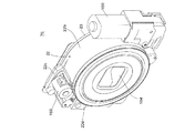
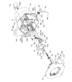
図1から図5を参照して、本発明を適用したズームレンズ鏡筒70の概略構造を説明する。このズームレンズ鏡筒70の撮像光学系は、物体(被写体)側から順に第1レンズ群LG1、第2レンズ群LG2、絞り兼用のシャッタ羽根S、第3レンズ群LG3、ローパスフィルタ25及び撮像素子71を備えており、以下の説明中で光軸方向とは、この撮影光学系の光軸Oと平行な方向を意味する。   A schematic structure of a zoom lens barrel 70 to which the present invention is applied will be described with reference to FIGS. The imaging optical system of the zoom lens barrel 70 includes, in order from the object (subject) side, a first lens group LG1, a second lens group LG2, a shutter blade S that also serves as an aperture, a third lens group LG3, a low-pass filter 25, and an imaging element. In the following description, the optical axis direction means a direction parallel to the optical axis O of the photographing optical system.

ローパスフィルタ25と撮像素子71はユニット化されて撮像素子ホルダ23に固定され、撮像素子ホルダ23がハウジング22の後部に固定される。ハウジング22の外側には、ズームモータ150とAFモータ160が支持されている。   The low-pass filter 25 and the image sensor 71 are unitized and fixed to the image sensor holder 23, and the image sensor holder 23 is fixed to the rear portion of the housing 22. A zoom motor 150 and an AF motor 160 are supported outside the housing 22.

第3レンズ群LG3を保持する3群レンズ枠51は、ハウジング22に対して光軸方向に移動可能に支持されていて、AFモータ160によって駆動される。   The third group lens frame 51 that holds the third lens group LG3 is supported so as to be movable in the optical axis direction with respect to the housing 22, and is driven by the AF motor 160.

ハウジング22の内側にはカム環(回転部材)11が支持されている。カム環11は、ズームモータ150の駆動力によって回転され、鏡筒収納状態(図4)から撮影状態(図5)になるまでの間は、回転しながら光軸方向に移動し、撮影状態におけるズーム域(図5上半のワイド端と図5下半のテレ端の間)では、光軸方向には定位置で回転される。より詳しくは、図12に示すように、カム環11は、光軸方向の後端部にギヤリング部11aが設けられ、ギヤリング部11a上にガイド突起11bが突設されている。ギヤリング部11aは、ズームモータ150によって回転されるズームギヤ28(図6、図7)に噛合しており、ガイド突起11bは、ハウジング22の内周面に形成したカム環ガイド溝(回転部材案内機構)22aに対して摺動可能に係合している。カム環ガイド溝22aは、光軸方向後方の螺旋溝部分22a-1と、光軸方向前方の撮影光軸Oを中心とする環状溝部分22a-2とを有し、鏡筒収納状態と撮影状態(ワイド端)の間では、ガイド突起11bがカム環ガイド溝22aの螺旋溝部分22a-1に案内されて、カム環11はハウジング22に対して回転しながら光軸方向に移動する。具体的には、カム環11は、鏡筒収納状態から撮影状態になるときに、回転しながら光軸方向前方(物体側)へ進出し、撮影状態から鏡筒収納状態になるときには逆に、回転しながら光軸方向後方へ後退する。また、ワイド端からテレ端までのズーム域では、ガイド突起11bがカム環ガイド溝22aの環状溝部分22a-2に案内されて、カム環11はハウジング22に対する光軸方向位置を変化させず、光軸方向の定位置で回転される。   A cam ring (rotating member) 11 is supported inside the housing 22. The cam ring 11 is rotated by the driving force of the zoom motor 150 and moves in the optical axis direction while rotating from the lens barrel storage state (FIG. 4) to the photographing state (FIG. 5). In the zoom range (between the wide end in the upper half of FIG. 5 and the tele end in the lower half of FIG. 5), it is rotated at a fixed position in the optical axis direction. More specifically, as shown in FIG. 12, the cam ring 11 is provided with a gearing portion 11a at the rear end portion in the optical axis direction, and a guide projection 11b is projected on the gearing portion 11a. The gearing portion 11 a meshes with the zoom gear 28 (FIGS. 6 and 7) rotated by the zoom motor 150, and the guide protrusion 11 b is a cam ring guide groove (rotating member guide mechanism) formed on the inner peripheral surface of the housing 22. ) Is slidably engaged with 22a. The cam ring guide groove 22a has a spiral groove portion 22a-1 at the rear in the optical axis direction and an annular groove portion 22a-2 with the photographing optical axis O at the front in the optical axis direction as the center. During the state (wide end), the guide protrusion 11b is guided by the spiral groove portion 22a-1 of the cam ring guide groove 22a, and the cam ring 11 moves in the optical axis direction while rotating with respect to the housing 22. Specifically, the cam ring 11 advances forward in the optical axis direction (object side) while rotating when the lens barrel storage state is changed to the photographing state, and conversely when the lens barrel storage state is changed from the photographing state, While rotating, it moves backward in the optical axis direction. In the zoom range from the wide end to the tele end, the guide protrusion 11b is guided by the annular groove portion 22a-2 of the cam ring guide groove 22a, and the cam ring 11 does not change the position in the optical axis direction with respect to the housing 22, It is rotated at a fixed position in the optical axis direction.

カム環11を挟んで第1繰出筒13と直進案内環10が支持されている。第1繰出筒13と直進案内環10はそれぞれハウジング22に対して光軸方向に直進案内されており、かつカム環11に対しては、相対回転は可能で光軸方向に共に移動するように結合されている。   The first feed cylinder 13 and the straight guide ring 10 are supported with the cam ring 11 in between. The first feeding cylinder 13 and the rectilinear guide ring 10 are each guided in a straight line with respect to the housing 22 in the optical axis direction, and can be relatively rotated with respect to the cam ring 11 and move together in the optical axis direction. Are combined.

直進案内環10は、2群レンズ移動枠8を光軸方向へ相対移動可能に直進案内している。2群レンズ移動枠8の内部には2群レンズ保持枠2を介して第2レンズ群LG2が保持され、第2レンズ群LG2の後部に、シャッタ羽根Sを保持するシャッタブロック100が支持されている。また、ハウジング22に対して光軸方向に直進案内された第1繰出筒13はさらに、第2繰出筒12を光軸方向へ相対移動可能に直進案内している。第2繰出筒12の内部には、1群レンズ保持枠1を介して第1レンズ群LG1が支持されている。   The rectilinear guide ring 10 guides the second group lens moving frame 8 so that it can move relative to the optical axis. The second lens group LG2 is held inside the second group lens moving frame 8 via the second group lens holding frame 2, and the shutter block 100 holding the shutter blades S is supported at the rear of the second lens group LG2. Yes. Further, the first feeding cylinder 13 guided linearly in the optical axis direction with respect to the housing 22 further guides the second feeding cylinder 12 so as to be relatively movable in the optical axis direction. A first lens group LG <b> 1 is supported inside the second feeding cylinder 12 via a first group lens holding frame 1.

第2繰出筒12は内径方向に突出する1群用カムフォロアCF1を有し、この1群用カムフォロアCF1が、カム環11の外周面に形成した1群制御カム溝CG1に摺動可能に嵌合している。第2繰出筒12は第1繰出筒13を介して光軸方向に直進案内されているため、カム環11が回転すると、1群制御カム溝CG1の形状に従って、第2繰出筒12すなわち第1レンズ群LG1が光軸方向へ所定の軌跡で移動する。   The second feeding cylinder 12 has a first group cam follower CF1 protruding in the inner diameter direction, and the first group cam follower CF1 is slidably fitted in a first group control cam groove CG1 formed on the outer peripheral surface of the cam ring 11. is doing. Since the second feeding cylinder 12 is guided linearly in the direction of the optical axis via the first feeding cylinder 13, when the cam ring 11 rotates, the second feeding cylinder 12, i.e., the first feeding cylinder 12, according to the shape of the first group control cam groove CG1. The lens group LG1 moves along a predetermined locus in the optical axis direction.

カム環11の内周面に形成した2群制御カム溝CG2に対し、2群レンズ移動枠8の外周面に設けた2群用カムフォロアCF2が係合している。2群レンズ移動枠8は直進案内環10を介して光軸方向に直進案内されているため、カム環11が回転すると、2群制御カム溝CG2の形状に従って、2群レンズ移動枠8すなわち第2レンズ群LG2が光軸方向へ所定の軌跡で移動する。   The second group cam follower CF2 provided on the outer peripheral surface of the second group lens moving frame 8 is engaged with the second group control cam groove CG2 formed on the inner peripheral surface of the cam ring 11. Since the second group lens moving frame 8 is linearly guided in the optical axis direction via the straight guide ring 10, when the cam ring 11 rotates, the second group lens moving frame 8, i.e., the first group moving frame 8 according to the shape of the second group control cam groove CG2. The two lens group LG2 moves along a predetermined locus in the optical axis direction.

2群レンズ移動枠8と第2繰出筒12の間には、圧縮ばねからなる群間付勢ばね27が挿入されており、2群レンズ移動枠8と第2繰出筒12は互いに離間する方向に付勢されている。   A group biasing spring 27 made of a compression spring is inserted between the second group lens moving frame 8 and the second feeding cylinder 12, and the second group lens moving frame 8 and the second feeding cylinder 12 are separated from each other. Is being energized.

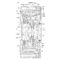
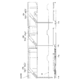
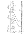
以上の構造からなるズームレンズ鏡筒70は次のように動作する。図1、図2及び図4に示す鏡筒収納状態では、図3及び図5に示す撮影状態よりも光軸方向の光学系の長さ(第1レンズ群LG1の物体側の面から撮像素子71の撮像面までの距離)が短くなっている。この鏡筒収納状態において撮影状態への移行信号(例えば、ズームレンズ鏡筒70が搭載されるカメラに設けたメインスイッチのオン)が入力されると、ズームモータ150が鏡筒繰出方向に駆動され、カム環11が回転しながら光軸方向前方へ繰り出される。直進案内環10と第1繰出筒13は、カム環11と共に前方に直進移動する。カム環11が回転すると、その内側では、直進案内環10を介して直進案内された2群レンズ移動枠8が、2群用カムフォロアCF2と2群制御カム溝CG2の関係によって光軸方向に所定の軌跡で移動される。また、カム環11が回転すると、該カム環11の外側では、第1繰出筒13を介して直進案内された第2繰出筒12が、1群用カムフォロアCF1と1群制御カム溝CG1の関係によって光軸方向に所定の軌跡で移動される。   The zoom lens barrel 70 having the above structure operates as follows. 1, 2, and 4, the length of the optical system in the direction of the optical axis (from the object-side surface of the first lens group LG <b> 1 to the imaging element) is greater than that in the imaging state illustrated in FIGS. 3 and 5. 71) (distance to the imaging surface) is shortened. When a transition signal to the photographing state in this lens barrel storage state (for example, a main switch provided in a camera on which the zoom lens barrel 70 is mounted) is input, the zoom motor 150 is driven in the lens barrel feeding direction. The cam ring 11 is fed forward in the optical axis direction while rotating. The rectilinear guide ring 10 and the first feed cylinder 13 move forward together with the cam ring 11. When the cam ring 11 rotates, on the inner side, the second group lens moving frame 8 guided linearly through the straight guide ring 10 is predetermined in the optical axis direction due to the relationship between the second group cam follower CF2 and the second group control cam groove CG2. It is moved by the trajectory. Further, when the cam ring 11 rotates, the second feeding cylinder 12 guided linearly through the first feeding cylinder 13 on the outside of the cam ring 11 is related to the first group cam follower CF1 and the first group control cam groove CG1. Is moved along a predetermined locus in the optical axis direction.

すなわち、鏡筒収納状態からの第1レンズ群LG1と第2レンズ群LG2の繰出量はそれぞれ、前者が、ハウジング22に対するカム環11の前方移動量と、該カム環11に対する第2繰出筒12のカム繰出量との合算値として決まり、後者が、ハウジング22に対するカム環11の前方移動量と、該カム環11に対する2群レンズ移動枠8のカム繰出量との合算値として決まる。ズーミングは、この第1レンズ群LG1と第2レンズ群LG2が互いの空気間隔を変化させながら撮影光軸Oに沿って移動することにより行われる。収納状態から鏡筒繰出を行うと、まず図5の上半断面に示すワイド端の繰出状態になり、さらにズームモータ150を鏡筒繰出方向に駆動させると、図5の下半断面に示すテレ端の繰出状態となる。テレ端とワイド端の間のズーム領域では、カム環11は前述の定位置回転を行い、光軸方向へは進退しない。収納状態への移行信号(例えば、カメラのメインスイッチのオフ)が入力されると、ズームモータ150が鏡筒収納方向に駆動され、ズームレンズ鏡筒70は以上の繰出動作とは逆の収納動作を行う。   That is, the first lens group LG1 and the second lens group LG2 are fed out from the lens barrel retracted state by the former moving amount of the cam ring 11 with respect to the housing 22 and the second feeding cylinder 12 with respect to the cam ring 11, respectively. The latter is determined as the sum of the amount of forward movement of the cam ring 11 relative to the housing 22 and the amount of cam extension of the second group lens moving frame 8 relative to the cam ring 11. Zooming is performed by moving the first lens group LG1 and the second lens group LG2 along the photographing optical axis O while changing the air interval between them. When the lens barrel is extended from the retracted state, first, the wide end extended state shown in the upper half section of FIG. 5 is obtained. When the zoom motor 150 is further driven in the lens barrel extending direction, the telephoto section shown in the lower half section of FIG. The end is extended. In the zoom region between the tele end and the wide end, the cam ring 11 rotates at the above-mentioned fixed position and does not advance or retreat in the optical axis direction. When a storage state transition signal (for example, turning off the main switch of the camera) is input, the zoom motor 150 is driven in the lens barrel storage direction, and the zoom lens barrel 70 is retracted in the opposite manner to the above-described extension operation. I do.

また、第2繰出筒12の前端部には、第1レンズ群LG1の前方を開閉可能なバリヤ羽根104が設けられており、鏡筒収納状態ではバリヤ羽根104が閉じており、撮影状態への繰り出し動作に応じてバリヤ羽根104が開かれる。   Further, a barrier blade 104 capable of opening and closing the front of the first lens group LG1 is provided at the front end portion of the second feeding cylinder 12, and the barrier blade 104 is closed when the lens barrel is housed, so that the shooting state is restored. The barrier blade 104 is opened according to the feeding operation.

第3レンズ群LG3を支持する3群レンズ枠51は、以上のズームモータ150による第1レンズ群LG1及び第2レンズ群LG2の駆動とは独立して、AFモータ160によって光軸方向に前後移動させることができる。そして、光学系がワイド端からテレ端までのズーム域にあるとき、測距手段によって得られた被写体距離情報に応じてAFモータ160を駆動することにより、第3レンズ群LG3が光軸方向に移動してフォーカシングが実行される。   The third lens group frame 51 that supports the third lens group LG3 is moved back and forth in the optical axis direction by the AF motor 160 independently of the driving of the first lens group LG1 and the second lens group LG2 by the zoom motor 150 described above. Can be made. When the optical system is in the zoom range from the wide end to the tele end, the third lens group LG3 is moved in the optical axis direction by driving the AF motor 160 according to the subject distance information obtained by the distance measuring means. Move to perform focusing.

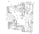
続いて、3群レンズ枠(光学要素保持部材)51の位置制御機構を説明する。ハウジング22は、カム環ガイド溝22aを内周面に有する、撮影光軸Oを中心とする円筒状部(固定筒部材)22bと、円筒状部22bの後端部外側に位置するAF機構組付部22cと、AF機構組付部22cの前方に位置する前方壁部22dとを有している。図6に示すように、AFモータ160の回転出力軸に設けたピニオン160aが、ハウジング22のAF機構組付部22cの後面側に突出する。AF機構組付部22cの後面側には、ピニオン160aに噛合する中間ギヤ57と、該中間ギヤ57に噛合する従動ギヤ56が軸支されていて、ピニオン160aの回転は、このギヤ列を介して、従動ギヤ56と一体に回転するスクリューシャフト58に伝達される。スクリューシャフト58は、ハウジング22と撮像素子ホルダ23の間に、撮影光軸Oと略平行な回転軸を中心として回転可能に支持されている。スクリューシャフト58の外周面に形成した送りねじは、光軸方向に直進案内されたAFナット54に螺合しており、スクリューシャフト58を正逆に回転させることにより、AFナット54が光軸方向に進退移動される。   Next, the position control mechanism of the third group lens frame (optical element holding member) 51 will be described. The housing 22 has a cam ring guide groove 22a on the inner peripheral surface, a cylindrical portion (fixed cylinder member) 22b centered on the photographing optical axis O, and an AF mechanism group positioned outside the rear end portion of the cylindrical portion 22b. Attached portion 22c and a front wall portion 22d positioned in front of the AF mechanism assembling portion 22c are provided. As shown in FIG. 6, the pinion 160 a provided on the rotation output shaft of the AF motor 160 protrudes to the rear surface side of the AF mechanism assembly portion 22 c of the housing 22. An intermediate gear 57 meshing with the pinion 160a and a driven gear 56 meshing with the intermediate gear 57 are pivotally supported on the rear surface side of the AF mechanism assembling portion 22c, and the rotation of the pinion 160a is via this gear train. Thus, it is transmitted to a screw shaft 58 that rotates integrally with the driven gear 56. The screw shaft 58 is supported between the housing 22 and the image sensor holder 23 so as to be rotatable about a rotation axis substantially parallel to the photographing optical axis O. A feed screw formed on the outer peripheral surface of the screw shaft 58 is screwed into an AF nut 54 that is guided in a straight line in the optical axis direction. By rotating the screw shaft 58 in the forward and reverse directions, the AF nut 54 is moved in the optical axis direction. Moved forward and backward.

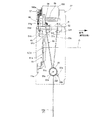
図7ないし図9に示すように、3群レンズ枠51は、第3レンズ群LG3を保持するレンズ保持部51aから、撮影光軸Oを挟んで略対称の径方向に一対のガイド腕部51b、51cを延設させている。ハウジング22と撮像素子ホルダ23の間に撮影光軸Oと平行な3群ガイド軸52が設けられ、この3群ガイド軸52に対して、3群レンズ枠51の一方のガイド腕部51bの先端部付近に形成したガイド穴51dが摺動自在に挿通支持されている。3群レンズ枠51は、他方のガイド腕部51cの先端部に設けた回転規制キー51eを、ハウジング22内周面の回転規制溝22eに係合させて回転規制されており、3群ガイド軸52に沿う光軸方向の直進移動のみ可能に案内されている。   As shown in FIGS. 7 to 9, the third group lens frame 51 includes a pair of guide arm portions 51b in a substantially symmetric radial direction across the photographing optical axis O from a lens holding portion 51a that holds the third lens group LG3. , 51c are extended. A third group guide shaft 52 parallel to the photographing optical axis O is provided between the housing 22 and the image sensor holder 23, and the tip of one guide arm portion 51 b of the third group lens frame 51 with respect to the third group guide shaft 52. A guide hole 51d formed in the vicinity of the portion is slidably inserted and supported. The third group lens frame 51 is restricted in rotation by engaging a rotation restricting key 51e provided at the tip of the other guide arm 51c with the rotation restricting groove 22e on the inner peripheral surface of the housing 22. It is guided so that only a straight movement in the optical axis direction along the line 52 is possible.

3群レンズ枠51は、トーションばね(付勢手段)55によって光軸方向前方に付勢されている。図7、図9及び図10に示すように、トーションばね55は、コイル部(揺動中心部)55aと、該コイル部55aから外径方向に突出する支持アーム55bと付勢アーム(着力部)55cを有しており、コイル部55aが、ハウジング22に設けたばね支持突起22fに支持される。ばね支持突起22fは、ハウジング22の円筒状部22bの外側に、撮影光軸Oと平行な(撮影光軸Oを含む)上下方向平面P(図11)に対して略直交する方向へ軸線を向けて形成された円筒状の突起である。ばね支持突起22fの中心に形成されたねじ穴に対してばね留めねじ39を固定することによって、ばね支持突起22fの円筒状外面に対してトーションばね55のコイル部55aが抜け止めされた状態で保持される。この保持状態のコイル部55aの軸線は、ばね支持突起22fの軸線と概ね一致する。   The third group lens frame 51 is biased forward in the optical axis direction by a torsion spring (biasing means) 55. As shown in FIGS. 7, 9 and 10, the torsion spring 55 includes a coil part (swinging center part) 55a, a support arm 55b protruding from the coil part 55a in the outer diameter direction, and an urging arm (energizing part). ) 55c, and the coil portion 55a is supported by a spring support protrusion 22f provided on the housing 22. The spring support protrusion 22f has an axial line on the outside of the cylindrical portion 22b of the housing 22 in a direction substantially orthogonal to the vertical plane P (FIG. 11) parallel to the imaging optical axis O (including the imaging optical axis O). It is the cylindrical protrusion formed toward. By fixing the spring retaining screw 39 to the screw hole formed at the center of the spring support protrusion 22f, the coil portion 55a of the torsion spring 55 is prevented from coming off from the cylindrical outer surface of the spring support protrusion 22f. Retained. The axis of the coil portion 55a in the holding state substantially coincides with the axis of the spring support protrusion 22f.

ハウジング22の円筒状部22bの外面には、ばね支持突起22fの近傍に位置させてばね掛け突起22g(図10)が設けられ、トーションばね55の支持アーム55bは、このばね掛け突起22gに掛けられている。一方、付勢アーム55cは、3群レンズ枠51のガイド穴51dの近傍に設けたばね掛け突起51fに掛けられている。付勢アーム55cは、コイル部55aの軸線に略一致する(すなわち撮影光軸Oと平行な上下方向平面Pに対して略直交する)揺動中心軸55xを中心(支点)として揺動することが可能な揺動着力部であって、ばね掛け突起51fに掛けられていない自由状態では図10に「55c(F)」で示す方向を向いている。そして、この自由状態から付勢アーム55cを図10中の反時計方向に約半回転させて、該付勢アーム55cの先端部付近をばね掛け突起51fの光軸方向後方の面に当て付けることにより、トーションばね55の撓み(ねじれ)量が大きくなり、その撓み解消方向の力は、付勢アーム55cがばね掛け突起51fを光軸方向前方へ押圧する荷重として作用する。すなわち、付勢アーム55cを介して3群レンズ枠51に対して光軸方向前方への付勢力が与えられる着力状態となる。   A spring hooking protrusion 22g (FIG. 10) is provided on the outer surface of the cylindrical portion 22b of the housing 22 in the vicinity of the spring support protrusion 22f. The support arm 55b of the torsion spring 55 is hooked on the spring hooking protrusion 22g. It has been. On the other hand, the urging arm 55 c is hooked on a spring hooking protrusion 51 f provided in the vicinity of the guide hole 51 d of the third group lens frame 51. The urging arm 55c swings about a swing center axis 55x that is substantially coincident with the axis of the coil portion 55a (that is, substantially perpendicular to the vertical plane P parallel to the photographing optical axis O) as a center (fulcrum). In a free state in which the swinging force applying portion is not hung on the spring hooking protrusion 51f, the swinging force portion faces the direction indicated by "55c (F)" in FIG. Then, from this free state, the urging arm 55c is rotated approximately half counterclockwise in FIG. 10, and the vicinity of the tip of the urging arm 55c is applied to the rear surface in the optical axis direction of the spring hooking projection 51f. As a result, the amount of bending (twisting) of the torsion spring 55 increases, and the force in the direction of bending cancellation acts as a load for the urging arm 55c to press the spring hooking protrusion 51f forward in the optical axis direction. That is, it is in an applied force state in which an urging force forward in the optical axis direction is applied to the third group lens frame 51 via the urging arm 55c.

このようにしてトーションばね55により光軸方向前方への付勢力を与えられた3群レンズ枠51は、ガイド穴51dの近傍に設けた(すなわちガイド腕部51bの先端部付近に位置する)ナット当付部51gがAFナット54に当て付くことによって、前方への移動が規制される。すなわち、3群レンズ枠51は、トーションばね55の付勢力によってナット当付部51gをAFナット54に当接させた状態で保持され、3群レンズ枠51の光軸方向の前後位置はAFナット54に依存して決まる。前述の通り、AFナット54は、AFモータ160のピニオン160aを正逆に回転駆動することにより、スクリューシャフト58によって光軸方向へ進退移動されるため、結果として、3群レンズ枠51の光軸方向位置は、AFモータ160の駆動方向と駆動量に応じて制御される。例えば、AFモータ160によって前方にAFナット54を移動させると、AFナット54の移動分だけ、トーションばね55の付勢力によって3群レンズ枠51が追随して前方に移動する。逆に、前方の移動位置からAFナット54を後方に移動させると、該AFナット54がナット当付部51gを押し込み、3群レンズ枠51はトーションばね55の付勢力に抗して後方へ移動される。   The third group lens frame 51 thus provided with a biasing force forward in the optical axis direction by the torsion spring 55 is a nut provided in the vicinity of the guide hole 51d (that is, positioned in the vicinity of the distal end portion of the guide arm portion 51b). When the contact portion 51g contacts the AF nut 54, the forward movement is restricted. That is, the third group lens frame 51 is held in a state where the nut abutting portion 51g is in contact with the AF nut 54 by the urging force of the torsion spring 55, and the front and rear positions of the third group lens frame 51 in the optical axis direction are the AF nuts. Depends on 54. As described above, the AF nut 54 is moved forward and backward in the optical axis direction by the screw shaft 58 by rotating the pinion 160a of the AF motor 160 forward and backward, and as a result, the optical axis of the third group lens frame 51 is moved. The direction position is controlled according to the driving direction and driving amount of the AF motor 160. For example, when the AF nut 54 is moved forward by the AF motor 160, the third group lens frame 51 is moved forward by the urging force of the torsion spring 55 by the amount of movement of the AF nut 54. On the contrary, when the AF nut 54 is moved backward from the forward movement position, the AF nut 54 pushes the nut abutting portion 51g, and the third lens group frame 51 moves backward against the urging force of the torsion spring 55. Is done.

ハウジング22には、AFモータ160による3群レンズ枠51の光軸方向の後方移動端を検出する原点位置検出センサ40が設けられている。原点位置検出センサ40は、透過型フォトインタラプタからなり、二股状の投光部と受光部の間に3群レンズ枠51のセンサ通過板51hが位置した状態が、該3群レンズ枠51の後方移動端であると検知される。AFモータ160はステッピングモータからなり、フォーカシングに際しての第3レンズ群LG3の移動量は、この後方移動端を原点位置としたAFモータ160の駆動ステップ数として演算される。図10に実線で示しているのが、AFモータ160に制御される可動範囲における3群レンズ枠51の後方移動端であり、同図に二点鎖線で示しているのが、同可動範囲における3群レンズ枠51の前方移動端である。   The housing 22 is provided with an origin position detection sensor 40 that detects the rearward movement end of the third group lens frame 51 in the optical axis direction by the AF motor 160. The origin position detection sensor 40 is formed of a transmissive photo interrupter, and the state where the sensor passage plate 51h of the third group lens frame 51 is positioned between the bifurcated light projecting unit and the light receiving unit is located behind the third group lens frame 51. Detected as moving end. The AF motor 160 is a stepping motor, and the amount of movement of the third lens group LG3 during focusing is calculated as the number of driving steps of the AF motor 160 with the rearward movement end as the origin position. A solid line in FIG. 10 shows the rear moving end of the third group lens frame 51 in the movable range controlled by the AF motor 160, and a two-dot chain line in FIG. 10 shows in the movable range. This is the front moving end of the third group lens frame 51.

以上のトーションばね55による付勢構造によると、3群レンズ枠51がAFモータ160による前後の移動端の間で移動されるときの付勢アーム55cの揺動角(トーションばね55の撓み量)は、自由状態からばね掛け突起51fに係合させる着力状態にさせるときの付勢アーム55cの揺動角(トーションばね55の撓み量)に比べて遙かに小さい。そのため、AFモータ160による3群レンズ枠51の可動範囲におけるトーションばね55の荷重の変動が小さく、3群レンズ枠51の駆動に必要とされるエネルギーが低いレベルで平均化され、AFモータ160の負担を軽減することができる。また、3群レンズ枠51の移動に応じた荷重変動が小さいので、移動範囲の全域に亘ってスムーズに駆動させることができ、AFモータ160からの駆動力を伝達するギヤ列からの異音も発生しにくくなっている。   According to the biasing structure by the torsion spring 55 described above, the swing angle of the biasing arm 55c when the third lens group frame 51 is moved between the front and rear moving ends by the AF motor 160 (the amount of deflection of the torsion spring 55). Is much smaller than the swing angle (the amount of deflection of the torsion spring 55) of the urging arm 55c when the biasing arm 55c is brought into an applied state in which it is engaged from the free state. Therefore, the fluctuation of the load of the torsion spring 55 in the movable range of the third group lens frame 51 by the AF motor 160 is small, and the energy required for driving the third group lens frame 51 is averaged at a low level. The burden can be reduced. Further, since the load fluctuation according to the movement of the third group lens frame 51 is small, it can be driven smoothly over the entire movement range, and abnormal noise from the gear train that transmits the driving force from the AF motor 160 is also generated. It is hard to occur.

トーションばね55において荷重変動が小さく抑えられている要因として、揺動の支点であるコイル部55aから、3群レンズ枠51への着力点(作用点)であるばね掛け突起51fまでの付勢アーム55cの長さも関係している。揺動中心軸55xからばね掛け突起51fに対する着力点までの距離、すなわち付勢アーム55cの先端付近の揺動の回転半径が大きくなるほど、3群レンズ枠51の単位移動量あたりの付勢アーム55cの変位角は小さくなり、ばね荷重の変動を抑制できる。そして、トーションばね55をハウジング22の円筒状部22bの外側に位置させることで、円筒状部22b内にある他の部材と干渉することなく、付勢アーム55cにこのような長さを持たせることが可能になっている。   As a factor that suppresses the load fluctuation in the torsion spring 55, the urging arm from the coil portion 55a that is the fulcrum of swing to the spring hooking projection 51f that is the point of application (action point) to the third group lens frame 51 The length of 55c is also relevant. The biasing arm 55c per unit movement amount of the third group lens frame 51 becomes larger as the distance from the swinging central axis 55x to the force applied point to the spring hooking protrusion 51f, that is, the rotation radius of swinging near the tip of the biasing arm 55c increases. The displacement angle becomes smaller, and the fluctuation of the spring load can be suppressed. Then, by positioning the torsion spring 55 outside the cylindrical portion 22b of the housing 22, the biasing arm 55c has such a length without interfering with other members in the cylindrical portion 22b. It is possible.

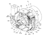
トーションばね55をハウジング22の円筒状部22bの外側に位置させることで以上の効果が得られるが、その反面、図6に示すように、トーションばね55がハウジング22による保護を受けない状態になる。図12に示すように、ハウジング22の円筒状部22bは、内周面に設けた3つのカム環ガイド溝22aが、その周方向の略全域に亘って形成されている関係上、周方向の途中に途絶部分のない完全な円筒体である必要がある。ハウジング22は合成樹脂の成形品として形成されるが、完全円筒体である円筒状部22bの外側にさらにトーションばね55を覆う壁部を有するような二重壁構造にすることは製造上難しい。   Although the above effect can be obtained by positioning the torsion spring 55 outside the cylindrical portion 22b of the housing 22, the torsion spring 55 is not protected by the housing 22 as shown in FIG. . As shown in FIG. 12, the cylindrical portion 22b of the housing 22 has three cam ring guide grooves 22a provided on the inner peripheral surface thereof, and is formed in the circumferential direction because it is formed over substantially the entire area in the circumferential direction. It must be a complete cylinder with no interruptions along the way. Although the housing 22 is formed as a molded product of synthetic resin, it is difficult to manufacture a double wall structure having a wall portion that covers the torsion spring 55 outside the cylindrical portion 22b that is a complete cylindrical body.

本実施形態のズームレンズ鏡筒70では、ハウジング22の後部に取り付けられる撮像素子ホルダ23に、トーションばね55の外側を覆う保護壁部(保護壁部材)23aが設けられている。図2、図7、図8及び図11に示すように、保護壁部23aは、トーションばね55の付勢アーム55cの揺動平面と略平行な平面状の側壁部(平面部)23bと、その下方のコイル部55aを囲む箱状部23cを有していて、側壁部23bから箱状部23cに亘る光軸方向の前縁部が、ハウジング22の前方壁部22dに当接し、箱状部23cの側縁部が、ハウジング22に設けた下方支持部22hに当接される。前方壁部22dと下方支持部22hにはそれぞれ、保護壁部23a側の当接縁部を嵌合支持する段部22d-1、22h-1が形成されている。図8に示すように、保護壁部23aの側壁部23bの内側面には、3群レンズ枠51の移動時にばね掛け突起51fとの干渉を防ぐ光軸方向溝23dが形成され、光軸方向溝23dの後部には原点位置検出センサ40を収納するセンサ収納部23eが形成されている。   In the zoom lens barrel 70 of the present embodiment, the image sensor holder 23 attached to the rear portion of the housing 22 is provided with a protective wall portion (protective wall member) 23 a that covers the outside of the torsion spring 55. As shown in FIGS. 2, 7, 8, and 11, the protective wall portion 23 a includes a planar side wall portion (planar portion) 23 b that is substantially parallel to the swinging plane of the urging arm 55 c of the torsion spring 55, A box-like portion 23c surrounding the lower coil portion 55a is provided, and a front edge portion in the optical axis direction extending from the side wall portion 23b to the box-like portion 23c abuts on the front wall portion 22d of the housing 22 to form a box-like shape. A side edge portion of the portion 23 c comes into contact with a lower support portion 22 h provided in the housing 22. Step portions 22d-1 and 22h-1 for fitting and supporting the contact edge on the protective wall portion 23a side are formed on the front wall portion 22d and the lower support portion 22h, respectively. As shown in FIG. 8, an optical axis direction groove 23d is formed on the inner side surface of the side wall portion 23b of the protective wall portion 23a to prevent interference with the spring hooking projection 51f when the third group lens frame 51 is moved. A sensor storage portion 23e for storing the origin position detection sensor 40 is formed at the rear portion of the groove 23d.

撮像素子ホルダ23をハウジング22に組み付けるときには、保護壁部23aにおける箱状部23cの側縁部を下方支持部22hの段部22h-1上に支持させつつ前方へスライドさせていき、撮像素子ホルダ23の本体部がハウジング22の後面部に当接すると、保護壁部23aの前縁部も前方壁部22dに当て付き段部22d-1に嵌合する。そして、ハウジング22に対して撮像素子ホルダ23をねじ留め固定することによって、図2に示すように保護壁部23aがトーションばね55の外側を完全に塞いだ保護状態になる。この保護状態では、図11に示すように、ハウジング22の円筒状部22bの外周面と、撮像素子ホルダ23の保護壁部23aとの間の収納空間Q内にトーションばね55が保持されており、トーションばね55は、ズームレンズ鏡筒70内部の可動部材に対しては円筒状部22bによって接触から保護され、ズームレンズ鏡筒70の外側からの接触も保護壁部23aによって保護される。したがって、トーションばね55、特に付勢アーム55cが、別の部材などとの接触によって、通常使用状態での弾性変形とは異なる不可逆的な変形をしてしまうおそれがなく、ズームレンズ鏡筒70が組まれた状態では、3群レンズ枠51の位置制御の精度が損なわれない。   When the image sensor holder 23 is assembled to the housing 22, the side edge of the box-shaped portion 23c in the protective wall 23a is slid forward while being supported on the step portion 22h-1 of the lower support portion 22h. When the main body portion 23 abuts on the rear surface portion of the housing 22, the front edge portion of the protective wall portion 23a is also brought into contact with the front wall portion 22d and fitted into the stepped portion 22d-1. Then, by screwing and fixing the image pickup device holder 23 to the housing 22, the protection wall 23 a is in a protected state in which the outside of the torsion spring 55 is completely closed as shown in FIG. 2. In this protected state, as shown in FIG. 11, the torsion spring 55 is held in the storage space Q between the outer peripheral surface of the cylindrical portion 22 b of the housing 22 and the protective wall portion 23 a of the image sensor holder 23. The torsion spring 55 is protected from contact with the movable member inside the zoom lens barrel 70 by the cylindrical portion 22b, and contact from the outside of the zoom lens barrel 70 is also protected by the protective wall portion 23a. Therefore, there is no possibility that the torsion spring 55, particularly the urging arm 55c, may be irreversibly deformed different from the elastic deformation in the normal use state due to contact with another member or the like, and the zoom lens barrel 70 In the assembled state, the accuracy of position control of the third group lens frame 51 is not impaired.

このように、ハウジング22に対して固定される撮像素子ホルダ23に、ハウジング22への取り付け状態でトーションばね55の外側を覆う保護壁部23aを設けたので、ハウジング22の外側に位置するトーションばね55を保護することができる。特に、本実施形態のように、ハウジング22において円筒状部22bが完全な円筒状をなし、この円筒状部22bの外側にトーションばね55を覆うような壁部を形成することが樹脂成形では難しい構造においても、ハウジング22の形状に依存することなく、確実にトーションばね55を保護することができる。なお、ハウジング22のうち、保護壁部23aが当接される前方壁部22dと下方支持部22hはいずれも、円筒状部22bの外周面から突出する板状の部分であり、ばね支持突起22fと同じ方向の型抜きで形成可能であるため、保護壁部23aとは異なり、ハウジング22の一部として成形が可能である。   As described above, since the image sensor holder 23 fixed to the housing 22 is provided with the protective wall portion 23a that covers the outside of the torsion spring 55 in a state of being attached to the housing 22, the torsion spring positioned outside the housing 22 is provided. 55 can be protected. In particular, as in the present embodiment, in the resin molding, it is difficult to form a wall portion that covers the torsion spring 55 outside the cylindrical portion 22b in the housing 22 where the cylindrical portion 22b forms a complete cylindrical shape. Even in the structure, the torsion spring 55 can be reliably protected without depending on the shape of the housing 22. In the housing 22, the front wall portion 22d and the lower support portion 22h with which the protective wall portion 23a abuts are both plate-like portions protruding from the outer peripheral surface of the cylindrical portion 22b, and the spring support protrusion 22f. Unlike the protective wall portion 23a, it can be formed as a part of the housing 22 because it can be formed by punching in the same direction as the first embodiment.

以上の実施形態では、ハウジング22の円筒状部22bの内周面に形成したカム環ガイド溝22aの螺旋溝部分22a-1によってカム環11の光軸方向移動を行わせているが、これに代えて、図13のようなヘリコイドを用いた繰出構造を用いてもよい。図13に示すハウジング22′の円筒状部22b′は、螺旋溝部分22a-1′と環状溝部分22a-2′からなるカム環ガイド溝(回転部材案内機構)22a′を内周面に有しており、このカム環ガイド溝22a′に対してカム環11′のギヤリング部11a′に設けたガイド突起11b′が嵌まっている。先の実施形態とは異なり、カム環11′の光軸方向への繰出案内は、カム環ガイド溝22a′の螺旋溝部分22a-1′とガイド突起11b′の関係ではなく、円筒状部22b′の内周面に形成した内面ヘリコイド(回転部材案内機構)22zと、カム環11′のギヤリング部11a′上に形成した外面ヘリコイド(回転部材案内機構)11zによって行われる。そして、ヘリコイド11z、22zによってカム環11′が光軸方向前方まで繰り出されると、ヘリコイド螺合が外れると共に、ガイド突起11b′がカム環ガイド溝22a′の環状溝部分22a-2′に進入し、カム環11′は光軸方向に移動されない定位置回転状態となる。この実施形態においても、カム環11′の移動制御のために、ハウジング22′の円筒状部22b′は周方向の途絶部分のない完全な円筒体とされているため、先の実施形態と同様のばね保護構造が有効である。   In the above embodiment, the cam ring 11 is moved in the optical axis direction by the spiral groove portion 22a-1 of the cam ring guide groove 22a formed on the inner peripheral surface of the cylindrical portion 22b of the housing 22. Instead, a payout structure using a helicoid as shown in FIG. 13 may be used. The cylindrical portion 22b 'of the housing 22' shown in FIG. 13 has a cam ring guide groove (rotating member guide mechanism) 22a 'composed of a spiral groove portion 22a-1' and an annular groove portion 22a-2 'on the inner peripheral surface. The guide projection 11b 'provided on the gear ring portion 11a' of the cam ring 11 'is fitted into the cam ring guide groove 22a'. Unlike the previous embodiment, the guide of the cam ring 11 'in the optical axis direction is not the relationship between the spiral groove portion 22a-1' of the cam ring guide groove 22a 'and the guide protrusion 11b', but the cylindrical portion 22b. The inner surface helicoid (rotating member guide mechanism) 22z formed on the inner peripheral surface of ′ and the outer surface helicoid (rotating member guide mechanism) 11z formed on the gearing portion 11a ′ of the cam ring 11 ′. Then, when the cam ring 11 'is extended forward in the optical axis direction by the helicoids 11z and 22z, the helicoid screwing is released and the guide projection 11b' enters the annular groove portion 22a-2 'of the cam ring guide groove 22a'. The cam ring 11 ′ is in a fixed position rotation state that is not moved in the optical axis direction. Also in this embodiment, since the cylindrical portion 22b 'of the housing 22' is a complete cylindrical body without a discontinuous portion in the circumferential direction in order to control the movement of the cam ring 11 ', the same as in the previous embodiment. The spring protection structure is effective.

以上、図示実施形態に基づき本発明を説明したが、本発明は、この実施形態に限定されるものではない。例えば、実施形態においては、光軸方向に移動付勢される光学要素が、フォーカシングレンズ群として機能する第3レンズ群LG3であるが、本発明において付勢手段により移動付勢される光学要素は、このようなレンズ群以外のものであってもよい。   As mentioned above, although this invention was demonstrated based on illustration embodiment, this invention is not limited to this embodiment. For example, in the embodiment, the optical element that is moved and urged in the optical axis direction is the third lens group LG3 that functions as a focusing lens group, but in the present invention, the optical element that is moved and urged by the urging means is Other than such a lens group may be used.

また、実施形態の付勢手段はトーションばね55であるが、トーションばね55の付勢アーム55cに相当する着力部分を独立したレバー部材とし、このレバー部材に対して別のばね部材で付勢力を付与するタイプの付勢手段を備えたレンズ鏡筒にも、本発明は適用が可能である。   The urging means of the embodiment is the torsion spring 55, but the urging force portion corresponding to the urging arm 55c of the torsion spring 55 is an independent lever member, and the urging force is applied to this lever member by another spring member. The present invention can also be applied to a lens barrel provided with a biasing means of the type to be applied.

また、実施形態のトーションばね55は、光軸方向前方への付勢力を与えるものであるが、本発明では付勢手段による付勢の方向はこれに限定されず、光軸方向後方への付勢手段であってもよい。   The torsion spring 55 according to the embodiment gives a biasing force forward in the optical axis direction. However, in the present invention, the biasing direction by the biasing means is not limited to this, and the biasing force toward the rear in the optical axis direction is not limited thereto. It may be a force means.

また、実施形態では、トーションばね55のコイル部55aを支持するばね支持突起22fが、ハウジング22の円筒状部22b側に設けられているが、撮像素子ホルダ23の保護壁部23a側に同様の支持突起を設けることも可能である。   In the embodiment, the spring support protrusion 22 f that supports the coil portion 55 a of the torsion spring 55 is provided on the cylindrical portion 22 b side of the housing 22, but similar to the protective wall portion 23 a side of the image sensor holder 23. Support protrusions can also be provided.

本発明を適用したズームレンズ鏡筒の収納状態の外観斜視図である。It is an external appearance perspective view of the storage state of the zoom lens barrel to which the present invention is applied. 同ズームレンズ鏡筒の収納状態を後方から見た外観斜視図である。It is the external appearance perspective view which looked at the accommodation state of the zoom lens barrel from back. 同ズームレンズ鏡筒の撮影状態の外観斜視図である。It is an external appearance perspective view of the photographing state of the zoom lens barrel. 同ズームレンズ鏡筒の収納状態の断面図である。It is sectional drawing of the accommodation state of the zoom lens barrel. 同ズームレンズ鏡筒の撮影状態の断面図である。It is sectional drawing of the imaging state of the zoom lens barrel. 撮像素子ホルダを取り外した状態のズームレンズ鏡筒の後方斜視図である。It is a rear perspective view of the zoom lens barrel with the image sensor holder removed. 3群レンズ枠の位置制御機構を分解した状態の後方斜視図である。It is a back perspective view of the state where the position control mechanism of the 3 group lens frame was disassembled. 3群レンズ枠の位置制御機構を分解した状態の前方斜視図である。It is a front perspective view of the state which decomposed | disassembled the position control mechanism of a 3 group lens frame. 3群レンズ枠とその位置制御機構の要部を示す後方斜視図である。It is a back perspective view which shows the principal part of a 3 group lens frame and its position control mechanism. 3群レンズ枠を付勢するトーションばねの作用を示す側面図である。It is a side view which shows the effect | action of the torsion spring which urges | biases a 3 group lens frame. 3群レンズ枠を付勢するトーションばねの保護収納構造を示す、ズームレンズ鏡筒の要部の背面図である。It is a rear view of the principal part of a zoom lens barrel showing the protective housing structure of a torsion spring that biases the third group lens frame. ハウジングの円筒状部とカム環の展開平面図である。It is a development top view of the cylindrical part of a housing, and a cam ring. ハウジングの円筒状部とカム環の異なる実施形態を示す展開平面図である。It is an expansion | deployment top view which shows embodiment from which the cylindrical part of a housing differs from a cam ring.

符号の説明Explanation of symbols

1 1群レンズ保持枠
2 2群レンズ保持枠
8 2群レンズ移動枠
10 直進案内環
11 11′ カム環(回転部材)
11a 11a′ ギヤリング部
11b 11b′ ガイド突起
11z 外面ヘリコイド(回転部材案内機構)
12 第2繰出筒
13 第1繰出筒
22 22′ ハウジング
22a 22a′ カム環ガイド溝(回転部材案内機構)
22a-1 22a-1′ 螺旋溝部分
22a-2 22a-2′ 環状溝部分
22b 円筒状部(固定筒部材)
22c AF機構組付部
22d 前方壁部
22d-1 段部
22e 回転規制溝
22f ばね支持突起
22g ばね掛け突起
22h 下方支持部
22h-1 段部
22z 内面ヘリコイド(回転部材案内機構)
23 撮像素子ホルダ
23a 保護壁部(保護壁部材)
23b 側壁部(平面部)
23c 箱状部
23d 光軸方向溝
23e センサ収納部
25 ローパスフィルタ
27 群間付勢ばね
28 ズームギヤ
39 ばね留めねじ
40 原点位置検出センサ
51 3群レンズ枠(光学要素保持部材)
51a レンズ保持部
51b 51c ガイド腕部
51d ガイド穴
51e 回転規制キー
51f ばね掛け突起
51g ナット当付部
51h センサ通過板
52 3群ガイド軸
54 AFナット
55 トーションばね(付勢手段)
55a コイル部(揺動中心部)
55b 支持アーム
55c 付勢アーム(着力部)
55x 揺動中心軸
56 従動ギヤ
57 中間ギヤ
58 スクリューシャフト
70 ズームレンズ鏡筒
71 撮像素子
100 シャッタブロック
104 バリヤ羽根
150 ズームモータ
160 AFモータ
160a ピニオン
CF1 1群用カムフォロア
CF2 2群用カムフォロア
CG1 1群制御カム溝
CG2 2群制御カム溝
LG1 第1レンズ群
LG2 第2レンズ群
LG3 第3レンズ群
O 撮影光学系の光軸
P 撮影光軸と平行な上下方向平面
S シャッタ羽根
Q ハウジングの円筒状部と撮像素子ホルダの保護壁部の間の収納空間
DESCRIPTION OF SYMBOLS 1 1st group lens holding frame 2 2nd group lens holding frame 8 2nd group lens moving frame 10 Straight guide ring 11 11 'Cam ring (rotating member)
11a 11a 'gearing part 11b 11b' guide projection 11z outer surface helicoid (rotating member guide mechanism)
12 Second feeding cylinder 13 First feeding cylinder 22 22 'Housing 22a 22a' Cam ring guide groove (rotating member guide mechanism)
22a-1 22a-1 'Spiral groove part 22a-2 22a-2' Annular groove part 22b Cylindrical part (fixed cylinder member)
22c AF mechanism assembly part 22d Front wall part 22d-1 Step part 22e Rotation restricting groove 22f Spring support protrusion 22g Spring hooking protrusion 22h Lower support part 22h-1 Step part 22z Inner surface helicoid (rotating member guide mechanism)
23 Image sensor holder 23a Protective wall part (protective wall member)
23b Side wall (plane part)
23c Box-shaped portion 23d Optical axis direction groove 23e Sensor housing portion 25 Low pass filter 27 Group bias spring 28 Zoom gear 39 Spring retaining screw 40 Origin position detection sensor 51 Third group lens frame (optical element holding member)
51a Lens holding portion 51b 51c Guide arm portion 51d Guide hole 51e Rotation restriction key 51f Spring hooking projection 51g Nut abutting portion 51h Sensor passage plate 52 Third group guide shaft 54 AF nut 55 Torsion spring (biasing means)
55a Coil (swinging center)
55b Support arm 55c Energizing arm (forced portion)
55x Oscillation center shaft 56 Driven gear 57 Intermediate gear 58 Screw shaft 70 Zoom lens barrel 71 Image sensor 100 Shutter block 104 Barrier blade 150 Zoom motor 160 AF motor 160a Pinion CF1 First group cam follower CF2 Second group cam follower CG1 First group control Cam groove CG2 Second group control cam groove LG1 First lens group LG2 Second lens group LG3 Third lens group O Optical axis P of photographing optical system Vertical plane S parallel to photographing optical axis Shutter blades Q Cylindrical portion of housing Storage space between the protective walls of the image sensor holder

Claims (6)

撮影光学系を構成する光学要素を保持し光軸方向に移動可能な光学要素保持部材;
上記撮影光学系を囲む固定筒部材;
上記固定筒部材の外側に位置し、光軸と平行な平面に対して略直交する軸を中心として揺動可能で、揺動中心部から径方向に延びる着力部を介して上記光学要素保持部材を光軸方向に付勢する付勢手段;及び
上記固定筒部材とは別部材からなり、該固定筒部材に取り付けられて固定筒部材外面との間に上記付勢手段の収納空間を形成する保護壁部材;
を備えたことを特徴とするレンズ鏡筒。
An optical element holding member that holds an optical element constituting the photographing optical system and is movable in the optical axis direction;
A fixed cylinder member surrounding the imaging optical system;
The optical element holding member is located on the outer side of the fixed cylinder member and is swingable about an axis substantially orthogonal to a plane parallel to the optical axis, and via an attachment portion extending in the radial direction from the swing center portion. An urging means for urging the urging means in the direction of the optical axis; and a member separate from the fixed cylinder member, and is attached to the fixed cylinder member to form a storage space for the urging means between the fixed cylinder member and the outer surface. Protective wall member;
A lens barrel characterized by comprising:
請求項1記載のレンズ鏡筒において、上記保護壁部材は、上記撮影光学系の結像位置に撮像素子を位置させる撮像素子保持部材からなるレンズ鏡筒。 2. The lens barrel according to claim 1, wherein the protective wall member is an imaging element holding member that positions the imaging element at an imaging position of the photographing optical system. 請求項1または2記載のレンズ鏡筒において、上記固定筒部材と保護壁部材のいずれか一方に、上記付勢手段の揺動中心部を支持する揺動支持部が設けられているレンズ鏡筒。 3. The lens barrel according to claim 1, wherein either one of the fixed barrel member and the protective wall member is provided with a swing support portion that supports a swing center portion of the biasing means. . 請求項1ないし3のいずれか1項記載のレンズ鏡筒において、上記保護壁部材は、上記付勢部材の着力部の揺動平面と略平行な平面部を備えているレンズ鏡筒。 4. The lens barrel according to claim 1, wherein the protective wall member includes a plane portion that is substantially parallel to a swing plane of the force-applying portion of the biasing member. 5. 請求項1ないし4のいずれか1項記載のレンズ鏡筒において、上記付勢手段は、上記揺動中心部であるコイル部と、該コイル部から径方向に延出されるアーム部とを有するトーションばねであるレンズ鏡筒。 5. The lens barrel according to claim 1, wherein the urging means includes a coil portion that is the swinging central portion and an arm portion that extends in a radial direction from the coil portion. A lens barrel that is a spring. 請求項1ないし5のいずれか1項記載のレンズ鏡筒において、上記固定筒部材は、内側に位置する回転部材の光軸方向位置を制御する回転部材案内機構を内周面全体に有しているレンズ鏡筒。 6. The lens barrel according to claim 1, wherein the fixed cylinder member has a rotation member guide mechanism for controlling an optical axis direction position of a rotation member positioned on an inner side of the entire inner peripheral surface. Lens barrel.
JP2008174689A 2007-11-09 2008-07-03 Lens barrel Expired - Fee Related JP5090274B2 (en)

Priority Applications (8)

Application Number Priority Date Filing Date Title
JP2008174689A JP5090274B2 (en) 2008-07-03 2008-07-03 Lens barrel
US12/263,694 US7965933B2 (en) 2007-11-09 2008-11-03 Mechanism for controlling position of optical element
TW097142460A TWI418913B (en) 2007-11-09 2008-11-04 Mechanism for controlling position of optical element
CN 200810175556 CN101430414B (en) 2007-11-09 2008-11-07 Mechanism for controlling position of optical element
KR1020080110449A KR101249869B1 (en) 2007-11-09 2008-11-07 Mechanism for controlling position of optical element
GB0820515A GB2454780B (en) 2007-11-09 2008-11-10 Mechanism for controlling position of optical element
DE102008056601A DE102008056601A1 (en) 2007-11-09 2008-11-10 Mechanism for positioning an optical element
US13/453,385 USRE44171E1 (en) 2007-11-09 2012-04-23 Mechanism for controlling position of optical element

Applications Claiming Priority (1)

Application Number Priority Date Filing Date Title
JP2008174689A JP5090274B2 (en) 2008-07-03 2008-07-03 Lens barrel

Publications (2)

Publication Number Publication Date
JP2010014959A true JP2010014959A (en) 2010-01-21
JP5090274B2 JP5090274B2 (en) 2012-12-05

Family

ID=41701129

Family Applications (1)

Application Number Title Priority Date Filing Date
JP2008174689A Expired - Fee Related JP5090274B2 (en) 2007-11-09 2008-07-03 Lens barrel

Country Status (1)

Country Link
JP (1) JP5090274B2 (en)

Cited By (1)

* Cited by examiner, † Cited by third party
Publication number Priority date Publication date Assignee Title
JP2015179239A (en) * 2014-02-28 2015-10-08 三星電子株式会社Samsung Electronics Co.,Ltd. Lens barrel and optical apparatus

Citations (4)

* Cited by examiner, † Cited by third party
Publication number Priority date Publication date Assignee Title
JP2004240360A (en) * 2003-02-10 2004-08-26 Pentax Corp Guide structure and finder structure of lens group
JP2005189516A (en) * 2003-12-25 2005-07-14 Nitto Kogaku Kk Lens barrel driving mechanism
JP2007033961A (en) * 2005-07-28 2007-02-08 Nidec Copal Corp Lens driving apparatus
JP2007316279A (en) * 2006-05-25 2007-12-06 Sanyo Electric Co Ltd State switching mechanism

Patent Citations (4)

* Cited by examiner, † Cited by third party
Publication number Priority date Publication date Assignee Title
JP2004240360A (en) * 2003-02-10 2004-08-26 Pentax Corp Guide structure and finder structure of lens group
JP2005189516A (en) * 2003-12-25 2005-07-14 Nitto Kogaku Kk Lens barrel driving mechanism
JP2007033961A (en) * 2005-07-28 2007-02-08 Nidec Copal Corp Lens driving apparatus
JP2007316279A (en) * 2006-05-25 2007-12-06 Sanyo Electric Co Ltd State switching mechanism

Cited By (1)

* Cited by examiner, † Cited by third party
Publication number Priority date Publication date Assignee Title
JP2015179239A (en) * 2014-02-28 2015-10-08 三星電子株式会社Samsung Electronics Co.,Ltd. Lens barrel and optical apparatus

Also Published As

Publication number Publication date
JP5090274B2 (en) 2012-12-05

Similar Documents

Publication Publication Date Title
KR101249869B1 (en) Mechanism for controlling position of optical element
JP5335259B2 (en) Optical element position control mechanism
KR20090048361A (en) Mechanism for controlling position of optical element
JP2007114528A (en) Cam mechanism of lens barrel, and method for manufacturing rotation member used for cam mechanism
US7866901B2 (en) Lens barrel and image-pickup apparatus
JP2009116222A (en) Mechanism for controlling position of optical element
JP4917075B2 (en) Lens barrel
JP2007033961A (en) Lens driving apparatus
JP2004233916A (en) Optical element retreat mechanism for lens barrel
JP5090274B2 (en) Lens barrel
JP5056971B2 (en) Lens barrel cam mechanism
JP2009134249A (en) Mechanism for controlling position of optical element
US7944634B2 (en) Support structure for light quantity control unit of lens barrel
JP2004258641A (en) Lens barrel
JP2007094118A (en) Lens driving device
JP2009169285A (en) Lens barrel
JP2004233924A (en) Lens barrel
JP2004258640A (en) Optical element withdrawing mechanism for lens barrel
JP3342480B2 (en) Lens barrel
JP2004233922A (en) Optical element retreat mechanism and positioning adjusting mechanism for lens barrel
JP2004258639A (en) Optical element withdrawing mechanism for lens barrel
JP2004233918A (en) Optical element retreat mechanism for lens barrel
JP2007206710A (en) Lens barrel
JP2016166960A (en) Lens barrel
JP6084017B2 (en) Lens barrel and imaging device

Legal Events

Date Code Title Description
A621 Written request for application examination

Free format text: JAPANESE INTERMEDIATE CODE: A621

Effective date: 20110518

A977 Report on retrieval

Free format text: JAPANESE INTERMEDIATE CODE: A971007

Effective date: 20120118

A131 Notification of reasons for refusal

Free format text: JAPANESE INTERMEDIATE CODE: A131

Effective date: 20120124

A521 Written amendment

Free format text: JAPANESE INTERMEDIATE CODE: A523

Effective date: 20120326

TRDD Decision of grant or rejection written
A01 Written decision to grant a patent or to grant a registration (utility model)

Free format text: JAPANESE INTERMEDIATE CODE: A01

Effective date: 20120828

A01 Written decision to grant a patent or to grant a registration (utility model)

Free format text: JAPANESE INTERMEDIATE CODE: A01

A61 First payment of annual fees (during grant procedure)

Free format text: JAPANESE INTERMEDIATE CODE: A61

Effective date: 20120912

FPAY Renewal fee payment (event date is renewal date of database)

Free format text: PAYMENT UNTIL: 20150921

Year of fee payment: 3

R150 Certificate of patent or registration of utility model

Free format text: JAPANESE INTERMEDIATE CODE: R150

LAPS Cancellation because of no payment of annual fees