JP2009134249A - Mechanism for controlling position of optical element - Google Patents

Mechanism for controlling position of optical element Download PDF

Info

Publication number
JP2009134249A
JP2009134249A JP2008175178A JP2008175178A JP2009134249A JP 2009134249 A JP2009134249 A JP 2009134249A JP 2008175178 A JP2008175178 A JP 2008175178A JP 2008175178 A JP2008175178 A JP 2008175178A JP 2009134249 A JP2009134249 A JP 2009134249A
Authority
JP
Japan
Prior art keywords
optical element
holding member
spring
control mechanism
position control
Prior art date
Legal status (The legal status is an assumption and is not a legal conclusion. Google has not performed a legal analysis and makes no representation as to the accuracy of the status listed.)
Withdrawn
Application number
JP2008175178A
Other languages
Japanese (ja)
Other versions
JP2009134249A5 (en
Inventor
Hiroshi Nomura
博 野村
Current Assignee (The listed assignees may be inaccurate. Google has not performed a legal analysis and makes no representation or warranty as to the accuracy of the list.)
Hoya Corp
Original Assignee
Hoya Corp
Priority date (The priority date is an assumption and is not a legal conclusion. Google has not performed a legal analysis and makes no representation as to the accuracy of the date listed.)
Filing date
Publication date
Application filed by Hoya Corp filed Critical Hoya Corp
Priority to JP2008175178A priority Critical patent/JP2009134249A/en
Priority to US12/263,710 priority patent/US8041204B2/en
Priority to TW97142462A priority patent/TW200928546A/en
Priority to KR1020080110460A priority patent/KR20090048361A/en
Priority to CN2008101755554A priority patent/CN101430413B/en
Priority to DE102008056647A priority patent/DE102008056647A1/en
Priority to GB0820516.3A priority patent/GB2454591B/en
Publication of JP2009134249A publication Critical patent/JP2009134249A/en
Publication of JP2009134249A5 publication Critical patent/JP2009134249A5/ja
Withdrawn legal-status Critical Current

Links

Images

Abstract

<P>PROBLEM TO BE SOLVED: To provide a mechanism for controlling a position of an optical element, capable of removing a backlash in an advance-retraction guide mechanism of a holding member of the optical element with a simple and space-saved constitution. <P>SOLUTION: This mechanism for controlling the position of the optical element, has the holding member for holding the optical element, an advance-retraction guide member for movably supporting the holding member in the optical axis direction passing through the optical element, and an energizing means rockable in the optical axis direction in a force-applied state of engaging with the holding member and simultaneously applying energizing force in the moving direction guided by the advance-retraction guide member to the holding member and energizing force in the orthogonal direction to the moving direction. <P>COPYRIGHT: (C)2009,JPO&INPIT

Description

本発明は光学機器において光軸方向に移動される光学要素の位置制御機構に関する。   The present invention relates to a position control mechanism for an optical element that is moved in an optical axis direction in an optical apparatus.

カメラなどの光学機器において、レンズ群などの光学要素の保持部材を光軸方向に移動させる進退ガイド構造として、ガイド穴に対して光軸と平行に長手方向を向けたガイド軸(シャフト)を相対摺動自在に挿通させたものや、光軸と平行に長手方向を向けたガイド溝に対してガイド突起を相対摺動自在に係合させたものなどが知られている。
特開2000−206391号公報
In an optical device such as a camera, as a forward / backward guide structure for moving a holding member of an optical element such as a lens group in the optical axis direction, a guide shaft (shaft) whose longitudinal direction is parallel to the optical axis relative to the guide hole Known are those that are slidably inserted, and those in which guide protrusions are slidably engaged with guide grooves that are oriented in the longitudinal direction parallel to the optical axis.
JP 2000-206391 A

この種の進退ガイド構造では、ガイド穴とガイド軸の間、ガイド溝とガイド突起の間といった摺動部分に、相対摺動を可能とさせるための所定のクリアランスが設けられている。そして、このクリアランスを起因としたガタや異音の発生を防ぎ、安定した位置制御を行うために、バックラッシュ取りが行われる。本発明は、この光学要素の保持部材の進退ガイド機構におけるバックラッシュ取りを、簡単かつ省スペースな構成で行うことができる光学要素の位置制御機構を提供することを目的とする。   In this type of advancing / retreating guide structure, a predetermined clearance for enabling relative sliding is provided at sliding portions such as between the guide hole and the guide shaft and between the guide groove and the guide projection. Then, backlash removal is performed in order to prevent the occurrence of looseness and noise due to this clearance and to perform stable position control. An object of the present invention is to provide an optical element position control mechanism capable of performing backlash removal in the advance / retreat guide mechanism of the holding member of the optical element with a simple and space-saving configuration.

本発明の光学要素位置制御機構は、光学要素を保持する保持部材と、この光学要素を通る光軸方向へ保持部材を移動自在に支持する進退ガイド部材と、保持部材に係合する着力状態において光軸と平行な平面内で揺動可能で、かつ保持部材に対して進退ガイド部材に案内される移動方向への付勢力と、該移動方向と直交する方向への付勢力を同時に付与する付勢手段とを備えたことを特徴としている。   The optical element position control mechanism of the present invention includes a holding member that holds the optical element, an advance / retreat guide member that movably supports the holding member in the optical axis direction passing through the optical element, and an applied force that engages the holding member. It is possible to swing in a plane parallel to the optical axis, and simultaneously apply an urging force in the moving direction guided by the advance / retreat guide member to the holding member and an urging force in a direction perpendicular to the moving direction. It is characterized by having a force means.

この本発明の光学要素位置制御機構として、光学要素を通る光軸と直交する方向に軸線を向けて保持部材とは別の支持部材に支持されるコイル部と、該コイル部から外径方向に向けて延設され保持部材に係合する第1の腕部と、該コイル部から外径方向に向けて延設され支持部材に係合される第2の腕部を有し、保持部材の移動に応じてコイル部を中心とする回転方向の撓み量を変化させるばね部材によって付勢手段を構成し、該ばね部材の第1の腕部が、保持部材に係合しない自由状態においては、揺動によって定義される揺動面外に位置し、保持部材への着力状態になるとき該揺動面に接近する方向に弾性変形されるような態様が可能である。   As the optical element position control mechanism of the present invention, a coil part supported by a support member different from the holding member with the axis line oriented in a direction orthogonal to the optical axis passing through the optical element, and an outer diameter direction from the coil part A first arm portion extending toward the holding member and a second arm portion extending from the coil portion toward the outer diameter direction and engaged with the support member. In the free state where the biasing means is constituted by a spring member that changes the amount of bending in the rotational direction around the coil portion according to the movement, and the first arm portion of the spring member is not engaged with the holding member, It is possible to adopt a mode that is located outside the rocking surface defined by the rocking and is elastically deformed in a direction approaching the rocking surface when it is in an applied state to the holding member.

あるいは、付勢手段として、保持部材とは別の支持部材に一端部が軸支され他端部が保持部材に係合し、揺動中心に対して正逆いずれかの回転方向に付勢されたレバー部材を備え、該レバー部材が、保持部材に係合しない自由状態においては、揺動によって定義される揺動面外に位置し、保持部材への着力状態になるとき該揺動面に接近する方向に弾性変形されるように構成してもよい。   Alternatively, as an urging means, one end is pivotally supported by a support member different from the holding member and the other end engages with the holding member, and is urged in either the forward or reverse rotation direction with respect to the swing center. In a free state in which the lever member is not engaged with the holding member, the lever member is located outside the rocking surface defined by the rocking motion. You may comprise so that it may be elastically deformed in the approaching direction.

光軸方向へ軸線を向けたガイド軸を、保持部材に形成したガイド穴に対して摺動自在に挿通させる進退ガイド構造である場合、付勢手段は、保持部材に対して該ガイド穴近傍の当接部に当接して、ガイド軸にガイド穴の内壁を押し付けるように押圧することが好ましい。この場合、保持部材には、該ガイド穴近傍の当接部から突出し、付勢部材の揺動方向の延長上に位置して該保持部材の移動方向への付勢力を受ける突起部を設けることが好ましい。   In the case of a forward / backward guide structure in which a guide shaft whose axis is directed in the optical axis direction is slidably inserted into a guide hole formed in the holding member, the urging means is located near the guide hole with respect to the holding member. It is preferable to press the inner wall of the guide hole against the guide shaft and press against the guide shaft. In this case, the holding member is provided with a protrusion that protrudes from the contact portion in the vicinity of the guide hole and is positioned on the extension of the swinging direction of the biasing member and receives the biasing force in the moving direction of the holding member. Is preferred.

本発明の光学要素位置制御機構ではさらに、付勢手段を、保持部材に対する着力状態で、該保持部材の移動方向と直交する方向へ押圧する押圧手段を備えるとより効果的である。   In the optical element position control mechanism of the present invention, it is more effective to further include a pressing unit that presses the urging unit in a direction applied to the holding member in a direction perpendicular to the moving direction of the holding member.

具体的には、付勢手段の外側と内側の少なくとも一方に位置する固定壁部材を設け、この固定壁部材に対して付勢手段が当接して、保持部材の移動方向と直交する方向へ押圧されるように構成される。固定壁部材は、付勢手段の外側に位置する外側壁部材と、付勢手段の内側に位置する内側壁手段のいずれでもよく、外側壁部材の場合は光軸へ接近する方向に付勢手段を押圧し、内側壁部材の場合は光軸から離間する方向に付勢手段を押圧する。   Specifically, a fixed wall member is provided on at least one of the outer side and the inner side of the urging unit, and the urging unit abuts against the fixed wall member and presses in a direction orthogonal to the moving direction of the holding member. Configured to be. The fixed wall member may be either an outer wall member located outside the urging means or an inner wall means located inside the urging means. In the case of the outer wall member, the urging means in the direction approaching the optical axis. In the case of the inner wall member, the urging means is pressed in a direction away from the optical axis.

固定壁部材には、付勢手段に当接する突出押圧部を設けることが有効である。あるいは、付勢手段に、固定壁部材側に向けて凸となる屈曲形状を持たせ、その屈曲部が固定壁部材に当接するように構成してもよい。   It is effective to provide the fixed wall member with a protruding pressing portion that comes into contact with the biasing means. Alternatively, the biasing means may have a bent shape that is convex toward the fixed wall member, and the bent portion may be in contact with the fixed wall member.

また、保持部材の外側に位置する内側筒状部材と、該内側筒状部材の外面に対向する外側壁部材を設け、付勢手段は、この内側筒状部材と外側壁部材の間に保持され、そのいずれか一方に当接して保持部材の移動方向と直交する方向へ押圧されるように構成するとよい。   Further, an inner cylindrical member positioned outside the holding member and an outer wall member facing the outer surface of the inner cylindrical member are provided, and the urging means is held between the inner cylindrical member and the outer wall member. It is good to comprise so that it may contact | abut either of them and may be pressed in the direction orthogonal to the moving direction of a holding member.

以上の本発明によれば、光学要素を通る光軸に沿う方向へ保持部材を移動付勢する付勢手段が、該移動方向と直交する方向への付勢も併せて行うため、部品点数の少ない簡単かつ省スペースな構成で、進退ガイド部におけるバックラッシュ取りを行うことができる。また、保持部材に対する着力状態にある付勢手段を、該保持部材の移動方向と直交する方向へ押圧する手段を備えることで、進退ガイド部のバックラッシュ除去に関してより高い効果を得ることができる。   According to the present invention described above, the urging means for moving and urging the holding member in the direction along the optical axis passing through the optical element also performs urging in the direction orthogonal to the moving direction. Backlash removal at the advancing / retreating guide portion can be performed with a simple and space-saving configuration. Further, by providing means for pressing the biasing means in a state of being applied to the holding member in a direction orthogonal to the moving direction of the holding member, a higher effect can be obtained with respect to the backlash removal of the advance / retreat guide portion.

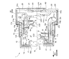
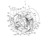
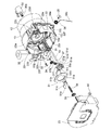
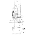
まず、主に図1から図7を参照して、本発明の光学要素位置制御機構を適用したズームレンズ鏡筒1の全体構造を説明する。図1及び図2はズームレンズ鏡筒1の断面を示しており、図1は撮影を行わない収納状態、図2の上半断面はズーム撮影領域のワイド端、図2の下半断面はテレ端をそれぞれ示している。図3と図4は図1の収納状態に対応する斜視図で、図5と図6は図2の撮影状態に対応する斜視図である。   First, the overall structure of the zoom lens barrel 1 to which the optical element position control mechanism of the present invention is applied will be described mainly with reference to FIGS. 1 and 2 show a cross section of the zoom lens barrel 1. FIG. 1 is a storage state in which shooting is not performed, the upper half section of FIG. 2 is the wide end of the zoom shooting area, and the lower half section of FIG. Each edge is shown. 3 and 4 are perspective views corresponding to the storage state of FIG. 1, and FIGS. 5 and 6 are perspective views corresponding to the photographing state of FIG.

ズームレンズ鏡筒1は、物体(被写体)側から順に第1レンズ群LG1、第2レンズ群LG2、絞り兼用のシャッタS、第3レンズ群LG3、ローパスフィルタLPF及びCCD(撮像素子)24を備えた3群タイプの撮像光学系を備えている。この光学系は焦点距離可変のズーム光学系であり、第1レンズ群LG1と第2レンズ群LG2を光学系の撮影光軸Oに沿って所定の軌跡で進退させることによって変倍を行う。また、撮影光軸Oに沿って第3レンズ群LG3を移動させることでフォーカシングを行う。   The zoom lens barrel 1 includes, in order from the object (subject) side, a first lens group LG1, a second lens group LG2, a diaphragm shutter S, a third lens group LG3, a low-pass filter LPF, and a CCD (imaging device) 24. In addition, a three-group imaging optical system is provided. This optical system is a zoom optical system with a variable focal length, and performs zooming by advancing and retracting the first lens group LG1 and the second lens group LG2 along a photographing optical axis O of the optical system along a predetermined locus. Further, focusing is performed by moving the third lens group LG3 along the photographing optical axis O.

ズームレンズ鏡筒1は、第1レンズ群LG1から第3レンズ群LG3までの光学系を内部に可動に支持する固定鏡筒(支持部材)22と、その後部に固定される鏡筒後面板23を備えている。鏡筒後面板23の中央部に形成された開口内には、CCD保持枠62を介してCCD24が保持され、CCD保持枠62の前部に設けたフィルタ保持枠21にローパスフィルタLPFが保持されている。ローパスフィルタLPFとCCD24の間には密封(防塵)用のパッキン61が挟着されている。CCD保持枠62は、鏡筒後面板23に対して傾き調整などが可能に支持されている。   The zoom lens barrel 1 includes a fixed barrel (support member) 22 that movably supports an optical system from the first lens group LG1 to the third lens group LG3, and a barrel rear surface plate 23 that is fixed to the rear portion thereof. It has. The CCD 24 is held in the opening formed at the center of the lens barrel rear plate 23 via the CCD holding frame 62, and the low-pass filter LPF is held by the filter holding frame 21 provided at the front of the CCD holding frame 62. ing. Sealing (dust-proof) packing 61 is sandwiched between the low-pass filter LPF and the CCD 24. The CCD holding frame 62 is supported so as to be capable of adjusting the inclination with respect to the lens barrel rear plate 23.

固定鏡筒22は、撮影光軸Oを囲む円筒状の筒状ハウジング部22aと、ズームモータ32を支持するズームモータ支持部22bと、AFモータ30を支持するAFモータ支持部22cと、該AFモータ支持部22cの前方に位置する前方壁部22dとを有している。筒状ハウジング部22aは、前述した各レンズ群などの光学要素を内部に保持し、ズームレンズ鏡筒1の実質的な外形部を構成している。ズームモータ支持部22b、AFモータ支持部22c及び前方壁部22dは、撮影光軸Oを中心とする半径方向において筒状ハウジング部22aの外側に位置されている。図3ないし図7に示すように、AFモータ支持部22cは、筒状ハウジング部22aの後端部と略同じ光軸方向位置に設けられており、その後面部が鏡筒後面板23によって塞がれる。前方壁部22dは、AFモータ支持部22cに対して光軸方向前方に離間した対向位置に形成されている。   The fixed barrel 22 includes a cylindrical cylindrical housing portion 22a that surrounds the photographing optical axis O, a zoom motor support portion 22b that supports the zoom motor 32, an AF motor support portion 22c that supports the AF motor 30, and the AF And a front wall portion 22d positioned in front of the motor support portion 22c. The cylindrical housing portion 22a holds the optical elements such as the lens groups described above and constitutes a substantial outer shape portion of the zoom lens barrel 1. The zoom motor support portion 22b, the AF motor support portion 22c, and the front wall portion 22d are positioned outside the cylindrical housing portion 22a in the radial direction with the photographing optical axis O as the center. As shown in FIGS. 3 to 7, the AF motor support portion 22 c is provided at substantially the same position in the optical axis direction as the rear end portion of the cylindrical housing portion 22 a, and the rear surface portion is blocked by the lens barrel rear surface plate 23. It is. The front wall portion 22d is formed at a facing position that is spaced forward in the optical axis direction with respect to the AF motor support portion 22c.

第3レンズ群LG3を保持する3群レンズ枠(保持部材)51は、中央のレンズ保持部51aから、撮影光軸Oを挟んで略対称の方向に一対のガイド腕部51b、51cを延設させている。このうち一方のガイド腕部51bの先端部には前後一対のガイド穴51dが形成され、このガイド穴51dに対して、固定鏡筒22と鏡筒後面板23の間に固定された3群ガイド軸(進退ガイド部材)52が摺動自在に挿通されている。図6や図10に示すように、3群ガイド軸52は固定鏡筒22の筒状ハウジング部22aの外側に配置されており、その前端部が前方壁部22dに支持されている。3群ガイド軸52の後端部は、AFモータ支持部22cの下方を通って、鏡筒後面板23に形成した不図示の支持穴に嵌合している。この3群ガイド軸52の案内を受けるために、3群レンズ枠51のガイド腕部51bは、その先端部付近が固定鏡筒22の筒状ハウジング部22aの外方に突出されており、筒状ハウジング部22aにはガイド腕部51bの突出を許す開口部22e(図7)が形成されている。また、3群レンズ枠51の他方のガイド腕部51cの先端部に設けた回転規制突起51eが、固定鏡筒22の内周面に形成した直進ガイド溝22fに対して摺動自在に係合している。3群ガイド軸52の軸線と直進ガイド溝22fの長手方向はそれぞれ撮影光軸Oと平行な方向に向いており、この3群ガイド軸52と直進ガイド溝22fによってガイド穴51dと回転規制突起51eが案内されることによって、3群レンズ枠51は撮影光軸Oと平行な方向に移動可能に直進案内されている。そして、3群レンズ枠51はAFモータ30によって撮影光軸Oに沿って前後に進退移動させることができる。この3群レンズ枠51の駆動機構については後述する。   The third group lens frame (holding member) 51 that holds the third lens group LG3 extends from the central lens holding portion 51a with a pair of guide arm portions 51b and 51c in a substantially symmetrical direction across the photographing optical axis O. I am letting. Of these, a pair of front and rear guide holes 51d is formed at the tip of one guide arm 51b, and a three-group guide fixed between the fixed barrel 22 and the barrel rear plate 23 with respect to the guide hole 51d. A shaft (advance / retreat guide member) 52 is slidably inserted. As shown in FIGS. 6 and 10, the third group guide shaft 52 is disposed outside the cylindrical housing portion 22a of the fixed barrel 22, and the front end portion thereof is supported by the front wall portion 22d. The rear end portion of the third group guide shaft 52 passes below the AF motor support portion 22c and is fitted into a support hole (not shown) formed in the lens barrel rear surface plate 23. In order to receive the guide of the third group guide shaft 52, the guide arm portion 51b of the third group lens frame 51 has a tip portion projecting outward from the cylindrical housing portion 22a of the fixed barrel 22, An opening 22e (FIG. 7) that allows the guide arm portion 51b to protrude is formed in the cylindrical housing portion 22a. A rotation restricting projection 51e provided at the tip of the other guide arm portion 51c of the third group lens frame 51 is slidably engaged with a rectilinear guide groove 22f formed on the inner peripheral surface of the fixed barrel 22. is doing. The axis of the third group guide shaft 52 and the longitudinal direction of the rectilinear guide groove 22f are parallel to the photographing optical axis O, respectively. The guide hole 51d and the rotation restricting projection 51e are formed by the third group guide shaft 52 and the rectilinear guide groove 22f. The third group lens frame 51 is guided in a straight line so as to be movable in a direction parallel to the photographing optical axis O. The third group lens frame 51 can be moved back and forth along the photographing optical axis O by the AF motor 30. A driving mechanism of the third group lens frame 51 will be described later.

固定鏡筒22のズームモータ支持部22bの内部には、ズームモータ32の駆動力をズームギヤ31(図6、図7)に伝達する減速ギヤ列が設けられている。固定鏡筒22の筒状ハウジング部22aの内側に支持されたカム環11の後端部には、ズームギヤ31に噛合する環状ギヤ11aが設けられ、カム環11はズームギヤ31を介してズームモータ32によって回転駆動される。カム環11の環状ギヤ11aから外径方向に突出するガイド突起11bが設けられ、ガイド突起11bは、固定鏡筒22の筒状ハウジング部22aの内周面に形成したカム環制御溝22gに対して摺動可能に係合している。カム環制御溝22gは、撮影光軸Oに対して所定の傾斜を有するリード溝部と、撮影光軸Oを中心とする周方向成分のみからなる周方向溝部とからなる。図1の収納(沈胴)状態と図2の上半断面のワイド端の間は、ズームモータ32によって回転力を付与すると、カム環11は、カム環制御溝22gのリード溝部によってガイド突起11bが案内されて回転しながら光軸方向に移動する。一方、ワイド端とテレ端の間の撮影状態にあるときには、ガイド突起11bがカム環制御溝22gの周方向溝部に位置し、ズームモータ30の駆動に応じてカム環11は光軸方向に移動せずに定位置で回転される。   A reduction gear train that transmits the driving force of the zoom motor 32 to the zoom gear 31 (FIGS. 6 and 7) is provided inside the zoom motor support 22b of the fixed barrel 22. An annular gear 11 a that meshes with the zoom gear 31 is provided at the rear end of the cam ring 11 that is supported inside the cylindrical housing portion 22 a of the fixed barrel 22, and the cam ring 11 is connected to the zoom motor 32 via the zoom gear 31. It is rotationally driven by. A guide projection 11b projecting from the annular gear 11a of the cam ring 11 in the outer diameter direction is provided, and the guide projection 11b is formed with respect to a cam ring control groove 22g formed on the inner peripheral surface of the cylindrical housing portion 22a of the fixed barrel 22. Are slidably engaged. The cam ring control groove 22g includes a lead groove portion having a predetermined inclination with respect to the photographing optical axis O and a circumferential groove portion including only a circumferential component centered on the photographing optical axis O. When the rotational force is applied by the zoom motor 32 between the storage (collapsed) state of FIG. 1 and the wide end of the upper half section of FIG. 2, the cam ring 11 has the guide protrusion 11b formed by the lead groove portion of the cam ring control groove 22g. It moves in the direction of the optical axis while being guided and rotated. On the other hand, when the photographing state is between the wide end and the tele end, the guide protrusion 11b is positioned in the circumferential groove portion of the cam ring control groove 22g, and the cam ring 11 moves in the optical axis direction according to the driving of the zoom motor 30. Rotated in place without

固定鏡筒22の筒状ハウジング部22aの内側には、カム環11を挟む態様で第1繰出筒13と直進案内環10が支持されている。第1繰出筒13は、筒状ハウジング部22aの内周面に形成した直進案内溝22hに対する直進案内突起13aの係合関係により光軸方向に直進案内されており、直進案内環10は、筒状ハウジング部22aの内周面に形成した直進案内溝22iに対する直進案内突起10aの係合関係により光軸方向に直進案内されている。第1繰出筒13と直進案内環10はそれぞれ、カム環11に対しては、相対回転は可能で光軸方向に共に移動するように結合されている。   On the inner side of the cylindrical housing portion 22a of the fixed barrel 22, the first feeding cylinder 13 and the rectilinear guide ring 10 are supported so as to sandwich the cam ring 11. The first feed cylinder 13 is guided in a straight line in the optical axis direction by the engagement relationship of the straight guide groove 13h with a straight guide groove 22h formed on the inner peripheral surface of the cylindrical housing portion 22a. Is guided linearly in the optical axis direction by the engagement relationship of the rectilinear guide protrusion 10a with the rectilinear guide groove 22i formed on the inner peripheral surface of the housing 22a. The first feeding cylinder 13 and the linear guide ring 10 are coupled to the cam ring 11 so as to be capable of relative rotation and move together in the optical axis direction.

直進案内環10は、カム環11の内側に位置する直進案内キー10b(図2)によって、2群レンズ移動枠8を光軸方向に直進案内している。2群レンズ移動枠8の内部には、2群レンズ保持枠部6を介して第2レンズ群LG2が支持されている。また、第1繰出筒13の内周面には撮影光軸Oと平行な直進案内溝13bが形成され、該直進案内溝13bに対して第2繰出筒12の直進案内突起12aが摺動自在に係合しており、第2繰出筒12も光軸方向へ直進案内されている。第2繰出筒12の内部には、1群レンズ保持枠部4を介して第1レンズ群LG1が支持されている。   The rectilinear guide ring 10 guides the second group lens moving frame 8 rectilinearly in the optical axis direction by a rectilinear guide key 10b (FIG. 2) located inside the cam ring 11. A second lens group LG <b> 2 is supported inside the second group lens moving frame 8 via a second group lens holding frame portion 6. Further, a rectilinear guide groove 13b parallel to the photographing optical axis O is formed on the inner peripheral surface of the first feed cylinder 13, and the rectilinear guide protrusion 12a of the second feed cylinder 12 is slidable in the rectilinear guide groove 13b. The second feeding cylinder 12 is also guided in a straight line in the optical axis direction. The first lens group LG <b> 1 is supported inside the second feeding cylinder 12 via the first group lens holding frame portion 4.

カム環11の内周面に形成した2群制御カム溝11cに対し、2群レンズ移動枠8の外周面に設けた2群用カムフォロア8aが係合している。2群レンズ移動枠8は直進案内環10を介して光軸方向に直進案内されているため、カム環17が回転すると、2群制御カム溝11cの形状に従って、2群レンズ移動枠8すなわち第2レンズ群LG2が光軸方向へ所定の軌跡で移動する。   A second group cam follower 8 a provided on the outer peripheral surface of the second group lens moving frame 8 is engaged with the second group control cam groove 11 c formed on the inner peripheral surface of the cam ring 11. Since the second group lens moving frame 8 is linearly guided in the optical axis direction via the straight guide ring 10, when the cam ring 17 rotates, the second group lens moving frame 8, i.e., the first group moving frame 8 is moved according to the shape of the second group control cam groove 11c. The two lens group LG2 moves along a predetermined locus in the optical axis direction.

第2繰出筒12は内径方向に突出する1群用カムフォロア12bを有し、この1群用カムフォロア12bが、カム環11の外周面に形成した1群制御カム溝11dに摺動可能に嵌合している。第2繰出筒12は第1繰出筒13を介して光軸方向に直進案内されているため、カム環11が回転すると、1群制御カム溝11dの形状に従って、第2繰出筒12すなわち第1レンズ群LG1が光軸方向へ所定の軌跡で移動する。   The second feeding cylinder 12 has a first group cam follower 12b protruding in the inner diameter direction, and the first group cam follower 12b is slidably fitted in a first group control cam groove 11d formed on the outer peripheral surface of the cam ring 11. is doing. Since the second feeding cylinder 12 is guided linearly in the direction of the optical axis via the first feeding cylinder 13, when the cam ring 11 rotates, the second feeding cylinder 12, that is, the first feeding cylinder 12 according to the shape of the first group control cam groove 11d. The lens group LG1 moves along a predetermined locus in the optical axis direction.

2群レンズ移動枠8と第2繰出筒12は、群間付勢ばね27によって、互いに離間する方向に付勢されており、2群制御カム溝11cと2群用カムフォロア8aの間と、1群用カムフォロア12bと1群制御カム溝11dの間での嵌合精度を高めている。   The second group lens moving frame 8 and the second feeding cylinder 12 are urged in a direction away from each other by an intergroup urging spring 27, between the second group control cam groove 11c and the second group cam follower 8a, and 1 The fitting accuracy between the group cam follower 12b and the first group control cam groove 11d is increased.

2群レンズ移動枠8の内側には、シャッタSを有するシャッタブロック15が支持されている。2群レンズ移動枠8と、該2群レンズ移動枠8の後部に設けた後方規制部材5には、撮影光軸Oと平行な方向へ向けて対をなすガイド突起8b、5aが互いに接近するように突設されており、このガイド突起8b、5aに対してシャッタブロック15は光軸方向に摺動可能に支持されている。   A shutter block 15 having a shutter S is supported inside the second group lens moving frame 8. Guide protrusions 8b and 5a that make a pair in the direction parallel to the photographing optical axis O approach each other on the second group lens moving frame 8 and the rear regulating member 5 provided at the rear of the second group lens moving frame 8. The shutter block 15 is supported so as to be slidable in the optical axis direction with respect to the guide protrusions 8b and 5a.

第2繰出筒12の前端部には化粧板16が固定され、該化粧板16における第1レンズ群LG1前方の撮影開口16aを開閉するバリヤ部材17が設けられている。   A decorative plate 16 is fixed to the front end portion of the second feeding cylinder 12, and a barrier member 17 that opens and closes a photographing opening 16 a in front of the first lens group LG <b> 1 on the decorative plate 16 is provided.

以上の構造からなるズームレンズ鏡筒1は次のように動作する。図1に示す鏡筒収納状態では、図2の撮影状態よりも撮影光軸方向の光学系の長さ(第1レンズ群LG1の物体側の面からCCD24の撮像面までの距離)が短くなっている。この鏡筒収納状態においてカメラに設けたメインスイッチがオンされると、ズームモータ32が鏡筒繰出方向に駆動される。ズームモータ32によりズームギヤ31が回転駆動され、固定鏡筒22のカム環制御溝22gのリード溝部にガイド突起11bが案内されて、カム環11が光軸方向前方へ回転繰出される。直進案内環10と第1繰出筒13は、カム環11と共に前方に直進移動する。カム環11が回転すると、その内側では、直進案内環10を介して直進案内された2群レンズ移動枠8が、2群用カムフォロア8aと2群制御カム溝11cの関係によって光軸方向に所定の軌跡で移動される。また、カム環11が回転すると、該カム環11の外側では、第1繰出筒13を介して直進案内された第2繰出筒12が、1群用カムフォロア12bと1群制御カム溝11dの関係によって光軸方向に所定の軌跡で移動される。   The zoom lens barrel 1 having the above structure operates as follows. In the lens barrel storage state shown in FIG. 1, the length of the optical system in the photographic optical axis direction (distance from the object side surface of the first lens group LG1 to the imaging surface of the CCD 24) is shorter than in the imaging state of FIG. ing. When the main switch provided in the camera is turned on in the lens barrel storage state, the zoom motor 32 is driven in the lens barrel feeding direction. The zoom gear 31 is rotationally driven by the zoom motor 32, the guide protrusion 11 b is guided to the lead groove portion of the cam ring control groove 22 g of the fixed barrel 22, and the cam ring 11 is rotated and fed forward in the optical axis direction. The rectilinear guide ring 10 and the first feed cylinder 13 move forward together with the cam ring 11. When the cam ring 11 rotates, on the inner side, the second group lens moving frame 8 guided linearly through the straight guide ring 10 is predetermined in the optical axis direction due to the relationship between the second group cam follower 8a and the second group control cam groove 11c. It is moved by the trajectory. Further, when the cam ring 11 rotates, the second feeding cylinder 12 guided linearly through the first feeding cylinder 13 on the outside of the cam ring 11 is related to the first group cam follower 12b and the first group control cam groove 11d. Is moved along a predetermined locus in the optical axis direction.

すなわち、鏡筒収納状態からの第1レンズ群LG1と第2レンズ群LG2の繰出量はそれぞれ、前者が、固定鏡筒22に対するカム環11の前方移動量と、該カム環11に対する第2繰出筒12のカム繰出量との合算値として決まり、後者が、固定鏡筒22に対するカム環11の前方移動量と、該カム環11に対する2群レンズ移動枠8のカム繰出量との合算値として決まる。ズーミングは、この第1レンズ群LG1と第2レンズ群LG2が互いの空気間隔を変化させながら撮影光軸O上を移動することにより行われる。図1の収納状態から鏡筒繰出を行うと、まず図2の上半断面に示すワイド端の繰出状態になり、さらにズームモータ32を鏡筒繰出方向に駆動させると、図2の下半断面に示すテレ端の繰出状態となる。テレ端とワイド端の間のズーム領域では、カム環11は、ガイド突起11bがカム環制御溝22gの周方向溝部内に位置することにより前述の定位置回転のみを行い、光軸方向へは進退しない。メインスイッチをオフすると、ズームモータ32が鏡筒収納方向に駆動され、ズームレンズ鏡筒1は以上の繰出動作とは逆の収納動作を行い、図1の収納状態になる。   That is, the first lens group LG1 and the second lens group LG2 are fed out from the lens barrel retracted state by the former moving amount of the cam ring 11 with respect to the fixed barrel 22 and the second feeding amount with respect to the cam ring 11, respectively. It is determined as a sum of the cam feed amount of the cylinder 12 and the latter is a sum of the amount of forward movement of the cam ring 11 with respect to the fixed barrel 22 and the cam feed amount of the second group lens moving frame 8 with respect to the cam ring 11. Determined. Zooming is performed by moving the first lens group LG1 and the second lens group LG2 on the photographing optical axis O while changing the air interval between them. When the lens barrel is extended from the housed state of FIG. 1, first, the wide end extended state shown in the upper half section of FIG. 2 is obtained, and when the zoom motor 32 is further driven in the lens barrel extending direction, the lower half section of FIG. As shown in FIG. In the zoom region between the tele end and the wide end, the cam ring 11 performs only the above-mentioned fixed position rotation by the guide protrusion 11b being positioned in the circumferential groove portion of the cam ring control groove 22g, and in the optical axis direction. Do not advance or retreat. When the main switch is turned off, the zoom motor 32 is driven in the lens barrel storage direction, and the zoom lens barrel 1 performs a storage operation opposite to the above-described feeding operation, and enters the storage state of FIG.

なお、ズームレンズ鏡筒1における図2の撮影状態では、シャッタSが第2レンズ群LG2の後方に位置される一方、図1の収納状態では、シャッタブロック15が、2群レンズ移動枠8内での相対的な光軸方向位置を前方に移動させ、第2レンズ群LG2とシャッタSが一部重なる状態になる。   In the photographing state of FIG. 2 in the zoom lens barrel 1, the shutter S is positioned behind the second lens group LG2, while in the retracted state of FIG. The relative position in the optical axis direction is moved forward, so that the second lens group LG2 and the shutter S partially overlap.

第3レンズ群LG3は、以上のズームモータ32による第1及び第2のレンズ群LG1、LG2の駆動とは独立して、AFモータ30によって撮影光軸Oに沿って前後移動させることができる。そして、ワイド端からテレ端までの撮影可能状態にあるとき、測距手段によって得られた被写体距離情報に応じてAFモータ30を駆動することにより、第3レンズ群LG3を支持する3群レンズ枠51が撮影光軸Oに沿って移動してフォーカシングが実行される。   The third lens group LG3 can be moved back and forth along the photographing optical axis O by the AF motor 30, independently of the driving of the first and second lens groups LG1 and LG2 by the zoom motor 32 described above. Then, when the photographing from the wide end to the tele end is possible, the third group lens frame that supports the third lens group LG3 by driving the AF motor 30 according to the subject distance information obtained by the distance measuring means. 51 is moved along the photographing optical axis O to perform focusing.

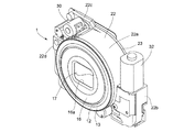
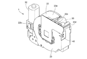
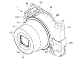
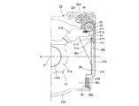
続いて、3群レンズ枠51の位置制御機構の細部を説明する。前述のように、固定鏡筒22には、筒状ハウジング部22aの外側にAFモータ支持部22cが形成され、このAFモータ支持部22cの前方に対向させて前方壁部22dが形成されている。AFモータ30は、固定ねじ33によってAFモータ支持部22cの前面側に固定され、該AFモータ30の回転軸に設けたピニオン30aがAFモータ支持部22cの後面側に突出する。AFモータ支持部22cの後面側には、ピニオン30aに噛合する減速ギヤ34と、該減速ギヤ34に噛合する送りねじギヤ35が軸支されていて、AFモータ30の回転軸の回転は、この減速ギヤ列を介して、送りねじギヤ35と一体に回転する送りねじ36に伝達される。送りねじ36は、その前端部が固定鏡筒22の前方壁部22dに形成した軸穴により軸支され、後端部が鏡筒後面板23に形成した軸穴により軸支され、この軸支状態において送りねじ36は、撮影光軸Oと略平行な回転中心によって回転自在となる。   Next, details of the position control mechanism of the third group lens frame 51 will be described. As described above, the fixed barrel 22 is formed with the AF motor support portion 22c outside the cylindrical housing portion 22a, and the front wall portion 22d is formed facing the front of the AF motor support portion 22c. . The AF motor 30 is fixed to the front surface side of the AF motor support portion 22c by a fixing screw 33, and a pinion 30a provided on the rotation shaft of the AF motor 30 projects to the rear surface side of the AF motor support portion 22c. A reduction gear 34 meshing with the pinion 30a and a feed screw gear 35 meshing with the reduction gear 34 are pivotally supported on the rear surface side of the AF motor support portion 22c. It is transmitted to the feed screw 36 that rotates integrally with the feed screw gear 35 via the reduction gear train. The front end portion of the feed screw 36 is pivotally supported by a shaft hole formed in the front wall portion 22d of the fixed barrel 22, and the rear end portion is pivotally supported by a shaft hole formed in the lens barrel rear surface plate 23. In this state, the feed screw 36 is rotatable by a rotation center substantially parallel to the photographing optical axis O.

3群レンズ枠51のガイド腕部51bの先端部には、送りねじ36を挿通させる貫通穴が形成されたナット当付部51fが形成されており、このナット当付部51fの前方に位置させて、送りねじ36に螺合するねじ穴を有するAFナット37が設けられている。AFナット37は、回り止め用の凹部37a(図7)を3群レンズ枠51の回り止め突起51g(図8)に係合させ、また回り止め用の凸部37bを固定鏡筒22の回り止め用の凹部(不図示)に係合させることにより回転規制されており、送りねじ36を正逆に回転させることにより、送りねじ36と連れ回りすることなく撮影光軸Oと平行に進退移動される。3群レンズ枠51のガイド腕部51bの先端部にはさらに、前後一対のガイド穴51dの間に位置させて、L字状のばね掛け突起(突起部)51hが突設されている。   A nut abutting portion 51f having a through hole through which the feed screw 36 is inserted is formed at the distal end portion of the guide arm portion 51b of the third group lens frame 51, and is positioned in front of the nut abutting portion 51f. An AF nut 37 having a screw hole that is screwed into the feed screw 36 is provided. The AF nut 37 engages a rotation-preventing concave portion 37 a (FIG. 7) with a rotation-preventing projection 51 g (FIG. 8) of the third group lens frame 51, and a rotation-preventing convex portion 37 b around the fixed barrel 22. The rotation is restricted by engaging with a recess (not shown) for stopping, and by moving the feed screw 36 forward and backward, it moves forward and backward in parallel with the photographic optical axis O without rotating with the feed screw 36. Is done. Further, an L-shaped spring-hanging projection (projection) 51 h is projected from the tip of the guide arm portion 51 b of the third group lens frame 51 so as to be positioned between the pair of front and rear guide holes 51 d.

3群レンズ枠51に対して撮影光軸Oに沿う移動方向の付勢力を与える付勢手段として、3群レンズ付勢ばね(ばね部材)38が設けられている。3群レンズ付勢ばね38はトーションばねであり、そのコイル部38aが、固定鏡筒22に設けたばね支持突起22jに支持される。ばね支持突起22jは、筒状ハウジング部22aの外側に、撮影光軸Oと略直交する側方へ軸線を向けて形成された円筒状の突起であり、該ばね支持突起22jの中心に形成されたねじ穴に対してばね留めねじ39を固定することによって、ばね支持突起22jの円筒状外面に対して3群レンズ付勢ばね38のコイル部38aが抜け止めされた状態で保持される。この保持状態のコイル部38aの軸線は、ばね支持突起22jの軸線と概ね一致する。   A third group lens biasing spring (spring member) 38 is provided as a biasing unit that applies a biasing force in the moving direction along the photographing optical axis O to the third group lens frame 51. The third group lens biasing spring 38 is a torsion spring, and its coil portion 38 a is supported by a spring support protrusion 22 j provided on the fixed barrel 22. The spring support protrusion 22j is a cylindrical protrusion formed on the outside of the cylindrical housing portion 22a with the axis line directed to the side substantially orthogonal to the photographing optical axis O, and is formed at the center of the spring support protrusion 22j. By fixing the spring retaining screw 39 to the threaded hole, the coil portion 38a of the third group lens biasing spring 38 is held against the cylindrical outer surface of the spring support projection 22j. The axis of the coil portion 38a in the holding state substantially coincides with the axis of the spring support protrusion 22j.

3群レンズ付勢ばね38は、コイル部38aから外径方向に向けて、短い支持腕部(第2の腕部)38bと、長い付勢腕部(付勢手段、第1の腕部)38cを延設させている。このうち支持腕部38bは、ばね支持突起22jの近傍に位置させて固定鏡筒22に形成されたばね掛け突起22k(図12)に掛けられている。一方、付勢腕部38cは、3群レンズ枠51のばね掛け突起51hに掛けられている。付勢腕部38cは、コイル部38aの軸線に略一致する揺動中心軸38xを中心(支点)として揺動することが可能な(すなわち撮影光軸Oと概ね平行な揺動平面内で揺動可能な)揺動着力部であって、ばね掛け突起51hに掛けられていない自由状態では図12に「38c(F)」で示す方向を向いている。そして、この自由状態から付勢腕部38cを図12中の反時計方向に約半回転させて、該付勢腕部38cの先端部付近をばね掛け突起51hの光軸方向後方の面に当て付けることにより、3群レンズ付勢ばね38の撓み(ねじれ)量が大きくなり、その撓み解消方向の力は、付勢腕部38cがばね掛け突起51hを光軸方向前方へ押圧する荷重として作用する。すなわち、付勢腕部38cを介して3群レンズ枠51に対して光軸方向前方への付勢力が与えられる着力状態となる。   The third group lens biasing spring 38 includes a short support arm portion (second arm portion) 38b and a long biasing arm portion (biasing means, first arm portion) from the coil portion 38a toward the outer diameter direction. 38c is extended. Of these, the support arm portion 38b is hung on a spring hooking protrusion 22k (FIG. 12) formed on the fixed lens barrel 22 in the vicinity of the spring support protrusion 22j. On the other hand, the urging arm portion 38 c is hung on the spring hooking protrusion 51 h of the third group lens frame 51. The urging arm portion 38c can oscillate around an oscillation center axis 38x substantially coincident with the axis of the coil portion 38a (ie, a fulcrum) (that is, oscillate in an oscillation plane substantially parallel to the photographing optical axis O). In a free state that is not swingable on the spring hooking protrusion 51h, it is directed in the direction indicated by "38c (F)" in FIG. Then, from this free state, the urging arm portion 38c is rotated about half a counterclockwise in FIG. 12, and the vicinity of the tip end portion of the urging arm portion 38c is applied to the rear surface in the optical axis direction of the spring projection 51h. As a result, the amount of bending (twisting) of the third group lens urging spring 38 is increased, and the force in the sag-removing direction acts as a load for the urging arm portion 38c to press the spring hooking protrusion 51h forward in the optical axis direction. To do. That is, it is in an applied state in which an urging force forward in the optical axis direction is applied to the third group lens frame 51 via the urging arm portion 38c.

このようにして3群レンズ付勢ばね38から光軸方向前方への付勢力を与えられた3群レンズ枠51は、ナット当付部51fがAFナット37に当て付くことによって、その前方への移動が規制される。すなわち、図8、図9及び図12に示すように、3群レンズ枠51は、3群レンズ付勢ばね38の付勢力によってナット当付部51fをAFナット37に当接させた状態で保持され、3群レンズ枠51の光軸方向への前後位置はAFナット37に依存して決まる。前述の通り、AFナット37は、AFモータ30のピニオン30aを正逆に回転駆動することにより、送りねじ36によって撮影光軸Oと平行な方向へ進退移動されるため、結果として、3群レンズ枠51の光軸方向位置は、AFモータ30の駆動方向と駆動量に応じて制御される。例えば、AFモータ30によって前方にAFナット37を移動させると、AFナット37の移動分だけ、3群レンズ付勢ばね38の付勢力によって3群レンズ枠51が追随して前方に移動する。逆に、前方の移動位置からAFナット37を後方に移動させると、該AFナット37がナット当付部51fを押し込み、3群レンズ枠51は3群レンズ付勢ばね38の付勢力に抗して後方へ移動される。   In this way, the third group lens frame 51 applied with the urging force forward in the optical axis direction from the third group lens urging spring 38 is moved forward by the nut abutting portion 51f against the AF nut 37. Movement is restricted. That is, as shown in FIGS. 8, 9 and 12, the third group lens frame 51 is held in a state where the nut abutting portion 51f is in contact with the AF nut 37 by the urging force of the third group lens urging spring 38. The front and rear positions of the third group lens frame 51 in the optical axis direction are determined depending on the AF nut 37. As described above, the AF nut 37 is moved forward and backward in the direction parallel to the photographing optical axis O by the feed screw 36 by rotating the pinion 30a of the AF motor 30 in the forward and reverse directions. The position of the frame 51 in the optical axis direction is controlled according to the driving direction and driving amount of the AF motor 30. For example, when the AF nut 37 is moved forward by the AF motor 30, the third group lens frame 51 is moved forward by the urging force of the third group lens urging spring 38 by the amount of movement of the AF nut 37. On the other hand, when the AF nut 37 is moved backward from the forward movement position, the AF nut 37 pushes the nut abutting portion 51f, and the third group lens frame 51 resists the biasing force of the third group lens biasing spring 38. Moved backwards.

固定鏡筒22には、AFモータ30による3群レンズ枠51の光軸方向の後方移動端を検出する原点位置検出センサ40が設けられている。原点位置検出センサ40は、透過型フォトインタラプタからなり、二股状の投光部と受光部の間に3群レンズ枠51のセンサ通過板51iが位置した状態が、該3群レンズ枠51の後方移動端であると検知される。AFモータ30はステッピングモータからなり、フォーカシングに際しての第3レンズ群LG3の移動量は、この後方移動端を原点位置としたAFモータ30の駆動ステップ数として演算される。   The fixed barrel 22 is provided with an origin position detection sensor 40 that detects a rearward movement end of the third group lens frame 51 in the optical axis direction by the AF motor 30. The origin position detection sensor 40 is composed of a transmissive photo interrupter, and the state in which the sensor passage plate 51i of the third group lens frame 51 is located between the bifurcated light projecting portion and the light receiving portion is behind the third group lens frame 51. Detected as moving end. The AF motor 30 is a stepping motor, and the amount of movement of the third lens group LG3 during focusing is calculated as the number of driving steps of the AF motor 30 with the rearward movement end as the origin position.

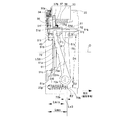
図12に実線で示しているのが、AFモータ30に制御される可動範囲における3群レンズ枠51の後方移動端であり、同図に二点鎖線で示しているのが、同可動範囲における3群レンズ枠51の前方移動端である。この3群レンズ枠51の光軸方向の位置変化に応じた、3群レンズ付勢ばね38の荷重の変動を図14(a)に示した。3群レンズ枠51が後方移動端に位置するときと、前方移動端に位置するときの、自由状態からの付勢腕部38cの揺動角(3群レンズ付勢ばね38の撓み量)の大きさはそれぞれθmin、θmaxで表される。そして、この付勢腕部38cの揺動角θmin、θmaxに対応する3群レンズ付勢ばねの荷重がFmin、Fmaxとなる。図12から分かるように、3群レンズ付勢ばね38における着力状態での最小揺動角θminと最大揺動角θmaxの間の変位量θvは、自由状態から着力状態になるまでの最小揺動角θminに比べて遙かに小さい。そのため、3群レンズ枠51の可動範囲における3群レンズ付勢ばね38の最小荷重Fminから最大荷重Fmaxまでの変動は小さく抑えられる。   A solid line in FIG. 12 shows the rear moving end of the third group lens frame 51 in the movable range controlled by the AF motor 30, and a two-dot chain line in FIG. 12 shows in the movable range. This is the front moving end of the third group lens frame 51. FIG. 14A shows the variation in the load of the third group lens urging spring 38 according to the change in the position of the third group lens frame 51 in the optical axis direction. When the third group lens frame 51 is located at the rear moving end and when the third group lens frame 51 is located at the front moving end, the swing angle of the urging arm portion 38c from the free state (the amount of deflection of the third group lens urging spring 38). The magnitudes are represented by θmin and θmax, respectively. The loads of the third group lens urging springs corresponding to the swing angles θmin and θmax of the urging arm portions 38c are Fmin and Fmax. As can be seen from FIG. 12, the displacement θv between the minimum swing angle θmin and the maximum swing angle θmax in the applied state in the third group lens biasing spring 38 is the minimum swing from the free state to the applied state. It is much smaller than the angle θmin. Therefore, the fluctuation from the minimum load Fmin to the maximum load Fmax of the third group lens biasing spring 38 in the movable range of the third group lens frame 51 is suppressed to a small value.

3群レンズ付勢ばね38に代えて、撮影光軸Oと平行な方向に伸縮する引張ばね38′を配した比較例を図13に示す。この引張ばね38′は、一端部が3群レンズ枠51′のばね掛け突起51h′に掛けられ、他端部が固定鏡筒22′のばね掛け突起22j′に掛けられている。3群レンズ枠51′は、3群ガイド軸52′に沿って撮影光軸Oと平行に進退移動可能であり、AFモータ30′に制御される可動範囲内における3群レンズ枠51′の後方移動端を実線、前方移動端を二点鎖線で示している。また、3群レンズ枠51′の前後それぞれの移動端における、固定鏡筒22′側のばね掛け突起22j′との係合位置を基準にした引張ばね38′の長さをLmin、Lmaxで示している。固定位置のばね掛け突起22j′は前方に位置しているので、3群レンズ枠51′の後方移動端で引張ばね38′が最も長く(Lmax)なる。Lfは、自由状態での引張ばね38′の長さである。   FIG. 13 shows a comparative example in which a tension spring 38 ′ that expands and contracts in a direction parallel to the photographing optical axis O is provided in place of the third group lens biasing spring 38. One end of the tension spring 38 ′ is hooked on the spring hooking protrusion 51 h ′ of the third group lens frame 51 ′, and the other end is hooked on the spring hooking protrusion 22 j ′ of the fixed barrel 22 ′. The third group lens frame 51 'is movable back and forth along the third group guide shaft 52' in parallel with the photographic optical axis O, and behind the third group lens frame 51 'within a movable range controlled by the AF motor 30'. The moving end is indicated by a solid line, and the forward moving end is indicated by a two-dot chain line. In addition, the lengths of the tension springs 38 'with reference to the engaging positions with the spring engaging projections 22j' on the fixed barrel 22 'side at the respective front and rear moving ends of the third group lens frame 51' are indicated by Lmin and Lmax. ing. Since the spring-hanging projection 22j 'at the fixed position is located at the front, the tension spring 38' is the longest (Lmax) at the rearward movement end of the third lens group frame 51 '. Lf is the length of the tension spring 38 'in the free state.

図13の比較例における引張ばね38′による荷重の変動を、図14(b)に示した。同図のFmin′、Fmax′はそれぞれ、引張ばね38′の長さがLmin、Lmaxであるときのばね荷重である。図13から分かるように、引張ばね38′は、自由状態での長さLFから3群レンズ枠51′への着力状態での最小長さLminになるまでの変位量Lv1よりも、該着力状態での最小長さLminと最大長さLmaxの間の変位量Lv2の方が大幅に大きくなっている。引張ばね38′の荷重の大きさはその長さ変化に比例して変動するため、引張ばね38′では、最小長さLmin時の荷重Fmin′と最大長さLmax時の荷重Fmax′の差が非常に大きくなってしまう。そして、最大荷重Fmax′に対応した強力なAFモータ30′が必要になる。   FIG. 14B shows the fluctuation of the load due to the tension spring 38 'in the comparative example of FIG. Fmin ′ and Fmax ′ in the figure are spring loads when the length of the tension spring 38 ′ is Lmin and Lmax, respectively. As can be seen from FIG. 13, the tension spring 38 ′ is in an applied state more than the displacement amount Lv 1 from the length LF in the free state to the minimum length Lmin in the applied state to the third group lens frame 51 ′. The displacement amount Lv2 between the minimum length Lmin and the maximum length Lmax is significantly larger. Since the magnitude of the load of the tension spring 38 'varies in proportion to the change in its length, the tension spring 38' has a difference between the load Fmin 'at the minimum length Lmin and the load Fmax' at the maximum length Lmax. It becomes very big. A powerful AF motor 30 'corresponding to the maximum load Fmax' is required.

荷重変動を抑制するため、すなわち最長時と最短時の長さ変化を相対的に小さくするために、引張ばね38′の自由状態での長さを伸ばすことが考えられる。しかし、引張ばね38′を長くすればそれだけ広い配設スペースが必要となり、鏡筒小型化の要求に反してしまう。図13の比較例は、引張ばね38′を除いては図12の実施形態と共通の構造を有しており、仮に引張ばね38′の全長を長くさせようとすると、収納状態の鏡筒前端部位置(固定鏡筒22′の前端位置にほぼ等しい)よりも前方(図13中の右側)にばね掛け突起22j′を位置させなければならない。つまり、長くした引張ばね38′を配置しようとすると、鏡筒収納長が大きくなってしまう。その意味において、図13の比較例における引張ばね38′は、鏡筒の構造上可能な最大の長さを既に与えられているのであり、現状の鏡筒収納サイズを維持しつつ、図14(b)に示される以上に荷重変動を小さく抑えることは困難であり、鏡筒の小型化と荷重変動の抑制の要求を同時に満たすことができない。   In order to suppress the load fluctuation, that is, to make the change in length between the longest time and the shortest time relatively small, it is conceivable to extend the length of the tension spring 38 'in the free state. However, if the tension spring 38 'is made longer, a larger installation space is required, which is against the demand for downsizing the lens barrel. The comparative example of FIG. 13 has the same structure as that of the embodiment of FIG. 12 except for the tension spring 38 ′. If the total length of the tension spring 38 ′ is increased, the front end of the lens barrel in the stored state will be described. The spring hooking protrusion 22j ′ must be positioned ahead (right side in FIG. 13) of the part position (substantially equal to the front end position of the fixed barrel 22 ′). That is, if an attempt is made to arrange the elongated tension spring 38 ', the lens barrel storage length becomes large. In that sense, the tension spring 38 ′ in the comparative example of FIG. 13 has already been given the maximum possible length in terms of the structure of the lens barrel, and FIG. 14 ( It is difficult to keep the load fluctuation smaller than shown in b), and it is impossible to satisfy the demands for reducing the size of the lens barrel and suppressing the load fluctuation at the same time.

また、3群レンズ枠51′の可動範囲を小さくすれば(後方移動端を図13の実線位置よりも前寄りに設定すれば)、引張ばね38′の自由長を伸ばさずに最大荷重を小さくすることはできるが、レンズ移動量が制限されて所要の光学性能が得られなくなるおそれがあるため、実際的ではない。   Further, if the movable range of the third group lens frame 51 'is reduced (if the rearward movement end is set in front of the solid line position in FIG. 13), the maximum load is reduced without increasing the free length of the tension spring 38'. However, it is not practical because the amount of lens movement is limited and the required optical performance may not be obtained.

なお、図13の比較例では引張ばね38′を用いているが、これを圧縮ばねに置き換えても同様の問題がある。すなわち、引張ばねと圧縮ばねのいずれであっても、3群レンズ枠51′と固定部材(固定鏡筒22′)との間を、該3群レンズ枠51′の進退方向に伸縮するばね部材で直接に接続した付勢構造では、コンパクト化と荷重変動の抑制とを両立させることが難しかった。   Although the tension spring 38 'is used in the comparative example of FIG. 13, there is a similar problem even if this is replaced with a compression spring. That is, regardless of whether the spring is a tension spring or a compression spring, a spring member that expands and contracts between the third group lens frame 51 'and the fixed member (fixed barrel 22') in the advancing and retracting direction of the third group lens frame 51 '. In the urging structure that is directly connected with the, it is difficult to achieve both compactness and suppression of load fluctuation.

これに対して、3群レンズ枠51の付勢手段に3群レンズ付勢ばね38を用いた本実施形態の構成では、図14(a)と図14(b)の比較から分かるように、同等の配置スペースに設けられる付勢手段でありながら、その荷重変動は比較例に対して遙かに小さく、ばねの最大荷重も比較例に比べて小さい。その結果、3群レンズ枠51の駆動に必要とされるエネルギーが低いレベルで平均化され、AFモータ30における消費電力を抑えることが可能となった。別言すれば、省電力タイプのAFモータ30の採用が可能となった。また、3群レンズ枠51の移動に応じた荷重変動が小さいので、移動範囲の全域に亘ってスムーズに駆動させることができ、AFモータ30からの駆動力を伝達する駆動機構からの異音も発生しにくい。   On the other hand, in the configuration of the present embodiment in which the third group lens biasing spring 38 is used as the biasing means of the third group lens frame 51, as can be seen from the comparison between FIG. 14A and FIG. Although it is an urging means provided in an equivalent arrangement space, its load fluctuation is much smaller than that of the comparative example, and the maximum load of the spring is also smaller than that of the comparative example. As a result, the energy required for driving the third group lens frame 51 is averaged at a low level, and the power consumption in the AF motor 30 can be suppressed. In other words, the power-saving AF motor 30 can be used. Further, since the load fluctuation according to the movement of the third group lens frame 51 is small, it can be driven smoothly over the entire moving range, and abnormal noise from the driving mechanism that transmits the driving force from the AF motor 30 is also generated. Hard to occur.

前述のように、3群レンズ付勢ばね38においては、着力状態の作用区間(3群レンズ枠51の前後移動端の間)での付勢腕部38cの揺動変位量(θv)が、自由状態から3群レンズ枠51への着力(係合)状態になるまでの付勢腕部38cの揺動変位量(θmin)よりも小さく、θv/θmin<1という関係になっており、これによって着力状態における荷重変動が小さく抑えられている。図12に示す態様では、θminの大きさが約半回転に設定されているが、分母にあたるθminの値を大きくすることで(θminの増加に応じてθmaxも大きくなるためθvは一定)、着力状態の作用区間での付勢腕部38cの揺動変位量θvを相対的に小さくさせ、3群レンズ付勢ばね38の最大荷重と最小荷重の差をより一層小さくさせることができる。θv/θmin<1を満たすことで荷重変動の抑制には有効であるが、より好ましくは、θv/θmin<0.5を満たすようにすると、顕著な効果が得られる。θminの値を大きくする具体的な手法として、付勢腕部38cを自由状態から1回転以上ねじってばね掛け突起51hに係合させてもよい。トーションばねからなる3群レンズ付勢ばね38は、コイル部38aを中心とした回転方向の撓み量を増大させてもその大きさは実質的に変わらないので、比較例として挙げた引張ばねや圧縮ばねの自由状態長を伸ばす場合とは異なり、その配設スペースを増大させる必要はない。なお、ばねを構成する鋼線の太さなどの条件が同一であれば、自由状態から着力状態になるまでの3群レンズ付勢ばね38の撓み量を大きくすれば、荷重も平均的に増大するため、最大荷重が過大にならない範囲内で撓み量が設定される。   As described above, in the third group lens biasing spring 38, the swing displacement amount (θv) of the biasing arm portion 38c in the acting section (between the front and rear moving ends of the third group lens frame 51) is as follows. This is smaller than the swing displacement amount (θmin) of the urging arm portion 38c from the free state to the applied (engaged) state to the third group lens frame 51, and has a relationship of θv / θmin <1. Therefore, the load fluctuation in the applied force state is suppressed to a small level. In the embodiment shown in FIG. 12, the magnitude of θmin is set to about half a rotation, but by increasing the value of θmin, which is the denominator (θmax increases as θmin increases, θv is constant), The swing displacement amount θv of the urging arm portion 38c in the operating section in the state can be made relatively small, and the difference between the maximum load and the minimum load of the third group lens urging spring 38 can be further reduced. Satisfying θv / θmin <1 is effective in suppressing load fluctuations, but more preferably, a remarkable effect can be obtained by satisfying θv / θmin <0.5. As a specific method for increasing the value of θmin, the urging arm portion 38c may be twisted one or more turns from the free state to engage with the spring hooking protrusion 51h. The size of the third group lens biasing spring 38 made of a torsion spring does not change substantially even if the amount of deflection in the rotational direction around the coil portion 38a is increased. Unlike the case of extending the free state length of the spring, there is no need to increase its installation space. If conditions such as the thickness of the steel wire constituting the spring are the same, if the amount of deflection of the third group lens biasing spring 38 from the free state to the applied state is increased, the load also increases on average. Therefore, the amount of deflection is set within a range where the maximum load is not excessive.

3群レンズ付勢ばね38において荷重変動が小さく抑えられている要因として、揺動の支点であるコイル部38aから、3群レンズ枠51への着力点(作用点)までの付勢腕部38cの長さも関係している。付勢腕部38の揺動中心から着力点までの距離、すなわち3群レンズ付勢ばね38の先端付近の揺動の回転半径が大きくなるほど、3群レンズ枠51の単位移動量あたりの付勢腕部38cの変位角(θv)は小さくなり、ばね荷重の変動を抑制できる。図10に示すように、3群レンズ付勢ばね38の揺動中心軸38xと平行で撮影光軸Oを含む平面P(本実施形態では平面Pは水平方向平面である)を仮想した場合、3群レンズ枠51に対する付勢腕部38cの係合位置であるばね掛け突起51hは、平面Pよりも上側の領域に位置している。一方、3群レンズ付勢ばね38の揺動中心となるコイル部38aを支持するばね支持突起22jは、平面Pよりも下側の領域に設けられている。そのため、3群レンズ付勢ばね38の付勢腕部38cは、平面Pをまたいでズームレンズ鏡筒1の上下(天地)方向に長く延設されている。鏡筒内部の回転部材であるカム環11よりも径方向外側位置に3群レンズ付勢ばね38が設けられているため、該カム環11によって駆動される第1レンズ群LG1や第2レンズ群LG2に関する可動部材と干渉することなく、付勢腕部38cにこのような長さを持たせることが可能となっている。   As a factor that the load fluctuation is suppressed to be small in the third group lens biasing spring 38, the biasing arm portion 38c from the coil portion 38a that is the pivot point of the swing to the point of application (operation point) to the third group lens frame 51 is shown. The length of is also related. As the distance from the swing center of the biasing arm portion 38 to the applied force point, that is, the rotation radius of swing near the tip of the third group lens biasing spring 38 increases, the bias per unit movement amount of the third group lens frame 51 increases. The displacement angle (θv) of the arm portion 38c becomes small, and the fluctuation of the spring load can be suppressed. As shown in FIG. 10, when a plane P including the photographing optical axis O and parallel to the oscillation center axis 38x of the third group lens urging spring 38 (in this embodiment, the plane P is a horizontal plane) is assumed. The spring hooking protrusion 51h, which is the engagement position of the urging arm portion 38c with the third group lens frame 51, is located in a region above the plane P. On the other hand, the spring support projection 22j that supports the coil portion 38a that is the swing center of the third group lens urging spring 38 is provided in a region below the plane P. Therefore, the urging arm portion 38c of the third group lens urging spring 38 extends in the vertical direction (top and bottom) of the zoom lens barrel 1 across the plane P. Since the third group lens urging spring 38 is provided at a radially outer position than the cam ring 11 which is a rotating member inside the lens barrel, the first lens group LG1 and the second lens group driven by the cam ring 11 are provided. The biasing arm portion 38c can have such a length without interfering with the movable member relating to LG2.

また、ズームレンズ鏡筒1の正面投影形状においても、3群レンズ付勢ばね38を含めた3群レンズ枠51の位置制御機構が、スペース効率良く配置されている。図10に示すように、3群レンズ枠51のガイド機構を構成する3群ガイド軸52や、該3群レンズ枠51の駆動機構を構成するAFナット37、AFモータ30及び送りねじ36といった要素は、平面Pよりも上側の、固定鏡筒22の筒状ハウジング部22aの外周面に沿う三角状のスペースに配設されている。3群レンズ付勢ばね38のコイル部38aは、該上方の三角状スペースと平面Pに関して略面対称の位置関係にある下方の三角状のスペースに支持されている。ズームレンズ鏡筒1が搭載されるカメラなどの光学機器の正面投影形状は方形を基準とするものが多いが、この配置関係によれば、3群レンズ枠51の位置制御機構を、方形をなす光学機器の筐体部と、円筒状をなす筒状ハウジング部22aの外周面と間のデッドスペースに効率的に収容することができる。また、図10から分かるように、3群レンズ付勢ばね38の付勢腕部38cは、上記の下方の三角状スペースから上方の三角状スペースに向けて、ほぼ筒状ハウジング部22aの外周面に対する接線となるような態様で、該筒状ハウジング部22aに近接させて延設されている。そのため、筒状ハウジング部22aの外側に3群レンズ付勢ばね38を設けても、ズームレンズ鏡筒1の左右方向幅にはほとんど影響していない。   Also in the front projection shape of the zoom lens barrel 1, the position control mechanism of the third group lens frame 51 including the third group lens biasing spring 38 is arranged with high space efficiency. As shown in FIG. 10, elements such as a third group guide shaft 52 constituting a guide mechanism of the third group lens frame 51, an AF nut 37, an AF motor 30 and a feed screw 36 constituting a drive mechanism of the third group lens frame 51. Is disposed in a triangular space along the outer peripheral surface of the cylindrical housing portion 22a of the fixed barrel 22 above the plane P. The coil portion 38 a of the third group lens urging spring 38 is supported by a lower triangular space that is substantially plane-symmetric with respect to the upper triangular space and the plane P. In many cases, the front projection shape of an optical device such as a camera on which the zoom lens barrel 1 is mounted is based on a square, but according to this arrangement relationship, the position control mechanism of the third group lens frame 51 is a square. It can be efficiently accommodated in a dead space between the housing portion of the optical device and the outer peripheral surface of the cylindrical housing portion 22a. As can be seen from FIG. 10, the urging arm portion 38c of the third group lens urging spring 38 is substantially the outer peripheral surface of the cylindrical housing portion 22a from the lower triangular space toward the upper triangular space. Is extended in the vicinity of the cylindrical housing portion 22a. Therefore, even if the third group lens urging spring 38 is provided outside the cylindrical housing portion 22a, the horizontal width of the zoom lens barrel 1 is hardly affected.

以上のように、本実施形態の3群レンズ付勢ばね38による3群レンズ枠51の付勢構造では、ズームレンズ鏡筒1の小型化、特に収納長の薄型化に寄与しつつ、AFモータ30の負荷を軽減させて消費電力を抑えることができる。   As described above, the urging structure of the third group lens frame 51 by the third group lens urging spring 38 of the present embodiment contributes to reducing the size of the zoom lens barrel 1, particularly to reducing the storage length, while maintaining the AF motor. It is possible to reduce power consumption by reducing 30 loads.

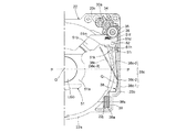
図15と図16を参照して本発明の第2の実施形態を説明する。図1ないし図12及び図14に示した第1の実施形態では、送りねじ36とAFナット37によって3群レンズ枠51の移動を制御しているが、第2の実施形態では、レンズ群LGを保持するレンズ枠(保持部材)151の駆動機構として、送りねじに代えて、リードカム軸136を用いている。レンズ枠151は、円筒状部151aに形成したガイド穴に対してガイド軸(進退ガイド部材)152を摺動可能に挿通させ、該円筒状部151aと撮影光軸Oを挟んで略対称の位置に形成した回り止め溝151dに対して回り止め軸153を摺動可能に係合させることで、撮影光軸Oと平行な方向へ直進案内されていて、ガイド軸152の案内を受ける円筒状部151aからガイドピン151bを突出させている。ガイドピン151bは、リードカム軸136の周面に形成したリード溝136aに係合している。リード溝136aは、撮影光軸Oに対して傾斜する一対の対向ガイド面を有していて、この一対の対向ガイド面とガイドピン151bの間には、ガイドピン151bの摺動を可能にさせる所定のクリアランスが設けられている。リードカム軸136の一端部にはギヤ135が設けられていて、該ギヤ135を介してモータ130によって回転力を与えると、リードカム軸136は撮影光軸Oと平行な回転中心によって回転駆動される。すると、リード溝136aのガイド面によってガイドピン151bが摺動案内されて、レンズ枠151は光軸方向に移動される。   A second embodiment of the present invention will be described with reference to FIGS. 15 and 16. In the first embodiment shown in FIGS. 1 to 12 and 14, the movement of the third group lens frame 51 is controlled by the feed screw 36 and the AF nut 37, but in the second embodiment, the lens group LG is controlled. As a driving mechanism for the lens frame (holding member) 151 that holds the lead, a lead cam shaft 136 is used instead of the feed screw. The lens frame 151 has a guide shaft (advancing / retracting guide member) 152 slidably inserted into a guide hole formed in the cylindrical portion 151a, and a substantially symmetrical position with the cylindrical portion 151a and the photographing optical axis O interposed therebetween. A cylindrical portion that is guided in a straight line in a direction parallel to the photographic optical axis O and is guided by the guide shaft 152 by slidably engaging the detent shaft 153 with the detent groove 151d formed in A guide pin 151b protrudes from 151a. The guide pin 151 b is engaged with a lead groove 136 a formed on the peripheral surface of the lead cam shaft 136. The lead groove 136a has a pair of opposed guide surfaces that are inclined with respect to the photographing optical axis O, and allows the guide pin 151b to slide between the pair of opposed guide surfaces and the guide pin 151b. A predetermined clearance is provided. A gear 135 is provided at one end of the lead cam shaft 136, and when the rotational force is applied by the motor 130 via the gear 135, the lead cam shaft 136 is rotationally driven by a rotation center parallel to the photographing optical axis O. Then, the guide pin 151b is slidably guided by the guide surface of the lead groove 136a, and the lens frame 151 is moved in the optical axis direction.

トーションばねからなるレンズ枠付勢ばね(付勢手段)138は、撮影光軸Oと直交する方向にコイル部138aの軸線を向け、該コイル部138aが円筒状のばね支持突起122jの外周面に支持されている。ばね支持突起122jの位置は固定である。そして、一方の支持腕部(第2の腕部)138bを固定突起122kに係合させ、他方の付勢腕部(第1の腕部)138cをレンズ枠151のばね掛け突起(突起部)151cに係合させている。この係合状態で、レンズ枠付勢ばね138の付勢腕部138cは、ばね支持突起122jに支持されるコイル部138aの軸線と略一致する揺動中心軸138xを中心(支点)として揺動することが可能であり、レンズ枠151を光軸方向前方(図15の左方)に付勢する。この付勢力によって、リード溝136aの対向する一対のガイド面のうち、光軸方向前方の一方のガイド面に対してガイドピン151bが押し付けられて、リード溝136aとガイドピン151bの間のバックラッシュが除去される。なお、ばね掛け突起151cは、円筒状部151aの長手方向の略中央に設けられているため、レンズ枠付勢ばね138の荷重を受けたとき、ガイド軸152に対して円筒状部151aを傾かせるようなモーメントが発生しにくくなっており、光軸方向へのレンズ枠151の円滑移動が保証される。   A lens frame urging spring (biasing means) 138 formed of a torsion spring directs the axis of the coil portion 138a in a direction orthogonal to the photographing optical axis O, and the coil portion 138a is placed on the outer peripheral surface of the cylindrical spring support protrusion 122j. It is supported. The position of the spring support protrusion 122j is fixed. Then, one support arm portion (second arm portion) 138b is engaged with the fixing protrusion 122k, and the other biasing arm portion (first arm portion) 138c is spring-loaded protrusion (projection portion) of the lens frame 151. 151c is engaged. In this engaged state, the urging arm portion 138c of the lens frame urging spring 138 oscillates about the oscillating central axis 138x that substantially coincides with the axis of the coil portion 138a supported by the spring support protrusion 122j. The lens frame 151 is urged forward in the optical axis direction (leftward in FIG. 15). By this urging force, the guide pin 151b is pressed against one guide surface in the optical axis direction among a pair of guide surfaces opposed to the lead groove 136a, and the backlash between the lead groove 136a and the guide pin 151b. Is removed. Since the spring hooking protrusion 151c is provided at substantially the center in the longitudinal direction of the cylindrical portion 151a, the cylindrical portion 151a is inclined with respect to the guide shaft 152 when receiving the load of the lens frame biasing spring 138. Such a moment is hardly generated, and the smooth movement of the lens frame 151 in the optical axis direction is guaranteed.

レンズ枠付勢ばね138によると、モータ130とリードカム軸136を介してレンズ枠151が光軸方向に進退移動されたときに、先の実施形態の3群レンズ付勢ばね38と同様に、着力状態でのばね荷重の変動を小さくすることができ、モータ130の負担を軽減させることができる。また、自由状態から着力状態にするとき、付勢腕部138cの回転量を変化させても、レンズ枠付勢ばね138自体の設置スペースが増大せずスペース効率にも優れている点も、3群レンズ付勢ばね38と同様である。そして、この第2の実施形態から分かるように、本発明における光学要素保持部材への付勢手段の用途は、第1の実施形態のように進退部材の駆動に直接携わるものに限定されず、レンズ枠付勢ばね138のようなバックラッシュ取りのためのものであってもよい。なお、レンズ枠151のような保持部材に対する駆動機構としては、本実施形態におけるリード溝136とガイドピン151bのような溝と突起に限らず、例えばフェイスカム(端面カム)のような構造であってもよい。要は、ガイド面とそれに摺接するフォロアとの間でのバックラッシュ取りが要求されるタイプの駆動機構であれば、本発明は広く適用が可能である。   According to the lens frame biasing spring 138, when the lens frame 151 is moved back and forth in the optical axis direction via the motor 130 and the lead cam shaft 136, the applied force is the same as that of the third group lens biasing spring 38 of the previous embodiment. The fluctuation of the spring load in the state can be reduced, and the load on the motor 130 can be reduced. Further, when changing from the free state to the applied state, even if the rotation amount of the urging arm 138c is changed, the installation space for the lens frame urging spring 138 itself does not increase, and the space efficiency is also excellent. This is the same as the group lens biasing spring 38. As can be seen from the second embodiment, the application of the urging means to the optical element holding member in the present invention is not limited to the one directly involved in driving the advance / retreat member as in the first embodiment, The lens frame biasing spring 138 may be used for backlash removal. The driving mechanism for the holding member such as the lens frame 151 is not limited to the groove and the projection such as the lead groove 136 and the guide pin 151b in the present embodiment, but has a structure such as a face cam (end face cam). May be. In short, the present invention can be widely applied to any drive mechanism that requires backlash removal between the guide surface and the follower that is in sliding contact with the guide surface.

第1と第2の実施形態では、3群レンズ枠51とレンズ枠151に対する付勢手段はそれぞれ、単体のトーションばねからなる3群レンズ付勢ばね38とレンズ枠付勢ばね138となっている。しかし、付勢手段は、保持部材が保持する光学要素を通る光軸の方向に揺動する揺動着力部を介して該保持部材に付勢力を付与するという要件を満たしていれば、こうした単体のトーションばねに限定されるものではない。続いて、図17以下を参照して、付勢手段の態様を異ならせた第3ないし第5の実施形態を説明する。なお以下の各実施形態は、付勢手段とそれに関する構成以外は第1の実施形態と共通しており、第1の実施形態と共通する要素については同符号、同部材名で表す。   In the first and second embodiments, the urging means for the third group lens frame 51 and the lens frame 151 are a third group lens urging spring 38 and a lens frame urging spring 138, each of which is a single torsion spring. . However, if the urging means satisfies such a requirement that the urging force is applied to the holding member via a swinging force applying portion that oscillates in the direction of the optical axis passing through the optical element held by the holding member, such a single unit is sufficient. It is not limited to the torsion spring. Next, with reference to FIG. 17 and the following, third to fifth embodiments in which the mode of the urging means is different will be described. Each of the following embodiments is common to the first embodiment except for the biasing means and the configuration related thereto, and the elements common to the first embodiment are denoted by the same reference numerals and the same member names.

図17ないし図19に示す第3の実施形態では、3群レンズ枠51に対する付勢手段を、揺動レバー(付勢手段、レバー部材)70とトーションばね238で構成している。揺動レバー70は、その一端部が、固定鏡筒22に設けた揺動支持突起22mに対して回動自在に支持されていて、該揺動支持突起22mの軸線に略一致する揺動中心軸70xを中心(支点)として撮影光軸Oと平行な平面内で揺動することができる。揺動レバー70の他端部は、3群レンズ枠51に設けたレバー係合突起51jに係合している。揺動支持突起22mの外周面にはさらに、トーションばね238のコイル部238aが嵌合支持されている。トーションばね238は、コイル部238aから外径方向に延出された支持腕部238bを固定鏡筒22の固定突起22nに係合させ、付勢腕部238cを揺動レバー70の軸支部近傍に係合させていて、該揺動レバー70を図19の時計方向に回動付勢している。この揺動レバー70に対する付勢力は、レバー係合突起51jを介して3群レンズ枠51を光軸方向前方に押圧するように作用する。   In the third embodiment shown in FIGS. 17 to 19, the biasing means for the third group lens frame 51 is constituted by a swing lever (biasing means, lever member) 70 and a torsion spring 238. One end of the swing lever 70 is rotatably supported with respect to the swing support protrusion 22m provided on the fixed barrel 22, and the swing center substantially coincides with the axis of the swing support protrusion 22m. It can swing in a plane parallel to the photographing optical axis O with the axis 70x as the center (fulcrum). The other end portion of the swing lever 70 is engaged with a lever engagement protrusion 51j provided on the third group lens frame 51. A coil portion 238a of a torsion spring 238 is further fitted and supported on the outer peripheral surface of the swing support protrusion 22m. The torsion spring 238 engages the support arm portion 238b extending from the coil portion 238a in the outer diameter direction with the fixed protrusion 22n of the fixed barrel 22, and the biasing arm portion 238c near the shaft support portion of the swing lever 70. The rocking lever 70 is urged to rotate clockwise in FIG. The urging force with respect to the swing lever 70 acts to press the third group lens frame 51 forward in the optical axis direction via the lever engaging projection 51j.

揺動レバー70は、それ自体は揺動方向への弾性を有するものではないが、トーションばね238によって付勢力を与えられることにより、該トーションばね238の付勢腕部238cと揺動レバー70とが、事実上、第1及び第2の実施形態における付勢ばね38、138の付勢腕部38c、138cと同様の揺動着力部として機能される。そのため、先の実施形態における付勢手段と同じく、省スペースに配置可能でありながら、3群レンズ枠51に対しての着力状態での荷重変動を抑えてAFモータ30の負荷を軽減できる。なお、この実施形態と異なり、トーションばね238のコイル部138aを、揺動レバー70の揺動支持突起22mとは別の支持部によって支持させる態様にすることも可能である。   The swing lever 70 itself does not have elasticity in the swing direction. However, when the biasing force is applied by the torsion spring 238, the swing arm 238c of the torsion spring 238, the swing lever 70, However, in practice, it functions as a swinging force applying portion similar to the urging arm portions 38c and 138c of the urging springs 38 and 138 in the first and second embodiments. Therefore, like the urging means in the previous embodiment, the load on the AF motor 30 can be reduced by suppressing the load fluctuation in the applied state with respect to the third group lens frame 51 while being able to be arranged in a space-saving manner. Unlike this embodiment, the coil portion 138a of the torsion spring 238 can be supported by a support portion different from the swing support protrusion 22m of the swing lever 70.

図20に示す第4の実施形態は、第3の実施形態で採用した揺動レバー70に対する付勢部材として、トーションばね238を引張ばね338に置き換えたものである。揺動レバー70は、揺動支持突起22mによる軸支部分から3群レンズ枠51のレバー係合突起51jとの係合方向に延設されたメインアーム70aに加えて、該メインアーム70aと略反対方向に延出されたばね掛けアーム70bを有している。引張ばね338は、このばね掛けアーム70bに一端部を係合させ、他端部を固定鏡筒22に形成したばね掛け突起22pに係合させ、その軸線方向が概ね撮影光軸Oと平行になるように配置されている。揺動レバー70において、揺動支持突起22mの中心からレバー係合突起51jとの係合部E1までのメインアーム70aの長さD1と、揺動支持突起22mの中心から引張ばね338との係合部E2までのばね掛けアーム70bの長さD2は、D1>D2の関係にある。このメインアーム70aとばね掛けアーム70bの長さの比率(レバー比)によって、3群レンズ枠51の光軸方向の単位移動量あたりの、メインアーム70a側の係合部E1の移動量(揺動支持突起22mを中心とする回転方向移動量)と、ばね掛けアーム70b側の係合部E2の移動量(同)は、後者の方が小さくなる。その結果、図13と図20の比較から分かるように、3群レンズ枠51に対する着力状態での引張ばね338の最小長さLminと最大長さLmaxの間の変位量Lv3が小さくなり、付勢手段として単独の引張ばねを用いた場合よりも荷重の変動を抑えることができ、最大荷重を小さくしてAFモータ30の負担を軽減することが可能となっている。   In the fourth embodiment shown in FIG. 20, the torsion spring 238 is replaced with a tension spring 338 as an urging member for the swing lever 70 employed in the third embodiment. The swing lever 70 is substantially opposite to the main arm 70a in addition to the main arm 70a extending from the shaft support portion by the swing support protrusion 22m in the engaging direction with the lever engaging protrusion 51j of the third group lens frame 51. It has a spring arm 70b extending in the direction. The tension spring 338 has one end engaged with the spring arm 70b and the other end engaged with a spring protrusion 22p formed on the fixed barrel 22, and its axial direction is substantially parallel to the photographing optical axis O. It is arranged to be. In the swing lever 70, the length D1 of the main arm 70a from the center of the swing support protrusion 22m to the engaging portion E1 with the lever engagement protrusion 51j and the tension spring 338 from the center of the swing support protrusion 22m. The length D2 of the spring hanging arm 70b up to the joint E2 is in a relationship of D1> D2. Depending on the ratio of the lengths of the main arm 70a and the spring hook arm 70b (lever ratio), the amount of movement (fluctuation) of the engaging portion E1 on the main arm 70a side per unit movement amount of the third group lens frame 51 in the optical axis direction. The latter is smaller in the amount of movement in the rotational direction around the moving support protrusion 22m) and the amount of movement (same) of the engaging portion E2 on the spring hook arm 70b side. As a result, as can be seen from the comparison between FIG. 13 and FIG. 20, the displacement Lv3 between the minimum length Lmin and the maximum length Lmax of the tension spring 338 in the applied state with respect to the third group lens frame 51 is reduced, and the bias is applied. The variation of the load can be suppressed as compared with the case where a single tension spring is used as the means, and the load on the AF motor 30 can be reduced by reducing the maximum load.

図21の第5の実施形態は、第4の実施形態の引張ばね338を、引張方向が異なる引張ばね438に置き換えたものである。揺動レバー70は、揺動支持突起22mによる軸支部分から、メインアーム70aとは略直交する回転方向位相でばね掛けアーム70cを突出させている。引張ばね438は、このばね掛けアーム70cに一端部を係合させ、他端部を固定鏡筒22に形成したばね掛け突起22qに係合させ、その軸線方向が概ね撮影光軸Oと直交する鏡筒上下方向を向くように配置されている。揺動レバー70において、揺動支持突起22mの中心からレバー係合突起51jとの係合部E1までのメインアーム70aの長さD1と、揺動支持突起22mの中心から引張ばね438との係合部E3までのばね掛けアーム70cの長さD3は、D1>D3の関係にある。よって、3群レンズ枠
51が光軸方向に進退したときには、メインアーム70a側の係合部E1の移動量(揺動支持突起22mを中心とする回転方向移動量)よりも、ばね掛けアーム70c側の係合部E3の移動量(同)の方が小さくなる。その結果、3群レンズ枠51に対する着力状態での引張ばね438の最小長さLminと最大長さLmaxの間の変位量Lv4が小さくなり、付勢手段として単独の引張ばねを用いた場合よりも荷重の変動を抑えることができ、最大荷重を小さくしてAFモータ30の負担を軽減できる。
The fifth embodiment in FIG. 21 is obtained by replacing the tension spring 338 of the fourth embodiment with a tension spring 438 having a different tension direction. The swing lever 70 protrudes the spring hook arm 70c from the shaft support portion by the swing support protrusion 22m with a rotational direction phase substantially orthogonal to the main arm 70a. The tension spring 438 has one end engaged with the spring arm 70 c and the other end engaged with a spring protrusion 22 q formed on the fixed barrel 22, and its axial direction is substantially perpendicular to the photographing optical axis O. It arrange | positions so that the lens-barrel may face the up-down direction. In the swing lever 70, the length D1 of the main arm 70a from the center of the swing support protrusion 22m to the engagement portion E1 with the lever engagement protrusion 51j and the tension spring 438 from the center of the swing support protrusion 22m. The length D3 of the spring hook arm 70c up to the joint E3 is in a relationship of D1> D3. Therefore, when the third group lens frame 51 moves back and forth in the optical axis direction, the spring hooking arm 70c is larger than the moving amount of the engaging portion E1 on the main arm 70a side (moving amount in the rotational direction around the swinging support protrusion 22m). The amount of movement (same) of the side engaging portion E3 is smaller. As a result, the amount of displacement Lv4 between the minimum length Lmin and the maximum length Lmax of the tension spring 438 in the applied state with respect to the third group lens frame 51 becomes smaller, than when a single tension spring is used as the biasing means. The fluctuation of the load can be suppressed, and the load on the AF motor 30 can be reduced by reducing the maximum load.

第4、第5の実施形態では、揺動レバー70におけるメインアーム70aの長さ(D1)と、ばね掛けアーム70b、70cの長さ(D2、D3)の比は、D2<D1/2、もしくはD3<D1/2を満たすことが好ましい。   In the fourth and fifth embodiments, the ratio of the length (D1) of the main arm 70a in the swing lever 70 to the lengths (D2, D3) of the spring hanging arms 70b and 70c is D2 <D1 / 2, Alternatively, it is preferable that D3 <D1 / 2 is satisfied.

第4、第5の実施形態から分かるように、3群レンズ枠51の付勢手段として揺動レバー70を介在させることにより、トーションばねのみならず、軸線方向に伸縮するタイプのばねにおいても荷重の変動を抑えることができる。この観点から、第4、第5の実施形態のような引張ばね338、438に変えて、圧縮ばねと揺動レバーの組み合わせで付勢手段を構成しても同様の効果が得られる。   As can be seen from the fourth and fifth embodiments, the load is applied not only to the torsion spring but also to the type of spring that expands and contracts in the axial direction by interposing the swing lever 70 as the biasing means of the third group lens frame 51. Fluctuations can be suppressed. From this point of view, the same effect can be obtained even if the urging means is constituted by a combination of a compression spring and a swing lever instead of the tension springs 338 and 438 as in the fourth and fifth embodiments.

以上の各実施形態においてはさらに、撮影光軸Oに沿う方向へ3群レンズ枠51やレンズ枠151を移動付勢する付勢手段が、該移動方向と直交する方向への荷重も与えるようになっており、これにより、3群レンズ枠51やレンズ枠151の進退ガイド機構におけるバックラッシュ取りが行われている。   In each of the above embodiments, the urging means for moving and urging the third group lens frame 51 and the lens frame 151 in the direction along the photographing optical axis O also applies a load in the direction orthogonal to the moving direction. Accordingly, backlash removal is performed in the advance / retreat guide mechanism of the third group lens frame 51 and the lens frame 151.

第1の実施形態における3群レンズ付勢ばね38の付勢腕部38cは、3群レンズ枠51のばね掛け突起51hに係合された着力状態では、図10及び図11に実線で示す、揺動中心軸38xと直交する揺動平面(揺動面)に沿って延びていて、前述の通り、3群レンズ枠51が撮影光軸Oに沿って移動するときに該揺動平面内で揺動される。この付勢腕部38cは、3群レンズ枠51のばね掛け突起51hに係合しない自由状態では、図10及び図11に二点鎖線で示すように、揺動平面と非平行をなし(揺動面外に位置し)、撮影光軸Oに接近する方向に傾いた倒れ形状になっている。そして、付勢腕部38cをばね掛け突起51hに係合させる着力状態にする際、揺動平面に接近するように、該付勢腕部38cを図10及び図11中の反時計方向へ弾性変形させ、3群レンズ枠51に形成した立壁部(当接部)51kに当接させて自由状態への復帰を規制する。立壁部51kは、付勢腕部38cの揺動平面と略平行をなす平面状をなし、その一側面に該付勢腕部38cに当接する半円状断面部51mが形成されていて、この半円状断面部51mの前方に、前述のばね掛け突起51hが突設されている。   The urging arm portion 38c of the third group lens urging spring 38 in the first embodiment is indicated by a solid line in FIGS. 10 and 11 in an applied state in which the urging arm portion 38c is engaged with the spring hooking protrusion 51h of the third group lens frame 51. It extends along a swinging plane (swinging surface) orthogonal to the swinging center axis 38x, and when the third lens group frame 51 moves along the photographing optical axis O as described above, It is swung. In a free state where the urging arm portion 38c is not engaged with the spring hooking projection 51h of the third group lens frame 51, the urging arm portion 38c is not parallel to the oscillating plane (as shown by a two-dot chain line in FIGS. 10 and 11). It is located outside the moving surface) and has a tilted shape inclined in a direction approaching the photographing optical axis O. When the biasing arm portion 38c is brought into an applied state to engage with the spring hooking protrusion 51h, the biasing arm portion 38c is elastically counterclockwise in FIGS. 10 and 11 so as to approach the swinging plane. It is deformed and brought into contact with a standing wall portion (contact portion) 51k formed in the third group lens frame 51 to restrict the return to the free state. The standing wall portion 51k has a planar shape that is substantially parallel to the swinging plane of the urging arm portion 38c, and a semicircular cross-sectional portion 51m that abuts against the urging arm portion 38c is formed on one side surface thereof. The aforementioned spring-hanging projection 51h is provided in front of the semicircular cross-section 51m.

付勢腕部38cを自由状態から弾性変形させて立壁部51k(半円状断面部51m)に当接させると、その撓み変形から復帰しようとする力によって、3群レンズ枠51の立壁部51kが同図中の右方に向けて押圧される。立壁部51kは、3群レンズ枠51のガイド腕部51bの先端部におけるガイド穴51dの直下の位置に設けられており、該立壁部51kに対して付勢腕部38cから入力される荷重は、ガイド穴51dを図10及び図11の右方向に変位させようとする押圧力として作用する。その結果、ガイド穴51dの内壁が3群ガイド軸52に押し付けられ、ガイド穴51dと3群ガイド軸52の関係において、3群レンズ枠51の移動方向(撮影光軸Oに沿う方向)と直交する方向での遊びが除去される。また、撮影光軸Oを挟んでガイド穴51d及び3群ガイド軸52と対称の位置関係にある回転規制突起51eと直進ガイド溝22fの側にもモーメントが作用して、直進ガイド溝22fの一対の対向ガイド面の一方に回転規制突起51eが押し付けられて遊びが除去される。よって、3群レンズ枠51が、進退ガイド機構のクリアランスを起因とする位置変動を生じることなく安定して保持される。この付勢腕部38cから立壁部51kへの付勢力は、3群レンズ付勢ばね38が着力状態にある間は常に付与されるので、3群レンズ枠51をいずれの位置に移動させても安定保持が維持される。これにより、ガタつきや異音を生じさせずに3群レンズ枠51をスムーズに移動させることが可能となる。また3群レンズ枠51を停止させた状態での、撮影光軸Oと直交する平面内での該3群レンズ枠51の位置精度が向上する。なお、3群レンズ枠51の立壁部51kや半円状断面部51mは、ばね掛け突起51hに対して付勢腕部38cを係合させたときに、他の部位に付勢腕部38cが接触するのを防ぐ保護機能も有する。   When the urging arm portion 38c is elastically deformed from the free state and brought into contact with the standing wall portion 51k (semicircular cross-section portion 51m), the standing wall portion 51k of the third group lens frame 51 is caused by the force to return from the bending deformation. Is pushed toward the right in the figure. The standing wall portion 51k is provided at a position immediately below the guide hole 51d at the tip of the guide arm portion 51b of the third group lens frame 51, and the load input from the urging arm portion 38c to the standing wall portion 51k is as follows. The guide hole 51d acts as a pressing force to displace the guide hole 51d in the right direction in FIGS. As a result, the inner wall of the guide hole 51d is pressed against the third group guide shaft 52, and the relationship between the guide hole 51d and the third group guide shaft 52 is orthogonal to the moving direction of the third group lens frame 51 (the direction along the photographing optical axis O). Play in the direction to do is eliminated. A moment also acts on the rotation restricting projection 51e and the rectilinear guide groove 22f that are symmetrical with the guide hole 51d and the third group guide shaft 52 across the photographing optical axis O, and a pair of rectilinear guide grooves 22f. The rotation restricting projection 51e is pressed against one of the opposing guide surfaces to remove play. Therefore, the third group lens frame 51 is stably held without causing a position change due to the clearance of the advance / retreat guide mechanism. Since the urging force from the urging arm portion 38c to the standing wall portion 51k is always applied while the third group lens urging spring 38 is in the applied force state, the third group lens frame 51 can be moved to any position. Stable retention is maintained. Accordingly, it is possible to smoothly move the third group lens frame 51 without causing rattling or abnormal noise. Further, the positional accuracy of the third group lens frame 51 in a plane orthogonal to the photographing optical axis O in a state where the third group lens frame 51 is stopped is improved. The standing wall portion 51k and the semicircular cross-sectional portion 51m of the third group lens frame 51 have the urging arm portion 38c at another portion when the urging arm portion 38c is engaged with the spring hooking projection 51h. It also has a protective function to prevent contact.

以上のように、立壁部51kに対して3群レンズ枠51の移動方向と直交する方向への付勢力を与える付勢手段は、該3群レンズ枠51を撮影光軸Oに沿う方向に付勢する3群レンズ付勢ばね38(付勢腕部38c)と同一なので、独立した付勢部材を設けることなく、部品点数が少ない簡単かつ省スペースな構成で、3群レンズ枠51と、その進退ガイドを担う3群ガイド軸52や直進ガイド溝22fとの間のバックラッシュ取りを行うことができる。   As described above, the urging means for applying the urging force in the direction perpendicular to the moving direction of the third group lens frame 51 to the standing wall 51k applies the third group lens frame 51 in the direction along the photographing optical axis O. Since it is the same as the third group lens urging spring 38 (the urging arm portion 38c) to be urged, the third group lens frame 51 and its Backlash removal can be performed between the third group guide shaft 52 and the straight guide groove 22f that carry the advance / retreat guide.

第1の実施形態の3群レンズ付勢ばね38の付勢腕部38cと同様に、第2の実施形態におけるレンズ枠付勢ばね138の付勢腕部138cも、レンズ枠151のばね掛け突起151cに係合されない自由状態では、図16に二点鎖線で示すように、同図に実線で示す着力状態での揺動平面上の位置に対して、撮影光軸Oに接近する方向に傾いた形状をなしている。そして、付勢腕部138cをばね掛け突起151cに係合する着力状態にする際に、図16の時計方向に弾性変形され、その復元方向の力によって、レンズ枠151の円筒状部151aの外面部(当接部)を図16中の左方向に押圧する。この押圧力によって、ガイド軸152に対するレンズ枠151のガタつきが防止され、撮影光軸Oと直交する平面内におけるレンズ群LGの位置が安定する。すなわち、レンズ枠付勢ばね138は、レンズ枠151をその移動方向に付勢する機能と、該レンズ枠151を移動方向との直交方向に付勢する機能とを兼ね備えていて、部品点数の少ない簡単かつ省スペースな構成でレンズ枠151を安定保持させることができる。   Similar to the urging arm portion 38c of the third group lens urging spring 38 of the first embodiment, the urging arm portion 138c of the lens frame urging spring 138 in the second embodiment is also a spring hooking projection of the lens frame 151. In a free state in which it is not engaged with 151c, as shown by a two-dot chain line in FIG. 16, it tilts in a direction approaching the photographing optical axis O with respect to a position on the swing plane in the applied force state indicated by a solid line in FIG. It has a different shape. Then, when the biasing arm portion 138c is brought into an applied state to be engaged with the spring hooking protrusion 151c, the outer surface of the cylindrical portion 151a of the lens frame 151 is elastically deformed in the clockwise direction in FIG. The portion (contact portion) is pressed in the left direction in FIG. This pressing force prevents the lens frame 151 from rattling with respect to the guide shaft 152 and stabilizes the position of the lens group LG in a plane orthogonal to the photographing optical axis O. That is, the lens frame urging spring 138 has both a function of urging the lens frame 151 in its moving direction and a function of urging the lens frame 151 in a direction orthogonal to the moving direction, and has a small number of parts. The lens frame 151 can be stably held with a simple and space-saving configuration.

第3ないし第5の実施形態の揺動レバー70も、3群レンズ枠51に対してその移動方向と直交する方向への荷重を与えるようになっている。第3の実施形態で代表して説明すると、揺動レバー70は、撮影光軸Oと直交する方向へ弾性変形可能となっており、3群レンズ枠51のばね掛け突起51hに係合しない自由状態では、図17及び図18に二点鎖線で示すように、同図に実線で示す着力状態での揺動平面上の位置に対して、撮影光軸Oに接近する方向に傾いた倒れ形状になっている。そして、揺動レバー70は、ばね掛け突起51hに係合する着力状態にされるとき、図17及び図18中の反時計方向へ弾性変形されて3群レンズ枠51の立壁部51k(半円状断面部51m)に当接され、その撓み変形を解放しようとする力によって立壁部51kを同図中の右方に向けて押圧する。この押圧力により、3群ガイド軸52や直進ガイド溝22fに対する3群レンズ枠51のガタつきが防止され、撮影光軸Oと直交する平面内における第3レンズ群LG3の位置が安定する。すなわち、揺動レバー70は、トーションばね238の付勢力を受けて3群レンズ枠51をその移動方向に付勢する機能と、該揺動レバー70自身の弾性変形によって3群レンズ枠51を移動方向との直交方向に付勢する機能とを兼ね備えていて、部品点数が少ない簡単かつ省スペースな構成で3群レンズ枠51を安定保持させることができる。詳細な説明は省略するが、第4、第5の実施形態における揺動レバー70も同様に、異なる2つの方向に3群レンズ枠51を付勢する複合的な機能を有している。   The swing lever 70 of the third to fifth embodiments is also configured to apply a load to the third group lens frame 51 in a direction orthogonal to its moving direction. As described in the third embodiment, the swing lever 70 can be elastically deformed in a direction orthogonal to the photographing optical axis O, and is free to engage with the spring projection 51h of the third group lens frame 51. In the state, as shown by a two-dot chain line in FIGS. 17 and 18, a tilted shape tilted in a direction approaching the photographing optical axis O with respect to the position on the swing plane in the applied force state shown by the solid line in FIG. It has become. The swing lever 70 is elastically deformed counterclockwise in FIG. 17 and FIG. 18 when it is in an applied force state to engage with the spring hooking protrusion 51h, and the standing wall portion 51k (semicircle) of the third group lens frame 51. The standing wall 51k is pressed toward the right in the figure by a force which is brought into contact with the section 51m) and tries to release its deformation. This pressing force prevents the third group lens frame 51 from rattling with respect to the third group guide shaft 52 and the rectilinear guide groove 22f, and stabilizes the position of the third lens group LG3 in a plane orthogonal to the photographing optical axis O. In other words, the swing lever 70 receives the biasing force of the torsion spring 238 and moves the third group lens frame 51 by the function of biasing the third group lens frame 51 in its moving direction and the elastic deformation of the swing lever 70 itself. The third group lens frame 51 can be stably held with a simple and space-saving configuration with a small number of parts. Although a detailed description is omitted, the swing lever 70 in the fourth and fifth embodiments similarly has a complex function of urging the third group lens frame 51 in two different directions.

図22ないし図26は、光学要素の保持部材に対しその移動方向と直交する方向の付勢力を与えるに際して、より効果的な変形例を示している。この変形例は、先に説明した第1の実施形態の一部構成を異ならせたものであり、既述部分と共通する箇所については説明を省略する。   22 to 26 show modified examples that are more effective in applying an urging force in a direction orthogonal to the moving direction to the holding member of the optical element. In this modification, a part of the configuration of the first embodiment described above is made different, and description of portions common to the above-described portions is omitted.

図22と図23は第1の変形例を示している。鏡筒後面板23は、CCD24を保持し固定鏡筒22の筒状ハウジング部(押圧手段、固定壁部材、内側壁部材、内側筒状部材)22aの後面を塞ぐ本体部23aと、該本体部23aから光軸方向前方に延出された保護壁部(押圧手段、固定壁部材、外側壁部材)23bを有している。保護壁部23bは筒状ハウジング部22aの外周面に対向し、その間に収納空間Qを形成している。収納空間Q内には3群レンズ付勢ばね38が保持されている。既述の通り、3群レンズ付勢ばね38の付勢腕部38cは、自由状態では図23に二点鎖線で示すように、撮影光軸Oに接近する方向に傾いた倒れ形状になっており、3群レンズ枠51のばね掛け突起51hに係合させた着力状態で、図23の実線のように弾性変形される。この着力状態において、付勢腕部38cに当接するばね押圧部(突出押圧部)23cが、鏡筒後面板23の保護壁部23bに形成されている。図22に示すように、ばね押圧部23cは、保護壁部23bのうち収納空間Qに臨む側(すなわち筒状ハウジング部22aの外周面に対向する側)の面に突出形成された、光軸方向に長いリブ状の突起であり、3群レンズ枠51が光軸方向の可動範囲のいずれの位置にあるときも、付勢腕部38cとの当接を維持する。   22 and 23 show a first modification. The lens barrel rear surface plate 23 holds a CCD 24 and closes the rear surface of the cylindrical housing portion (pressing means, fixed wall member, inner wall member, inner cylindrical member) 22a of the fixed lens barrel 22, and the main body portion. It has a protective wall part (pressing means, fixed wall member, outer wall member) 23b extending forward from the optical axis direction 23a. The protective wall portion 23b faces the outer peripheral surface of the cylindrical housing portion 22a and forms a storage space Q therebetween. A third group lens biasing spring 38 is held in the storage space Q. As described above, the urging arm portion 38c of the third group lens urging spring 38 is in a tilted shape inclined in a direction approaching the photographing optical axis O as shown by a two-dot chain line in FIG. In the state of the applied force engaged with the spring hooking protrusion 51h of the third lens group frame 51, it is elastically deformed as indicated by the solid line in FIG. In this applied state, a spring pressing portion (projecting pressing portion) 23c that contacts the urging arm portion 38c is formed on the protective wall portion 23b of the lens barrel rear surface plate 23. As shown in FIG. 22, the spring pressing portion 23 c protrudes from the surface of the protective wall portion 23 b that faces the storage space Q (that is, the side facing the outer peripheral surface of the cylindrical housing portion 22 a). This is a rib-shaped projection that is long in the direction, and maintains contact with the urging arm portion 38c when the third lens group frame 51 is in any position within the movable range in the optical axis direction.

ばね押圧部23cは、付勢腕部38cをばね掛け突起51hに係合させたとき、立壁部51k(半円状断面部51m)側への押圧力を与えるように、その突出量が設定されている。そのため、3群レンズ付勢ばね38において、3群レンズ枠51の移動方向と直交する方向への付勢力を確実に作用させることができ、3群レンズ枠51の進退ガイド部である3群ガイド軸52とガイド穴51dの間のガタを良好に除去することができる。   The amount of protrusion of the spring pressing portion 23c is set so as to give a pressing force toward the standing wall portion 51k (semicircular cross-section 51m) when the urging arm portion 38c is engaged with the spring hooking projection 51h. ing. Therefore, the third group lens biasing spring 38 can reliably apply a biasing force in a direction orthogonal to the moving direction of the third group lens frame 51, and the third group guide which is an advance / retreat guide portion of the third group lens frame 51. The play between the shaft 52 and the guide hole 51d can be removed satisfactorily.

図24は第2の変形例を示している。同図に実線で示す着力状態にある3群レンズ付勢ばね38の付勢腕部38cに対して、鏡筒後面板23の保護壁部23bに設けたばね押圧部23cによる押圧力を加えている点では、第1の変形例と共通している。この変形例では、ハウジング22の筒状ハウジング部22a′が、完全な筒体ではなく、保護壁部23bに対向する部分が欠損した不完全筒体であるところが相違する。これに伴い、3群レンズ付勢ばね38のコイル部38aは、筒状ハウジング部22a′側ではなく、保護壁部23b側に設けたばね支持突起23d上に、ばね留めねじ39′によって保持されている。このように、本発明において付勢手段の内側に位置する筒状部材(筒状ハウジング部22a′)は、完全な筒状でなくてもよく、その場合は、その外側の外側壁部材(保護壁部23b)に、付勢手段(3群レンズ付勢ばね38)に対する押圧箇所を設けることが有効である。   FIG. 24 shows a second modification. The pressing force by the spring pressing portion 23c provided on the protective wall portion 23b of the lens barrel rear surface plate 23 is applied to the urging arm portion 38c of the third group lens urging spring 38 in the applied state shown by the solid line in FIG. This is common to the first modification. This modification is different in that the cylindrical housing portion 22a ′ of the housing 22 is not a complete cylindrical body but an incomplete cylindrical body in which a portion facing the protective wall portion 23b is missing. Accordingly, the coil portion 38a of the third group lens urging spring 38 is held by the spring retaining screw 39 'on the spring support protrusion 23d provided on the protective wall portion 23b side, not on the cylindrical housing portion 22a' side. Yes. Thus, in this invention, the cylindrical member (cylindrical housing part 22a ') located inside an urging | biasing means does not need to be perfect cylinder shape, In that case, the outer side wall member (protection) in the outer side It is effective to provide a pressing portion for the urging means (the third group lens urging spring 38) on the wall 23b).

図25は第3の変形例を示している。この変形例は、3群レンズ付勢ばね38の付勢腕部38cを鏡筒後面板23の保護壁部23bに当て付けて、3群レンズ枠51の移動方向と直交する方向への付勢力を確実に作用させる点では先の第1及び第2の変形例と共通しているが、付勢腕部38c側の形状によってそれを達成しているところが異なる。すなわち、付勢腕部38cは、コイル部38aから保護壁部23bに接近する方向(筒状ハウジング部22aから離れる方向)に延びる外方延出部38c-1と、該外方延出部38c-1に続く屈曲部38c-2と、該屈曲部38c-2から筒状ハウジング部22aに接近する方向(保護壁部23bから離れる方向)に延びる内方延出部38c-3を有する、保護壁部23b側に向けて凸とされた屈曲形状をなしている。そして、図25に二点鎖線で示す自由状態から実線で示す着力状態に付勢腕部38cを弾性変形させると、屈曲部38c-2が保護壁部23bに当接して押し付けられる。そして、この押し付けに対する反力によって、第1及び第2の変形例の場合と同様に、付勢腕部38cの内方延出部38c-3が立壁部51k(半円状断面部51m)側に向けて押し込まれる。   FIG. 25 shows a third modification. In this modification, the urging force in the direction orthogonal to the moving direction of the third lens group frame 51 is applied by applying the urging arm portion 38c of the third lens group urging spring 38 to the protective wall 23b of the lens barrel rear plate 23. Is the same as the first and second modified examples described above, but is different depending on the shape of the urging arm portion 38c. That is, the urging arm portion 38c includes an outward extending portion 38c-1 extending in a direction approaching the protective wall portion 23b from the coil portion 38a (a direction away from the cylindrical housing portion 22a), and the outward extending portion 38c. -1 and a bent portion 38c-2, and an inwardly extending portion 38c-3 extending from the bent portion 38c-2 in a direction approaching the cylindrical housing portion 22a (a direction away from the protective wall portion 23b). It has a bent shape that is convex toward the wall 23b. Then, when the urging arm portion 38c is elastically deformed from the free state indicated by the two-dot chain line in FIG. 25 to the applied state indicated by the solid line, the bent portion 38c-2 is pressed against the protective wall portion 23b. Then, due to the reaction force against the pressing, the inwardly extending portion 38c-3 of the urging arm portion 38c becomes the standing wall portion 51k (semicircular cross-sectional portion 51m) side, as in the case of the first and second modifications. It is pushed toward.

図26に示す第4の変形例では、第1から第3の変形例とは逆に、鏡筒後面板23の保護壁部23bではなく、固定鏡筒22の筒状ハウジング部22a側に、3群レンズ付勢ばね38の付勢腕部38cに対する押圧箇所を設けている。この変形例では、3群レンズ枠51の進退ガイド部(3群ガイド軸52とガイド穴51d)に対する付勢腕部38cの付勢方向が図23ないし図25とは逆になっており、図26に二点鎖線で示す自由状態から、実線で示すばね掛け突起51hへの着力状態へと付勢腕部38cを弾性変形させたとき、付勢腕部38cは、撮影光軸Oに近い側から離れる側に向けて、ばね掛け突起51hの端部に設けた立壁部51k′(半円状断面部51m′)を押圧する。筒状ハウジング部22aの外周面上には、収納空間Q内(保護壁部23bへの接近方向)へ突出するばね押圧部(突出押圧部)22rが形成されており、このばね押圧部22rが、着力状態の保護壁部23bを、立壁部51k′(半円状断面部51m′)への接近方向に押圧する。よって、この第3の変形例でも、3群レンズ付勢ばね38の付勢腕部38cによって、3群レンズ枠51の移動方向と直交する方向への付勢力を確実に作用させることができる。   In the fourth modified example shown in FIG. 26, contrary to the first to third modified examples, not the protective wall portion 23 b of the lens barrel rear surface plate 23, but the cylindrical housing portion 22 a side of the fixed barrel 22, A pressing portion for the urging arm portion 38c of the third group lens urging spring 38 is provided. In this modification, the urging direction of the urging arm portion 38c with respect to the advance / retreat guide portion (the third group guide shaft 52 and the guide hole 51d) of the third group lens frame 51 is opposite to that shown in FIGS. When the urging arm portion 38c is elastically deformed from the free state indicated by a two-dot chain line in FIG. 26 to the applied state to the spring hooking protrusion 51h indicated by the solid line, the urging arm portion 38c is closer to the photographing optical axis O. The standing wall 51k ′ (semicircular cross-section 51m ′) provided at the end of the spring-hanging projection 51h is pressed toward the side away from the head. On the outer peripheral surface of the cylindrical housing portion 22a, there is formed a spring pressing portion (projecting pressing portion) 22r that protrudes into the storage space Q (the approaching direction to the protective wall portion 23b). Then, the protective wall 23b in the applied state is pressed in the approaching direction to the standing wall 51k ′ (semicircular cross-section 51m ′). Therefore, also in the third modification, the urging force in the direction orthogonal to the moving direction of the third group lens frame 51 can be reliably applied by the urging arm portion 38c of the third group lens urging spring 38.

なお、筒状ハウジング部22aにより付勢腕部38cを押圧する態様では、第3の変形例と同様に、付勢腕部38cに屈曲形状を持たせてもよい。すなわち、図25では、付勢腕部38cが保護壁部23b側に向けて凸とされた屈曲形状であるが、これと逆に、付勢腕部38cを筒状ハウジング部22a側に向けて凸の屈曲形状にして、その屈曲部を筒状ハウジング部22aに当て付けるような態様も可能である。但し、付勢腕部38cの屈曲部を当て付けたときの安定性を確保するため、筒状ハウジング部22aの外周面上には、ばね押圧部22rのような特定の押圧部を設けることが好ましい。   In the aspect in which the urging arm portion 38c is pressed by the cylindrical housing portion 22a, the urging arm portion 38c may have a bent shape as in the third modification. That is, in FIG. 25, the urging arm portion 38c has a bent shape that is convex toward the protective wall portion 23b. On the contrary, the urging arm portion 38c is directed toward the cylindrical housing portion 22a. It is also possible to adopt a mode in which a convex bent shape is formed and the bent portion is applied to the cylindrical housing portion 22a. However, in order to ensure stability when the bent portion of the urging arm portion 38c is applied, a specific pressing portion such as a spring pressing portion 22r may be provided on the outer peripheral surface of the cylindrical housing portion 22a. preferable.

以上の変形例は、第1の実施形態の3群レンズ付勢ばね38の付勢腕部38cに応用したものであるが、第2の実施形態のレンズ枠付勢ばね138の付勢腕部138cや、第3ないし第5の実施形態の揺動レバー70についても同様に適用が可能である。着力状態において、これら付勢腕部138cや揺動レバー70を、進退ガイド部材(3群ガイド軸52、ガイド軸152)による移動方向と直交する方向に押圧することで、進退ガイド部のガタ防止に関してより高い効果が得られる。   The above modification is applied to the urging arm portion 38c of the third group lens urging spring 38 of the first embodiment, but the urging arm portion of the lens frame urging spring 138 of the second embodiment. The same applies to 138c and the swing lever 70 of the third to fifth embodiments. In the applied state, the biasing arm portion 138c and the swing lever 70 are pressed in a direction orthogonal to the moving direction by the advance / retreat guide member (the third group guide shaft 52, the guide shaft 152), thereby preventing backlash of the advance / retreat guide portion. A higher effect can be obtained.

以上、図示実施形態を参照して本発明の実施形態を説明したが、本発明はこの実施形態に限定されるものではない。例えば、図示実施形態では、光軸方向に進退移動される光学要素をフォーカシング用のレンズ群としたが、本発明は、フォーカシング用レンズ群以外の光学要素の位置制御機構としても適用が可能である。   As mentioned above, although embodiment of this invention was described with reference to illustration embodiment, this invention is not limited to this embodiment. For example, in the illustrated embodiment, the optical element moved forward and backward in the optical axis direction is the focusing lens group, but the present invention can also be applied as a position control mechanism for optical elements other than the focusing lens group. .

また、第1の実施形態における3群レンズ付勢ばね38の支持腕部38b、第3の実施形態におけるトーションばね238の支持腕部238b、第4及び第5の実施形態における引張ばね338、438の一端部はそれぞれ、固定鏡筒22に設けた突起部に係合されているが、付勢手段を構成するばねの一端部が係合する対象は、少なくとも3群レンズ枠51に相当する保持部材との間で相対移動を生じるものであれば、固定部材に限らず可動の部材であってもよい。同様に、第3から第5の実施形態におけるレバー部材70を軸支する支持部材も、固定鏡筒22のような固定部材に限定されず、少なくとも3群レンズ枠51に相当する保持部材との間で相対移動を生じるものであればよい。   Further, the support arm portion 38b of the third group lens biasing spring 38 in the first embodiment, the support arm portion 238b of the torsion spring 238 in the third embodiment, and the tension springs 338, 438 in the fourth and fifth embodiments. One end of each is engaged with a protrusion provided on the fixed lens barrel 22, but the object with which one end of the spring constituting the urging means is engaged corresponds to at least the third group lens frame 51. As long as relative movement occurs between the members, the movable member is not limited to a fixed member. Similarly, the support member that pivotally supports the lever member 70 in the third to fifth embodiments is not limited to a fixed member such as the fixed barrel 22, and is at least a holding member corresponding to the third group lens frame 51. Any device that causes relative movement between them may be used.

また、以上の各実施形態では、付勢手段を構成する3群レンズ付勢ばね38の付勢腕部38c、レンズ枠付勢ばね138の付勢腕部138c、揺動レバー70はいずれも直線状をなしており、3群レンズ枠51やレンズ枠151に対する着力状態では、これら付勢腕部38c、138c及び揺動レバー70は、揺動中心軸38x、138x及び70xを中心とした一定の揺動平面内で揺動される。しかし、本発明において、付勢手段の着力部分(揺動部分)はこのような直線状体に限られるものではなく、例えば図25に示した屈曲形状の付勢腕部38cのように、様々な形態をとることが可能である。着力部分が単純な直線状体でない場合、あるいは着力状態においても揺動中心軸との直交方向に対して傾きを有している場合には、その揺動時の軌跡も単純な平面内に収まるものではなくなるが、当該着力部分の特定の部位に着目すれば、揺動中心軸を中心とする一定の面内で移動されるとみなすことができる。本発明においては、この特定部位の移動軌跡が含まれる、揺動中心軸と直交する面を揺動面と定義している。   In each of the above embodiments, the urging arm portion 38c of the third group lens urging spring 38, the urging arm portion 138c of the lens frame urging spring 138, and the swing lever 70, which constitute the urging means, are all linear. In the applied state with respect to the third group lens frame 51 and the lens frame 151, the urging arm portions 38c and 138c and the swing lever 70 are constant around the swing center axes 38x, 138x and 70x. It is swung in the swing plane. However, in the present invention, the urging portion (swinging portion) of the urging means is not limited to such a linear body, and various types such as a bent urging arm portion 38c shown in FIG. It is possible to take various forms. If the applied portion is not a simple linear body or has an inclination with respect to the direction orthogonal to the oscillation center axis even in the applied state, the locus during the oscillation will be within a simple plane. Although it is not a thing, if attention is paid to a specific portion of the applied force portion, it can be considered that the portion is moved within a certain plane centered on the oscillation central axis. In the present invention, a plane perpendicular to the swing central axis that includes the movement locus of the specific part is defined as a swing plane.

本発明の光学要素位置制御機構を適用したズームレンズ鏡筒の収納状態を示す断面図である。It is sectional drawing which shows the accommodation state of the zoom lens barrel to which the optical element position control mechanism of this invention is applied. 同ズームレンズ鏡筒の撮影状態の断面図である。It is sectional drawing of the imaging state of the zoom lens barrel. 同ズームレンズ鏡筒の収納状態の前方斜視図である。It is a front perspective view of the storage state of the zoom lens barrel. 同ズームレンズ鏡筒の収納状態の後方斜視図である。It is a back perspective view of the storage state of the zoom lens barrel. 同ズームレンズ鏡筒の撮影状態の前方斜視図である。It is a front perspective view of the photographing state of the zoom lens barrel. 同ズームレンズ鏡筒の撮影状態で、鏡筒後面板を外した後方斜視図である。It is the back perspective view which removed the barrel back plate in the photography state of the zoom lens barrel. ズームレンズ鏡筒から第3レンズ群の位置制御に関わる部材を取り外した状態の後方斜視図である。It is a back perspective view of the state where a member related to position control of the 3rd lens group was removed from a zoom lens barrel. 3群レンズ枠とその位置制御機構の要部を示す前方斜視図である。It is a front perspective view which shows the principal part of a 3 group lens frame and its position control mechanism. 3群レンズ枠とその位置制御機構の要部を示す後方斜視図である。It is a back perspective view which shows the principal part of a 3 group lens frame and its position control mechanism. 3群レンズ枠とその位置制御機構を主として示した、ズームレンズ鏡筒の正面図である。It is a front view of a zoom lens barrel mainly showing a third group lens frame and its position control mechanism. 図10から3群レンズ枠とその位置制御機構のみを取り出して示した正面図である。It is the front view which took out and showed only the 3 group lens frame and its position control mechanism from FIG. 3群レンズ付勢ばねの作用を示す、3群レンズ枠とその位置制御機構の側面図である。It is a side view of the 3rd group lens frame and its position control mechanism which shows the operation of the 3rd group lens energizing spring. 3群レンズ付勢ばねに引張ばねを用いた比較例における、3群レンズ枠とその位置制御機構の側面図である。It is a side view of a 3 group lens frame and its position control mechanism in a comparative example using a tension spring as a 3 group lens urging spring. 図12の実施形態と図13の比較例によるばね荷重の変動を比較するためのグラフ図であり、(a)は実施形態、(b)は比較例を示す。It is a graph for comparing the fluctuation | variation of the spring load by embodiment of FIG. 12, and the comparative example of FIG. 13, (a) is embodiment, (b) shows a comparative example. 第1の実施形態の送りねじ機構に代えて、リードカム軸を用いた第2の実施形態を示すレンズ群の位置制御機構の側面図である。It is a side view of the position control mechanism of the lens group which shows 2nd Embodiment using a lead cam shaft instead of the feed screw mechanism of 1st Embodiment. 図15の第2の実施形態におけるレンズ群の位置制御機構の正面図である。It is a front view of the position control mechanism of the lens group in 2nd Embodiment of FIG. 3群レンズ枠の付勢手段としてレバー部材とトーションばねを用いた第3の実施形態を示す、3群レンズ枠とその位置制御機構を主としたズームレンズ鏡筒の正面図である。FIG. 10 is a front view of a zoom lens barrel mainly including a third group lens frame and its position control mechanism, showing a third embodiment using a lever member and a torsion spring as a biasing means for the third group lens frame. 図17から3群レンズ枠とその位置制御機構のみを取り出して示した正面図である。It is the front view which took out and showed only the 3 group lens frame and its position control mechanism from FIG. 第3の実施形態におけるレバー部材とトーションばねの作用を示す、3群レンズ枠とその位置制御機構の側面図である。It is a side view of the 3rd group lens frame and its position control mechanism which shows an operation of a lever member and a torsion spring in a 3rd embodiment. 3群レンズ枠の付勢手段としてレバー部材と引張ばねを用いた第4の実施形態を示す、3群レンズ枠とその位置制御機構の側面図である。It is a side view of a 3 group lens frame and its position control mechanism which shows a 4th embodiment using a lever member and a tension spring as urging means of a 3 group lens frame. 3群レンズ枠の付勢手段としてレバー部材と引張ばねを用いた第5の実施形態を示す、3群レンズ枠とその位置制御機構の側面図である。It is a side view of a 3 group lens frame and its position control mechanism which shows a 5th embodiment using a lever member and a tension spring as a biasing means of a 3 group lens frame. 鏡筒後面板の保護壁部に3群レンズ付勢ばねの付勢腕部に対する押圧部を設けた第1の変形例を示す、鏡筒後面板の斜視図である。It is a perspective view of a lens barrel rear plate showing a first modification in which a pressing portion against a biasing arm portion of a third group lens biasing spring is provided on the protective wall portion of the lens barrel rear plate. 第1の変形例において、鏡筒後面板の保護壁部の押圧部によって3群レンズ付勢ばねの付勢腕部を押圧している状態を示す、一部を断面とした背面図である。In a 1st modification, it is the rear view which made the section a part which shows the state which has pressed the urging | biasing arm part of the 3 group lens urging | biasing spring with the press part of the protection wall part of a lens-barrel rear surface plate. 第2の変形例において、鏡筒後面板の保護壁部の押圧部によって3群レンズ付勢ばねの付勢腕部を押圧している状態を示す、一部を断面とした背面図である。In the 2nd modification, it is the rear view which made the section a part which shows the state where the energizing arm part of the 3rd group lens energizing spring is pressed by the press part of the protection wall part of the barrel back plate. 第3の変形例において、3群レンズ付勢ばねの付勢腕部に形成した屈曲部を鏡筒後面板の保護壁部によって押圧している状態を示す、一部を断面とした背面図である。In the 3rd modification, it is a rear view which made the section into a section showing the state where the bent part formed in the energizing arm part of the 3 group lens energizing spring is pressed by the protection wall part of the barrel back plate is there. 第4の変形例において、固定鏡筒の筒状ハウジング部に設けた押圧部によって3群レンズ付勢ばねの付勢腕部を押圧している状態を示す、一部を断面とした背面図である。In the 4th modification, it is the rear view which made the section a part showing the state where the energizing arm part of the 3rd group lens energizing spring is pressed by the press part provided in the cylindrical housing part of the fixed barrel is there.

符号の説明Explanation of symbols

1 ズームレンズ鏡筒
11 カム環
12 第2繰出筒
13 第1繰出筒
22 固定鏡筒(支持部材)
22a 筒状ハウジング部(固定壁部材、内側壁部材、内側筒状部材)
22a′ 筒状ハウジング部
22b ズームモータ支持部
22c AFモータ支持部
22d 前方壁部
22e 開口部
22f 直進ガイド溝
22g カム環制御溝
22h 22i 直進案内溝
22j ばね支持突起
22k 22n 固定突起
22m 揺動支持突起
22m ばね掛け突起
22p 22q ばね掛け突起
22r ばね押圧部(突出押圧部)
23 鏡筒後面板
23b 保護壁部(固定壁部材、外側壁部材)
23c ばね押圧部(突出押圧部)
23d ばね支持突起
24 CCD
30 AFモータ
32 ズームモータ
36 送りねじ
37 AFナット
38 3群レンズ付勢ばね(付勢手段、ばね部材)
38a コイル部
38b 支持腕部(第2の腕部)
38c 付勢腕部(付勢手段、第1の腕部)
38c-1 外方延出部
38c-2 屈曲部
38c-3 内方延出部
38x 揺動中心軸
39 39′ ばね留めねじ
40 原点位置検出センサ
51 3群レンズ枠(光学要素の保持部材)
51a レンズ保持部
51b 51c ガイド腕部
51d ガイド穴
51e 回転規制突起
51f ナット当付部
51g 回り止め突起
51h ばね掛け突起(突起部)
51i センサ通過板
51j レバー係合突起
51k 51k′ 立壁部
51m 51m′ 半円状断面部
52 3群ガイド軸(進退ガイド部材)
70 揺動レバー(付勢手段、レバー部材)
70a メインアーム
70b 70c ばね掛けアーム
70x 揺動中心軸
122j ばね支持突起
122k 固定突起
130 モータ
136 リードカム軸
136a リード溝
138 レンズ枠付勢ばね(付勢手段、ばね部材)
138a コイル部
138b 支持腕部
138c 付勢腕部(付勢手段)
138x 揺動中心軸
151 レンズ枠(光学要素の保持部材)
151a 円筒状部
151b ガイドピン
151c ばね掛け突起(突起部)
151d 回り止め溝
152 ガイド軸(進退ガイド部材)
153 回り止め軸
238 トーションばね
238a コイル部
238b 支持腕部
238c 付勢腕部
338 引張ばね
438 引張ばね
LG レンズ群
LG1 第1レンズ群
LG2 第2レンズ群
LG3 第3レンズ群
LPF ローパスフィルタ
O 撮影光軸
Q 収納空間
S シャッタ
DESCRIPTION OF SYMBOLS 1 Zoom lens barrel 11 Cam ring 12 2nd delivery cylinder 13 1st delivery cylinder 22 Fixed barrel (support member)
22a Tubular housing (fixed wall member, inner wall member, inner tubular member)
22a 'cylindrical housing portion 22b zoom motor support portion 22c AF motor support portion 22d front wall portion 22e opening 22f rectilinear guide groove 22g cam ring control groove 22h 22i rectilinear guide groove 22j spring support projection 22k 22n fixed projection 22m swing support projection 22m Spring hooking protrusion 22p 22q Spring hooking protrusion 22r Spring pressing part (protruding pressing part)
23 Lens barrel rear plate 23b Protective wall (fixed wall member, outer wall member)
23c Spring pressing part (protruding pressing part)
23d Spring support projection 24 CCD
30 AF motor 32 Zoom motor 36 Feed screw 37 AF nut 38 Third lens group biasing spring (biasing means, spring member)
38a Coil portion 38b Support arm portion (second arm portion)
38c Energizing arm (urging means, first arm)
38c-1 Outwardly extending portion 38c-2 Bending portion 38c-3 Inwardly extending portion 38x Oscillation center shaft 39 39 'Spring retaining screw 40 Origin position detection sensor 51 Third group lens frame (optical element holding member)
51a Lens holding part 51b 51c Guide arm part 51d Guide hole 51e Rotation restricting protrusion 51f Nut abutting part 51g Non-rotating protrusion 51h Spring hooking protrusion (protrusion part)
51i Sensor passage plate 51j Lever engagement protrusion 51k 51k 'Standing wall portion 51m 51m' Semicircular cross section 52 Third group guide shaft (advance / retreat guide member)
70 Swing lever (biasing means, lever member)
70a Main arm 70b 70c Spring hook arm 70x Oscillating center shaft 122j Spring support projection 122k Fixed projection 130 Motor 136 Lead cam shaft 136a Lead groove 138 Lens frame biasing spring (biasing means, spring member)
138a Coil part 138b Support arm part 138c Energizing arm part (urging means)
138x Oscillation center axis 151 Lens frame (holding member for optical element)
151a Cylindrical part 151b Guide pin 151c Spring hooking protrusion (protrusion part)
151d Non-rotating groove 152 Guide shaft (advance / retreat guide member)
153 Non-rotating shaft 238 Torsion spring 238a Coil portion 238b Support arm portion 238c Energizing arm portion 338 Tension spring 438 Tension spring LG Lens group LG1 First lens group LG2 Second lens group LG3 Third lens group LPF Low pass filter O Shooting optical axis Q Storage space S Shutter

Claims (12)

光学要素を保持する保持部材と、
該保持部材を、上記光学要素を通る光軸方向へ移動自在に支持する進退ガイド部材と、
上記保持部材に係合する着力状態で上記光軸方向に揺動可能で、かつ上記保持部材に対して上記進退ガイド部材に案内される移動方向への付勢力と、該移動方向と直交する方向への付勢力を同時に付与する付勢手段と
を備えたことを特徴とする光学要素位置制御機構。
A holding member for holding the optical element;
An advancing / retreating guide member that supports the holding member so as to be movable in an optical axis direction passing through the optical element;
A biasing force in a moving direction guided by the advance / retreat guide member with respect to the holding member and swingable in the optical axis direction in an applied state engaging with the holding member, and a direction orthogonal to the moving direction An optical element position control mechanism comprising: an urging unit that simultaneously applies an urging force to the lens.
請求項1記載の光学要素位置制御機構において、上記付勢手段は、上記光軸方向と直交する方向に軸線を向けて上記保持部材とは別の支持部材に支持されるコイル部と、該コイル部から外径方向に向けて延設され上記保持部材に係合する第1の腕部と、該コイル部から外径方向に向けて延設され上記支持部材に係合される第2の腕部を有し、保持部材の移動に応じてコイル部を中心とする回転方向の撓み量を変化させるばね部材からなり、該ばね部材の第1の腕部は、上記保持部材に係合しない自由状態においては、上記揺動によって定義される揺動面外に位置し、上記保持部材への着力状態になるとき該揺動面に接近する方向に弾性変形される光学要素位置制御機構。 2. The optical element position control mechanism according to claim 1, wherein the biasing unit is a coil portion supported by a support member different from the holding member with an axis line oriented in a direction orthogonal to the optical axis direction, and the coil A first arm portion extending from the portion toward the outer diameter direction and engaging with the holding member; and a second arm portion extending from the coil portion toward the outer diameter direction and engaged with the support member. And a spring member that changes the amount of bending in the rotational direction around the coil portion according to the movement of the holding member, and the first arm portion of the spring member is free to engage with the holding member. An optical element position control mechanism that is positioned outside the rocking surface defined by the rocking movement and is elastically deformed in a direction approaching the rocking surface when it is in a state of being applied to the holding member. 請求項1記載の光学要素位置制御機構において、上記付勢手段は、一端部が上記保持部材とは別の支持部材に軸支され他端部が上記保持部材に係合し、上記揺動中心に対して正逆いずれかの回転方向に付勢されたレバー部材を有し、該レバー部材が、上記保持部材に係合しない自由状態においては、上記揺動によって定義される揺動面外に位置し、上記保持部材への着力状態になるとき該揺動面に接近する方向に弾性変形される光学要素位置制御機構。 2. The optical element position control mechanism according to claim 1, wherein the urging means has one end portion pivotally supported by a support member different from the holding member and the other end portion engaged with the holding member, and the swing center. In a free state where the lever member is not engaged with the holding member, the lever member is biased in either the forward or reverse rotational direction to the outside of the swing surface defined by the swing. An optical element position control mechanism that is positioned and elastically deformed in a direction approaching the rocking surface when the holding member is in an applied state. 請求項1ないし3のいずれか1項記載の光学要素位置制御機構において、上記進退ガイド部材は上記光軸方向へ軸線を向けたガイド軸であり、上記保持部材は該ガイド軸を摺動自在に挿通させるガイド穴を有し、上記付勢手段は、該ガイド穴近傍の当接部に当接して上記ガイド軸に保持部材のガイド穴の内壁を押し付けるように押圧する光学要素位置制御機構。 4. The optical element position control mechanism according to claim 1, wherein the advance / retreat guide member is a guide shaft whose axis is directed in the optical axis direction, and the holding member is slidable on the guide shaft. An optical element position control mechanism that has a guide hole to be inserted, and the urging means presses the inner wall of the guide hole of the holding member against the guide shaft by pressing against a contact portion in the vicinity of the guide hole. 請求項4記載の光学要素位置制御機構において、上記保持部材は、上記ガイド穴近傍の当接部から突出し、上記付勢部材の揺動方向の延長上に位置して上記移動方向の付勢力を受ける突起部を有している光学要素位置制御機構。 5. The optical element position control mechanism according to claim 4, wherein the holding member protrudes from an abutting portion in the vicinity of the guide hole and is positioned on an extension of the swinging direction of the biasing member to generate a biasing force in the moving direction. An optical element position control mechanism having a receiving projection. 請求項1ないし5のいずれか1項記載の光学要素位置制御機構において、上記付勢手段を、上記保持部材への着力状態で、該保持部材の移動方向と直交する方向へ押圧する押圧手段を有する光学要素位置制御機構。 The optical element position control mechanism according to any one of claims 1 to 5, further comprising: a pressing unit that presses the biasing unit in a direction perpendicular to a moving direction of the holding member in an applied state to the holding member. An optical element position control mechanism. 請求項6記載の光学要素位置制御機構において、上記押圧手段は、上記付勢手段の外側と内側の少なくとも一方に位置する固定壁部材を有し、上記付勢手段は、該固定壁部材に当接して上記保持部材の移動方向と直交する方向へ押圧される光学要素位置制御機構。 7. The optical element position control mechanism according to claim 6, wherein the pressing means has a fixed wall member positioned on at least one of the outer side and the inner side of the biasing means, and the biasing means contacts the fixed wall member. An optical element position control mechanism that contacts and is pressed in a direction orthogonal to the moving direction of the holding member. 請求項7記載の光学要素位置制御機構において、上記固定壁部材は、上記付勢手段の外側に位置する外側壁部材からなり、光軸へ接近する方向に付勢手段を押圧する光学要素位置制御機構。 8. The optical element position control mechanism according to claim 7, wherein the fixed wall member is an outer wall member positioned outside the biasing means, and presses the biasing means in a direction approaching the optical axis. mechanism. 請求項7記載の光学要素位置制御機構において、上記固定壁部材は、上記付勢手段の内側に位置する内側壁部材からなり、光軸から離間する方向に付勢手段を押圧する光学要素位置制御機構。 8. The optical element position control mechanism according to claim 7, wherein the fixed wall member is an inner wall member positioned inside the biasing means, and presses the biasing means in a direction away from the optical axis. mechanism. 請求項7ないし9のいずれか1項記載の光学要素位置制御機構において、上記固定壁部材は、上記付勢手段に当接する突出押圧部を有している光学要素位置制御機構。 10. The optical element position control mechanism according to claim 7, wherein the fixed wall member has a projecting pressing portion that comes into contact with the urging means. 11. 請求項7ないし10のいずれか1項記載の光学要素位置制御機構において、上記付勢手段は、上記固定壁部材側に向けて凸となる屈曲形状をなし、その屈曲部が固定壁部材に当接する光学要素位置制御機構。 11. The optical element position control mechanism according to claim 7, wherein the urging means has a bent shape that is convex toward the fixed wall member, and the bent portion contacts the fixed wall member. Optical element position control mechanism in contact. 請求項6記載の光学要素位置制御機構において、上記保持部材の外側に位置する内側筒状部材と、該内側筒状部材の外面に対向する外側壁部材を有し、
上記付勢手段は、上記内側筒状部材と外側壁部材の間に保持され、該内側筒状部材と外側壁部材のいずれかに当接して上記保持部材の移動方向と直交する方向へ押圧される光学要素位置制御機構。
The optical element position control mechanism according to claim 6, further comprising: an inner cylindrical member positioned outside the holding member; and an outer wall member facing the outer surface of the inner cylindrical member;
The urging means is held between the inner cylindrical member and the outer wall member, and abuts against either the inner cylindrical member or the outer wall member and is pressed in a direction orthogonal to the moving direction of the holding member. Optical element position control mechanism.
JP2008175178A 2007-11-09 2008-07-04 Mechanism for controlling position of optical element Withdrawn JP2009134249A (en)

Priority Applications (7)

Application Number Priority Date Filing Date Title
JP2008175178A JP2009134249A (en) 2007-11-09 2008-07-04 Mechanism for controlling position of optical element
US12/263,710 US8041204B2 (en) 2007-11-09 2008-11-03 Mechanism for controlling position of optical element
TW97142462A TW200928546A (en) 2007-11-09 2008-11-04 Mechanism for controlling position of optical element
KR1020080110460A KR20090048361A (en) 2007-11-09 2008-11-07 Mechanism for controlling position of optical element
CN2008101755554A CN101430413B (en) 2007-11-09 2008-11-07 Mechanism for controlling position of optical element
DE102008056647A DE102008056647A1 (en) 2007-11-09 2008-11-10 Mechanism for positioning an optical element
GB0820516.3A GB2454591B (en) 2007-11-09 2008-11-10 Mechanism for controlling position of optical element

Applications Claiming Priority (2)

Application Number Priority Date Filing Date Title
JP2007291657 2007-11-09
JP2008175178A JP2009134249A (en) 2007-11-09 2008-07-04 Mechanism for controlling position of optical element

Publications (2)

Publication Number Publication Date
JP2009134249A true JP2009134249A (en) 2009-06-18
JP2009134249A5 JP2009134249A5 (en) 2011-08-11

Family

ID=40645914

Family Applications (1)

Application Number Title Priority Date Filing Date
JP2008175178A Withdrawn JP2009134249A (en) 2007-11-09 2008-07-04 Mechanism for controlling position of optical element

Country Status (3)

Country Link
JP (1) JP2009134249A (en)
CN (1) CN101430413B (en)
TW (1) TW200928546A (en)

Cited By (2)

* Cited by examiner, † Cited by third party
Publication number Priority date Publication date Assignee Title
JP2014095799A (en) * 2012-11-09 2014-05-22 Hoya Corp Optical element position control mechanism
US8891175B2 (en) 2011-08-02 2014-11-18 Hoya Corporation Lens-frame moving mechanism

Families Citing this family (1)

* Cited by examiner, † Cited by third party
Publication number Priority date Publication date Assignee Title
CN102890325B (en) * 2011-07-21 2016-03-16 佳能企业股份有限公司 Image capture unit and camera lens module thereof

Citations (3)

* Cited by examiner, † Cited by third party
Publication number Priority date Publication date Assignee Title
JP2004240360A (en) * 2003-02-10 2004-08-26 Pentax Corp Guide structure and finder structure of lens group
JP2005216805A (en) * 2004-02-02 2005-08-11 Pentax Corp Battery housing structure
JP2007033961A (en) * 2005-07-28 2007-02-08 Nidec Copal Corp Lens driving apparatus

Family Cites Families (4)

* Cited by examiner, † Cited by third party
Publication number Priority date Publication date Assignee Title
US4857794A (en) * 1986-09-03 1989-08-15 Koito Seisakusho Co., Ltd. Single-filament headlamp unit capable of throwing both upper and lower beams
JP4520190B2 (en) * 2004-03-18 2010-08-04 Hoya株式会社 Retractable lens barrel and camera equipped with a retractable lens barrel
JP3909066B2 (en) * 2004-06-25 2007-04-25 シャープ株式会社 Lens drive device
JP2007133262A (en) * 2005-11-11 2007-05-31 Canon Inc Lens driving device

Patent Citations (3)

* Cited by examiner, † Cited by third party
Publication number Priority date Publication date Assignee Title
JP2004240360A (en) * 2003-02-10 2004-08-26 Pentax Corp Guide structure and finder structure of lens group
JP2005216805A (en) * 2004-02-02 2005-08-11 Pentax Corp Battery housing structure
JP2007033961A (en) * 2005-07-28 2007-02-08 Nidec Copal Corp Lens driving apparatus

Cited By (2)

* Cited by examiner, † Cited by third party
Publication number Priority date Publication date Assignee Title
US8891175B2 (en) 2011-08-02 2014-11-18 Hoya Corporation Lens-frame moving mechanism
JP2014095799A (en) * 2012-11-09 2014-05-22 Hoya Corp Optical element position control mechanism

Also Published As

Publication number Publication date
CN101430413B (en) 2012-09-05
TW200928546A (en) 2009-07-01
CN101430413A (en) 2009-05-13

Similar Documents

Publication Publication Date Title
JP4937883B2 (en) Optical element position control mechanism
KR20090048361A (en) Mechanism for controlling position of optical element
JP5335259B2 (en) Optical element position control mechanism
JP4969859B2 (en) Lens barrel
KR101249869B1 (en) Mechanism for controlling position of optical element
JP2008262075A (en) Lens barrel, camera, and information apparatus
JP2009222874A (en) Lens barrel
JP5122346B2 (en) Lens barrel
JP2009251063A (en) Lens barrel
JP2009134249A (en) Mechanism for controlling position of optical element
US7471887B2 (en) Lens barrel
JP2010015055A (en) Lens barrel
JP5822558B2 (en) Lens barrel and camera system
JP5064271B2 (en) Lens barrel
JP5970344B2 (en) Optical element position control mechanism
JP5090274B2 (en) Lens barrel
JP2015055799A (en) Drive mechanism of optical element
JP2006337884A (en) Lens driving device
JP4839290B2 (en) Lens barrel and optical equipment
JP2005077935A (en) Lens barrel
JP3342480B2 (en) Lens barrel
JP2005091731A (en) Lens barrel
JP2005077683A (en) Lens driving mechanism
JP5122384B2 (en) Gear support structure
JP2014215373A (en) Optical element position control mechanism

Legal Events

Date Code Title Description
A521 Written amendment

Effective date: 20110627

Free format text: JAPANESE INTERMEDIATE CODE: A523

A621 Written request for application examination

Effective date: 20110629

Free format text: JAPANESE INTERMEDIATE CODE: A621

A977 Report on retrieval

Effective date: 20120420

Free format text: JAPANESE INTERMEDIATE CODE: A971007

A131 Notification of reasons for refusal

Free format text: JAPANESE INTERMEDIATE CODE: A131

Effective date: 20120424

A761 Written withdrawal of application

Free format text: JAPANESE INTERMEDIATE CODE: A761

Effective date: 20120606