JP2010014664A - Apparatus and method for tracking target - Google Patents
Apparatus and method for tracking target Download PDFInfo
- Publication number
- JP2010014664A JP2010014664A JP2008176969A JP2008176969A JP2010014664A JP 2010014664 A JP2010014664 A JP 2010014664A JP 2008176969 A JP2008176969 A JP 2008176969A JP 2008176969 A JP2008176969 A JP 2008176969A JP 2010014664 A JP2010014664 A JP 2010014664A
- Authority
- JP
- Japan
- Prior art keywords
- target
- tracking
- side lobe
- range side
- signal
- Prior art date
- Legal status (The legal status is an assumption and is not a legal conclusion. Google has not performed a legal analysis and makes no representation as to the accuracy of the status listed.)
- Granted
Links
Images

Abstract
Description
本発明は、航空機や船舶等の目標を探知するレーダー装置を用いた目標追尾装置および目標追尾方法に関する。 The present invention relates to a target tracking device and a target tracking method using a radar device that detects a target such as an aircraft or a ship.
従来、レーダー装置の目標追尾方式として、例えば、特開2002−98755号公報(特許文献1)に記載された追尾方式(目標追尾措置)がある。
特許文献1(特開2002−98755号公報)には、「観測ベクトルと航跡の相関に関して、それぞれの観測ベクトルが既存航跡と相関する可能性、新航跡である可能性、誤信号である可能性を考慮し、複数の仮説を維持しつつ追尾処理を行う延期決定型の目標追尾装置において、航跡相関行列と既存の仮説から新しい仮説を作成する仮説更新部が、仮説の信頼度計算に目標観測装置からのそれぞれの観測ベクトル毎に得られる情報を利用することを特徴とする目標追尾装置」が記載されている。
Conventionally, as a target tracking method of a radar apparatus, for example, there is a tracking method (target tracking measure) described in JP-A-2002-98755 (Patent Document 1).
Patent Document 1 (Japanese Patent Laid-Open No. 2002-98755) states that “with regard to the correlation between an observation vector and a wake, each observation vector may correlate with an existing wake, a new wake, or a false signal. In a postponement-determined target tracking device that performs tracking while maintaining multiple hypotheses, the hypothesis update unit that creates a new hypothesis from the wake correlation matrix and existing hypotheses performs target observation for hypothesis reliability calculation "Target tracking device characterized in that it uses information obtained for each observation vector from the device" is described.
特開2002−98755号公報における目標追尾方式では、仮説の信頼度を計算する際に、レーダー装置(目標観測装置)から得られる観測ベクトルおよび信号のS/N比による重み付けを考慮し行う。
なお、「時刻t−1の航跡」に対し、「時刻tに検出した目標の信号」が、「時刻t−1の航跡」の目標信号であると仮定した場合、その仮定を「仮説」といい、その仮定に対する確からしさを「信頼度」という。
If it is assumed that the “target signal detected at time t” is the target signal of “track at time t−1” with respect to “the track at time t−1”, the assumption is “hypothesis”. The certainty of that assumption is called “reliability”.
しかし、例えば特許文献1による従来の目標追尾方式では、仮説の信頼度計算に対して観測ベクトルに信号のS/N比の情報を適用する方法についての考え方は示しているが、信号のS/N比による重み付けの手法については示されていない。
また、従来のレーダー装置では、S/N比を具体的に目標追尾に組み込む方法は示されていない。
一般的に、目標を検出するためにパルス圧縮技術が用いられる。
パルス圧縮を実施すると、レンジサイドローブと呼ばれる不要信号が目標信号の近傍に現れる。
However, for example, in the conventional target tracking method disclosed in Patent Document 1, the concept of applying the signal S / N ratio information to the observation vector for hypothesis reliability calculation is shown. The method of weighting by N ratio is not shown.
Further, in the conventional radar apparatus, a method for specifically incorporating the S / N ratio into the target tracking is not shown.
In general, pulse compression techniques are used to detect the target.
When pulse compression is performed, an unnecessary signal called a range side lobe appears in the vicinity of the target signal.
レンジサイドローブは目標信号よりも必ず低いS/N比となることが判っているので、目標信号とレンジサイドローブのレベル比(差)および距離を事前に予測することが可能である。(これをレンジサイドローブパターンと称することとする。)
従来では、レンジサイドローブの対策として、パルス圧縮時にウェイティング手法を利用してレンジサイドローブを用いているが、目標信号のS/N比が低くなるというデメリットがある。
Since it is known that the range side lobe always has a lower S / N ratio than the target signal, the level ratio (difference) and distance between the target signal and the range side lobe can be predicted in advance. (This is referred to as a range side lobe pattern.)
Conventionally, as a countermeasure against the range side lobe, the range side lobe is used by using a weighting method at the time of pulse compression, but there is a demerit that the S / N ratio of the target signal is lowered.
この発明は、上記のような課題を解消するためになされたもので、レンジサイドローブパターンがパルス圧縮の諸元(例えば、周波数の変化量やパルス幅)により予測できることに着目し、パルス圧縮におけるウェイティング無しで、レンジサイドローブにより発生する誤航跡を抑圧して、ウェイティングによる信号レベルの劣化を防ぐことができる目標追尾装置あるいは目標追尾方法を提供することを目的とする。 The present invention has been made to solve the above-described problems, and pays attention to the fact that a range sidelobe pattern can be predicted by pulse compression specifications (for example, frequency change amount and pulse width). It is an object of the present invention to provide a target tracking device or a target tracking method that can suppress erroneous wakes caused by range side lobes without waiting and prevent signal level deterioration due to weighting.
なお、「パルス圧縮」とは、長いパルスを短いパルスに圧縮する技術であって、送信平均電力を維持しつつ、短いパルスの距離分解能の性能を満足するための技術である。
パルス自体の電力は保持されるため、圧縮後のパルスの振幅は、圧縮前より大きくなり、目標を探知し易くなる。
また、「ウェイティング」とは、パルス圧縮時に発生するレンジサイドローブを抑圧する処理のことをいう。
一般に、ウェイティングを行うと、S/N比の劣化を伴い、探知距離が減る。
本発明では、S/N比の劣化を防ぐためにウェイティンクを削除している。
“Pulse compression” is a technique for compressing a long pulse into a short pulse, and is a technique for satisfying the performance of short pulse distance resolution while maintaining the transmission average power.
Since the power of the pulse itself is maintained, the amplitude of the pulse after compression becomes larger than that before compression, and the target can be easily detected.
“Waiting” refers to processing for suppressing range side lobes that occur during pulse compression.
In general, when weighting is performed, the detection distance is reduced with the deterioration of the S / N ratio.
In the present invention, the weighting is deleted in order to prevent the deterioration of the S / N ratio.
この発明に係る目標追尾装置は、目標の信号を検出する目標検出手段と、上記目標検出手段により検出した上記目標の信号に対してレーダー装置のレンジサイドローブパターンからレンジサイドローブ相関処理によりレンジサイドローブとの相関の程度を計算するレンジサイドローブ相関処理手段、上記レンジサイドローブ相関処理手段の相関計算結果から上記目標検出手段により検出した上記目標の信号に対して重み付け計算を行う重み付け計算手段、上記重み付け計算手段による重み付け計算の結果を反映して検出した信号の仮説の信頼度計算を実施して上記目標の信号の誤検出を抑圧するMHT(Multiple Hypothesis Tracking)で構成され、上記目標の追尾処理を行う追尾処理手段と、上記追尾処理手段による目標対追尾結果を表示する航跡表示手段を備えたものである。 A target tracking device according to the present invention includes a target detection unit for detecting a target signal, and a range sidelobe correlation processing from a range sidelobe pattern of a radar device with respect to the target signal detected by the target detection unit. Range side lobe correlation processing means for calculating the degree of correlation with the lobe, weight calculation means for performing weight calculation on the target signal detected by the target detection means from the correlation calculation result of the range side lobe correlation processing means, It is composed of MHT (Multiple Hypothesis Tracking) that performs reliability calculation of the hypothesis of the signal detected by reflecting the result of the weight calculation by the weight calculation means, and suppresses false detection of the target signal. Tracking processing means for performing processing, and a wake table for displaying a target-to-tracking result by the tracking processing means The display means is provided.
また、この発明に係る目標追尾方法は、目標の信号を検出する目標検出カステップと、
上記目標検出ステップにおいて検出した上記目標の信号に対してレーダー装置のレンジサイドローブパターンからレンジサイドローブ相関処理によりレンジサイドローブとの相関の程度を計算するレンジサイドローブ相関処理ステップ、上記レンジサイドローブ相関処理ステップにおける相関計算結果から上記目標検出ステップにおいて検出した上記目標の信号に対して重み付け計算を行う重み付け計算ステップ、上記重み付け計算ステップにおける重み付け計算の結果を反映して検出した信号の仮説の信頼度計算を実施して上記目標の信号の誤検出を抑圧するMHT(Multiple Hypothesis Tracking)処理ステップを有し、上記目標の追尾処理を行う追尾処理ステップと、上記追尾処理ステップにおける目標対追尾結果を表示する航跡表示ステップからなるものである。
Further, the target tracking method according to the present invention includes a target detection step for detecting a target signal,
Range side lobe correlation processing step for calculating the degree of correlation with the range side lobe by range side lobe correlation processing from the range side lobe pattern of the radar device with respect to the target signal detected in the target detection step; A weighting calculation step for performing weighting calculation on the target signal detected in the target detection step from the correlation calculation result in the correlation processing step, and reliability of the hypothesis of the signal detected by reflecting the result of the weighting calculation in the weighting calculation step MHT (Multiple Hypothesis Tracking) processing step that performs degree calculation and suppresses false detection of the target signal, a tracking processing step that performs the target tracking processing, and a target-to-tracking result in the tracking processing step Wake display step to display It is a thing.
本発明によれば、S/N比による観測ベクトルへの重み付け(ウェイティング)の手法について明確化することで、仮説の信頼度計算の具体設計ができる。
また、パルス圧縮におけるウェイティングをすることなく、レンジサイドローブにより発生する誤航跡を抑圧することができるため、ウェイティングによる信号レベルの劣化を防ぐことができる。
According to the present invention, it is possible to specifically design a hypothesis reliability calculation by clarifying a method of weighting (weighting) an observation vector based on an S / N ratio.
In addition, since it is possible to suppress erroneous wakes caused by range side lobes without performing weighting in pulse compression, signal level deterioration due to weighting can be prevented.
実施の形態1.
以下、図面に基づいてこの発明の実施の形態1について説明する。
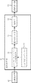
図1は、実施の形態1による目標追尾装置の構成を示すブロック図である。
図1において、10は受信信号から目標の信号(即ち、目標で反射されてくるレーダー信号)を検出するための目標検出器(目標検出手段)、20は目標検出器(目標検出手段)10が検出する検出信号に対し追尾処理を行うための追尾処理器(追尾処理手段)、30は追尾処理器(追尾処理手段)20により得られる追尾処理の結果(即ち、航跡)を表示するための航跡表示器(航跡表示手段)である。
Embodiment 1 FIG.
Embodiment 1 of the present invention will be described below with reference to the drawings.
FIG. 1 is a block diagram showing the configuration of the target tracking device according to the first embodiment.
In FIG. 1,
追尾処理器(追尾処理手段)20は、目標検出器(目標検出手段)10が検出する検出信号に対してレンジサイドローブとの相関の程度を計算するためのレンジサイドローブ相関処理手段21、該レンジサイドローブ相関処理手段21がレンジサイドローブ相関処理を行う際に用いるレーダー装置のレンジサイドローブパターン22、レンジサイドローブ相関処理手段21によるレンジサイドローブ相関処理の結果から追尾処理器(追尾処理手段)20により検出された信号の重み付けを計算する重み付け計算手段23、追尾処理において、信号の観測ベクトルおよび重み付け(ウェイティング)計算手段23の計算結果を用いて仮説の信頼度計算を実施するためのMHT(Multiple Hypothesis Tracking)24で構成されている。
The tracking processor (tracking processing means) 20 includes a range side lobe correlation processing means 21 for calculating the degree of correlation with the detection signal detected by the target detector (target detecting means) 10 and the range side lobe, A tracking processor (tracking processing means) from the range
なお、前述したように、「時刻t−1の航跡」に対し、「時刻tに検出した目標の信号」が、「時刻t−1の航跡」の目標信号であると仮定した場合、その仮定を仮説という。
そして、その仮説は検出した信号分について発生する。
追尾動作を維持するためには、複数の仮説の中から航跡に対する目標信号を判定しなければならない。
従って、各仮説に対して、現在追尾中の目標である確率を計算し、航跡と目標信号との対応に様々な組み合わせが考えられて1つに決められない場合、確からしい複数の仮説を保持しながら追尾を維持する。このようなアルゴリズムを“MHT”という。
As described above, when it is assumed that the “target signal detected at time t” is the target signal of “track at time t−1” with respect to “the track at time t−1”. Is called a hypothesis.
The hypothesis is generated for the detected signal.
In order to maintain the tracking operation, the target signal for the wake must be determined from a plurality of hypotheses.
Therefore, for each hypothesis, the probability of being the target currently being tracked is calculated, and if there are various combinations for the correspondence between the track and the target signal and cannot be determined as one, multiple probable hypotheses are retained. While keeping track. Such an algorithm is referred to as “MHT”.
次に、動作について説明する。
まず、目標検出器10により検出された目標の信号が追尾処理器20へ出力される。
次に、目標検出器10から出力された信号は、追尾処理器20において、以前の追尾結果から算出された目標の予測位置と目標検出器10から出力される信号との相関を計算し、追尾対象となる目標の信号を算出する追尾処理を行う。
追尾処理の際に、レンジサイドローブによる誤目標追尾を抑圧するため、レンジサイドローブ相関処理手段21は、検出した目標の観測ベクトルとS/N比からレンジサイドローブパターン22との相関を計算し、レンジサイドローブである確からしさを求め、レンジサイドローブである確からしさが高い目標については相関対象から外す処理を行う。
Next, the operation will be described.
First, a target signal detected by the
Next, the signal output from the
In order to suppress erroneous target tracking due to the range side lobe during the tracking process, the range side lobe correlation processing means 21 calculates the correlation between the range
以上の追尾処理の結果から、次に目標検出器から検出される信号の位置を予測し、前述の追尾処理を繰り返すことにより追尾維持を行う。
このように、本実施の形態においては、レンジサイドローブによる誤目標追尾が抑圧できるため、レンジサイドローブ自体を抑圧する際に生じる、信号レベルの劣化を防ぐことができ、レーダーの性能は向上することが期待できる。
From the result of the above tracking process, the position of the signal detected from the target detector is predicted next, and tracking is maintained by repeating the above tracking process.
As described above, in the present embodiment, it is possible to suppress erroneous target tracking by the range side lobe, so that it is possible to prevent signal level deterioration that occurs when the range side lobe itself is suppressed, and the radar performance is improved. I can expect that.
レンジサイドローブパターン22の適用方法について説明する。
レンジサイドローブパターン22は、予めシミュレーション等により、ビームごとに、ノイズフリーで第1サイドローブから第kサイドローブ(kはパラメータ)までのメインローブとのレンジ差ΔRk、S/N差ΔPkを求めておく。
A method for applying the range
The range
図2は、レンジサイドローブで検出された信号(不要信号)を判別するための重み付け算出フローを示す図である。
また、重み付けを考慮したMHTの信頼度計算を式(1)に示す。
なお、MHT信頼度計算式を示す式(1)において、Pl(Zm)およびPs(Zm)が重み付けに相当している。
FIG. 2 is a diagram illustrating a weight calculation flow for determining a signal (unnecessary signal) detected by the range side lobe.
Also, MHT reliability calculation considering weighting is shown in Equation (1).
In the equation (1) showing the MHT reliability calculation formula, Pl (Zm) and Ps (Zm) correspond to weighting.
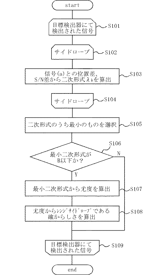
図2のフローチャートに基づいて、本実施の形態における重み付け算出ステップについて説明する。
まず、当該信号(即ち、目標検出器10にて検出された信号)を中心にした所定の距離、方位角、仰角のゲート内に、当該信号のS/N比より大きい信号(信号(a)と呼ぶ)の有無を調べる。(ステップS101)
信号(a)が無い場合、当該信号については、重み付けを行わないが、信号(a)が有る場合、当該信号についてレンジ差およびS/N差から、レンジサイドローブパターンにおいて、該当すると思われるレンジサイドローブを抽出する。(ステップS102)
Based on the flowchart of FIG. 2, the weight calculation step in this Embodiment is demonstrated.
First, a signal larger than the S / N ratio of the signal (signal (a)) in a gate having a predetermined distance, azimuth angle, and elevation angle centered on the signal (that is, a signal detected by the target detector 10). Is called). (Step S101)
When there is no signal (a), no weighting is performed on the signal, but when there is the signal (a), the range considered to be applicable in the range sidelobe pattern from the range difference and S / N difference for the signal. Extract side lobes. (Step S102)
レンジサイドローブ相関処理手段21は、抽出されたレンジサイドローブパターンと当該信号について相関を実施し、重み付け計算手段23は、相関結果により信号の重み付け(レンジサイドローブである確率:Ps、目標である確率:Pt)を算出する。
ステップS101において、目標検出器10にて検出された信号を中心にした所定の距離、方位角、仰角のゲート内に、当該信号のS/N比より大きい信号(信号(a)が有る場合、当該信号とレンジサイドローブのレンジ差△RkおよびS/N比の差△Pkから、当該信号と信号(a)とのレンジ差△R0およびS/N比の差△P0との分散値を算出し、パラメータとして設定しているレンジ差およびS/N比の差の分散値σRk2、σPk2と比較した結果を式(2)の2次形式λkとして算出する。
信号(a)に対して、第1レンジサイドローブから第nレンジサイドローブについて、式(2)を算出する。(ステップS103)
The range side lobe correlation processing means 21 performs correlation on the extracted range side lobe pattern and the signal, and the weight calculation means 23 weights the signal based on the correlation result (probability of being a range side lobe: Ps, target). Probability: Pt) is calculated.
In step S101, when a signal (signal (a) larger than the S / N ratio of the signal is present in a gate having a predetermined distance, azimuth angle, and elevation angle centered on the signal detected by the
For the signal (a), Equation (2) is calculated for the first range side lobe to the nth range side lobe. (Step S103)
次に、S103において算出したサイドローブ(ステップS104)について最もλkが小さい値(λmin)となるものを選択し(ステップS105)、選択したサイドローブのλminが所定の閾値(B)以下であるかを判定する。(ステップS106)
ステップS106での判定後、λminが所定の閾値(B)以下でない場合には、レンジサイドローブとの相関はなく、目標とは異なるとして扱う。
ステップS106での判定後、λminが所定の閾値(B)以下であると判定した場合は、正規分布の密度関数から尤度gを式(3)に基づいて算出する。(ステップS107)
Next, the side lobe calculated in S103 (step S104) having the smallest value (λmin) is selected (step S105), and whether the selected side lobe λmin is equal to or smaller than a predetermined threshold (B). Determine. (Step S106)
If λmin is not less than or equal to the predetermined threshold (B) after the determination in step S106, there is no correlation with the range side lobe and it is treated as different from the target.
If it is determined that λmin is equal to or smaller than the predetermined threshold (B) after the determination in step S106, the likelihood g is calculated from the density function of the normal distribution based on Expression (3). (Step S107)
次に、ステップS107で求めた尤度gを用いて、式(4)のとおりレンジサイドローブである確率Psを算出する。 Next, using the likelihood g obtained in step S107, a probability Ps that is a range side lobe is calculated as shown in equation (4).
目標の信号である確率であるPtは、Pt=1−Psより求める。
Psは0から1の値でありね1に近いほどレンジサイドローブである可能性が高いと見なす。
重み付けについては、式(1)のMHT信頼度計算式にステップ106で求めた確率が反映されている。
レンジサイドローブである確率Psが大きいならば、当該信号を不要信号として扱い、航跡確立の確立を低くし、誤航跡の発生を抑圧する。
Pt, which is the probability of being a target signal, is obtained from Pt = 1−Ps.
Ps is a value from 0 to 1, and the closer to 1, the higher the possibility of being a range side lobe.
As for the weighting, the probability obtained in
If the probability Ps of the range side lobe is large, the signal is treated as an unnecessary signal, the establishment of wake establishment is lowered, and the occurrence of erroneous wakes is suppressed.
以上説明したように、本実施の形態による目標追尾装置は、目標の信号を検出する目標検出手段(目標検出器)10と、目標検出手段10により検出した目標の信号に対してレーダー装置のレンジサイドローブパターンからレンジサイドローブ相関処理によりレンジサイドローブとの相関の程度を計算するレンジサイドローブ相関処理手段21、該レンジサイドローブ相関処理手段21の相関計算結果から目標検出手段10により検出した目標の信号に対して重み付け計算を行う重み付け計算手段23、該重み付け計算手段23による重み付け計算の結果を反映して検出した信号の仮説の信頼度計算を実施して目標の信号の誤検出を抑圧するMHT(Multiple Hypothesis Tracking)で構成され、目標の追尾処理を行う追尾処理手段(追尾処理器)20と、該追尾処理手段20による目標対追尾結果を表示する航跡表示手段(航跡表示器)30を備えている。
As described above, the target tracking device according to the present embodiment includes a target detection unit (target detector) 10 that detects a target signal, and a range of the radar device with respect to the target signal detected by the
従って、本実施の形態によれば、パルス圧縮におけるウェイティングをすることなく、レンジサイドローブにより発生する誤航跡を抑圧することが可能であり、ウェイティングによる信号レベルの劣化を防ぐことができる。 Therefore, according to the present embodiment, it is possible to suppress erroneous wakes caused by range side lobes without performing weighting in pulse compression, and it is possible to prevent signal level deterioration due to weighting.
この発明は、ウェイティングによる信号レベルの劣化を防ぐことができる目標追尾装置の実現に有用である。 The present invention is useful for realizing a target tracking device that can prevent signal level deterioration due to weighting.
10 目標検出器(目標検出手段)
20 追尾処理器(追尾処理手段)
21 レンジサイドローブ相関処理手段
22 レンジサイドローブパターン
23 重み付け(ウェイティング)計算手段
24 MHT(Multiple Hypothesis Tracking)
30 航跡表示器(航跡表示手段)
10 Target detector (target detection means)
20 Tracking processor (tracking processing means)
21 Range side lobe correlation processing means 22 Range
30 Wake display (Wake display means)
Claims (2)
上記目標検出手段により検出した上記目標の信号に対してレーダー装置のレンジサイドローブパターンからレンジサイドローブ相関処理によりレンジサイドローブとの相関の程度を計算するレンジサイドローブ相関処理手段、上記レンジサイドローブ相関処理手段の相関計算結果から上記目標検出手段により検出した上記目標の信号に対して重み付け計算を行う重み付け計算手段、上記重み付け計算手段による重み付け計算の結果を反映して検出した信号の仮説の信頼度計算を実施して上記目標の信号の誤検出を抑圧するMHT(Multiple Hypothesis Tracking)で構成され、上記目標の追尾処理を行う追尾処理手段と、
上記追尾処理手段による目標対追尾結果を表示する航跡表示手段を備えたことを特徴とする目標追尾装置。 Target detection means for detecting a target signal;
Range side lobe correlation processing means for calculating the degree of correlation with the range side lobe by range side lobe correlation processing from the range side lobe pattern of the radar device with respect to the target signal detected by the target detection means; Weight calculation means for performing weight calculation on the target signal detected by the target detection means from the correlation calculation result of the correlation processing means, and reliability of the hypothesis of the signal detected by reflecting the result of the weight calculation by the weight calculation means Tracking processing means for performing tracking processing of the target, comprising MHT (Multiple Hypothesis Tracking) that performs degree calculation and suppresses false detection of the target signal;
A target tracking device comprising a track display means for displaying a target-to-track result by the tracking processing means.
上記目標検出ステップにおいて検出した上記目標の信号に対してレーダー装置のレンジサイドローブパターンからレンジサイドローブ相関処理によりレンジサイドローブとの相関の程度を計算するレンジサイドローブ相関処理ステップ、上記レンジサイドローブ相関処理ステップにおける相関計算結果から上記目標検出ステップにおいて検出した上記目標の信号に対して重み付け計算を行う重み付け計算ステップ、上記重み付け計算ステップにおける重み付け計算の結果を反映して検出した信号の仮説の信頼度計算を実施して上記目標の信号の誤検出を抑圧するMHT(Multiple Hypothesis Tracking)処理ステップを有し、上記目標の追尾処理を行う追尾処理ステップと、
上記追尾処理ステップにおける目標対追尾結果を表示する航跡表示ステップからなることを特徴とする目標追尾方法。 A target detection step for detecting a target signal;
Range side lobe correlation processing step for calculating the degree of correlation with the range side lobe by range side lobe correlation processing from the range side lobe pattern of the radar device with respect to the target signal detected in the target detection step; A weighting calculation step for performing weighting calculation on the target signal detected in the target detection step from the correlation calculation result in the correlation processing step, and reliability of the hypothesis of the signal detected by reflecting the result of the weighting calculation in the weighting calculation step A tracking processing step for performing tracking processing of the target, including a MHT (Multiple Hypothesis Tracking) processing step for performing degree calculation and suppressing erroneous detection of the target signal;
A target tracking method comprising a track display step for displaying a target-to-track result in the tracking processing step.
Priority Applications (1)
| Application Number | Priority Date | Filing Date | Title |
|---|---|---|---|
| JP2008176969A JP5379415B2 (en) | 2008-07-07 | 2008-07-07 | Target tracking device and target tracking method |
Applications Claiming Priority (1)
| Application Number | Priority Date | Filing Date | Title |
|---|---|---|---|
| JP2008176969A JP5379415B2 (en) | 2008-07-07 | 2008-07-07 | Target tracking device and target tracking method |
Publications (2)
| Publication Number | Publication Date |
|---|---|
| JP2010014664A true JP2010014664A (en) | 2010-01-21 |
| JP5379415B2 JP5379415B2 (en) | 2013-12-25 |
Family
ID=41700897
Family Applications (1)
| Application Number | Title | Priority Date | Filing Date |
|---|---|---|---|
| JP2008176969A Active JP5379415B2 (en) | 2008-07-07 | 2008-07-07 | Target tracking device and target tracking method |
Country Status (1)
| Country | Link |
|---|---|
| JP (1) | JP5379415B2 (en) |
Cited By (2)
| Publication number | Priority date | Publication date | Assignee | Title |
|---|---|---|---|---|
| CN111289954A (en) * | 2020-03-31 | 2020-06-16 | 四川长虹电器股份有限公司 | Point cloud division and track matching method for millimeter wave radar target tracking |
| CN113589252A (en) * | 2021-08-03 | 2021-11-02 | 东风汽车集团股份有限公司 | Multi-radar sensor multi-target tracking method based on MHT algorithm |
Citations (16)
| Publication number | Priority date | Publication date | Assignee | Title |
|---|---|---|---|---|
| JPS58113773A (en) * | 1981-12-26 | 1983-07-06 | Mitsubishi Electric Corp | Pulse compressing radar |
| JPS58195172A (en) * | 1982-05-08 | 1983-11-14 | Mitsubishi Electric Corp | Radar device |
| JPH04113290A (en) * | 1990-09-04 | 1992-04-14 | Tech Res & Dev Inst Of Japan Def Agency | Multi-target homing method and device thereof |
| JPH10115678A (en) * | 1996-10-15 | 1998-05-06 | Mitsubishi Electric Corp | Equipment for correlation integration of target |
| JPH10197624A (en) * | 1997-01-16 | 1998-07-31 | Tech Res & Dev Inst Of Japan Def Agency | Signal extraction unit |
| JPH11231043A (en) * | 1998-02-17 | 1999-08-27 | Tech Res & Dev Inst Of Japan Def Agency | Pulse compression method and device thereof |
| JP2000221265A (en) * | 1999-02-03 | 2000-08-11 | Mitsubishi Electric Corp | Target correlation integrating device |
| JP2002098755A (en) * | 2000-09-22 | 2002-04-05 | Mitsubishi Electric Corp | Device for tracking target |
| JP2002328164A (en) * | 2001-05-02 | 2002-11-15 | Mitsubishi Electric Corp | Target tracking method and radar system |
| JP2004144543A (en) * | 2002-10-23 | 2004-05-20 | Omron Corp | Method and device for detecting object |
| JP2004219300A (en) * | 2003-01-16 | 2004-08-05 | Mitsubishi Electric Corp | Target-tracking system |
| JP2005127977A (en) * | 2003-10-27 | 2005-05-19 | Mitsubishi Electric Corp | Target tracking system |
| JP2005148051A (en) * | 2003-10-22 | 2005-06-09 | Mitsubishi Electric Corp | Unwanted signal suppressor |
| WO2006013689A1 (en) * | 2004-08-06 | 2006-02-09 | Murata Manufacturing Co., Ltd. | Radar |
| JP2007040953A (en) * | 2005-06-30 | 2007-02-15 | Toshiba Corp | Correlation reception processor |
| JP2009128278A (en) * | 2007-11-27 | 2009-06-11 | Japan Radio Co Ltd | Pulse compression radar device |
-
2008
- 2008-07-07 JP JP2008176969A patent/JP5379415B2/en active Active
Patent Citations (16)
| Publication number | Priority date | Publication date | Assignee | Title |
|---|---|---|---|---|
| JPS58113773A (en) * | 1981-12-26 | 1983-07-06 | Mitsubishi Electric Corp | Pulse compressing radar |
| JPS58195172A (en) * | 1982-05-08 | 1983-11-14 | Mitsubishi Electric Corp | Radar device |
| JPH04113290A (en) * | 1990-09-04 | 1992-04-14 | Tech Res & Dev Inst Of Japan Def Agency | Multi-target homing method and device thereof |
| JPH10115678A (en) * | 1996-10-15 | 1998-05-06 | Mitsubishi Electric Corp | Equipment for correlation integration of target |
| JPH10197624A (en) * | 1997-01-16 | 1998-07-31 | Tech Res & Dev Inst Of Japan Def Agency | Signal extraction unit |
| JPH11231043A (en) * | 1998-02-17 | 1999-08-27 | Tech Res & Dev Inst Of Japan Def Agency | Pulse compression method and device thereof |
| JP2000221265A (en) * | 1999-02-03 | 2000-08-11 | Mitsubishi Electric Corp | Target correlation integrating device |
| JP2002098755A (en) * | 2000-09-22 | 2002-04-05 | Mitsubishi Electric Corp | Device for tracking target |
| JP2002328164A (en) * | 2001-05-02 | 2002-11-15 | Mitsubishi Electric Corp | Target tracking method and radar system |
| JP2004144543A (en) * | 2002-10-23 | 2004-05-20 | Omron Corp | Method and device for detecting object |
| JP2004219300A (en) * | 2003-01-16 | 2004-08-05 | Mitsubishi Electric Corp | Target-tracking system |
| JP2005148051A (en) * | 2003-10-22 | 2005-06-09 | Mitsubishi Electric Corp | Unwanted signal suppressor |
| JP2005127977A (en) * | 2003-10-27 | 2005-05-19 | Mitsubishi Electric Corp | Target tracking system |
| WO2006013689A1 (en) * | 2004-08-06 | 2006-02-09 | Murata Manufacturing Co., Ltd. | Radar |
| JP2007040953A (en) * | 2005-06-30 | 2007-02-15 | Toshiba Corp | Correlation reception processor |
| JP2009128278A (en) * | 2007-11-27 | 2009-06-11 | Japan Radio Co Ltd | Pulse compression radar device |
Non-Patent Citations (1)
| Title |
|---|
| JPN6012043445; 小幡 康 , 亀田 洋志 , 系 正義 , 辻道 信吾 , 小菅 義夫: '航跡型MHTによる追尾開始性能のシミュレーション評価' 電子情報通信学会技術研究報告. SANE, 宇宙・航行エレクトロニクス 99(654), 20000225, 79-86, 社団法人電子情報通信学会 * |
Cited By (2)
| Publication number | Priority date | Publication date | Assignee | Title |
|---|---|---|---|---|
| CN111289954A (en) * | 2020-03-31 | 2020-06-16 | 四川长虹电器股份有限公司 | Point cloud division and track matching method for millimeter wave radar target tracking |
| CN113589252A (en) * | 2021-08-03 | 2021-11-02 | 东风汽车集团股份有限公司 | Multi-radar sensor multi-target tracking method based on MHT algorithm |
Also Published As
| Publication number | Publication date |
|---|---|
| JP5379415B2 (en) | 2013-12-25 |
Similar Documents
| Publication | Publication Date | Title |
|---|---|---|
| JP4670446B2 (en) | Radar signal processing apparatus and CFAR processing method used therefor | |
| US9453911B2 (en) | Target tracking system and target tracking method | |
| RU2004130472A (en) | ADAPTIVE SYSTEM AND METHOD FOR DETECTING OBJECTIVES | |
| JP2009250616A (en) | Radar signal processing device | |
| JP2008170287A (en) | Radar device | |
| KR20160094728A (en) | Appratus and method for generating global satellite system solution | |
| KR20140083568A (en) | CFAR detection method with reference cell division average scheme and radar system using the same | |
| JP5379415B2 (en) | Target tracking device and target tracking method | |
| JP2010276475A (en) | Target tracking apparatus and target tracking method | |
| JP2013007578A (en) | Signal detection device, signal detection method and signal detection program | |
| US8416118B1 (en) | Chaff cloud detection and centroid estimation | |
| KR101041926B1 (en) | Method for noise jammer estimation by using local minimum selection | |
| JP2005337732A (en) | Radar device | |
| KR102011959B1 (en) | Method and Apparatus for Processing Radar Received Signal for Detecting Interference Signals in Pulse Compression Process | |
| KR102092278B1 (en) | 2D GO CA-CFAR detection method for detecting targets in heterogeneous clutter environments and system thereof | |
| JP2007232412A (en) | Object detecting apparatus | |
| KR20070016394A (en) | Method for detecting jamming for target tracking by using the detection zone data | |
| JP2009250925A (en) | Radar signal processing device | |
| JP5991599B2 (en) | Target detection device | |
| JP6031269B2 (en) | Noise suppression device, noise suppression method, and noise suppression program | |
| KR102049402B1 (en) | Method and apparatus for processing signal based CFAR in radar system | |
| JP4046713B2 (en) | Signal processor for frequency modulation radar | |
| KR102216650B1 (en) | CFAR detecting method based on adaptive guard cell selection and system thereof | |
| KR101740363B1 (en) | Wake detectors and wake detecting method thereof | |
| JP4541817B2 (en) | Radar signal processing device |
Legal Events
| Date | Code | Title | Description |
|---|---|---|---|
| A621 | Written request for application examination |
Free format text: JAPANESE INTERMEDIATE CODE: A621 Effective date: 20110520 |
|
| A977 | Report on retrieval |
Free format text: JAPANESE INTERMEDIATE CODE: A971007 Effective date: 20120523 |
|
| A131 | Notification of reasons for refusal |
Free format text: JAPANESE INTERMEDIATE CODE: A131 Effective date: 20120821 |
|
| A521 | Request for written amendment filed |
Free format text: JAPANESE INTERMEDIATE CODE: A523 Effective date: 20120927 |
|
| TRDD | Decision of grant or rejection written | ||
| A01 | Written decision to grant a patent or to grant a registration (utility model) |
Free format text: JAPANESE INTERMEDIATE CODE: A01 Effective date: 20130903 |
|
| A61 | First payment of annual fees (during grant procedure) |
Free format text: JAPANESE INTERMEDIATE CODE: A61 Effective date: 20130927 |
|
| R151 | Written notification of patent or utility model registration |
Ref document number: 5379415 Country of ref document: JP Free format text: JAPANESE INTERMEDIATE CODE: R151 |
|
| R250 | Receipt of annual fees |
Free format text: JAPANESE INTERMEDIATE CODE: R250 |
|
| R250 | Receipt of annual fees |
Free format text: JAPANESE INTERMEDIATE CODE: R250 |
|
| R250 | Receipt of annual fees |
Free format text: JAPANESE INTERMEDIATE CODE: R250 |
|
| R250 | Receipt of annual fees |
Free format text: JAPANESE INTERMEDIATE CODE: R250 |
|
| R250 | Receipt of annual fees |
Free format text: JAPANESE INTERMEDIATE CODE: R250 |
|
| R250 | Receipt of annual fees |
Free format text: JAPANESE INTERMEDIATE CODE: R250 |
|
| R250 | Receipt of annual fees |
Free format text: JAPANESE INTERMEDIATE CODE: R250 |
|
| R250 | Receipt of annual fees |
Free format text: JAPANESE INTERMEDIATE CODE: R250 |