JP2010014543A - System for collecting and selecting oscilloscope data - Google Patents
System for collecting and selecting oscilloscope data Download PDFInfo
- Publication number
- JP2010014543A JP2010014543A JP2008174700A JP2008174700A JP2010014543A JP 2010014543 A JP2010014543 A JP 2010014543A JP 2008174700 A JP2008174700 A JP 2008174700A JP 2008174700 A JP2008174700 A JP 2008174700A JP 2010014543 A JP2010014543 A JP 2010014543A
- Authority
- JP
- Japan
- Prior art keywords
- oscilloscope
- signal
- data
- unit
- input
- Prior art date
- Legal status (The legal status is an assumption and is not a legal conclusion. Google has not performed a legal analysis and makes no representation as to the accuracy of the status listed.)
- Granted
Links
- 239000000284 extract Substances 0.000 claims abstract description 6
- 238000005070 sampling Methods 0.000 claims description 22
- 238000013480 data collection Methods 0.000 claims description 15
- 230000004913 activation Effects 0.000 claims description 13
- 101710154918 Trigger factor Proteins 0.000 claims description 7
- 238000013075 data extraction Methods 0.000 claims description 7
- 230000007257 malfunction Effects 0.000 abstract 1
- 238000010586 diagram Methods 0.000 description 10
- 230000001960 triggered effect Effects 0.000 description 3
- 238000006243 chemical reaction Methods 0.000 description 2
- 230000007274 generation of a signal involved in cell-cell signaling Effects 0.000 description 1
Images


Abstract
Description
この発明は、電力系統(以下、系統と略す)の電流や電圧を記録し、事故等リレーの動作時に電流や電圧の情報を出力するオシロデータ装置において、特に、系統のアナログ電圧、電流のサンプリングデータを含むオシロデータを生成するオシロ装置と、このオシロデータをネットワーク等を経由して収集し、必要なデータを選択するオシロサーバーとで構成されるオシロデータ収集選択装置に関する。 The present invention relates to an oscillodata device that records current and voltage of a power system (hereinafter abbreviated as “system”) and outputs current and voltage information when a relay such as an accident is operated, in particular, analog voltage and current sampling of the system. The present invention relates to an oscilloscope data collection / selection device including an oscilloscope device that generates oscilloscope data including data and an oscilloscope server that collects the oscilloscope data via a network and selects necessary data.
オシロ装置は、信号入力チャンネルに系統の電圧信号、電流信号が入力し、これをサンプリングしてメモリに順次記憶していく。オシロ装置は、さらに、接点入力チャンネルを備えており、このポートに、系統の適当な箇所に設けられているリレー等の接点入力信号が入力する。通常は、信号入力チャンネル、接点入力チャンネルは各々複数個設けられており、接点入力チャンネルのいずれかに入力している接点入力信号がオン(リレー接点がオン)すると、その信号をトリガー信号としてメモリに記憶されているサンプリングデータを所定期間分(トリガー信号の前後の所定期間分)含むオシロデータが生成されて出力される。 The oscilloscope device inputs a system voltage signal and current signal to a signal input channel, samples them, and stores them in a memory sequentially. The oscilloscope further includes a contact input channel, and a contact input signal such as a relay provided at an appropriate location of the system is input to this port. Normally, there are multiple signal input channels and contact input channels, and when the contact input signal input to one of the contact input channels is on (relay contact is on), that signal is stored as a trigger signal. The oscilloscope data including the sampling data stored in a predetermined period (a predetermined period before and after the trigger signal) is generated and output.
オシロサーバーでは、このオシロデータを収集して、系統での事故等発生時における波形解析を行うことが可能になる。 The oscillo server can collect this oscilloscope data and perform waveform analysis when an accident or the like occurs in the system.
図1は、従来のオシロデータ収集選択装置の構成図である。 FIG. 1 is a block diagram of a conventional oscilloscope data collection / selection apparatus.
このオシロデータ収集選択装置は、オシロ装置1とオシロサーバー2とで構成され、これらがネットワーク回線3で接続されている。
The oscilloscope data collection / selection device includes an
オシロ装置1は、複数の信号入力チャンネルAC1〜ACn分の電圧信号、電流信号を受ける信号入力端子と、複数の接点入力チャンネルDI1〜DIm分の接点入力信号を受ける接点入力端子を備えている。信号入力チャンネルAC1〜ACnには、それぞれ、系統内のセンサで検出した電圧信号や電流信号が入力し、接点入力チャンネルDI1〜DImには、系統内に設けられているリレートリップ等の接点入力信号が入力する。
The
オシロ装置は、図2に示すようなグルーピングテーブル4を備えている。このグルーピングテーブル4は、信号入力(チャンネル)と接点入力(チャンネル)をそれぞれ関連する入力要素毎のグループ1〜k(この図ではk=20)にグループ分けするのに用いる。各グループは、事故時等の波形解析に必要な入力要素をまとめてあり、いずれかの接点入力チャンネルに接点入力信号があるとその信号がトリガーとなって、そのグループの信号入力チャンネルに入力している信号(サンプリングデータ)をオシロデータにしてオシロサーバー2に出力する。
The oscilloscope includes a grouping table 4 as shown in FIG. This grouping table 4 is used to group signal inputs (channels) and contact inputs (channels) into
このように、グルーピングテーブル4をオシロ装置1に設けることによって、トリガー要因毎に、解析に必要なオシロデータだけを選択してオシロサーバー2に出力することができる。
In this way, by providing the grouping table 4 in the
また、図3に示すように、入力チャンネル数の少ない複数のオシロユニット10〜12を使用し、系統の全ての電圧/電流信号と接点入力信号を各オシロユニットに分割するオシロデータ収集選択装置も提案されている。この装置では、各オシロユニットにグルーピングテーブルが設けられている。
Further, as shown in FIG. 3, there is also an oscilloscope data collection and selection device that uses a plurality of
さらに、複数のオシロユニットを1つのオシロサーバーに接続し、各オシロ装置からのオシロデータをオシロサーバーに集めて、オシロユニット間の波形解析を行う装置が提案されている(特許文献1)。この装置では、各オシロユニット間をユニット間起動インターフェイス端子で接続し、いずれかのオシロユニットでトリガー信号が発生すると、他のオシロユニットに対してもそのトリガー信号を送信する。これにより、全てのオシロユニットからオシロデータを受信することにより、オシロユニット間の波形解析を可能にする。
しかしながら、図1に示す装置では、オシロ装置1とオシロサーバー2との関係が1対1であるため、次の問題がある。
However, the device shown in FIG. 1 has the following problem because the relationship between the
すなわち、信号入力チャンネル数が多数あるオシロ装置1を小さな系統で使用する場合は、チャンネル数が余ってしまうため、コスト高になる。また、信号入力チャンネル数が多数あるオシロ装置1を大きな系統で使用する場合は、オシロ装置が停止しているとき、系統に故障等が発生しトリガー信号が発生するような事象が発生しても、全部のチャンネルが無効となるためにシステム全体に及ぼす影響が大きくなる。
That is, when the
また、図3に示す装置では、故障発生時に全部のオシロユニットを停止する必要はないが、系統の全ての電圧/電流信号と接点入力信号を各オシロユニットに分割しているために、図1に示す装置に比較して、グルーピングに制限がある。例えば、オシロユニット10は、オシロユニット11への接点入力信号でトリガーすることは出来ない。
In the apparatus shown in FIG. 3, it is not necessary to stop all the oscilloscope units when a failure occurs. However, since all the voltage / current signals and contact input signals of the system are divided into each oscilloscope unit, FIG. Compared with the device shown in Fig. 4, there is a limitation in grouping. For example, the
さらに、特許文献1に示す装置は、オシロデータ収集選択装置にグルーピングテーブルを備えるものではないために、事故毎に解析に必要なオシロデータだけを抽出することができない。
Furthermore, since the apparatus shown in
そこで、この発明の目的は、信号入力チャンネル数が系統の規模に応じたものにできる柔軟な構成を備え、また、故障時においてはシステム全体に及ぼす影響が小さくて済むオシロデータ収集選択装置を提供することにある。 Therefore, an object of the present invention is to provide an oscilloscope data collection / selection device that has a flexible configuration in which the number of signal input channels can be adjusted according to the scale of the system, and can have a small influence on the entire system in the event of a failure. There is to do.
この発明のオシロデータ収集選択装置は、複数個のオシロユニットと、オシロサーバーとで構成される。 The oscilloscope data collection / selection device of the present invention comprises a plurality of oscilloscope units and an oscilloserver.
オシロユニットは、少なくとも1つ以上の信号入力チャンネル分の電流信号又は電圧信号を受ける信号入力端子と、少なくとも1つ以上の接点入力チャンネル分の接点入力信号を受ける接点入力端子と、ユニット間起動インターフェイス端子と、前記信号入力チャンネルに入力した電流信号又は電圧信号のサンプリングデータを記憶するメモリとを備え、トリガー信号に基づいて、前記メモリに記憶されているサンプリングデータを含むオシロデータを出力する。 The oscillo-unit includes a signal input terminal that receives a current signal or a voltage signal for at least one signal input channel, a contact input terminal that receives a contact input signal for at least one contact input channel, and an inter-unit activation interface A terminal and a memory for storing sampling data of a current signal or a voltage signal input to the signal input channel are provided, and oscilloscope data including the sampling data stored in the memory is output based on a trigger signal.
オシロサーバーは、前記オシロデータの中から、予め設定したグルーピングテーブルに基づいて特定のオシロデータを抽出するオシロデータ抽出部を備える。 The oscillo server includes an oscillo data extraction unit that extracts specific oscilloscope data from the oscilloscope data based on a preset grouping table.
前記複数個のオシロユニットの各々のユニット間起動インターフェイス端子は、ユニット間で相互に接続され、接点入力チャンネルで接点入力信号を受けると前記トリガー信号を生成して全オシロユニットに出力する。 The inter-unit activation interface terminals of each of the plurality of oscilloscope units are connected to each other. When a contact input signal is received through a contact input channel, the trigger signal is generated and output to all oscilloscope units.
前記オシロサーバーのグルーピングテーブルの各グループは、信号入力チャンネルと接点入力チャンネルをオシロユニットのユニット番号とともに記憶し、
前記オシロサーバーのオシロデータ抽出部は、各グループのいずれかの接点入力チャンネルでの入力があると、そのグループの信号入力チャンネルからのサンプリングデータを含むオシロデータを前記特定のオシロデータとして抽出する。
Each group of the oscilloserver grouping table stores the signal input channel and the contact input channel together with the unit number of the oscilloscope unit,
When there is an input in any contact input channel of each group, the oscillo data extraction unit of the oscillo server extracts oscilloscope data including sampling data from the signal input channel of the group as the specific oscilloscope data.
なお、前記複数個のオシロユニットは、トリガー信号発生時においての、オシロユニット番号と、トリガー信号が接点入力チャンネルに入力した接点入力信号に基づくものか前記ユニット間起動インターフェイス端子で受信されたものか否かを識別するトリガー要因データと、所定期間のサンプリングデータと、接点入力信号とを含むオシロデータを出力する。 Whether the plurality of oscilloscope units are based on the oscilloscope unit number at the time of trigger signal generation and the contact input signal input to the contact input channel or received by the inter-unit activation interface terminal Oscilloscope data including trigger factor data for identifying whether or not, sampling data for a predetermined period, and a contact input signal is output.
この発明のオシロデータ収集選択装置は、複数のオシロユニット間がユニット間起動インターフェイスにより接続されていて、いずれかのオシロユニットで接点入力信号を受けると、全てのユニットにトリガー信号が送信される。このとき、全てのオシロユニットからオシロサーバーに対してオシロデータが出力される。オシロサーバーでは、受信したオシロデータから、グルーピングテーブルに基づいて特定のオシロデータを抽出する。 In the oscilloscope data collection / selection device of the present invention, a plurality of oscilloscope units are connected by an inter-unit activation interface, and when a contact input signal is received by any oscilloscope unit, a trigger signal is transmitted to all units. At this time, the oscilloscope data is output from all oscilloscope units to the oscilloscope server. The oscillo server extracts specific oscilloscope data from the received oscilloscope data based on the grouping table.
オシロサーバーのグルーピングテーブルは、図2に示すようなテーブルと類似しているが、各セルには、オシロユニットのユニット番号が付加されている。このようにすることで、トリガー要因となった接点入力チャンネルのグループの特定と、そのグループ内に含まれる信号入力チャンネルの特定を行うことができる。 The grouping table of the oscilloserver is similar to the table shown in FIG. 2, but the unit number of the oscilloscope unit is added to each cell. By doing so, it is possible to specify a group of contact input channels that are trigger factors and to specify a signal input channel included in the group.
この発明によれば、系統の規模に応じた最適な数のオシロユニットを設定することができ、全体としてシステムのコストアップを防ぐことができるとともに、故障時においてはシステム全体に及ぼす影響を小さくすることができる。 According to the present invention, it is possible to set an optimal number of oscilloscope units according to the scale of the system, and it is possible to prevent an increase in the cost of the system as a whole and to reduce the influence on the entire system in the event of a failure. be able to.
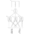
図4は、この発明の実施形態であるオシロデータ収集選択装置の概略構成図である。 FIG. 4 is a schematic configuration diagram of an oscilloscope data collection / selection apparatus according to an embodiment of the present invention.
同図において、複数のオシロユニット10〜13・・・Nは、それぞれ系統の適切な箇所に設置されている。これらのオシロユニット10〜13・・・Nから出力されるオシロデータは、ネットワーク3を介してオシロサーバー20に入力される。
In the figure, each of the plurality of oscilloscope units 10-13... N is installed at an appropriate location of the system. The oscilloscope data output from the
各オシロユニットは、少なくとも1つ以上の信号入力チャンネルACn分の電流信号又は電圧信号を受ける入力信号受信端子と少なくとも1つ以上の接点入力チャンネルDIm分の接点入力信号を受ける接点信号受信端子と、1つのユニット間起動インターフェイス端子TPとを入力側に備えている。なお、この実施形態では、入力信号受信端子としてアナログ入力端子を採用しているが、後述のように(図9)、入力信号がデジタル信号の場合は、デジタル入力端子が採用され、直接サンプリングデータが入力される。後者の場合は、信号入力チャンネルACn分の電流信号又は電圧信号(サンプリングデータ)がデジタル入力端子にシリアルに入力される。 Each oscilloscope unit has an input signal receiving terminal for receiving a current signal or a voltage signal for at least one signal input channel ACn, and a contact signal receiving terminal for receiving a contact input signal for at least one contact input channel DIm; One inter-unit activation interface terminal TP is provided on the input side. In this embodiment, an analog input terminal is employed as an input signal receiving terminal. However, as will be described later (FIG. 9), when the input signal is a digital signal, a digital input terminal is employed, and direct sampling data is used. Is entered. In the latter case, a current signal or voltage signal (sampling data) for the signal input channel ACn is serially input to the digital input terminal.
各信号入力チャンネルACnと接点入力チャンネルDImは、ユニット毎に異なっていて、系統において相互に関係あるチャンネルがユニット毎に集められている。 Each signal input channel ACn and contact input channel DIm are different for each unit, and channels that are mutually related in the system are collected for each unit.
図5は、電力系統の一例を示している。例えば、図5において、甲母線30に関係するCT、PTからの電流信号や電圧信号は、図4のオシロユニット10の信号入力チャンネルACnに入力し、乙母線31に関係するCT、PTからの電流信号や電圧信号は、オシロユニット11の信号入力チャンネルACnに入力し、#1線路32に関係するCT、PTからの電流信号や電圧信号は、オシロユニット12の信号入力チャンネルACnに入力し、#2線路33に関係するCT、PTからの電流信号や電圧信号は、オシロユニット13の信号入力チャンネルACnに入力する。
FIG. 5 shows an example of the power system. For example, in FIG. 5, current signals and voltage signals from CT and PT related to the
また、甲母線保護用リレーの接点入力信号(リレートリップ信号)や乙母線保護用リレーの接点入力信号は、オシロサーバー20でのオシロデータの解析に役立ちやすいように、どのオシロユニットに入力するかが決められる。主に、前記信号入力チャンネルACnへ入力されたオシロユニットに、そのオシロユニットに関連する保護用リレーの接点入力信号が接続される。例えば、オシロユニット10が甲母線30に関係するなら、オシロユニット10の接点入力チャンネルには甲母線保護用リレーの接点が接続される。また、オシロユニット11が乙母線31に関係するなら、オシロユニット11の接点入力チャンネルには乙母線保護用リレーの接点が接続される。#1線路32、#2線路33の接点入力信号においても同様である。
In addition, to which oscilloscope unit the contact input signal (relay trip signal) of the bus protection relay and the contact input signal of the B bus protection relay are input so that the
こうすることで、例えば、オシロユニット10の接点入力チャンネルがトリガー要因であるときには、オシロユニット10自身の信号入力チャンネルACnが選択される。しかし、これだけで必要な電圧/電流信号データがすべて揃うわけではなく、これ以外に他のオシロユニット(例えばオシロユニット11)に入力された電圧/電流信号データが必要な場合がある。
Thus, for example, when the contact input channel of the
図6は、オシロユニット10の構成図である。他のオシロユニット11〜Nは、オシロユニット10と同じ構成にあるため、以下、オシロユニット10について説明する。
FIG. 6 is a configuration diagram of the
電圧信号又は電流信号を受ける入力信号受信端子T(ACn)には、A/D変換器100が接続され、ここで所定の分解能のデジタルデータにサンプリングされ、サンプリングデータは、パラレル−シリアル変換回路を介して(図示を略す)マイクロプロセッサ(MPU)101に入力する。
An A /
接点入力信号を受ける接点信号受信端子T(DIm)は、接点入力信号を受けるとトリガー信号を生成してMPU101に出力する。
When receiving the contact input signal, the contact signal receiving terminal T (DIm) that receives the contact input signal generates a trigger signal and outputs it to the
ユニット間起動インターフェイスTPは、MPU101に接続され、MPU101は、他のユニットから送られてきたトリガー信号を検出する。
The inter-unit activation interface TP is connected to the
メモリ102は、電圧/電流信号のサンプリングデータを信号入力チャンネル毎に一定の時間分記憶する。
The
ネットワークインターフェイス103は、MPU101からのオシロデータをネットワーク3に出力する。
The
以上の構成のオシロユニット10において、MPU101は、常時、電圧/電流信号を信号入力チャンネル毎にメモリ102に記憶していて、接点入力信号を検出すると、トリガー信号を生成してユニット間起動インターフェイスTPを介して他のユニットに出力する。また、そのトリガー信号によって、或いはユニット間起動インターフェイスTPで受信した他のユニットからのトリガー信号によってメモリ102に記憶されている信号入力チャンネル毎のサンプリングデータを含むオシロデータを作成し、これをネットワーク3を介してオシロサーバー20に出力する。
In the
他のオシロユニット11〜Nは、オシロユニット10からトリガー信号を受信すると、オシロユニット10と同様な動作を行う。すなわち、メモリ102に記憶されているサンプリングデータを含むオシロデータを作成し、これをネットワーク3を介してオシロサーバー20に出力する。
When the other oscilloscope units 11 to N receive the trigger signal from the
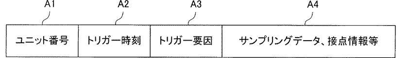
図7は、オシロデータの構成を示している。 FIG. 7 shows the structure of the oscilloscope data.
ユニット番号A1は、オシロユニットを識別するためのユニット番号であり、次の数値により示される。 The unit number A1 is a unit number for identifying the oscilloscope unit and is indicated by the following numerical value.
XXXn
ただし、
XXX ユニット番号
トリガー時刻A2は、トリガ信号の生成時又は受信時の時刻である。
XXXn
However,
XXX Unit Number The trigger time A2 is the time when the trigger signal is generated or received.
トリガー要因種別A3は、トリガー要因が接点入力信号によるものかどうかを識別する符号であり、次の数値により示される。 The trigger factor type A3 is a code for identifying whether or not the trigger factor is a contact input signal, and is indicated by the following numerical value.
0〜6 接点入力信号又は手動等による(接点入力信号は、例えば「0」)
7 ユニット間起動インターフェイスTPの受信による
サンプリングデータ・接点情報等A4は、トリガー前後一定時間のサンプリングデータ(各信号入力チャンネル毎)と、トリガー時の各接点入力信号の状態である。
0-6 Contact input signal or manually (contact input signal is “0”, for example)
7 Sampling data, contact information, etc. A4 by receiving the inter-unit activation interface TP are sampling data (for each signal input channel) for a predetermined time before and after the trigger and the state of each contact input signal at the time of the trigger.
例えば、オシロユニット10に入力するいずれかの接点入力信号によりトリガー信号が生成されると、全てのユニットにおいてトリガー時刻A2が同一のオシロデータが生成され、これらのオシロデータがオシロサーバー20に対して一斉に送信される。また、オシロユニット10のトリガー要因A3は、接点入力信号を示す0〜6から選ばれる数値となり、それ以外のオシロユニット11〜Nのトリガー要因は、「7」となる。
For example, when a trigger signal is generated by any contact input signal input to the
オシロサーバー20は、入力設定部200と、オシロデータ抽出部201とオシロデータ出力部202とを備えている。
The
オシロデータ抽出部201は、グルーピングテーブル201aを備えている。入力設定部200は、グルーピングテーブル201aの内容を任意に設定する部位であり、キーボード等で構成される。
The oscilloscope
図8は、グルーピングテーブル201aを示している。 FIG. 8 shows the grouping table 201a.
この例では、グルーピングテーブル201aは、グループ1〜グループ20に分けられていて、図2と同様に、各グループは、信号入力チャンネルと接点入力チャンネルをグループ分けしている。このテーブル201aが図2に示すテーブル4と相違する点は、テーブルの各セルに、信号入力チャンネル及び接点入力チャンネルの他にユニット番号XXXnを記憶している点である。このユニット番号XXXnは、セル内に記憶されている入力チャンネルACn又は接点入力チャンネルDImの位置(オシロユニット番号)を表す。
In this example, the grouping table 201a is divided into
グルーピングテーブル201aがこのように構成されていることにより、いずれかのオシロユニットでトリガーがかかったときに、全ユニットからオシロデータが送信されてきても、その中から、トリガーを起こした接点入力信号に関係するオシロデータ(特定のオシロデータ)だけを抽出して、オシロデータ出力部202に出力することができる。
Since the grouping table 201a is configured in this way, even when oscilloscope data is transmitted from all the units when a trigger is activated in any oscilloscope unit, the contact input signal that caused the trigger from among them is transmitted. Only the oscilloscope data related to (specific oscilloscope data) can be extracted and output to the oscilloscope
例えば、オシロユニット11(ユニット番号XXX2)の接点入力チャンネルDI6に接点入力信号が入力すると、図8のグルーピングテーブル201aでは、グループ3の信号入力チャンネルAC3、AC5、・・・AC10が選ばれる。ここで、信号入力チャンネルAC3はオシロユニット11(ユニット番号XXX2)の入力チャンネルであり、信号入力チャンネルAC5はオシロユニット10(ユニット番号XXX1)の入力チャンネルであり、信号入力チャンネルAC10はオシロユニット12(ユニット番号XXX3)の入力チャンネルである。このように、一つのオシロユニットに対してトリガーがかかったときに、複数のオシロユニットからのオシロデータを抽出できる。もちろん、グループ1のように、オシロユニット10の信号入力チャンネルと接点入力チャンネルがすべてグループ1に属するようにしておくことにより、グループ1のいずれかの接点入力チャンネルに接点入力信号が入力されたときにだけ、グループ1の全信号入力チャンネルからのオシロデータを抽出するようにできる。
For example, when a contact input signal is input to the contact input channel DI6 of the oscilloscope unit 11 (unit number XXX2), the grouping table 201a in FIG. 8 selects the signal input channels AC3, AC5,. Here, the signal input channel AC3 is an input channel of the oscilloscope unit 11 (unit number XXX2), the signal input channel AC5 is an input channel of the oscilloscope unit 10 (unit number XXX1), and the signal input channel AC10 is the oscilloscope unit 12 ( This is an input channel of unit number XXX3). Thus, when a trigger is applied to one oscilloscope unit, oscilloscope data from a plurality of oscilloscope units can be extracted. Of course, when the signal input channel and the contact input channel of the
以上のように、いずれかのオシロユニットがトリガーされると全ユニットからオシロサーバーに対して一斉にオシロデータを送信する。オシロサーバーは、送信されてきたオシロデータから、グルーピングテーブル201aを参照して、接点入力信号に関連しているオシロデータを特定のオシロデータとして抽出する。 As described above, when any oscilloscope unit is triggered, oscilloscope data is transmitted from all units to the oscilloscope server at the same time. The oscilloserver extracts the oscilloscope data related to the contact input signal as specific oscilloscope data from the transmitted oscilloscope data with reference to the grouping table 201a.
したがって、信号入力チャンネル数や接点入力チャンネル数の小さなオシロユニットを、系統の規模に合わせて必要な数だけ設置すれば良い。また、各ユニットにはグルーピングテーブルを設ける必要はないため、各ユニット及びオシロデータ収集選択装置全体のコストダウンを実現できる。 Therefore, it is only necessary to install as many oscillounits with a small number of signal input channels and contact input channels as necessary according to the scale of the system. Further, since it is not necessary to provide a grouping table for each unit, the cost of each unit and the entire oscilloscope data collection / selection device can be reduced.
また、稼働中に、もし、いずれかのオシロユニットが故障すると、そのユニットだけを系統から外すことで、他のオシロユニットの稼働を継続できる。このため、故障発生時にも、全体に及ぼす影響が最小限となる。 In addition, if any oscilloscope unit fails during operation, the operation of other oscilloscope units can be continued by removing only that unit from the system. For this reason, even when a failure occurs, the influence on the whole is minimized.
以上の実施形態では、図6に示すように、電圧/電流信号を受信する入力信号受信端子T(ACn)と、A/D変換器100とをオシロユニット10内に設けているが、図9のように、これらの入力信号受信端子T(ACn)とA/D変換器100と、さらにA/D変換器100の出力をパラレル−シリアル変換するP/S変換器104とを内蔵した信号入力回路40をオシロユニット10とは別の場所に設けることも可能である。この場合、信号入力回路40の出力はデジタル信号(信号入力チャンネルACn分の電流信号又は電圧信号のサンプリングデータ)であり、デジタル入力端子(入力信号受信端子)TDには、図10に示すように、上記サンプリングデータが信号入力チャンネル順にシリアルに入力される。
In the above embodiment, as shown in FIG. 6, the input signal receiving terminal T (ACn) for receiving the voltage / current signal and the A /
10〜13−N オシロユニット
20 オシロサーバー
201 オシロデータ抽出部
201a グルーピングテーブル
10-13-
Claims (2)
前記オシロデータの中から、予め設定したグルーピングテーブルに基づいて特定のオシロデータを抽出するオシロデータ抽出部を備えるオシロサーバーと、を備え、
前記複数個のオシロユニットの各々のユニット間起動インターフェイス端子は、ユニット間で相互に接続され、いずれかのオシロユニットの接点入力チャンネルに接点入力信号の入力があると前記トリガー信号を生成して全オシロユニットに出力し、
前記オシロサーバーのグルーピングテーブルの各グループは、信号入力チャンネルと接点入力チャンネルをオシロユニットのユニット番号とともに記憶し、
前記オシロサーバーのオシロデータ抽出部は、各グループのいずれかの接点入力チャンネルに接点入力信号の入力があると、そのグループの信号入力チャンネルからのサンプリングデータを含むオシロデータを前記特定のオシロデータとして抽出する、オシロデータ収集選択装置。 An input signal receiving terminal for receiving a current signal or a voltage signal for at least one signal input channel; a contact signal receiving terminal for receiving a contact input signal for at least one contact input channel; and an inter-unit activation interface terminal; A memory for storing sampling data of a current signal or a voltage signal input to the signal input channel, and a plurality of oscilloscope data including the sampling data stored in the memory based on a trigger signal With the oscilloscope,
An oscillo server including an oscilloscope data extraction unit that extracts specific oscilloscope data based on a preset grouping table from the oscilloscope data,
The inter-unit activation interface terminals of each of the plurality of oscilloscope units are connected to each other. When a contact input signal is input to a contact input channel of any oscilloscope unit, the trigger signal is generated and all Output to the oscilloscope,
Each group of the oscilloserver grouping table stores the signal input channel and the contact input channel together with the unit number of the oscilloscope unit,
The oscillo data extraction unit of the oscillo server, when a contact input signal is input to any contact input channel of each group, oscilloscope data including sampling data from the signal input channel of the group is used as the specific oscilloscope data. An oscilloscope data collection and selection device to extract.
Priority Applications (1)
| Application Number | Priority Date | Filing Date | Title |
|---|---|---|---|
| JP2008174700A JP5506167B2 (en) | 2008-07-03 | 2008-07-03 | Oscilloscope data collection and selection device |
Applications Claiming Priority (1)
| Application Number | Priority Date | Filing Date | Title |
|---|---|---|---|
| JP2008174700A JP5506167B2 (en) | 2008-07-03 | 2008-07-03 | Oscilloscope data collection and selection device |
Publications (2)
| Publication Number | Publication Date |
|---|---|
| JP2010014543A true JP2010014543A (en) | 2010-01-21 |
| JP5506167B2 JP5506167B2 (en) | 2014-05-28 |
Family
ID=41700786
Family Applications (1)
| Application Number | Title | Priority Date | Filing Date |
|---|---|---|---|
| JP2008174700A Active JP5506167B2 (en) | 2008-07-03 | 2008-07-03 | Oscilloscope data collection and selection device |
Country Status (1)
| Country | Link |
|---|---|
| JP (1) | JP5506167B2 (en) |
Cited By (1)
| Publication number | Priority date | Publication date | Assignee | Title |
|---|---|---|---|---|
| KR20130047325A (en) * | 2011-10-31 | 2013-05-08 | 한국전력공사 | Apparatus for measuring transmission delay time of protective information transmitter and receiver |
Families Citing this family (1)
| Publication number | Priority date | Publication date | Assignee | Title |
|---|---|---|---|---|
| KR101957660B1 (en) * | 2019-01-07 | 2019-03-12 | 김창회 | Multi-channel oscilloscopes with trigger setup mode for each channel and control method thereof |
Citations (1)
| Publication number | Priority date | Publication date | Assignee | Title |
|---|---|---|---|---|
| JP2003143775A (en) * | 2001-11-02 | 2003-05-16 | Nissin Electric Co Ltd | Fault waveform collecting/handling apparatus |
-
2008
- 2008-07-03 JP JP2008174700A patent/JP5506167B2/en active Active
Patent Citations (1)
| Publication number | Priority date | Publication date | Assignee | Title |
|---|---|---|---|---|
| JP2003143775A (en) * | 2001-11-02 | 2003-05-16 | Nissin Electric Co Ltd | Fault waveform collecting/handling apparatus |
Cited By (2)
| Publication number | Priority date | Publication date | Assignee | Title |
|---|---|---|---|---|
| KR20130047325A (en) * | 2011-10-31 | 2013-05-08 | 한국전력공사 | Apparatus for measuring transmission delay time of protective information transmitter and receiver |
| KR101877054B1 (en) * | 2011-10-31 | 2018-07-16 | 한국전력공사 | Apparatus for measuring transmission delay time of protective information transmitter and receiver |
Also Published As
| Publication number | Publication date |
|---|---|
| JP5506167B2 (en) | 2014-05-28 |
Similar Documents
| Publication | Publication Date | Title |
|---|---|---|
| US20150200534A1 (en) | Digital protection relay, digital protection relay test device, and digital protection relay test method | |
| CN110780111B (en) | Current type analog quantity output module and control method thereof | |
| JP2014166091A (en) | Merging unit and protection and control system | |
| JP5791796B2 (en) | Protection relay operation test system | |
| JP5506167B2 (en) | Oscilloscope data collection and selection device | |
| JP5258286B2 (en) | Digital current differential protection relay | |
| KR20100101980A (en) | Apparatus and method for detecting data validity | |
| JP5078276B2 (en) | Diagnostic signal processor | |
| KR20190027905A (en) | Diagnostic system for vehicle electrical system with DC-DC voltage converter and voltage regulator | |
| CN103900777A (en) | Strut type electronic current transformer one-time vibration detecting device and method | |
| KR100650956B1 (en) | Apparatus for processing electrical signal for automation of electricity delivery | |
| KR20190013649A (en) | Diagnostic system for a vehicle electrical system | |
| JP6180346B2 (en) | Protective relay device | |
| JP4909595B2 (en) | Accident point location system, accident point location method, accident point location system terminal device and orientation calculation device | |
| KR101631631B1 (en) | Method for failure check and recovery of Protective relay | |
| US10637259B2 (en) | Charging control system and short-circuit current protecting method thereof | |
| JP2007285857A (en) | Oscilloscope device | |
| KR20110079166A (en) | System for fault monitoring | |
| KR101770926B1 (en) | Method for detecting electrical disturbances by DC component | |
| JP2004328886A (en) | Automatic monitoring circuit | |
| EP2966522A1 (en) | Method and system for transmitting position switch status signal | |
| CN107707255B (en) | Conversion module arranged between detector and analog-to-digital converter | |
| JP7310156B2 (en) | Circuit breaker status diagnostic device, circuit breaker status diagnostic system, circuit breaker status diagnostic method, and program | |
| JP6420984B2 (en) | Power conditioner, terminal device, and soundness confirmation method | |
| CN213517306U (en) | Online monitoring device for operation loop of power grid protection system |
Legal Events
| Date | Code | Title | Description |
|---|---|---|---|
| A621 | Written request for application examination |
Free format text: JAPANESE INTERMEDIATE CODE: A621 Effective date: 20101216 |
|
| A977 | Report on retrieval |
Free format text: JAPANESE INTERMEDIATE CODE: A971007 Effective date: 20121030 |
|
| A131 | Notification of reasons for refusal |
Free format text: JAPANESE INTERMEDIATE CODE: A131 Effective date: 20130328 |
|
| A521 | Request for written amendment filed |
Free format text: JAPANESE INTERMEDIATE CODE: A523 Effective date: 20130523 |
|
| RD02 | Notification of acceptance of power of attorney |
Free format text: JAPANESE INTERMEDIATE CODE: A7422 Effective date: 20130523 |
|
| A521 | Request for written amendment filed |
Free format text: JAPANESE INTERMEDIATE CODE: A821 Effective date: 20130524 |
|
| TRDD | Decision of grant or rejection written | ||
| A01 | Written decision to grant a patent or to grant a registration (utility model) |
Free format text: JAPANESE INTERMEDIATE CODE: A01 Effective date: 20140225 |
|
| A61 | First payment of annual fees (during grant procedure) |
Free format text: JAPANESE INTERMEDIATE CODE: A61 Effective date: 20140318 |
|
| R150 | Certificate of patent or registration of utility model |
Ref document number: 5506167 Country of ref document: JP Free format text: JAPANESE INTERMEDIATE CODE: R150 |
|
| S533 | Written request for registration of change of name |
Free format text: JAPANESE INTERMEDIATE CODE: R313533 |
|
| R350 | Written notification of registration of transfer |
Free format text: JAPANESE INTERMEDIATE CODE: R350 |
|
| R250 | Receipt of annual fees |
Free format text: JAPANESE INTERMEDIATE CODE: R250 |
|
| R250 | Receipt of annual fees |
Free format text: JAPANESE INTERMEDIATE CODE: R250 |
|
| R250 | Receipt of annual fees |
Free format text: JAPANESE INTERMEDIATE CODE: R250 |
|
| R250 | Receipt of annual fees |
Free format text: JAPANESE INTERMEDIATE CODE: R250 |
|
| R250 | Receipt of annual fees |
Free format text: JAPANESE INTERMEDIATE CODE: R250 |
|
| R250 | Receipt of annual fees |
Free format text: JAPANESE INTERMEDIATE CODE: R250 |
|
| R250 | Receipt of annual fees |
Free format text: JAPANESE INTERMEDIATE CODE: R250 |
|
| R250 | Receipt of annual fees |
Free format text: JAPANESE INTERMEDIATE CODE: R250 |