JP2010014185A - Rotary shaft and head-mounted display device - Google Patents
Rotary shaft and head-mounted display device Download PDFInfo
- Publication number
- JP2010014185A JP2010014185A JP2008174178A JP2008174178A JP2010014185A JP 2010014185 A JP2010014185 A JP 2010014185A JP 2008174178 A JP2008174178 A JP 2008174178A JP 2008174178 A JP2008174178 A JP 2008174178A JP 2010014185 A JP2010014185 A JP 2010014185A
- Authority
- JP
- Japan
- Prior art keywords
- pressure
- shaft
- main body
- pressure medium
- rotating shaft
- Prior art date
- Legal status (The legal status is an assumption and is not a legal conclusion. Google has not performed a legal analysis and makes no representation as to the accuracy of the status listed.)
- Granted
Links
Images

Landscapes
- Pivots And Pivotal Connections (AREA)
- Insertion Pins And Rivets (AREA)
Abstract
Description
本発明は、支持対象物を回転可能に支持するとともに任意の角度で支持対象物を保持可能にするための構成を有する回転軸、及びこのような回転軸を利用した頭部装着型表示装置に関する。 The present invention relates to a rotary shaft having a configuration for rotatably supporting a support object and holding the support object at an arbitrary angle, and a head-mounted display device using such a rotation shaft. .
従来、回転軸を用いて支持対象物を回転可能に支持するとともに任意の角度で支持対象物を保持可能にするための構成として、例えば、樹脂製の軸受に金属製の回転軸を圧入し、軸受を弾性変形させ、弾性力により回転軸を摩擦保持させる構成のものが考えられている(例えば、特許文献1、非特許文献1を参照)。
ところが、樹脂の弾性変形域は小さいので、回転軸及び軸受穴には高い加工精度が要求される。また、樹脂と金属の線膨張率は数倍異なるので、周囲の温度により回転軸と軸受穴との間の摩擦が変化し、操作感が変化してしまう。さらに、利用者ごとに回転軸と軸受穴との間の摩擦の大きさを変化させ、各利用者の所望の操作感を得ることができるようにする要望が存在するが、特許文献1及び非特許文献1記載の構成では、回転軸と軸受穴との間の摩擦力を変化させるための手段が存在しないため、このような要望に対応することができない。 However, since the elastic deformation region of the resin is small, high processing accuracy is required for the rotating shaft and the bearing hole. In addition, since the linear expansion coefficients of the resin and the metal differ by several times, the friction between the rotating shaft and the bearing hole changes depending on the ambient temperature, and the operational feeling changes. Furthermore, there is a desire to change the magnitude of friction between the rotating shaft and the bearing hole for each user so that each user can obtain a desired operational feeling. In the configuration described in Patent Literature 1, since there is no means for changing the frictional force between the rotating shaft and the bearing hole, such a demand cannot be met.
本発明は、以上に述べた課題を解決することを目的としている。 The object of the present invention is to solve the problems described above.
すなわち本発明に係る回転軸は、以上の目的を達成するために、内部に圧力媒体を満たしているとともに圧力媒体から受ける圧力が変化した際に弾性変形により直径を変更可能な軸本体と、この軸本体内の圧力媒体に圧力を伝達する圧力伝達手段とを具備するものである。 That is, in order to achieve the above object, the rotating shaft according to the present invention includes a shaft main body that is filled with a pressure medium and whose diameter can be changed by elastic deformation when the pressure received from the pressure medium changes, Pressure transmitting means for transmitting pressure to the pressure medium in the shaft main body.
このようなものであれば、少なくとも一部を軸受に当接させた状態で軸受穴に挿通させ、圧力伝達手段により軸本体内の圧力媒体に圧力を伝達し、伝達された圧力を圧力媒体から軸本体の外周にさらに伝達して軸本体を弾性変形させ、この軸本体の直径を変更することにより、軸本体と軸受穴との間の摩擦力を変更することができる。すなわち、圧力伝達手段により圧力媒体の小面積の部分に圧力を伝達すると、パスカルの原理を利用して、すなわち、前記小面積の部分が受けた圧力と同じ圧力が圧力媒体に均等に加わり、小面積の部分の面積をA、軸本体の円筒面の面積をBとした場合に前記小面積の部分が受けた力のB/A倍に増幅された押し力を軸本体の円筒面が受けることを利用して、小さな操作力により軸本体の直径を変更させるために十分大きな圧力を作り、軸本体と軸受穴との間の摩擦力を容易に変更することができる。なお、本発明において、「圧力伝達手段」とは、軸本体内の圧力媒体を押圧して該圧力媒体に圧力を伝達する加圧部材や、軸本体の内部空間と外部の圧力媒体供給源とを連通させる連通路及びこの連通路を介して軸本体の内部空間に供給する圧力媒体の圧力を調整する圧力調整器等の圧力調整要素の組み合わせ等、圧力媒体に圧力を伝達可能であるとともに圧力媒体が伝達する圧力を変更可能な手段全般を示す概念である。 If this is the case, at least a part of the bearing is in contact with the bearing and is inserted into the bearing hole, and pressure is transmitted to the pressure medium in the shaft body by the pressure transmission means, and the transmitted pressure is transmitted from the pressure medium. By further transmitting to the outer periphery of the shaft main body to elastically deform the shaft main body and changing the diameter of the shaft main body, the frictional force between the shaft main body and the bearing hole can be changed. That is, when the pressure is transmitted to the small area portion of the pressure medium by the pressure transmitting means, the same pressure as the pressure received by the small area portion is evenly applied to the pressure medium by utilizing the Pascal principle. When the area of the area portion is A and the area of the cylindrical surface of the shaft body is B, the cylindrical surface of the shaft body receives a pressing force amplified to B / A times the force received by the small area portion. By using this, it is possible to create a sufficiently large pressure to change the diameter of the shaft main body with a small operating force, and to easily change the frictional force between the shaft main body and the bearing hole. In the present invention, the “pressure transmission means” means a pressure member that presses the pressure medium in the shaft body and transmits the pressure to the pressure medium, an internal space of the shaft body, and an external pressure medium supply source. The pressure can be transmitted to the pressure medium, such as a combination of pressure adjusting elements such as a communication path for communicating the pressure medium and a pressure regulator for adjusting the pressure of the pressure medium supplied to the internal space of the shaft body through the communication path. This is a concept showing all means capable of changing the pressure transmitted by the medium.
以上の課題を解決する上で、軸本体の直径の変更を容易に行えるようにするには、前記圧力伝達手段が、前記軸本体内の圧力媒体を押圧して該圧力媒体に圧力を伝達する加圧部材と、この加圧部材から圧力媒体に伝達する圧力を変更させるべく加圧部材を進退動作させるための操作力を受け付ける操作部とを具備するものが望ましい。このようなものであれば、小さな表面積の加圧部材により軸本体内の圧力媒体を押圧する力を、上述したようにパスカルの原理を利用して増幅し、軸本体の外周にさらに伝達するため、小さな操作力により軸本体の直径を変更させるために十分大きな圧力を作ることができるからである。なお、軸本体内の空間と連通させて設けた空間内に加圧部材を配したものであれば、加圧部材及び操作部は軸本体から径方向に離間させた位置に設けてもよい。 In order to solve the above problems, in order to easily change the diameter of the shaft main body, the pressure transmitting means presses the pressure medium in the shaft main body and transmits the pressure to the pressure medium. It is desirable to include a pressure member and an operation unit that receives an operation force for moving the pressure member forward and backward to change the pressure transmitted from the pressure member to the pressure medium. If this is the case, the force that presses the pressure medium in the shaft body by the pressure member having a small surface area is amplified using the Pascal principle as described above, and further transmitted to the outer periphery of the shaft body. This is because a sufficiently large pressure can be generated to change the diameter of the shaft body with a small operating force. In addition, as long as the pressurizing member is arranged in a space provided in communication with the space in the shaft main body, the pressurizing member and the operation unit may be provided in a position separated from the shaft main body in the radial direction.
以上の課題を解決する上で、加圧部材の進退操作を容易に行えるようにするとともに加圧部材を任意の位置に保持できるようにするには、前記操作部が、前記加圧部材を先端に接続してなる雄ねじ部材と、この雄ねじ部材に螺合可能な雌ねじ部材とを具備するものが望ましい。このような構成であれば、雄ねじ部材と雌ねじ部材とを螺合させ、雄ねじ部材を回転させて雌ねじ部材に対して進退させることにより、この雄ねじ部材の先端に接続した加圧部材をねじの軸力を利用して同時に進退させることができ、より小さな操作力で加圧部材の進退操作を行うことができるからである。 In order to solve the above problems, in order to facilitate the advancement / retraction operation of the pressurizing member and to hold the pressurizing member at an arbitrary position, the operation unit has the pressurizing member at the tip end. It is desirable to have a male screw member that is connected to and a female screw member that can be screwed into the male screw member. With such a configuration, the male screw member and the female screw member are screwed together, and the male screw member is rotated to advance and retract with respect to the female screw member, whereby the pressure member connected to the tip of the male screw member is This is because force can be used to advance and retract simultaneously, and the pressing member can be advanced and retracted with a smaller operating force.
また、加圧部材の進退幅を小さくしつつ軸本体の側面の全域に均一に圧力を伝達させるには、前記圧力媒体が液体であるものが望ましい。 In order to transmit the pressure uniformly over the entire side surface of the shaft body while reducing the advance / retreat width of the pressure member, it is desirable that the pressure medium is a liquid.
さらに、より小さな圧力変化により軸本体の直径を変更できるようにするには、前記軸本体を、樹脂により形成しているものが望ましい。 Furthermore, in order to be able to change the diameter of the shaft body by a smaller pressure change, it is desirable that the shaft body is made of resin.
一方、このような回転軸の好適な実施の態様として、表示部を有する表示装置本体と、この表示装置本体をヘルメットに回動可能に支持させる支持部を具備するものであって、前記支持部が、軸受穴と、この軸受穴に少なくとも一部を接触させた状態で挿通させてなる回転軸とを具備し、この回転軸が、内部に圧力媒体を満たしているとともに圧力媒体から受ける圧力が変化した際に弾性変形により直径を変更可能な軸本体と、この軸本体内の圧力媒体に圧力を伝達する圧力伝達手段とを具備することを特徴とする頭部装着型表示装置が挙げられる。 On the other hand, as a preferred embodiment of such a rotating shaft, a display device main body having a display unit, and a support unit that rotatably supports the display device main body on a helmet, the support unit Comprises a bearing hole and a rotating shaft that is inserted in a state in which at least a part of the bearing hole is in contact with the bearing hole. The rotating shaft fills the pressure medium therein and receives pressure from the pressure medium. A head-mounted display device comprising: a shaft main body whose diameter can be changed by elastic deformation when changed, and a pressure transmission means for transmitting pressure to a pressure medium in the shaft main body.
なお、本発明において、「回転軸」は、軸受に挿通させてなり軸心周りに回動可能なものだけでなく、軸受穴を有する支持対象物の軸受穴に挿通させてなり支持対象物を軸心周りに回動可能に支持する部材をも含む概念である。 In the present invention, the “rotary shaft” is not only a shaft that is inserted into the bearing and rotatable about the axis, but is also inserted into the bearing hole of the supporting object having the bearing hole. It is a concept that also includes a member that supports the shaft center so as to be rotatable.
本発明に係る回転軸を用いれば、圧力伝達手段により圧力媒体の小面積の部分に圧力を伝達することにより、圧力を軸本体の外周に伝達し、軸本体を弾性変形させてこの軸本体の直径を変更できるので、軸本体及び軸受穴を形成する際に必ずしも高い加工精度を必要としないようにできる。すなわち、圧力伝達手段により圧力媒体の小面積の部分に圧力を伝達すると、パスカルの原理を利用して、すなわち、前記小面積の部分が受けた圧力と同じ圧力が圧力媒体に均等に加わり、小面積の部分の面積をA、軸本体の円筒面の面積をBとした場合に前記小面積の部分が受けた力のB/A倍に増幅された押し力を軸本体の円筒面が受けることを利用して、小さな操作力により軸本体の直径を変更させるために十分大きな圧力を作り、軸本体と軸受穴との間の摩擦力を容易に変更することができる。また、軸本体の直径を変更することにより、軸本体と軸受穴との間の摩擦力を変更し、周囲の温度に関わらず回転軸と軸受穴との間の摩擦を一定に保つ要望や、利用者ごとに回転軸と軸受穴との間の摩擦の大きさを変化させて各利用者の所望の操作感を得ることができるようにする要望に対応することができる。 By using the rotating shaft according to the present invention, the pressure is transmitted to the small area of the pressure medium by the pressure transmitting means, thereby transmitting the pressure to the outer periphery of the shaft main body and elastically deforming the shaft main body to Since the diameter can be changed, high machining accuracy is not necessarily required when forming the shaft body and the bearing hole. That is, when the pressure is transmitted to the small area portion of the pressure medium by the pressure transmitting means, the same pressure as the pressure received by the small area portion is evenly applied to the pressure medium by utilizing the Pascal principle. When the area of the area portion is A and the area of the cylindrical surface of the shaft body is B, the cylindrical surface of the shaft body receives a pressing force amplified to B / A times the force received by the small area portion. By using this, it is possible to create a sufficiently large pressure to change the diameter of the shaft main body with a small operating force, and to easily change the frictional force between the shaft main body and the bearing hole. In addition, by changing the diameter of the shaft body, the friction force between the shaft body and the bearing hole is changed, and the friction between the rotating shaft and the bearing hole is kept constant regardless of the ambient temperature, It is possible to respond to the desire to change the magnitude of the friction between the rotating shaft and the bearing hole for each user so as to obtain a desired operational feeling for each user.
以下、本発明の一実施形態について述べる。 Hereinafter, an embodiment of the present invention will be described.
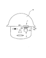
本実施形態に係る頭部装着型表示装置1は、図1に示すように、表示装置本体2と、この表示装置本体2をヘルメットHに回動可能に支持させる支持部3とを具備する。
As shown in FIG. 1, the head-mounted display device 1 according to this embodiment includes a
前記表示装置本体2は、この種の頭部装着型表示装置に用いられるものとして従来周知の構成を有する。すなわち、内部に図示しない表示器及び光学系を有する表示ユニット21と、この表示ユニット21と前記支持部3とを接続するためのベースユニット22と、これらベースユニット22と表示ユニット21とを連結し図示しないボールジョイントを利用して形成した連結部23とを具備する。
The
一方、前記支持部3は、ヘルメットHの鍔部を挟持可能なクリップ5と、このクリップ5と前記表示装置本体2のベースユニット22とを相対回転可能に支持する回転軸4とを具備する。この回転軸4は、頭部装着型表示装置1の幅方向に延伸していて、支持部3の軸中心を含む断面図を図2に示すように、内部空間41sに圧力媒体たる水を満たしているとともに弾性変形により直径を変更可能な軸本体41、この軸本体41の内部空間41sに圧力を伝達させるべく軸本体41内の水を押圧して圧力を加えるための加圧部材42、及びこの加圧部材42を進退動作させるための操作力を受け付ける操作部43を具備する。また、前記加圧部材42、及び操作部43は、前記軸本体41と一体に形成したケース44内に収納している。このケース44の内部空間は、前記軸本体41の内部空間と連通している。そして、この回転軸4は、前記クリップ5に回転不能に取り付けていて、前記ベースユニット22に設けた軸受穴22aに挿通させている。この回転軸4が、本発明の回転軸である。
On the other hand, the
具体的には、前記軸本体41は、水を内部空間41sに満たした中空円筒状の部材である。この軸本体41は、樹脂により形成していて、内部空間41sから水圧を受けて円筒面部の直径が変化する。
Specifically, the
前記加圧部材42は、前記軸本体41の内部空間41sに満たした水と隙間無く接する栓である。また、この加圧部材42の周壁には、液漏れ防止を図るべくOリング42aを配している。
The
前記操作部43は、前記加圧部材42を先端に接続してなる雄ねじ部材43aと、この雄ねじ部材43aに螺合可能な雌ねじ部材43bとを具備する。また、本実施形態では、この操作部43は前記加圧部材42と一体に形成している。さらに詳述すると、前記雄ねじ部材43aは、手回しねじを利用して形成していて、頭部43a1に回転力を加えられた際に回転力を軸力に変換する。その際、この軸力を利用して、雄ねじ部材43a及び加圧部材42を雌ねじ部材43bに対して一体的に進退させるように構成している。そして、この回転軸4は、雄ねじ部材43a及び加圧部材42の進退に伴い圧力媒体が受ける圧力すなわち水圧の変化に伴い、軸本体41の直径を拡縮するように構成している。
The
一方、前記軸受穴22aは、軸本体41に対応する部位に設けてなり、この軸本体41を略隙間無く収納する。そして、前記軸本体41の少なくとも一部を接触させた状態でこの軸本体41を保持するとともに、軸本体41の直径の変更に対応してこの軸本体41との間の摩擦力を変化させる。
On the other hand, the
次いで、本発明に係る各部の作用を以下に述べる。 Next, the operation of each part according to the present invention will be described below.
まず、雄ねじ部材43aを締着方向に回転させると、ねじの軸力が加圧部材42に加えられ、加圧部材42が軸本体41の内部空間41s側に向かって移動する。このとき、この加圧部材42を介して軸本体41の内部空間41s内の水に圧力が加えられる。さらに、加えられた圧力は軸本体41の表面全体に伝達され、軸本体41を外方に向けて押圧する。この押圧力を受けて軸本体41が弾性変形して直径が増加する。そして、この軸本体41の直径増加を受けて軸本体41と軸受穴22aとの間の摩擦力が増大する。
First, when the
逆に、雄ねじ部材43aを反締着方向に回転させると、加圧部材42が軸本体41の内部空間41s内の水から水圧を受けつつ軸本体41側から離間する方向に向かって移動する。その際、加圧部材42を介して軸本体41の内部空間41s内の水に加えられる圧力が低下し、内部空間41sの水圧も低下するので、軸本体41は自らの弾性により変形し、軸本体41の直径が減少する。そして、この軸本体41の直径減少を受けて軸本体41と軸受穴22aとの間の摩擦力も減少する。
Conversely, when the
なお、前記表示ユニット21による表示を行う際の各部の作用は、この種の頭部装着型表示装置に用いられるものとして周知のものを利用しているので、詳細な説明は省略する。 In addition, since the effect | action of each part at the time of performing the display by the said display unit 21 utilizes what is known as what is used for this kind of head mounted display apparatus, detailed description is abbreviate | omitted.
すなわち、本実施形態に係る回転軸4の構成によれば、加圧部材42により軸本体41の内部空間41sに満たした圧力媒体たる水を押圧して圧力媒体に圧力を伝達し、伝達された圧力を軸本体41の外周にさらに伝達して軸本体41を弾性変形させ、この軸本体41の直径を変更することにより、軸本体41と軸受穴22aとの間の摩擦力を変更することができる。すなわち、加圧部材42により軸本体41内の水を押圧する力を、パスカルの原理を利用して、すなわち、加圧部材42が受けた圧力と同じ圧力が軸本体41の内部空間41sに満たした水を介して軸本体41に均等に加わり、加圧部材42の水に接する部分の面積をA、軸本体41の円筒面の面積をBとした場合に前記加圧部材42が受けた力のB/A倍に増幅された押し力を軸本体41の円筒面が受けることを利用して増幅し、軸本体41の外周にさらに伝達するため、小さな操作力により軸本体41の直径を変更させるために十分大きな圧力を作り、軸本体41と軸受穴22aとの間の摩擦力を容易に変更することができる。従って、軸本体41及び軸受穴22aを形成する際に必ずしも高い加工精度を必要としないようにできる。また、軸本体41の直径を変更することにより、軸本体41と軸受穴22aとの間の摩擦力を変更し、周囲の温度に関わらず回転軸4と軸受穴22aとの間の摩擦を一定に保つ要望や、利用者ごとに回転軸4と軸受穴22aとの間の摩擦の大きさを変化させて各利用者の所望の操作感を得ることができるようにする要望に対応することができる。
That is, according to the configuration of the
また、前記操作部43が、前記加圧部材42を先端に接続してなる雄ねじ部材43aと、この雄ねじ部材43aに螺合可能な雌ねじ部材43bとを具備するので、雄ねじ部材43aと雌ねじ部材43bとを螺合させ、雄ねじ部材43aを雌ねじ部材43bに対して進退させることにより、この雄ねじ部材43aの先端に接続した加圧部材42を同時に進退させることができる。従って、より小さな操作力で加圧部材42の進退操作を行うことができるようになり、加圧部材42の進退操作を容易に行えるようにするとともに加圧部材42を任意の位置に保持できるようにすることができる。
Further, since the
さらに、水を圧力媒体として利用しているので、軸本体41の内側面の全域に均一に圧力を伝達させることができ、また、このような圧力媒体を容易かつ安価に入手できる。
Furthermore, since water is used as the pressure medium, the pressure can be transmitted uniformly over the entire inner surface of the
そして、前記軸本体41を、樹脂により形成しているので、より小さな圧力変化により軸本体41を弾性変形させ、その直径を変更できる。
And since the said shaft
なお、本発明は以上に述べた実施例に限らない。 The present invention is not limited to the embodiment described above.
例えば、圧力媒体として、水以外の液体を用いてもよく、また、ゴム等の弾性変形可能かつ圧力を伝達可能な固体やゲル等を用いてもよい。さらに、圧力媒体として気体を用いてももちろんよい。但し、圧力媒体が液体又は固体であれば加圧部材の進退幅を小さくできる。 For example, a liquid other than water may be used as the pressure medium, or a solid or gel that can be elastically deformed and can transmit pressure, such as rubber, may be used. Of course, a gas may be used as the pressure medium. However, if the pressure medium is liquid or solid, the advance / retreat width of the pressure member can be reduced.
また、ノートパソコンや携帯電話のヒンジ部等に本発明の回転軸を設け、任意の相対角度に保持可能なヒンジ機構を実現するようにしてもよい。 Further, the hinge shaft of the present invention may be provided in a hinge portion of a notebook computer or a mobile phone, and a hinge mechanism that can be held at an arbitrary relative angle may be realized.
さらに、上述した実施形態ではねじ作用により加圧部材の位置を無段階で調整できるようにしているが、加圧部材を複数箇所の係止位置のいずれかに選択的に保持可能な構成を採用してもよい。 Furthermore, in the above-described embodiment, the position of the pressure member can be adjusted steplessly by the screw action, but a configuration in which the pressure member can be selectively held at any of a plurality of locking positions is adopted. May be.
加えて、上述した実施形態では回転軸をクリップに回転不能に取り付け、表示装置本体に形成した軸受穴に挿通させるようにしているが、回転軸を表示装置本体と一体的に回転可能に構成し、クリップに設けた軸受穴に挿通させるようにしてももちろんよい。 In addition, in the above-described embodiment, the rotation shaft is attached to the clip so as not to rotate, and is inserted into the bearing hole formed in the display device body. However, the rotation shaft is configured to be rotatable integrally with the display device body. Of course, it may be inserted through a bearing hole provided in the clip.
そして、軸本体は、樹脂により形成したものに限らず、硬質ゴムや弾性を有する金属等により、弾性変形可能かつ内部に圧力媒体を満たすことが可能な筒状に形成したものであっても、本発明の最も重要な効果、すなわち軸受との摩擦力を調整可能にできる効果は得られる。 And the shaft main body is not limited to the one formed of resin, even if it is formed in a cylindrical shape that can be elastically deformed and can fill the pressure medium with hard rubber or elastic metal, etc. The most important effect of the present invention, that is, an effect capable of adjusting the frictional force with the bearing can be obtained.
その他、各部の具体的構成についても上記実施形態に限られるものではなく、本発明の趣旨を逸脱しない範囲で種々変形が可能である。 In addition, the specific configuration of each part is not limited to the above embodiment, and various modifications can be made without departing from the spirit of the present invention.
1…頭部装着型表示装置
2…表示装置本体
22a…軸受穴
3…支持部
4…回転軸
41…軸本体
42…加圧部材
43…操作部
43a…雄ねじ部材
43b…雌ねじ部材
DESCRIPTION OF SYMBOLS 1 ... Head-mounted
Claims (7)
Priority Applications (1)
| Application Number | Priority Date | Filing Date | Title |
|---|---|---|---|
| JP2008174178A JP5151741B2 (en) | 2008-07-03 | 2008-07-03 | Rotating shaft and head-mounted display device |
Applications Claiming Priority (1)
| Application Number | Priority Date | Filing Date | Title |
|---|---|---|---|
| JP2008174178A JP5151741B2 (en) | 2008-07-03 | 2008-07-03 | Rotating shaft and head-mounted display device |
Publications (2)
| Publication Number | Publication Date |
|---|---|
| JP2010014185A true JP2010014185A (en) | 2010-01-21 |
| JP5151741B2 JP5151741B2 (en) | 2013-02-27 |
Family
ID=41700472
Family Applications (1)
| Application Number | Title | Priority Date | Filing Date |
|---|---|---|---|
| JP2008174178A Expired - Fee Related JP5151741B2 (en) | 2008-07-03 | 2008-07-03 | Rotating shaft and head-mounted display device |
Country Status (1)
| Country | Link |
|---|---|
| JP (1) | JP5151741B2 (en) |
Citations (4)
| Publication number | Priority date | Publication date | Assignee | Title |
|---|---|---|---|---|
| JPH08132136A (en) * | 1994-11-10 | 1996-05-28 | Sumitomo Metal Ind Ltd | Equipment for coiling strip-shaped product |
| JPH11142782A (en) * | 1997-11-11 | 1999-05-28 | Seiko Epson Corp | Head mount type display device |
| JP2001225999A (en) * | 2000-02-18 | 2001-08-21 | Shin Nippon Kasei Kk | Sheet winding device |
| JP2007205538A (en) * | 2006-02-06 | 2007-08-16 | Shimonishi Giken Kogyo Kk | Tilt hinge |
-
2008
- 2008-07-03 JP JP2008174178A patent/JP5151741B2/en not_active Expired - Fee Related
Patent Citations (4)
| Publication number | Priority date | Publication date | Assignee | Title |
|---|---|---|---|---|
| JPH08132136A (en) * | 1994-11-10 | 1996-05-28 | Sumitomo Metal Ind Ltd | Equipment for coiling strip-shaped product |
| JPH11142782A (en) * | 1997-11-11 | 1999-05-28 | Seiko Epson Corp | Head mount type display device |
| JP2001225999A (en) * | 2000-02-18 | 2001-08-21 | Shin Nippon Kasei Kk | Sheet winding device |
| JP2007205538A (en) * | 2006-02-06 | 2007-08-16 | Shimonishi Giken Kogyo Kk | Tilt hinge |
Also Published As
| Publication number | Publication date |
|---|---|
| JP5151741B2 (en) | 2013-02-27 |
Similar Documents
| Publication | Publication Date | Title |
|---|---|---|
| US9329636B2 (en) | Information processing method and electronic device | |
| WO2009054291A1 (en) | Mechanical pencil | |
| JP5973059B2 (en) | Hinge device | |
| CN102137738A (en) | Torque wrench | |
| JP2009183987A (en) | Friction welding device | |
| WO2003036111A1 (en) | Bearing unit, and motor using this bearing unit | |
| JP2007301149A (en) | Medical handpiece | |
| WO2005124192A3 (en) | Compact actuator | |
| JP2005325944A (en) | Lead screw type moving device and its moving body | |
| JP2008003032A (en) | Digital displacement measuring instrument | |
| JP2005254880A (en) | Rack guide for rack pinion type steering device | |
| JP5151741B2 (en) | Rotating shaft and head-mounted display device | |
| AU2003286132A1 (en) | Disk brake | |
| WO2004011302A3 (en) | Friction hinge assembly for a mirror of a display unit | |
| JP2007198425A (en) | Preloading device and preloading method for rolling bearing, and bearing unit | |
| TW200712836A (en) | Notebook computer capable of adjusting a screen via a telescopic element | |
| JP2007067774A (en) | Hinge mechanism of rod antenna | |
| JP2009079696A (en) | Mechanism for applying preload to rolling bearing | |
| JP6125214B2 (en) | Cutting pen | |
| ES1051839U (en) | Articulated support arm awning with spring load. (Machine-translation by Google Translate, not legally binding) | |
| JP2004140939A (en) | Multiple latitude driver | |
| JP2007205538A (en) | Tilt hinge | |
| FR2892163B1 (en) | OBLIQUE CONTACT BEARING, CORRESPONDING MODULE AND STEERING COLUMN. | |
| JP2005245623A (en) | Feeder device of stick cosmetic | |
| CN216634464U (en) | Linear rotation device and robot |
Legal Events
| Date | Code | Title | Description |
|---|---|---|---|
| A621 | Written request for application examination |
Free format text: JAPANESE INTERMEDIATE CODE: A621 Effective date: 20100907 |
|
| A131 | Notification of reasons for refusal |
Free format text: JAPANESE INTERMEDIATE CODE: A131 Effective date: 20111227 |
|
| A977 | Report on retrieval |
Free format text: JAPANESE INTERMEDIATE CODE: A971007 Effective date: 20111227 |
|
| A521 | Written amendment |
Free format text: JAPANESE INTERMEDIATE CODE: A523 Effective date: 20120213 |
|
| A02 | Decision of refusal |
Free format text: JAPANESE INTERMEDIATE CODE: A02 Effective date: 20120710 |
|
| A521 | Written amendment |
Free format text: JAPANESE INTERMEDIATE CODE: A523 Effective date: 20120906 |
|
| A911 | Transfer of reconsideration by examiner before appeal (zenchi) |
Free format text: JAPANESE INTERMEDIATE CODE: A911 Effective date: 20120914 |
|
| TRDD | Decision of grant or rejection written | ||
| A01 | Written decision to grant a patent or to grant a registration (utility model) |
Free format text: JAPANESE INTERMEDIATE CODE: A01 Effective date: 20121106 |
|
| A61 | First payment of annual fees (during grant procedure) |
Free format text: JAPANESE INTERMEDIATE CODE: A61 Effective date: 20121119 |
|
| FPAY | Renewal fee payment (event date is renewal date of database) |
Free format text: PAYMENT UNTIL: 20151214 Year of fee payment: 3 |
|
| FPAY | Renewal fee payment (event date is renewal date of database) |
Free format text: PAYMENT UNTIL: 20151214 Year of fee payment: 3 |
|
| LAPS | Cancellation because of no payment of annual fees |