JP2010013845A - Method and structure for installing anchor plate - Google Patents
Method and structure for installing anchor plate Download PDFInfo
- Publication number
- JP2010013845A JP2010013845A JP2008174414A JP2008174414A JP2010013845A JP 2010013845 A JP2010013845 A JP 2010013845A JP 2008174414 A JP2008174414 A JP 2008174414A JP 2008174414 A JP2008174414 A JP 2008174414A JP 2010013845 A JP2010013845 A JP 2010013845A
- Authority
- JP
- Japan
- Prior art keywords
- anchor
- ground
- anchor plate
- insertion hole
- slope
- Prior art date
- Legal status (The legal status is an assumption and is not a legal conclusion. Google has not performed a legal analysis and makes no representation as to the accuracy of the status listed.)
- Granted
Links
- 238000000034 method Methods 0.000 title claims abstract description 23
- 238000003780 insertion Methods 0.000 claims abstract description 26
- 230000037431 insertion Effects 0.000 claims abstract description 26
- 239000011440 grout Substances 0.000 claims abstract description 13
- 238000005553 drilling Methods 0.000 claims abstract description 11
- 230000002787 reinforcement Effects 0.000 claims abstract description 9
- 239000011435 rock Substances 0.000 claims abstract description 5
- 238000009434 installation Methods 0.000 claims description 40
- 230000003014 reinforcing effect Effects 0.000 claims description 32
- 239000002689 soil Substances 0.000 claims description 14
- 239000000945 filler Substances 0.000 claims description 13
- 244000025254 Cannabis sativa Species 0.000 claims description 5
- 238000004873 anchoring Methods 0.000 claims description 5
- 238000010276 construction Methods 0.000 claims description 4
- 229910000831 Steel Inorganic materials 0.000 description 10
- 239000010959 steel Substances 0.000 description 10
- 239000000463 material Substances 0.000 description 8
- 210000002435 tendon Anatomy 0.000 description 7
- 239000006185 dispersion Substances 0.000 description 3
- 230000001154 acute effect Effects 0.000 description 2
- 238000006243 chemical reaction Methods 0.000 description 2
- 239000004567 concrete Substances 0.000 description 2
- 239000000835 fiber Substances 0.000 description 2
- 238000002347 injection Methods 0.000 description 2
- 239000007924 injection Substances 0.000 description 2
- 230000001681 protective effect Effects 0.000 description 2
- 230000000087 stabilizing effect Effects 0.000 description 2
- XLYOFNOQVPJJNP-UHFFFAOYSA-N water Substances O XLYOFNOQVPJJNP-UHFFFAOYSA-N 0.000 description 2
- 230000009471 action Effects 0.000 description 1
- 230000008901 benefit Effects 0.000 description 1
- 230000015572 biosynthetic process Effects 0.000 description 1
- 239000004568 cement Substances 0.000 description 1
- 239000002131 composite material Substances 0.000 description 1
- 230000006835 compression Effects 0.000 description 1
- 238000007906 compression Methods 0.000 description 1
- GUJOJGAPFQRJSV-UHFFFAOYSA-N dialuminum;dioxosilane;oxygen(2-);hydrate Chemical compound O.[O-2].[O-2].[O-2].[Al+3].[Al+3].O=[Si]=O.O=[Si]=O.O=[Si]=O.O=[Si]=O GUJOJGAPFQRJSV-UHFFFAOYSA-N 0.000 description 1
- 238000006073 displacement reaction Methods 0.000 description 1
- 230000000694 effects Effects 0.000 description 1
- 238000005516 engineering process Methods 0.000 description 1
- 230000001771 impaired effect Effects 0.000 description 1
- 230000007246 mechanism Effects 0.000 description 1
- 230000004048 modification Effects 0.000 description 1
- 238000012986 modification Methods 0.000 description 1
- 230000002093 peripheral effect Effects 0.000 description 1
- 230000002265 prevention Effects 0.000 description 1
- 230000008569 process Effects 0.000 description 1
- 239000012779 reinforcing material Substances 0.000 description 1
- 239000004576 sand Substances 0.000 description 1
- 239000007787 solid Substances 0.000 description 1
- 238000007711 solidification Methods 0.000 description 1
- 230000008023 solidification Effects 0.000 description 1
- 230000006641 stabilisation Effects 0.000 description 1
- 238000011105 stabilization Methods 0.000 description 1
Images

Landscapes
- Piles And Underground Anchors (AREA)
- Pit Excavations, Shoring, Fill Or Stabilisation Of Slopes (AREA)
Abstract
Description
本発明は、グラウンドアンカー工に用いるアンカープレートの定着構造に係り、特に、比較的小さい削孔に高強度の鋼材などの引張り材を挿入し、これを基盤内に定着させて、鋼材の引張り強さを利用することにより地すべり対策工としているグラウンドアンカー工に用いるアンカープレートの設置方法、及びアンカープレートの設置構造に関する。 The present invention relates to a fixing structure of an anchor plate used for ground anchor work, and in particular, a tensile material such as a high-strength steel material is inserted into a relatively small drilling hole, and this is fixed in a base, whereby the tensile strength of the steel material is increased. It is related with the installation method of the anchor plate used for the ground anchor work used as a landslide countermeasure work, and the installation structure of the anchor plate.
従来より、山間地、あるいは工場敷地の造成地における斜面や、崩落又は崩壊のおそれのある法面の保護工として、また仮設又は本設土留壁の土留支保工としてグラウンドアンカー工が用いられている。 Conventionally, ground anchors have been used as protective works for slopes in mountainous areas or planted land, slopes that may collapse or collapse, and as retaining works for temporary or permanent retaining walls. .
グラウンドアンカーは、一般に「定着部」、「引張り部」、及び「アンカー頭部」から構成される。定着部は、グラウトの注入により造成され、引張り部からの引張り力を地盤との摩擦抵抗もしくは支圧抵抗によって地盤に伝達するための抵抗部分であり、定着部は通常、PC鋼棒、PC鋼より線、多重PC鋼より線、連続繊維補強材などを材料としたテンドン、及びセメント系のグラウトによって構成される。引張り部は、アンカー頭部からの引張り力を定着部に伝達する部分であり、テンドン、及び伸び量を均一にするためのシースで構成される。アンカー頭部は、テンドンに発生している引張り力を、構造物へ確実に伝達させる機能を持つ。アンカー頭部はテンドンを締め付け、かつ固定するために用いるくさび、ナットなどの定着具、定着具による大きな支圧荷重を分散させるための鋼製の支圧板などによって構成される。 The ground anchor is generally composed of a “fixing portion”, a “pull portion”, and an “anchor head portion”. The fixing part is formed by injecting grout, and is a resistance part for transmitting the tensile force from the tension part to the ground by frictional resistance or bearing resistance with the ground. The fixing part is usually a PC steel bar or PC steel. It is composed of stranded wire, multi-PC steel strand, tendon made of continuous fiber reinforcement, etc., and cement grout. The tension portion is a portion that transmits a tensile force from the anchor head to the fixing portion, and is composed of a tendon and a sheath for making the amount of elongation uniform. The anchor head has a function of reliably transmitting the tensile force generated in the tendon to the structure. The anchor head is composed of a wedge used for fastening and fixing the tendon, a fixing tool such as a nut, and a steel bearing plate for dispersing a large bearing load by the fixing tool.
グラウンドアンカーは、定着部と定着地盤との定着方式により3つの定着機構に大別できる。すなわち、定着部周面と定着地盤との摩擦抵抗によりアンカー引抜力を定着地盤に伝達する摩擦型アンカー、定着部を大きく拡孔し定着部に作用する受働土圧にてアンカー引抜力に抵抗する支圧型アンカー、上記摩擦型と支圧型を併用した複合型アンカーなどである。 Ground anchors can be roughly divided into three fixing mechanisms depending on the fixing method of the fixing portion and the fixing ground. That is, a friction type anchor that transmits anchor pulling force to the fixing ground by frictional resistance between the peripheral surface of the fixing unit and the fixing ground, and resists anchor pulling force by a passive earth pressure that greatly expands the fixing unit and acts on the fixing unit. A bearing anchor, a composite anchor using both the friction type and the bearing type.
地すべり対策工としてのグラウンドアンカー工は、以下の二つの抑止機能を持つと考えられているが、地盤、及びすべり面の状況によって、どちらか一方の機能を重視して設計される場合がある。また、適する地盤条件はそれぞれ以下の通りである。 The ground anchor work as a landslide countermeasure work is considered to have the following two deterrence functions, but may be designed with emphasis on one of the functions depending on the ground and slip surface conditions. The appropriate ground conditions are as follows.
(a)締め付け機能:すべり面での垂直応力を増加させ、せん断抵抗力を増大させる。
・すべり面が比較的浅い、急斜面
・すべり土塊の強度が大きい
・岩盤すべり
(b)引止め機能:すべり力の反力としてグラウンドアンカーの引張り力を用いる。
・すべり面が比較的深い
・すべり面の勾配が緩勾配
・すべり土塊の強度が小さい
(A) Tightening function: Increases the vertical stress on the sliding surface and increases the shear resistance.
・ Slip surface is relatively shallow, steep slope ・ Slide mass is large ・ Brock slip (b) Retaining function: The tensile force of the ground anchor is used as the reaction force of the slip force.
・ Slip surface is relatively deep ・ Slip surface slope is gentle ・ Slide mass is low
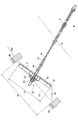
図5は、従来のアンカープレートの設置構造について示している。グラウンドアンカー90の定着部Bは、想定すべり線Sの下部の岩盤Rに固着されており、引張り部91は、アンカー頭部93が法面120に設置されているアンカープレート94に支圧板92を介して係合され、所定の引張力となるように設定されている。
FIG. 5 shows a conventional anchor plate installation structure. The anchoring portion B of the
斜面や法面は地震などの場合に想定すべり線Sに沿って流動することが想定されるため、グラウンドアンカー90は、そのすべり力101の反力102を確保するため、グラウンドアンカー90の引張力により、常時斜面や法面に必要な圧迫力を与えておくものである。ここで、斜面や法面の保護工において、グラウンドアンカー90を多数利用するが、同じ施工地に用いる各グラウンドアンカー90は、施工地全体を考慮して全体として最適な角度に設定される設置角度(水平面Lに対する角度θ)で、相互間の干渉を避けるため、お互いに全て平行に設置される。ここで、特に、斜面や法面が緩やかな斜面でありながら、その斜面や法面の下に重要設備がある、斜面直近に民家がある、あるいは斜面の土質が軟弱である、などの理由で、その緩やかな斜面や法面に安全対策上グラウンドアンカー90を設置するとき発生し易いことであるが、法面120の傾斜とグラウンドアンカー90の位置関係から、そこに設置されたアンカープレート94と引張り部91のなす角αが鋭角になる場合がある。この場合、引張り部91の引張力の分力の作用により、アンカープレート94に対して法面120に沿った上向きの横力103が発生し、アンカープレート94が所定の位置から法面120に沿って数mmから数10mm上方に移動する可能性があるという問題がある。アンカープレート94が所定の位置から移動すると、強い引張力の架かっている引張り部91も所定の位置からずれるという問題がある。
Since slopes and slopes are assumed to flow along an assumed slip line S in the case of an earthquake or the like, the
これらの問題について、法面を安定化するためのアンカープレートにおいて、アンカープレートをアンカーと直交させて設置すべくアンカープレートと地盤面との間にテーパー状断面の増設部を配置する技術(特許文献1参照)が開示されており、また、格子状の法枠におけるアンカー材の設置位置に関する技術(特許文献2参照)が開示されているが、アンカープレートのアンカー引張力による位置ずれの防止に関するもの、アンカープレートと法枠との関係に関するものは見当たらない。
本発明は、以上のような問題点を解決し、アンカープレートの移動を防止し、有効な法面保護を行うことができるアンカープレートの設置方法、及びアンカープレートの設置構造を提供することを目的とする。 An object of the present invention is to solve the above problems, to provide an anchor plate installation method and an anchor plate installation structure capable of preventing the movement of the anchor plate and performing effective slope protection. And
上記の課題を解決するため、本発明者は、アンカープレートを設置する地表面を補強枠で囲むと共にグラウンドアンカーとほぼ直角になるように整地してアンカープレートを設置することによりアンカープレートを安定化できることを見出し、本発明を完成するに至った。 In order to solve the above problems, the present inventor has stabilized the anchor plate by surrounding the ground surface on which the anchor plate is to be installed with a reinforcing frame and leveling the ground plate so as to be substantially perpendicular to the ground anchor. The present inventors have found that this can be done and have completed the present invention.
(1) 法面に平面略格子状の補強枠を構築する工程と、前記補強枠で囲まれた内部地表面のほぼ中央に開口すると共に、一定長のアンカー挿通孔を削孔する工程と、前記アンカー挿通孔にグラウンドアンカーを挿入すると共に、グラウトを注入し前記グラウンドアンカーの定着部を岩盤に固着する工程と、前記内部地表面に、前記アンカー挿通孔を中心に所定の範囲にわたり、かつ前記グラウンドアンカーとほぼ直角となる整地面を形成する工程と、前記整地面にアンカープレートを設置し、前記グラウンドアンカーの前記アンカー挿通孔から突出するアンカー頭部を前記アンカープレートの中心に接続する工程と、前記グラウンドアンカーに所定の引張り力を印加する工程と、を含むアンカープレートの設置方法。 (1) a step of constructing a plane substantially lattice-like reinforcing frame on the slope, a step of opening an approximately center of the inner ground surface surrounded by the reinforcing frame, and drilling a fixed length anchor insertion hole, Inserting a ground anchor into the anchor insertion hole, injecting a grout and fixing the anchoring portion of the ground anchor to a rock, and a predetermined range around the anchor insertion hole on the inner ground surface; and Forming a ground surface that is substantially perpendicular to the ground anchor; installing an anchor plate on the ground surface; and connecting an anchor head protruding from the anchor insertion hole of the ground anchor to the center of the anchor plate; Applying a predetermined tensile force to the ground anchor, and an anchor plate installation method.
(1)の発明におけるアンカープレートの設置方法によれば、補強枠格子の内部地表面をグラウンドアンカーとほぼ直角になるような整地面を形成することにより、アンカープレートに引張力を印加してもアンカープレートのずれを防ぐことができる。また、元の内部地表面から大きく変更して整地面を形成した場合であっても補強枠の内部であるため、整地面が受止めた押圧力の横方向への分散力を補強枠が受止めることができるので、整地面は安定しており、そこに設置されているアンカープレートは安定的に整地面を押圧することができる。 According to the anchor plate installation method in the invention of (1), even if a tensile force is applied to the anchor plate by forming the ground surface so that the inner ground surface of the reinforcing frame lattice is substantially perpendicular to the ground anchor. The anchor plate can be prevented from shifting. In addition, even if the ground leveling surface is formed by largely changing from the original inner ground surface, the reinforcing frame receives the dispersion force in the lateral direction of the pressing force received by the leveling ground because it is inside the reinforcing frame. Since it can stop, the leveling ground is stable, and the anchor plate installed there can stably press the leveling ground.
(2) (1)に記載のアンカープレートの設置方法において、前記整地面を形成する工程は、前記内部地表面を実質的に掘削して行うアンカープレートの設置方法。 (2) In the anchor plate installation method according to (1), the step of forming the leveling surface is an anchor plate installation method which is performed by substantially excavating the inner ground surface.
(3) (1)に記載のアンカープレートの設置方法において、前記整地面を形成する工程は、前記内部地表面の法面傾斜方向下側を実質的に掘削して、前記内部地表面の法面傾斜方向上側を実質的に盛土して行うアンカープレートの設置方法。 (3) In the anchor plate installation method according to (1), the step of forming the leveling surface includes substantially excavating a lower side in the slope direction of the inner ground surface, thereby correcting the inner ground surface. An anchor plate installation method that is performed by substantially embedding the upper side of the surface inclination direction.
(2)及び(3)の発明におけるアンカープレートの設置方法は、施工しようとする法面の状況に応じて適宜使い分けることができる。特に、(3)の発明におけるアンカープレートの設置方法によれば、補強枠で囲まれた内部地表面の法面下側を実質的に掘削して、法面上側を実質的に盛土するため、補強枠の格子内部で土が再利用でき、外部への土の搬出が不要になる、もしくは少なくなる。 The installation method of the anchor plate in the inventions of (2) and (3) can be properly used according to the situation of the slope to be constructed. In particular, according to the anchor plate installation method in the invention of (3), substantially excavating the slope lower side of the inner ground surface surrounded by the reinforcing frame, and substantially embanking the slope upper side, The soil can be reused inside the grid of the reinforcing frame, and it is unnecessary or less necessary to carry out the soil to the outside.
(4)(1)に記載のアンカープレートの設置方法において、前記整地面にアンカープレートを設置するとき前記アンカープレートと前記整地面の間に固化性充填剤を充填し、前記固化性充填剤が固化してから、前記グラウンドアンカーに所定の引張り力を印加する工程を行うアンカープレートの設置方法。 (4) In the anchor plate installation method according to (1), when the anchor plate is installed on the leveling surface, a solidifying filler is filled between the anchor plate and the leveling surface, and the solidifying filler is An anchor plate installation method for performing a step of applying a predetermined tensile force to the ground anchor after solidification.
(4)の発明におけるアンカープレートの設置方法によれば、固化性充填剤が固化した後は、固化性充填剤がアンカープレートと整地面との両者に密着し、アンカープレートに加わる圧力を整地面に均等に伝達するようになるため、整地面は更に安定しており、そこに設置されているアンカープレートは安定的に整地面を押圧することができる。 According to the anchor plate installation method in the invention of (4), after the solidifying filler is solidified, the solidifying filler is brought into close contact with both the anchor plate and the leveling surface, and the pressure applied to the anchor plate is adjusted. Therefore, the leveling surface is more stable, and the anchor plate installed there can stably press the leveling surface.
(5) 法面に構築された平面略格子状の補強枠と、前記補強枠で囲まれる内部地表面のほぼ中央に開口するアンカー挿通孔と、前記アンカー挿通孔からアンカー頭部が突出すると共に定着部が地盤に固着されたグラウンドアンカーと、前記内部地表面に、前記アンカー挿通孔を中心に所定の範囲にわたり、かつ前記グラウンドアンカーとほぼ直角となるよう形成された整地面と、前記整地面に設置されたアンカープレートと、を備え、前記グラウンドアンカーは、所定の引張力を印加されると共に前記アンカー頭部が前記アンカープレートの中心に接続されたアンカープレートの設置構造。 (5) A planar substantially lattice-shaped reinforcing frame constructed on the slope, an anchor insertion hole that opens to substantially the center of the inner ground surface surrounded by the reinforcing frame, and an anchor head projecting from the anchor insertion hole A ground anchor having a fixing portion fixed to the ground; a ground surface formed on the inner ground surface so as to extend over a predetermined range around the anchor insertion hole and substantially perpendicular to the ground anchor; and the ground surface An anchor plate installed on the ground plate, wherein the ground anchor is applied with a predetermined tensile force, and the anchor head is connected to the center of the anchor plate.
(5)の発明におけるアンカープレートの設置構造によれば、補強枠の格子内部の地表面をグラウンドアンカーとほぼ直角になるような整地面を形成することにより、アンカープレートに引張力を印加してもアンカープレートのずれを防ぐことができる。また、元の内部地表面から大きく変更して整地面を形成した場合であっても補強枠の内部であるため、整地面が受止めた押圧力の横方向への分散力を補強枠が受止めることができるので、整地面が安定している。 According to the anchor plate installation structure in the invention of (5), a tensile force is applied to the anchor plate by forming a ground leveling surface so that the ground surface inside the lattice of the reinforcing frame is substantially perpendicular to the ground anchor. Can also prevent the displacement of the anchor plate. In addition, even if the ground leveling surface is formed by largely changing from the original inner ground surface, the reinforcing frame receives the dispersion force in the lateral direction of the pressing force received by the leveling ground because it is inside the reinforcing frame. Since it can be stopped, the leveling surface is stable.
(6) 前記アンカープレートと前記整地面の間に固化した固化性充填剤層を更に備える、(5)に記載のアンカープレートの設置構造。 (6) The anchor plate installation structure according to (5), further including a solidifying filler layer solidified between the anchor plate and the leveling surface.
(6)の発明におけるアンカープレートの設置構造によれば、固化した固化性充填剤がアンカープレートと整地面との両者に密着し、アンカープレートに加わる圧力を整地面に均等に伝達するようになるため、整地面は更に安定しており、そこに設置されているアンカープレートは安定的に整地面を押圧することができる。 According to the installation structure of the anchor plate in the invention of (6), the solidified solidifying filler is in close contact with both the anchor plate and the leveling surface, and the pressure applied to the anchor plate is uniformly transmitted to the leveling surface. Therefore, the leveling surface is further stable, and the anchor plate installed therein can stably press the leveling surface.
(7) (5)に記載のアンカープレートの設置構造において、前記アンカープレートの法面傾斜方向の長さは、前記補強枠の法面傾斜方向の間隔の50%以上であるアンカープレートの設置構造。 (7) The anchor plate installation structure according to (5), wherein a length of the anchor plate in the normal direction is 50% or more of an interval in the normal direction of the reinforcement frame. .
(7)の発明のアンカープレートの設置構造によれば、アンカープレートの法面傾斜方向の長さが補強枠の法面傾斜方向の間隔の50%以上であるため、補強枠は押圧力が印加されている整地面に十分近く、補強枠による整地面の安定化効果は更に大きい。 According to the anchor plate installation structure of the invention of (7), since the length of the anchor plate in the slope direction of the anchor plate is 50% or more of the interval in the slope direction of the reinforcement frame, a pressing force is applied to the reinforcement frame. It is close enough to the ground leveling that is done, and the stabilizing effect of the leveling ground by the reinforcing frame is even greater.
(8) (5)から(7)のいずれかに記載のアンカープレートの設置構造において、前記内部地表面であって前記アンカープレートで覆われていない部分は、土壌が草本類の植生が可能であるアンカープレートの設置構造。 (8) In the anchor plate installation structure according to any one of (5) to (7), the portion of the inner ground surface that is not covered with the anchor plate can be herbaceous vegetation. An anchor plate installation structure.
(9) (8)に記載のアンカープレートの設置構造において、前記アンカープレートの上面を草本類の植生が可能な土壌で覆うアンカープレートの設置構造。 (9) The anchor plate installation structure according to (8), wherein an upper surface of the anchor plate is covered with soil capable of herbaceous vegetation.
(8)の発明のアンカープレートの設置構造によれば、アンカープレートの周囲の表土面に、草、芝生を生やすことができ、人工構造物であるアンカープレートが隠されて目立たなくさせることができる。また、(9)の発明のアンカープレートの設置構造によれば、アンカープレートの上面を土で覆い隠せばアンカープレートの上の土壌にも草本類の植生が可能になり、緑化が促進され景観保全が更に高められる。 According to the anchor plate installation structure of the invention of (8), grass and lawn can be grown on the topsoil surface around the anchor plate, and the anchor plate which is an artificial structure can be hidden and made inconspicuous. . Further, according to the anchor plate installation structure of the invention of (9), if the upper surface of the anchor plate is covered with soil, grass can be vegetated on the soil above the anchor plate, and greening is promoted and landscape conservation is achieved. Is further enhanced.
本発明によれば、アンカープレートの移動を防止し、有効な法面保護を行うことができる法枠アンカープレートの定着構造を提供することができる。 ADVANTAGE OF THE INVENTION According to this invention, the fixing structure of the frame frame anchor plate which can prevent the movement of an anchor plate and can perform effective slope protection can be provided.
以下、本発明を実施するための最良の形態について添付した図面を参照しながら説明する。なお、これはあくまでも一例であって、本発明の技術的範囲はこれに限られるものではない。 The best mode for carrying out the present invention will be described below with reference to the accompanying drawings. This is merely an example, and the technical scope of the present invention is not limited to this.
[第1の実施例]
図1は、アンカープレートの定着構造10の構成を示す断面図である。グラウンドアンカーを施工する法面120にコンクリート製の平面略格子状の補強枠99が設置され、補強枠99のほぼ中央にアンカー挿通孔95が開口している。ここで、グラウンドアンカー工のアンカー挿通孔95の削孔工程以降の工程は以下の通りである。
[First embodiment]
FIG. 1 is a cross-sectional view showing a configuration of an anchor
(1)アンカー挿通孔95の削孔
所定の位置に、ドリルパイプ(図示しない)により、設定した削孔径、削孔長、アンカー傾角、アンカー水平角になるようにグラウンドアンカーの削孔を行う。削孔終了後、周囲の地盤を乱すことがないように、削孔内を清水にて洗浄する。
(2)グラウト注入
アンカー挿通孔95に底部までグラウトホース(図示しない)を挿入し、グラウトホースよりグラウト材を注入し、削孔内の削孔水をグラウト材と完全に置き換えると共にグラウト材充填を行う。
(3)テンドン(図示しない)の挿入
テンドンは、前述の通り、通常、PC鋼棒、PC鋼より線、多重PC鋼より線、連続繊維補強材などを材料としている。
(4)グラウト材の加圧注入
(5)引張り力印加
グラウトが固まり所定の強度に達した後に、ジャッキ(図示しない)により計画した定着時緊張力で定着する。
(1) Drilling the
(2) Grout injection Insert a grout hose (not shown) into the
(3) Insertion of tendon (not shown) As described above, tendon is usually made of a PC steel rod, a PC steel wire, a multiplex PC steel wire, a continuous fiber reinforcing material, or the like.
(4) Pressure injection of grout material (5) Application of tensile force After the grout has solidified and has reached a predetermined strength, it is fixed with a tension force planned by a jack (not shown).
この工程によって、定着部Bは、想定すべり線Sの下部の岩盤Rに固着されており、鋼線よりなるグラウンドアンカー90は、アンカー頭部23がアンカー挿通孔95より内部地表面に突出している。補強枠99の内部地表面121には、法面傾斜方向下側部分を大きく掘削することにより、グラウンドアンカー90にほぼ直角な整地面20が形成されている。整地面20にアンカープレート21を設置すると共に、アンカー挿通孔95より内部地表面に突出しているアンカー頭部23は、アンカープレート21に支圧板22を介して係合される。グラウンドアンカー90は、ジャッキ(図示せず)により、所定の張力となるように引張り力を印加される。
By this process, the fixing part B is fixed to the rock mass R below the assumed slip line S, and the
ここで、施工地全体の状況により水平面に対する設置角度が定められるグラウンドアンカー90と内部地表面121がなす角が鋭角である場合であっても、アンカープレート21はグラウンドアンカー90とほぼ直角な整地面20に面して設置されているので、アンカープレート21には横力が加わらず、移動することがない。
Here, even when the angle formed by the
また、整地面20は、長期間のアンカープレート21の圧縮に耐えるようにその表面は多数の小石などを圧縮して固めておいてもよい。
Further, the surface of the leveling surface 20 may be compressed and hardened by compressing a large number of pebbles or the like so as to withstand the compression of the
また、整地面20にアンカープレート21を設置するときアンカープレート21と整地面の間に固化性充填剤27を充填し、固化性充填剤27が固化してから、グラウンドアンカー90に所定の引張り力を印加してもよい。この場合、固化した固化性充填剤27がアンカープレート21と整地面20との両者に密着し、アンカープレート21に加わる圧力を整地面20に均等に伝達するようになるため、整地面20は更に安定しており、そこに設置されているアンカープレート21は更に安定して整地面20を押圧することができる。
Further, when the
また、アンカープレート21の法面傾斜方向の長さ25は、補強枠99の法面傾斜方向の間隔26の50%以上にすると特に望ましい。この場合、アンカープレート21の法面傾斜方向の長さ25が補強枠99の法面傾斜方向の間隔26の50%以上であるため、補強枠99は押圧力が印加されている整地面20に十分近く、整地面20が受止めた押圧力の横方向への分散力を補強枠99が効果的に受止めることができて、補強枠99による整地面20の安定化効果は更に大きい。
The
[第2の実施例]
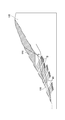
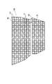
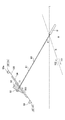
図2は、広い領域にグラウンドアンカーを多数設置する場合の概要を示す地山の法面断面図である。図3は、広い領域に補強枠を用いてグランドアンカーを多数設置する場合の概要を示す法面正面図である。図4は、アンカープレートの定着構造10Aの構成、特に、グラウンドアンカーを法面傾斜方向に、複数個を密接して配置する場合の構成を示す、図3におけるA−A視の断面図である。
[Second Embodiment]
FIG. 2 is a slope cross-sectional view of a natural ground showing an outline when a large number of ground anchors are installed in a wide area. FIG. 3 is a slope front view showing an outline when a large number of ground anchors are installed in a wide area using reinforcing frames. 4 is a cross-sectional view taken along line AA in FIG. 3 showing the configuration of the anchor
図2は、斜面や法面の保護工として、広い領域にグラウンドアンカー90を多数施工する場合の概要を示している。地山100は、その上方部分110の土砂を除去して造成され、2段斜面になっているが、下方部分の法面120は緩斜面であっても斜面下に重要設備を予定している、斜面直近に民家がある、土質が軟弱である、などの理由で安全対策上、法面120に多数のグラウンドアンカー90を設置することを必要とする場合がある。グラウンドアンカー90の定着部Bは、想定すべり線Sより深部の不動層で堅固な岩盤に定着する必要があり、また定着長は原則として3m以上、10m以下とされる。グラウンドアンカー90の設置位置、アンカー力、間隔、及び設置角度は、施工する法面120の全体を見て、全体最適になるように決定され、定着地盤の強度やすべり面深度をもとに、アンカー径、アンカー長、テンドン諸元が決定される。また、各グラウンドアンカー90は同一の設置角度で、お互いに全て平行に設置される。
FIG. 2 shows an outline in the case where a large number of ground anchors 90 are constructed in a wide area as a protective work for slopes and slopes. The
図3は、広い領域に補強枠を用いてグランドアンカーを多数設置する場合の概要を示す法面正面図である。コンクリート製の平面略格子状の補強枠99が法面120の広い範囲にわたって設置され、丸印は補強枠99の中に設置されたアンカープレート21(グランドアンカー)を示している。
FIG. 3 is a slope front view showing an outline when a large number of ground anchors are installed in a wide area using reinforcing frames. A concrete plane substantially lattice-shaped reinforcing
図4は、アンカープレートの定着構造10Aの構成、特に、グラウンドアンカーを法面傾斜方向に、複数個を密接して配置する場合の構成を示す。この実施例においては、補強枠99、99a、99b、99cの間にそれぞれ整地面20a、20b、20c、及びアンカープレート21a、21b、21cなどが配置されているが、一つの補強枠間の構成は、いずれも第1の実施例の通りである。この実施例では、整地面20a、20b、20cの形成に関して、補強枠で囲まれた内部地表面の法面傾斜方向下側を実質的に掘削して、前記内部地表面の法面傾斜方向上側を実質的に盛土して行うため、補強枠の格子内部で土が再利用でき、外部への土の搬出が不要になる、もしくは少なくすることができる。
FIG. 4 shows a configuration of the anchor
また、整地面20の下側の表土面29、29a、29b、29c、及びそれに繋がるアンカープレート21、21a、21b、21cの周囲の表土面(図示しない)に、草、芝生を生やすことができ、人工構造物であるアンカープレート21、21a、21b、21cが隠されて目立たなくさせることができる。これにより、周囲自然環境との調和を損なうことがない。この場合、アンカープレート21、21a、21b、21cの上面を土(図示しない)で覆うことができる。アンカープレート21、21a、21b、21cの上面を土で覆い隠せばアンカープレート21、21a、21b、21cの上の土壌にも草本類の植生が可能になり、緑化が促進され景観保全が更に高められる。
Further, grass and lawn can be grown on the top soil surfaces 29, 29a, 29b, 29c below the leveling surface 20 and the top soil surfaces (not shown) around the
以上、本発明の実施形態を用いて説明したが、本発明の技術的範囲は上記実施形態に記載の範囲には限定されない。上記実施形態に、多様な変更又は改良を加えることができる。そのような変更、又は改良を加えた形態も本発明の技術範囲に含まれ得ることは、特許請求の範囲の記載から明らかである。 As mentioned above, although demonstrated using embodiment of this invention, the technical scope of this invention is not limited to the range as described in the said embodiment. Various modifications or improvements can be added to the above embodiment. It is apparent from the scope of the claims that the embodiments added with such changes or improvements can be included in the technical scope of the present invention.
20、20a、20b、20c 整地面
21、21a、21b、21c アンカープレート
23、23a、23b、23c アンカー頭部
27 固化性充填剤
90 グラウンドアンカー
95 アンカー挿通孔
99、99a、99b、99c 補強枠
120 法面
121、121a、121b、121c 内部地表面
B 定着部
R 岩盤
20, 20a, 20b,
Claims (9)
前記補強枠で囲まれた内部地表面のほぼ中央に開口すると共に、一定長のアンカー挿通孔を削孔する工程と、
前記アンカー挿通孔にグラウンドアンカーを挿入すると共に、グラウトを注入し前記グラウンドアンカーの定着部を岩盤に固着する工程と、
前記内部地表面に、前記アンカー挿通孔を中心に所定の範囲にわたり、かつ前記グラウンドアンカーとほぼ直角となる整地面を形成する工程と、
前記整地面にアンカープレートを設置し、前記グラウンドアンカーの前記アンカー挿通孔から突出するアンカー頭部を前記アンカープレートの中心に接続する工程と、
前記グラウンドアンカーに所定の引張り力を印加する工程と、を含むアンカープレートの設置方法。 A step of constructing a plane substantially grid-like reinforcing frame on the slope,
Opening at approximately the center of the inner ground surface surrounded by the reinforcing frame, and drilling a fixed length anchor insertion hole;
Inserting a ground anchor into the anchor insertion hole, injecting grout and fixing the anchoring portion of the ground anchor to the rock;
Forming a ground leveling surface on the inner ground surface over a predetermined range around the anchor insertion hole and substantially perpendicular to the ground anchor;
Installing an anchor plate on the leveling surface, and connecting an anchor head protruding from the anchor insertion hole of the ground anchor to the center of the anchor plate;
Applying a predetermined tensile force to the ground anchor, and installing the anchor plate.
前記補強枠で囲まれる内部地表面のほぼ中央に開口するアンカー挿通孔と、
前記アンカー挿通孔からアンカー頭部が突出すると共に定着部が地盤に固着されたグラウンドアンカーと、
前記内部地表面に、前記アンカー挿通孔を中心に所定の範囲にわたり、かつ前記グラウンドアンカーとほぼ直角となるよう形成された整地面と、
前記整地面に設置されたアンカープレートと、を備え、
前記グラウンドアンカーは、所定の引張力を印加されると共に前記アンカー頭部が前記アンカープレートの中心に接続されたアンカープレートの設置構造。 Reinforcement frame in a plane substantially lattice shape built on the slope,
An anchor insertion hole that opens to the approximate center of the inner ground surface surrounded by the reinforcing frame;
A ground anchor in which an anchor head protrudes from the anchor insertion hole and a fixing portion is fixed to the ground;
On the inner ground surface, over a predetermined range centered on the anchor insertion hole, and the ground level formed so as to be substantially perpendicular to the ground anchor,
An anchor plate installed on the leveling surface,
The ground anchor is an anchor plate installation structure in which a predetermined tensile force is applied and the anchor head is connected to the center of the anchor plate.
Priority Applications (1)
| Application Number | Priority Date | Filing Date | Title |
|---|---|---|---|
| JP2008174414A JP4889692B2 (en) | 2008-07-03 | 2008-07-03 | Anchor plate installation method and anchor plate installation structure |
Applications Claiming Priority (1)
| Application Number | Priority Date | Filing Date | Title |
|---|---|---|---|
| JP2008174414A JP4889692B2 (en) | 2008-07-03 | 2008-07-03 | Anchor plate installation method and anchor plate installation structure |
Publications (2)
| Publication Number | Publication Date |
|---|---|
| JP2010013845A true JP2010013845A (en) | 2010-01-21 |
| JP4889692B2 JP4889692B2 (en) | 2012-03-07 |
Family
ID=41700191
Family Applications (1)
| Application Number | Title | Priority Date | Filing Date |
|---|---|---|---|
| JP2008174414A Expired - Fee Related JP4889692B2 (en) | 2008-07-03 | 2008-07-03 | Anchor plate installation method and anchor plate installation structure |
Country Status (1)
| Country | Link |
|---|---|
| JP (1) | JP4889692B2 (en) |
Cited By (1)
| Publication number | Priority date | Publication date | Assignee | Title |
|---|---|---|---|---|
| JP2015028242A (en) * | 2013-07-30 | 2015-02-12 | 株式会社熊谷組 | Construction method of ground anchor |
Citations (4)
| Publication number | Priority date | Publication date | Assignee | Title |
|---|---|---|---|---|
| JP2000212977A (en) * | 1999-01-22 | 2000-08-02 | Ibiden Greentec Co Ltd | Greening method for outdoor naked surfaces |
| JP2004169296A (en) * | 2002-11-18 | 2004-06-17 | Shin Gijutsu Koei Kk | Construction method for structure using solidifying material, and form forming instrument |
| JP2006132137A (en) * | 2004-11-04 | 2006-05-25 | Okabe Co Ltd | Method and structure for stabilizing slope |
| JP2008303671A (en) * | 2007-06-11 | 2008-12-18 | Ibiden Greentec Co Ltd | Greening and stabilization structure of slope surface, and pressure-receiving plate for stabilization of slope surface |
-
2008
- 2008-07-03 JP JP2008174414A patent/JP4889692B2/en not_active Expired - Fee Related
Patent Citations (4)
| Publication number | Priority date | Publication date | Assignee | Title |
|---|---|---|---|---|
| JP2000212977A (en) * | 1999-01-22 | 2000-08-02 | Ibiden Greentec Co Ltd | Greening method for outdoor naked surfaces |
| JP2004169296A (en) * | 2002-11-18 | 2004-06-17 | Shin Gijutsu Koei Kk | Construction method for structure using solidifying material, and form forming instrument |
| JP2006132137A (en) * | 2004-11-04 | 2006-05-25 | Okabe Co Ltd | Method and structure for stabilizing slope |
| JP2008303671A (en) * | 2007-06-11 | 2008-12-18 | Ibiden Greentec Co Ltd | Greening and stabilization structure of slope surface, and pressure-receiving plate for stabilization of slope surface |
Cited By (1)
| Publication number | Priority date | Publication date | Assignee | Title |
|---|---|---|---|---|
| JP2015028242A (en) * | 2013-07-30 | 2015-02-12 | 株式会社熊谷組 | Construction method of ground anchor |
Also Published As
| Publication number | Publication date |
|---|---|
| JP4889692B2 (en) | 2012-03-07 |
Similar Documents
| Publication | Publication Date | Title |
|---|---|---|
| KR101023660B1 (en) | Retaining Wall using Anchor and Concrete Panel and its Construction Method | |
| EP2867415B1 (en) | Ground anchor assembly | |
| CN106638673B (en) | A kind of construction method of compound retaining structure | |
| KR100917044B1 (en) | Concrete retaining wall construction method with dual wall jointed by anchor | |
| KR101072527B1 (en) | Retaining wall structure using twisted steel wire | |
| KR101568956B1 (en) | Excavation method for sluice on soft ground using front h-pile with multi-wire | |
| US20050102926A1 (en) | System and method for stabilizing landslides and steep slopes | |
| CN109235490A (en) | Retaining wall and its construction method | |
| US5320452A (en) | Cast-in-place concrete pile and method of constructing the same in the ground | |
| JP3789127B1 (en) | Seismic structure | |
| CN109505641A (en) | A kind of soft-rock tunnel bottom plate anchor pouring reinforcement method | |
| JP2005009210A (en) | Reinforced structure of masonry wall and its reinforcing method | |
| CN109881683A (en) | A kind of more sublevel retaining structures and its construction method for combining artificial earth fill's grouting reinforcement technique | |
| KR101015619B1 (en) | adjustable anchor device, retaining wall and method for constructing a retaining wall with reinforcement soil | |
| KR100842372B1 (en) | Pretension soil nail method of top-down | |
| JP4889692B2 (en) | Anchor plate installation method and anchor plate installation structure | |
| KR100846094B1 (en) | Abutment structure and the construction method of this for mountains area installation with slope | |
| KR102111153B1 (en) | Retaining Wall Panel Structure using PC Strand | |
| JP7115817B2 (en) | Reinforced soil wall using large sandbags and retaining method using large sandbags | |
| CN108589738A (en) | Half gravity dam formula foundation pit enclosure structure and its construction method | |
| KR101590057B1 (en) | Ground attachment type retaining wall structure for easy construction of round part | |
| JP3911286B2 (en) | Natural slope stabilization method and structure | |
| CN209277195U (en) | A kind of retaining wall | |
| JP2013057217A (en) | Method for preventing earth-flow disaster | |
| JP3575631B2 (en) | Cut slope stabilization method |
Legal Events
| Date | Code | Title | Description |
|---|---|---|---|
| TRDD | Decision of grant or rejection written | ||
| A01 | Written decision to grant a patent or to grant a registration (utility model) |
Free format text: JAPANESE INTERMEDIATE CODE: A01 Effective date: 20111206 |
|
| A01 | Written decision to grant a patent or to grant a registration (utility model) |
Free format text: JAPANESE INTERMEDIATE CODE: A01 |
|
| A61 | First payment of annual fees (during grant procedure) |
Free format text: JAPANESE INTERMEDIATE CODE: A61 Effective date: 20111213 |
|
| R150 | Certificate of patent or registration of utility model |
Ref document number: 4889692 Country of ref document: JP Free format text: JAPANESE INTERMEDIATE CODE: R150 Free format text: JAPANESE INTERMEDIATE CODE: R150 |
|
| FPAY | Renewal fee payment (event date is renewal date of database) |
Free format text: PAYMENT UNTIL: 20141222 Year of fee payment: 3 |
|
| R250 | Receipt of annual fees |
Free format text: JAPANESE INTERMEDIATE CODE: R250 |
|
| S531 | Written request for registration of change of domicile |
Free format text: JAPANESE INTERMEDIATE CODE: R313532 |
|
| R350 | Written notification of registration of transfer |
Free format text: JAPANESE INTERMEDIATE CODE: R350 |
|
| S531 | Written request for registration of change of domicile |
Free format text: JAPANESE INTERMEDIATE CODE: R313531 |
|
| R350 | Written notification of registration of transfer |
Free format text: JAPANESE INTERMEDIATE CODE: R350 |
|
| R250 | Receipt of annual fees |
Free format text: JAPANESE INTERMEDIATE CODE: R250 |
|
| R250 | Receipt of annual fees |
Free format text: JAPANESE INTERMEDIATE CODE: R250 |
|
| R250 | Receipt of annual fees |
Free format text: JAPANESE INTERMEDIATE CODE: R250 |
|
| R250 | Receipt of annual fees |
Free format text: JAPANESE INTERMEDIATE CODE: R250 |
|
| R250 | Receipt of annual fees |
Free format text: JAPANESE INTERMEDIATE CODE: R250 |
|
| S531 | Written request for registration of change of domicile |
Free format text: JAPANESE INTERMEDIATE CODE: R313531 |
|
| R350 | Written notification of registration of transfer |
Free format text: JAPANESE INTERMEDIATE CODE: R350 |
|
| R250 | Receipt of annual fees |
Free format text: JAPANESE INTERMEDIATE CODE: R250 |
|
| R250 | Receipt of annual fees |
Free format text: JAPANESE INTERMEDIATE CODE: R250 |
|
| R250 | Receipt of annual fees |
Free format text: JAPANESE INTERMEDIATE CODE: R250 |
|
| LAPS | Cancellation because of no payment of annual fees |