JP2010013802A - Soundproof structure and soundproof construction of steel girder bridge - Google Patents
Soundproof structure and soundproof construction of steel girder bridge Download PDFInfo
- Publication number
- JP2010013802A JP2010013802A JP2008172103A JP2008172103A JP2010013802A JP 2010013802 A JP2010013802 A JP 2010013802A JP 2008172103 A JP2008172103 A JP 2008172103A JP 2008172103 A JP2008172103 A JP 2008172103A JP 2010013802 A JP2010013802 A JP 2010013802A
- Authority
- JP
- Japan
- Prior art keywords
- soundproof
- steel girder
- soundproof structure
- sound absorbing
- sound
- Prior art date
- Legal status (The legal status is an assumption and is not a legal conclusion. Google has not performed a legal analysis and makes no representation as to the accuracy of the status listed.)
- Granted
Links
- 229910000831 Steel Inorganic materials 0.000 title claims abstract description 73
- 239000010959 steel Substances 0.000 title claims abstract description 73
- 238000010276 construction Methods 0.000 title abstract 2
- 238000009413 insulation Methods 0.000 claims abstract description 19
- 239000011358 absorbing material Substances 0.000 claims abstract description 13
- 239000002184 metal Substances 0.000 claims abstract description 11
- 239000000463 material Substances 0.000 claims description 11
- XLYOFNOQVPJJNP-UHFFFAOYSA-N water Substances O XLYOFNOQVPJJNP-UHFFFAOYSA-N 0.000 claims description 11
- 239000005871 repellent Substances 0.000 claims description 4
- 230000002940 repellent Effects 0.000 claims description 3
- 238000010030 laminating Methods 0.000 claims description 2
- 230000006866 deterioration Effects 0.000 abstract description 5
- 230000000694 effects Effects 0.000 abstract description 4
- JEIPFZHSYJVQDO-UHFFFAOYSA-N iron(III) oxide Inorganic materials O=[Fe]O[Fe]=O JEIPFZHSYJVQDO-UHFFFAOYSA-N 0.000 abstract 1
- 239000000835 fiber Substances 0.000 description 3
- 239000003351 stiffener Substances 0.000 description 3
- 238000005452 bending Methods 0.000 description 2
- 238000009792 diffusion process Methods 0.000 description 2
- 238000007654 immersion Methods 0.000 description 2
- 229920000728 polyester Polymers 0.000 description 2
- 241001669679 Eleotris Species 0.000 description 1
- 229910001335 Galvanized steel Inorganic materials 0.000 description 1
- 239000008397 galvanized steel Substances 0.000 description 1
- 230000004048 modification Effects 0.000 description 1
- 238000012986 modification Methods 0.000 description 1
- 239000004033 plastic Substances 0.000 description 1
- 239000011120 plywood Substances 0.000 description 1
- 238000004080 punching Methods 0.000 description 1
- 125000006850 spacer group Chemical group 0.000 description 1
- 229910001220 stainless steel Inorganic materials 0.000 description 1
- 238000009423 ventilation Methods 0.000 description 1
Images


Abstract
Description
本発明は、鋼製桁橋に用いられる防音構造体および鋼製桁橋防音構造の改良に関するものである。 The present invention relates to a soundproof structure used for a steel girder bridge and an improvement of a steel girder bridge soundproof structure.
従来、鋼製桁橋は、鋼製桁を平行に列設して構築される。これら鋼製桁橋は、特に鉄道橋では一般のコンクリート橋に比較して車両走行時の騒音が大きいため、側面や下面に遮音板を設置して騒音の拡散を防止することが行われている。例えば、特許文献1には、鉄道橋に供される鋼製桁の下方領域に対する防音構造体として、鋼製桁の下面にゴムまたは軟質プラスチックなどの曲げ剛性を持った遮音シートを取り付けた構造が開示されている。
Conventionally, a steel girder bridge is constructed by arranging steel girders in parallel. These steel girder bridges, especially railway bridges, are noisy during vehicle travel compared to ordinary concrete bridges, so noise insulation plates are installed on the side and bottom to prevent noise diffusion. . For example,
この防音構造では、遮音シートの曲げ剛性値を選択することにより、特定の周波数域を効果的に遮音することが提案されている。ところが、このような鋼製桁橋の防音施設の場合、その上面は通常、露天に開放されているため、降雨時には、降り注いだ雨水が下方の遮音板に滞留し、金属製枠体や支持フレームを腐食するおそれがあることから、別途排水構造を付設する必要があった。また、特許文献1のような遮音板のみの防音構造では、幅広い周波数の騒音に対応が困難であったり、また、鋼製桁橋の下方に他の交通機関の騒音源がある場合には、その騒音を周辺に反射、拡散させるなど不具合があった。
In this soundproof structure, it has been proposed to effectively insulate a specific frequency range by selecting a bending rigidity value of the sound insulation sheet. However, in the case of such a steel girder bridge soundproofing facility, the upper surface is usually open to the open-air, so when raining, rainwater that has fallen on the sound insulation plate below stays in the metal frame and support frame. Therefore, it was necessary to attach a separate drainage structure. In addition, in the soundproof structure of only the sound insulation plate as in
本発明は、上記の問題点を解決するためになされたものであり、鋼製桁橋に供される鋼製桁間に配置される防音構造体に関するものであり、降雨時に排水可能であり、防音板の劣化、発錆が生じることなく、重量増加の影響も回避できる。また、幅広い周波数の騒音に対応可能であり、鋼製桁橋の下方にある騒音源の防音にも効果が期待できる防音構造体および製綱桁橋防音構造を提供する。 The present invention was made in order to solve the above problems, and relates to a soundproof structure disposed between steel girders provided to a steel girder bridge, which can be drained during rainfall, The effect of weight increase can be avoided without causing deterioration and rusting of the soundproof board. Further, the present invention provides a soundproof structure and a steel rope girder bridge soundproof structure that can cope with noises of a wide range of frequencies and can be expected to be effective for soundproofing a noise source below the steel girder bridge.
上記の問題は、遮音板の上下に吸音層を積層してなり、平行に並列して鋼製桁橋を構成する鋼製桁間に配置され得る防音構造体であって、当該遮音板には、一端から他端にわたり上方に開口した排水溝を設け、この防音構造体の上面で受けた雨水を外部に排水可能とすることによって解決できる。
さらに、遮音板と下吸音層との間にその排水溝と並列して吸音空気層を設けることにより、鋼製桁橋の下方にある騒音源の防音にも効果が期待できる。
The above problem is a soundproof structure that is formed by laminating sound absorbing layers on the top and bottom of a sound insulation plate, and can be arranged between steel girders that constitute a steel girder bridge in parallel, This can be solved by providing a drainage groove that opens upward from one end to the other, and allowing rainwater received on the top surface of the soundproof structure to be drained to the outside.
Further, by providing a sound absorbing air layer in parallel with the drainage groove between the sound insulating plate and the lower sound absorbing layer, an effect can be expected for sound insulation of a noise source below the steel girder bridge.
また、この本発明は、前記排水溝を平面外形が矩形からなる遮音板の一方の側縁部に設けるとともに、その排水溝の外側壁板上端部分に屈曲部を設け、当該防音構造体を複数、列設配置したとき、隣り合う防音構造体の遮音板の他方の側縁部の先端部分を、その屈曲部により被覆可能とした形態、または、他方の側縁部の先端部分に屈曲部を設け、当該防音構造体を複数、列設配置したとき、隣り合う防音構造体の排水溝の外側壁板上端部を、その屈曲部により被覆可能とした形態に具体化される。 Further, according to the present invention, the drainage groove is provided at one side edge portion of the sound insulation plate having a rectangular planar outer shape, and a bent portion is provided at the upper end portion of the outer wall plate of the drainage groove, and a plurality of the soundproof structures are provided. When arranged side by side, the end portion of the other side edge portion of the sound insulation plate of the adjacent soundproof structure can be covered with the bent portion, or the bent portion is provided at the end portion of the other side edge portion. When a plurality of the soundproof structures are provided and arranged in a row, the upper end portion of the outer wall plate of the drainage groove of the adjacent soundproof structures can be embodied by the bent portion.
さらに、これら本発明は、金属製の前記遮音板の相対する側縁部の両方に前記排水溝を設けるとともに、一方の排水溝の外側壁板上端部に屈曲部を設け、当該防音構造体を複数、列設配置したとき、隣り合う防音構造体に設けられた他方の排水溝の外側壁板上端部を、その屈曲部により被覆可能とした形態に好ましく具体化される。 Furthermore, the present invention provides the drainage groove on both opposing side edges of the metal sound insulation plate, and also provides a bent portion at the upper end of the outer wall plate of the one drainage groove. When a plurality are arranged in a row, it is preferably embodied in a form in which the outer wall plate upper end portion of the other drainage groove provided in the adjacent soundproof structure can be covered with the bent portion.
また、本発明では、前記吸音層のうち、少なくとも前記上吸音層を、撥水性フィルムで被覆した吸音材によって構成し、前記の上吸音層の上面、下吸音層の下面には孔明き板を添着して、吸音層、遮音板、排水溝、空気層、孔明き板を一体化して防音板ユニットを形成した形態の防音構造体とするのが好ましい。 In the present invention, at least the upper sound absorbing layer of the sound absorbing layer is constituted by a sound absorbing material covered with a water repellent film, and a perforated plate is provided on the upper surface of the upper sound absorbing layer and the lower surface of the lower sound absorbing layer. It is preferable to attach the sound absorbing layer, the sound insulating plate, the drainage groove, the air layer, and the perforated plate to form a soundproof structure in which the soundproof plate unit is formed.
また、上記の問題は以下の本発明の鋼製桁橋防音構造によって解決される。すなわち、鋼製桁橋を構成する対向する鋼製桁間において、前記各形態の防音構造体を架け渡して配置したことを特徴とする鋼製桁橋防音構造である。
さらに、その鋼製桁に支承材を固定し、その支承材間に前記防音構造体を架け渡したことを特徴とする鋼製桁橋防音構造である。
特に、前記鋼製桁がI形鋼製桁であり、I形鋼製桁に断面L形の支承材を桁行き方向に固定し、その支承材間に前記防音構造体を架け渡したことを特徴とする鋼製桁橋防音構造とするのが好ましい。
Moreover, said problem is solved by the steel girder bridge sound-insulation structure of the following this invention. That is, the steel girder bridge soundproofing structure is characterized in that the soundproofing structures of the above-mentioned respective forms are arranged between opposing steel girders constituting the steel girder bridge.
Further, the steel girder bridge soundproof structure is characterized in that a support material is fixed to the steel girder and the soundproof structure is bridged between the support materials.
In particular, the steel girder is an I-shaped steel girder, and a support member having an L-shaped cross section is fixed to the I-shaped steel girder in the direction of the girder, and the soundproof structure is bridged between the support materials. Preferably, the steel girder bridge soundproof structure is used.
本発明の防音構造体は、鋼製桁橋を通行する車両などの騒音の拡散を防止できるうえ、露天に配置されても雨水を排水できる排水溝をその内部に備えているから、降雨時に排水可能であり、吸音材の材質劣化、金属部材の発錆が生じることなく、浸水による吸音材の重量増加の影響も回避できる。さらに、内部に吸音空間をも備えているので幅広い周波数の騒音に対応可能である。下側に吸音層があるので鋼製桁橋の下方にある騒音源の防音にも効果がある。またユニット化することで容易に鋼製桁橋防音構造を提供できるなどの、すぐれた効果がある。よって本発明は、従来の問題点を解消した防音構造体および鋼製桁橋防音構造として、実用的価値はきわめて大なるものがある。 The soundproof structure of the present invention can prevent the diffusion of noise such as vehicles passing through a steel girder bridge, and has a drainage groove that can drain rainwater even if it is placed on an open-air, so that it can be drained when it rains. It is possible to avoid the influence of the weight increase of the sound absorbing material due to water immersion without causing deterioration of the sound absorbing material and rusting of the metal member. Furthermore, since it also has a sound absorbing space inside, it can handle a wide range of noises. Since there is a sound-absorbing layer on the lower side, it is also effective for soundproofing the noise source below the steel girder bridge. In addition, it is possible to provide a steel girder bridge soundproof structure easily by unitization, and it has excellent effects. Therefore, the present invention has extremely high practical value as a soundproof structure and a steel girder bridge soundproof structure that have solved the conventional problems.
次に、本発明の実施形態について、防音構造体に続いて鋼製桁橋防音構造の順に、図1〜5を参照しながら説明する。
(防音構造体)
本発明の防音構造体1は、平行に並列して鋼製桁橋を構成する鋼製桁間に配置され得る防音構造体1であって、金属板などからなる遮音板2の上下に、多孔質板、繊維質マットなど吸音材からなる吸音層(上吸音層31、下吸音層32)を積層した構造を基本構造としている。
Next, an embodiment of the present invention will be described with reference to FIGS. 1 to 5 in the order of the soundproof structure and the steel girder bridge soundproof structure.
(Soundproof structure)
A
(第1実施形態)
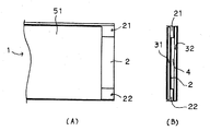
そして、その特徴的構造は、図1に示すように、その遮音板2には、一端から他端にわたり上方に開口した断面略コ字状の排水溝21、22を設け、この防音構造体1の上面で受けた雨水を外部に排水可能とするとともに、遮音板2と下吸音層32との間にその排水溝21、22と並列して吸音空気層4を設けたことを特徴とする。排水溝21,22は断面略コ字状に限定されず、吸音空気層4を構成する一定の深さがあれば、断面略U字状等の形状が採用できる。
(First Embodiment)
As shown in FIG. 1, the characteristic structure is that the sound
図1、図2、図3(A)に図示の構造は、金属製の遮音板2、例えば、厚さ1.6mm亜鉛めっき鋼板からなる遮音板2の長手方向側縁部の一方において、下方に屈曲加工し、内側壁板21a、底板21b、外側壁板21cからなる上方に開口した断面略コ字状の排水溝21を設け、同様に他方の長手方向側縁部にも同様にして、排水溝22(内側壁板22a、底板22b、外側壁板22c)を設ける。
The structure shown in FIG. 1, FIG. 2 and FIG. 3 (A) has a metal sound
かくして、この排水溝21、22で挟まれる遮音板の平板部分23は、排水溝21、22より高く位置するので、防音構造体1の上面で受けた雨水は、この排水溝21、22に誘導、集水され、外部に排水可能となる。同時に、浸水に基づく上吸音層31を構成の吸音材の劣化、その他の金属部材の発錆などが防止でき、吸音材の重量増加の影響も回避できることになる。
Thus, since the flat plate portion 23 of the sound insulating plate sandwiched between the
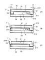
さらに、この排水溝21、22で挟まれる遮音板の平板部分23は、上吸音層31と密接して積層されるが、両端を底板21b、22bに裏面に接して配置した下吸音層32との間には、排水溝21、22の深さに相当する間隔を持った空間4が配置されることになり、この空間が下吸音層32の存在とあいまって、特に、低い周波数に対する吸音性能を向上させる作用がある。
なお、下方からの騒音の周波数に対して当該吸音空間が有効では無い場合には、当該吸音空間に吸音材を充填し、吸音層とすることもできる。
Further, the flat plate portion 23 of the sound insulating plate sandwiched between the
When the sound absorbing space is not effective for the frequency of noise from below, the sound absorbing space can be filled with a sound absorbing material to form a sound absorbing layer.
この図3(Aの)実施形態では、上吸音板31の端面と排水溝21、22の外側壁板21c、22cとの間に隙間t1、t2が設けられているが、この隙間は、雨水の集水にはある程度空けるのがよいが、過大に空けると防音性能が低下する恐れもあるので、雨水の流入に差支えない程度とすればよいものである。
In the embodiment of FIG. 3 (A), gaps t1 and t2 are provided between the end surface of the upper
さらに、この第1実施形態では、一方の排水溝21の外側壁板21cの上端部に外側横方向に折り曲げた屈曲部21dを設けて、これら防音構造体1を複数、列設配置し鋼製桁橋防音構造を構成した場合、隣り合って配置される他の防音構造体に設けられた他方の排水溝22の外側壁板22cの上端部をその屈曲部21dにより被覆できるようにするのが適当である。このとき、上吸音板31の上面が外側壁板22cの上端よりも低い位置であり、上吸音板と屈曲部21dの間に隙間を設けるようにすれば、雨水が排水溝21、22へ集水されやすく、好ましい。
Furthermore, in this first embodiment, a
かくして、複数の防音構造体1、1を列設配置したとき、防音構造体1の上面で受けた雨水が、両防音構造体の隙間から漏れることなく、排水溝21、22に集水できる利点が得られる。この目的には、前記屈曲部21dを折り返した略逆U字状に形成して、他方の排水溝22の外側壁板22cの上端部を挟み込むようにするのも好ましい。
Thus, when a plurality of
(第2実施形態)
図3(B)に例示する第2実施形態では、排水溝21を平面外形が矩形からなる遮音板2の長手方向に沿った一方の側縁部に設けるとともに、その排水溝21の外側壁板21c上端部分に、外側横方向に折り曲げた屈曲部21dを設けている。この構造は、先の図3(A)と同様である。
そして、これら防音構造体を複数、列設配置したとき、隣り合う防音構造体の遮音板2の他方の側縁部(先の図3(A)とは異なり排水溝は設けられていない)の上方に屈曲させた屈曲壁板24の先端部分を、その屈曲部21dが被覆できるように形成されている。
(Second Embodiment)
In the second embodiment illustrated in FIG. 3B, the
When a plurality of these soundproof structures are arranged in a row, the other side edge of the
この場合、かくして、この実施形態では、排水溝21が遮音板2の片側にだけ設けられているのであるが、防音構造体1、1の上面で受けた雨水が、両防音構造体1、1の隙間から漏れることなく、最終的には排水溝21に集水できるのである。
なお、この場合でも、排水溝が設けられていない遮音板2の他方の側縁部にはスペーサ25が遮音板2と下吸音層32との間に装着され、吸音空間4が第1実施形態と同様な間隔をもって形成されている。
また、平板23に排水溝21に向けて傾斜を設けると、集水しやすくなり好ましい。
In this case, thus, in this embodiment, the
Even in this case, the
Further, it is preferable to provide the flat plate 23 with an inclination toward the
(第3実施形態)
図3(C)に例示する第3実施形態では、排水溝21を平面外形が矩形からなる遮音板2の長手方向に沿った一方の側縁部に設けるとともに、他方の側縁部(先の図3(A)とは異なり排水溝は設けられていない)の上方に屈曲させた屈曲壁板24の先端部分に横方向の屈曲部24dを設けて、それら防音構造体1、1を複数、列設配置したとき、隣り合う防音構造体における排水溝21の外側壁板21cの上端部を、その屈曲部24dにより被覆できるよう構成されている。
すなわち、第2実施形態とは、図3(B)の屈曲部21dが省略された代わりに、図3(C)ように反対側に屈曲部24dが設けられ、実質的に同様な作用効果が得られるよう配置されているのである。したがって、その他の構造は、第2実施形態の場合と同様であるので説明を省く。
(Third embodiment)
In 3rd Embodiment illustrated in FIG.3 (C), while providing the
That is, in the second embodiment, instead of omitting the
以上説明した各実施形態において、前記吸音層31としては、撥水性フッ素樹脂フィルムで被覆したポリエステル繊維からなる吸音材によって厚さ25mm程度に構成すると、好ましい吸音性能、耐水性能が得られるので好適である。前記下吸音層32としても同様の構成を採用できるが、厚さ25mm程度のポリエステル繊維からなる吸音材のみで構成してもよい。なお、これらの撥水性フィルム、吸音材としては、この他公知のものが使用できる。
また、前記上吸音層31の上面、および下吸音層32の下面には孔明き板51、52を添着して、吸音層31、32の保護に役立たせるとともに、この吸音層31、32、遮音板2、排水溝21(22)、空気層4、孔明き板51、52を一体化して防音板ユニットを形成するのが、吸音構造体のハンドリング上より好ましいものとなる。この場合、穴明き板51、52は、適宜厚さのステンレス製金網、同エキスパンドメタル、パンチングメタル、グレーティングなどのように上下に多数の通気孔が設けられている板材が利用可能である。
In each of the embodiments described above, the
In addition,
(鋼製桁橋防音構造)
本発明の鋼製桁橋防音構造を図4、5を参照して説明する。
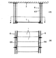
枕木7を支承して鉄道橋を構成している一組の鋼製桁6、6の間に、先に述べた本発明の防音構造体1、1を架け渡して配置したもので、そのI形鋼製桁6、6に断面L形の支承材66を桁行き方向に固定し、その支承材間66に前記防音構造体1、1を架け渡したことを特徴とするものである。
(Steel girder bridge soundproof structure)
The steel girder bridge soundproof structure of the present invention will be described with reference to FIGS.
The above-described
鋼製桁6がI形鋼製桁であり、鋼製桁の剛性を補強するために一定間隔で垂直補剛材63が設置されている場合は、先ず、対象となるI形鋼製桁(6、6)の対向面において、I形鋼製桁のフランジ62およびウエブ61に設置されているライナー状の垂直補剛材63に、横断面T字状の取付け金具65を配置し、この取付け金具65に縦断面L形の支承材66を桁方向(横方向)に取付け固定する。
When the
かくして、対向、固定された1組の支承材66は、水平支承部66aを内側に突出し向き合わせて配置されるので、必要枚数の防音構造体1を並列させ、その両端部分をこの支承材66の水平支承部66aに架け渡し、固定ボルト17で固定することによって、本発明の鋼製桁橋防音構造が得られる。
Thus, the pair of
また、前記支承材は縦断面L形に限らず、H形、T形等の水平支承部66aを有する形状であればよい。また、対向した1組の支承材に代えて、1体の支承材を鋼製桁間に掛け渡してもよい。また、防音構造体1は、支承材66の水平支承部66aの下面に取り付け、固定ボルトで固定するようにしてもよい。
The bearing material is not limited to the L-shaped longitudinal section, and may be any shape having a
さらに、垂直補剛材63を備えていないI形鋼製桁の場合は、支承材66をI形鋼製桁のウエブ61に直接取り付け固定してもよい。また、鋼製桁がI形鋼ではない場合であっても、対向する側面に直接縦断面L形の支承材66を直接的、または側面に一定間隔で取り付けられた垂直部材などを介して間接的に取付けることにより、防音構造体1を固定することができ、本発明の鋼製桁橋防音構造が得られる。
Further, in the case of an I-shaped steel girder that does not include the
本発明の鋼製桁橋防音構造によれば、如上の本発明の防音構造体の利点を鋼製桁橋として発揮できる。すなわち、鋼製桁橋を通行する車両などの騒音を吸音できるうえ、上面に受けた雨水を排水できる排水溝をその内部に備えているから、降雨時に排水可能となるとともに、浸水による吸音材の材質劣化、金属部材の発錆や、吸音材の重量増加も回避できる。さらに、内部に吸音空間を持つので幅広い周波数の騒音に対応できるうえ、鋼製桁橋の下方の道路の走行騒音など防音にも有効な利点が得られるのである。 According to the steel girder bridge soundproof structure of the present invention, the advantages of the above soundproof structure of the present invention can be exhibited as a steel girder bridge. In other words, it can absorb the noise of vehicles passing through steel girder bridges and has a drainage groove inside it that can drain the rainwater received on the top surface. Material deterioration, rusting of metal members, and increase in weight of sound absorbing material can also be avoided. In addition, since it has a sound absorbing space inside, it can handle a wide range of noises, and it also provides an effective advantage for soundproofing such as running noise on the road below the steel girder bridge.
1:防音構造体
2:遮音板、21、22:排水溝、21a、22a:内側壁板、21b、22b:底板、21c、22c:外側壁板、21d:屈曲部、23:平板部分
31:上吸音層、32:下吸音層
4:吸音空気層
1: soundproof structure 2: sound insulation plate, 21, 22: drainage groove, 21a, 22a: inner wall plate, 21b, 22b: bottom plate, 21c, 22c: outer wall plate, 21d: bent portion, 23: flat plate portion 31: Upper sound absorbing layer, 32: Lower sound absorbing layer 4: Sound absorbing air layer
Claims (8)
The steel girder is an I-shaped steel girder, a support member having an L-shaped cross section is fixed to the I-shaped steel girder in the direction of the girder, and the soundproof structure is bridged between the support members. The steel girder bridge soundproof structure according to claim 7.
Priority Applications (1)
| Application Number | Priority Date | Filing Date | Title |
|---|---|---|---|
| JP2008172103A JP4619425B2 (en) | 2008-07-01 | 2008-07-01 | Soundproof structure and steel girder bridge soundproof structure |
Applications Claiming Priority (1)
| Application Number | Priority Date | Filing Date | Title |
|---|---|---|---|
| JP2008172103A JP4619425B2 (en) | 2008-07-01 | 2008-07-01 | Soundproof structure and steel girder bridge soundproof structure |
Publications (2)
| Publication Number | Publication Date |
|---|---|
| JP2010013802A true JP2010013802A (en) | 2010-01-21 |
| JP4619425B2 JP4619425B2 (en) | 2011-01-26 |
Family
ID=41700149
Family Applications (1)
| Application Number | Title | Priority Date | Filing Date |
|---|---|---|---|
| JP2008172103A Active JP4619425B2 (en) | 2008-07-01 | 2008-07-01 | Soundproof structure and steel girder bridge soundproof structure |
Country Status (1)
| Country | Link |
|---|---|
| JP (1) | JP4619425B2 (en) |
Cited By (2)
| Publication number | Priority date | Publication date | Assignee | Title |
|---|---|---|---|---|
| JP2016118064A (en) * | 2014-12-22 | 2016-06-30 | 新中央工業株式会社 | Sound insulating board immobilization structure such as road sound insulation wall, sound insulating board fastener and sound insulating board |
| JP2022096676A (en) * | 2020-12-18 | 2022-06-30 | Jfeスチール株式会社 | Steel bridge inter-girder cover structure and steel bridge provided with the same |
Citations (7)
| Publication number | Priority date | Publication date | Assignee | Title |
|---|---|---|---|---|
| JPS4993617U (en) * | 1972-11-30 | 1974-08-13 | ||
| JPS4993616U (en) * | 1972-11-30 | 1974-08-13 | ||
| JPS5630212U (en) * | 1979-08-14 | 1981-03-24 | ||
| JPS5663712U (en) * | 1979-10-24 | 1981-05-28 | ||
| JPH08120624A (en) * | 1994-10-24 | 1996-05-14 | Daido Concrete Kogyo Kk | Shielding device of clearance between bridge body in parallel |
| JP2000144968A (en) * | 1998-11-04 | 2000-05-26 | Kawasaki Steel Corp | Sound absorption material and sound absorption panel |
| JP2003342912A (en) * | 2002-05-24 | 2003-12-03 | East Japan Railway Co | Sound isolation method of steel girder bridge |
-
2008
- 2008-07-01 JP JP2008172103A patent/JP4619425B2/en active Active
Patent Citations (7)
| Publication number | Priority date | Publication date | Assignee | Title |
|---|---|---|---|---|
| JPS4993617U (en) * | 1972-11-30 | 1974-08-13 | ||
| JPS4993616U (en) * | 1972-11-30 | 1974-08-13 | ||
| JPS5630212U (en) * | 1979-08-14 | 1981-03-24 | ||
| JPS5663712U (en) * | 1979-10-24 | 1981-05-28 | ||
| JPH08120624A (en) * | 1994-10-24 | 1996-05-14 | Daido Concrete Kogyo Kk | Shielding device of clearance between bridge body in parallel |
| JP2000144968A (en) * | 1998-11-04 | 2000-05-26 | Kawasaki Steel Corp | Sound absorption material and sound absorption panel |
| JP2003342912A (en) * | 2002-05-24 | 2003-12-03 | East Japan Railway Co | Sound isolation method of steel girder bridge |
Cited By (2)
| Publication number | Priority date | Publication date | Assignee | Title |
|---|---|---|---|---|
| JP2016118064A (en) * | 2014-12-22 | 2016-06-30 | 新中央工業株式会社 | Sound insulating board immobilization structure such as road sound insulation wall, sound insulating board fastener and sound insulating board |
| JP2022096676A (en) * | 2020-12-18 | 2022-06-30 | Jfeスチール株式会社 | Steel bridge inter-girder cover structure and steel bridge provided with the same |
Also Published As
| Publication number | Publication date |
|---|---|
| JP4619425B2 (en) | 2011-01-26 |
Similar Documents
| Publication | Publication Date | Title |
|---|---|---|
| JP6271213B2 (en) | Sound absorbing panel and sound barrier | |
| JP5308006B2 (en) | Sound absorbing structure | |
| RU2324795C2 (en) | Kochetov acoustical barrier | |
| US8371084B2 (en) | Suspended ceiling structure and layer-core-layer acoustic ceiling panel therefor | |
| JP5308245B2 (en) | Wall structure | |
| JP4619425B2 (en) | Soundproof structure and steel girder bridge soundproof structure | |
| KR200252277Y1 (en) | Soundproofing Panel | |
| JP2009215725A (en) | Sound insulation board for steel girder, and sound insulation structure using the same | |
| JP2007255052A (en) | Translucent soundproof plate and sound insulating wall | |
| JP7175734B2 (en) | sound absorbing panel | |
| JP2020133281A (en) | Sound absorbing panel | |
| JP6236777B2 (en) | Sound insulation for road bridges | |
| JP4650889B2 (en) | Sound barrier | |
| JP4437278B2 (en) | Soundproof plate and soundproof structure using the same | |
| JP3658644B2 (en) | Reduction structure of traffic noise radiated upward | |
| JP2005030116A (en) | Visible soundproof wall for moving sound source and soundproof unit | |
| JP4871709B2 (en) | Soundproof unit mounting structure | |
| JP4251969B2 (en) | Soundproofing device and soundproofing wall | |
| JP7481931B2 (en) | Sound insulation wall and sound insulation panel used therein | |
| KR102088795B1 (en) | Expansion joint structure of a bridge having function of draining and method for making that structure | |
| US20170275834A1 (en) | Anti-noise facility for tracked transport road and tracked transport road provided with such a facility | |
| JP4091836B2 (en) | Noise barrier for railway | |
| JP2831562B2 (en) | Noise barrier | |
| JP6065566B2 (en) | Sound insulation for road bridges | |
| JP7401194B2 (en) | sound absorbing panel |
Legal Events
| Date | Code | Title | Description |
|---|---|---|---|
| A711 | Notification of change in applicant |
Free format text: JAPANESE INTERMEDIATE CODE: A711 Effective date: 20100303 |
|
| A977 | Report on retrieval |
Free format text: JAPANESE INTERMEDIATE CODE: A971007 Effective date: 20100428 |
|
| A131 | Notification of reasons for refusal |
Free format text: JAPANESE INTERMEDIATE CODE: A131 Effective date: 20100514 |
|
| A521 | Request for written amendment filed |
Free format text: JAPANESE INTERMEDIATE CODE: A523 Effective date: 20100712 |
|
| A131 | Notification of reasons for refusal |
Free format text: JAPANESE INTERMEDIATE CODE: A131 Effective date: 20100730 |
|
| A521 | Request for written amendment filed |
Free format text: JAPANESE INTERMEDIATE CODE: A523 Effective date: 20100928 |
|
| TRDD | Decision of grant or rejection written | ||
| A01 | Written decision to grant a patent or to grant a registration (utility model) |
Free format text: JAPANESE INTERMEDIATE CODE: A01 Effective date: 20101026 |
|
| A01 | Written decision to grant a patent or to grant a registration (utility model) |
Free format text: JAPANESE INTERMEDIATE CODE: A01 |
|
| A61 | First payment of annual fees (during grant procedure) |
Free format text: JAPANESE INTERMEDIATE CODE: A61 Effective date: 20101026 |
|
| FPAY | Renewal fee payment (event date is renewal date of database) |
Free format text: PAYMENT UNTIL: 20131105 Year of fee payment: 3 |
|
| R150 | Certificate of patent or registration of utility model |
Ref document number: 4619425 Country of ref document: JP Free format text: JAPANESE INTERMEDIATE CODE: R150 Free format text: JAPANESE INTERMEDIATE CODE: R150 |
|
| R250 | Receipt of annual fees |
Free format text: JAPANESE INTERMEDIATE CODE: R250 |
|
| R250 | Receipt of annual fees |
Free format text: JAPANESE INTERMEDIATE CODE: R250 |
|
| R250 | Receipt of annual fees |
Free format text: JAPANESE INTERMEDIATE CODE: R250 |
|
| R250 | Receipt of annual fees |
Free format text: JAPANESE INTERMEDIATE CODE: R250 |
|
| R250 | Receipt of annual fees |
Free format text: JAPANESE INTERMEDIATE CODE: R250 |
|
| R250 | Receipt of annual fees |
Free format text: JAPANESE INTERMEDIATE CODE: R250 |
|
| R250 | Receipt of annual fees |
Free format text: JAPANESE INTERMEDIATE CODE: R250 |
|
| R250 | Receipt of annual fees |
Free format text: JAPANESE INTERMEDIATE CODE: R250 |