JP3658644B2 - Reduction structure of traffic noise radiated upward - Google Patents
Reduction structure of traffic noise radiated upward Download PDFInfo
- Publication number
- JP3658644B2 JP3658644B2 JP11708399A JP11708399A JP3658644B2 JP 3658644 B2 JP3658644 B2 JP 3658644B2 JP 11708399 A JP11708399 A JP 11708399A JP 11708399 A JP11708399 A JP 11708399A JP 3658644 B2 JP3658644 B2 JP 3658644B2
- Authority
- JP
- Japan
- Prior art keywords
- sound absorbing
- sound
- plate
- traffic noise
- road
- Prior art date
- Legal status (The legal status is an assumption and is not a legal conclusion. Google has not performed a legal analysis and makes no representation as to the accuracy of the status listed.)
- Expired - Lifetime
Links
Images


Description
【0001】
【発明の属する技術分野】
本発明は、両側が壁で上部に開口を有する道路又は鉄道における交通騒音の低減構造に関する。
【0002】
【従来の技術】
高速道路や鉄道の騒音防止のために、道路あるいは線路の両側に直形の防音壁又は上端がしのび返し形構造である防音壁を設置する方法、さらには半地下式の堀割構造として堀割内面に吸音板を設置する方法、あるいは両側の壁と天井部とで覆い囲む方法などが採られてきている。
【0003】
上部に天井あるいは覆いを設けたトンネル型の道路は、防音性能は高いが、(1)排気ガスが充満するために排気設備を必要とする、(2)照明設備を必要とする、といった問題点があった。これらの問題点を解決する方法として、例えば特公昭54−18492号公報には、車道を取り囲むようにトンネル状の防音壁を設け、その防音壁に外部が見える程度の間隔の間隙構造(開口部)を設けることが記載されている。この方法によれば、排気及び照明の問題はほぼ解決できるが、防音壁に設けた開口部から音がそのまま抜け出て道路側方を含む周囲に放射されるので、防音効果という面からは不十分である。
【0004】
一方、特開昭49−17026号公報には、堀割構造の道路の上方開口部に1又は複数の帯状の吸音板を道路の延長方向に沿って鉛直に設置することが記載されている。同公報によれば、吸音板に衝突した音が消滅又は減衰するため、道路上で発生した音のうち水平方向成分が減少し、道路沿いの家屋等に伝わる騒音を軽減できる。
また、特開昭55−111705号公報には、両側に防音壁を設けるか又は堀割構造とした道路の上方開口部に、吸音材等からなる上下方向に開放した多数の筒型セルの集合体を設置することが記載されている。同公報によれば、垂直又はそれに近い角度の指向性を持つ音はそのまま筒型セルを抜け出るが、それ以外の音は筒型セルの内壁に衝突し、あるいは衝突を繰り返して減衰するため、上方開口部から放射される音は道路側方への指向性が小さくなり、道路側方での騒音を軽減できる。
【0005】
【発明が解決しようとする課題】
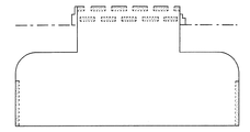
ところで、近年、堀割形道路の近傍に高層ビルディングが建設され、上部階で交通騒音が問題となる場合がある。この場合の交通騒音の堀割道路周辺の音圧分布状態を、公知の境界要素法を用い数値解析によりシミュレーションした(参考;日本機械学会論文集(C編)60巻453号(昭和59年5月)P.848-856)。図26(a)に示す堀割道路において、Sに音源を配置したときの堀割道路内及び地表の幅80m高さ40mの範囲内で観測される音場のシミュレーション結果を図26(b)に示す。なお、この解析対象の堀割道路は、全幅W1:20.5m、天井までの高さH1:7.0m、開口部の幅W2:9.5m、既設吸音板の高さh1:4m、天井から地表までの高さH2:2.5m、ブロック塀の高さH3:1.8mとし、音源の周波数は1000Hzとした。このシミュレーション結果をみると、上方ほど音波が道路側方へ放射されるという広範な広がり角度を有する音場であることが分かった。
【0006】
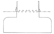
この音波の広がりを抑制する方法として、図27に示すように、堀割道路の開口部に両面を吸音表面とした複数列の吸音板(高さh2:2.7m、幅t2:0、2m、吸音表面全長:43.2m)を道路の延長方向に沿って鉛直に設置すると(a)、特開昭49−17026号公報又は特開昭55−111705号公報に記載されたと同様に、水平方向成分を持つ音が吸音板に衝突し、あるいは衝突を繰り返して減衰するため、開口部から吸音板を通って放射される音の側方への指向性を弱め道路側方への広がりを抑えることが可能となる(b)。しかし、十分な減衰効果を実現するためには、前記のように相当な鉛直方向長さを持つ吸音板を多数列並べる必要があり、経済性に問題が生じる。
【0007】
本発明は、従来技術の上記問題点に鑑みてなされたもので、両側が壁で上部に開口を有する道路又は鉄道において、開口部から上方に放射される交通騒音を低減し、経済的であり、かつ自然の換気や採光を大きく阻害しない交通騒音の低減構造を得ることを目的とする。
【0008】
【課題を解決するための手段】
本発明では、両側が壁で上部に開口を有する道路又は鉄道において上方に放射される交通騒音を効率的に低減するため、吸音板の吸音表面が鉛直方向を向くように設置するのではなく、複数の吸音板の吸音表面が水平になるように設置するとともに、隣接する吸音板同士が互いに間隔をおくように設置する。
これにより、交通騒音源から上方へ放射される直接音が吸音面に衝突する面積、つまり有効吸音面積を広く取ることができ、効率よく吸音される。また、隣接する吸音板の間に隙間があることから、自然の換気及び採光が確保される。
【0009】
具体的には、本発明の低減構造は、(1)道路又は鉄道の延長方向に垂直な断面をみたとき、開口部に水平な下向きの吸音表面を有する複数の吸音板が互いに間隔をおいて設置され、前記吸音板の広面の1つが前記吸音表面となり、かつ両側面も吸音表面となっていて、前記吸音板が吸音材と該吸音材を取り囲む枠体からなり、前記枠体の孔のない裏面板 が前記吸音材の裏面側を遮蔽している、というものである。あるいは、(2)開口部に水平な下向きの吸音表面を有する複数の吸音板が互いに間隔をおき、かつ上下に複数段設置され、前記吸音板の鉛直方向の投影がほぼ接するか又は一部重なり合うようにされ、前記吸音板の広面の1つが前記吸音表面となり、前記吸音板が吸音材と該吸音材を取り囲む枠体からなり、前記枠体の孔のない裏面板が前記吸音材の裏面側を遮蔽している、というものである。
【0010】
この低減構造では、吸音板の広面が吸音表面とされ、該吸音表面が下向きに水平になるように設置されている。このため直接波に対する吸音面積が大きい。両側面を吸音表面としたときはさらに吸音面積が大きくなる。
この低減構造では、複数の吸音板は互いに間隔をおいて設置されている。このため自然換気と採光を確保できるが、反面、その隙間から直接音や反射音が上方に放射される。しかし、複数の吸音板を上下に複数段に設置し、その鉛直方向の投影がほぼ接するか又は一部重なり合うようにすることで、上段の吸音板がそれを吸収し効率的に音を減衰させることができる。
また、この低減構造では、吸音板を道路又は鉄道の延長方向に沿って設置することができる。この場合、側方への騒音低減効果が大きく、しかも延長方向に沿った全域で均等な騒音低減効果が得られる。
【0011】
前記低減構造では、開口部を覆う吸音板の水平方向の間隔を狭くしたり、吸音板を多段に設置した場合などは、その分、下方の路上空間への光が遮られる。この採光性の低下を補うため、必要に応じて、吸音板の裏面側の表面を太陽光を反射するような材質にする(例えば、吸音材の裏面を覆う裏面板をアルミ製とする)ことができる。吸音表面についても同様とし(例えば、吸音材の前面に配置した多孔板をアルミ製とする)、吸音板の両側面についても適宜太陽光を反射する材質とすることができる。水平な吸音表面を有する複数の吸音板が上下に複数段設置されている場合、下位の裏面側表面と上位の吸音表面との間で太陽光が散乱し、下方の路上空間へ光が導かれやすくなる。太陽光を反射、散乱させる裏面側表面の形状としては、例えば平面又は上に凸の形状が考えられる。
【0012】
【発明の実施の形態】
以下、図1〜図25を参照して、本発明に係る交通騒音の低減構造の具体例及び参考例をいくつか説明する。
図1に示す構造は、堀割道路の開口部に、傾斜した吸音表面を有する複数の吸音板を、道路の延長方向に沿って、かつ水平方向に互いに同じ間隔aをおいて設置したものであり、特に道路左側での騒音の低減を重視したもので、道路左側へ向かう音に対する吸音面積が広くなっている。この場合、少なくとも下向きの広面1が吸音表面となっていればよいが、より高い騒音低減性能を求めるのであれば、一部又は全部の吸音板の上向きの広面2及び下向きの狭面3も吸音表面とするとよい。
なお、この例では、各吸音板の鉛直方向の投影をみると間隔bが空いているが、騒音低減性能を重視するのであれば、より多数の吸音板を密に設置したり、各吸音板の広面の幅を大きくして間隔bを狭め、あるいは鉛直方向の投影がほぼ接するか(b=0)又は一部重なり合うようにしてもよい。その場合でも、各吸音板が水平方向に間隔をおいて設置されているので、自然換気及び採光が確保される。
【0013】
図2に示す構造は、図1の構造のように吸音板を同方向に傾斜させて配置するのではなく、左右対象に傾斜して配置したもので、道路の左右両側へ向かう騒音を同じように低減する効果がある。
図3に示す構造は、傾斜の向きが逆にされた吸音板が上下2段に設置され、各段の吸音板は水平方向に互いに間隔をおき、上下の段でみると吸音板は千鳥配置となり、鉛直方向の投影が一部重なり合うようにされている。この構造は、騒音源からの直接音が開口部を抜け出るのを遮っている。
図4に示す構造は、断面くの字形の複数の吸音板を水平方向に互いに間隔をおいて設置したもの、図5に示す構造は、同形状の吸音板を水平方向に互いに間隔をおき、かつ各吸音板の鉛直方向の投影がほぼ接するように設置されたもの、図6に示す構造は、くの字が上下に2つ連なった形状の吸音板を水平方向に互いに間隔をおいて設置したものである。いずれも吸音面積を広く取ることができ、外部への騒音を減衰させる効果が高い。
【0014】
図7に示す構造は、堀割道路の開口部に、道路の延長方向に沿って、水平な下向きの吸音表面4を有する複数の吸音板を水平方向に同じ間隔cをおき、かつ上下2段に設置したものである。上下の吸音板は千鳥配置となり、鉛直方向の投影がちょうど接するようにされている。吸音表面4が水平であるため、直接音に対する吸音面積が広い。この場合、上下の吸音板の少なくとも下向きの広面4が吸音表面となっていればよいが、より高い騒音低減性能を求めるのであれば、下段の吸音板はその一部又は全部で上向きの広面5及び左右の狭面6、7も吸音表面とし、上段の吸音板はその一部又は全部で左右の狭面6、7も吸音表面とするとよい。
図8に示す構造は、各段の吸音板の水平方向の間隔を狭めたもので、鉛直方向の投影が重なるようにされ、騒音源からの直接音が開口部を抜け出るのを遮っているため、騒音低減性能が高い。
【0015】
図9に示す構造は、傾斜した下向きの吸音表面を有する吸音板と水平な下向きの吸音表面を有する吸音板が2段に設置され、それぞれの段では各吸音板は水平方向に間隔をおいて設置されている。図3に示す構造とほぼ同等といえるが、それより設置面積がやや節約できる。
図10に示す構造は、両面が吸音表面とされそれが鉛直方向に向く吸音板と水平な下向きの吸音表面を有する吸音板が2段に設置されたものである。下段の吸音板により音の斜め方向成分を吸音し、残った鉛直方向への直進成分を上段の吸音板で効果的に吸収、遮弊する効果がある。
図11に示す構造は、内側が吸音表面とされた一般的な防音壁と傾斜した下向きの吸音表面を有する吸音板を組み合わせたものである。
図12に示す構造は、両面が吸音表面とされそれが鉛直方向に向く吸音板が上下2段に設置され、各段の吸音板は水平方向に互いに間隔をおき、上下の段でみると吸音板は千鳥配置となっている。この場合、同じ数の吸音板を1段に密に設置するより、自然換気及び採光の点で有利となり、上段の吸音板の下端と下段の吸音板の上端の間隔を空けるとさらにその傾向が強まる。
【0016】
図13に示す吸音板は上記の交通騒音の低減構造に使用される吸音板の一例であり、例えばアルミ押出形材からなる枠部材11、表面を保護フィルムに覆われた吸音材12、例えばアルミ製のパンチングメタル等からなり吸音材の前面及び両側面を覆う多孔板13、枠部材11の上側の面(裏面の板)の内側に貼り付けられた制振材14からなる。この吸音板では、上記枠部材11及び多孔板13が吸音材12を取り囲む中空の枠体を構成する。枠部材11の裏面の板には係止部11aが形成され、ここに例えばボルトのヘッド等を嵌入させ、堀割道路等の開口部に吊すことができるようにされている。また、図14に示す吸音板も似たような構造を持ち、上側の面(裏面の板)が上に凸の曲面(円弧形)となった枠部材21、吸音材22、多孔板23、制振材24からなる。この吸音板では、上記枠部材21及び多孔板23が吸音材22を取り囲む中空の枠体を構成する。いずれの吸音板も下面と両側面の一部が吸音表面であり、堀割道路等の開口部に水平又は傾斜して設置される。
【0017】
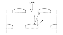
これらの吸音板は、枠部材の上側の面(裏面の板)が水平又は上に凸の曲面を有し、これがアルミのような金属であれば太陽光をよく反射し、多孔板もアルミのような金属であれば太陽光をよく反射する。従って、図15に示すように、例えば上下2段にこれらの吸音板を設置したような場合、下段の吸音板の上側の面で反射された太陽光が上段の吸音板の吸音表面(多孔板)に反射され、両者の間で太陽光が散乱して下方の路上空間へ光が導かれやすくなり、採光性の低下を補うことができる。あるいは、吸音板を多段に設置しない場合でも、傾斜した(例えば図1参照)又は湾曲した上側の面に太陽光が反射し、下方の路上空間へ光が導かれる。なお、塗装などで背面の板の色を太陽光をよく反射する色にしてもよい。
また、枠部材の上側の面(裏面の板)が水平面に対し傾斜又は上に湾曲していると、その面上を水が流れやすいことから降雨時の排水に有利であり、付着した汚れが雨水で除去されやすいという効果もある。この場合、裏面の板(又は枠部材全体)の表面をフッ素系樹脂等の親水性塗膜で被覆しておけば、さらに効果的である。なお、上側の面が凸形状をもつものであれば、例えば図16(a)〜(c)のように3角形状、台形状等、平面的な凸形状をもつものでも、採光、排水等の面で図14の湾曲形状のものと同様の作用効果を有する。
さらに、図13及び図14に例示した吸音板のように、裏面の板の内側に制振材を貼り付けた場合、その板の振動が抑制され、例えば雨落下により発生する雨音の減音作用が得られる。この作用は、裏面の板(又は枠部材全体)として、それ自体で制振性を有する板材、例えば粘弾性を示す制振樹脂を弾性板の間に挟んだサンドイッチ制振板(例;鋼板やアルミ板でシート状の制振樹脂を挟んだ制振鋼板や制振アルミ板)等を使用しても同様に得ることができる。
【0021】
図17に、吸音材を取り囲む中空の枠体の一方の広面と他の面を吸音表面とした吸音板の他の例として、下向きの広面と両側の狭面(側面)を吸音表面とした吸音板を示す。図17(a)はその基本構造の一例を示すもので、吸音材32とそれを取り囲む中空矩形の枠体からなり、この枠体は、吸音材32の裏面側に配置された板部材31と、吸音材32の前面側及び両側に配置され板部材31に固定された多孔板33で構成される。
なお、図17(a)の吸音板では両側の狭面を吸音表面としたが、図17(b)のように複数の吸音板を横に接続して使用する場合には、狭面の吸音表面は両端の吸音板にのみ要求されるから、このような場合、両端の吸音板は広面と使用時に外側になる片面だけを吸音表面とし、内側の吸音板は広面だけを吸音表面とすればよい。
【0018】
先に図13〜14に示した吸音板と同じであるが、多孔板33はパンチングメタルやエキスパンドメタルなどからなり、アルミのほか、鋼板、ステンレス鋼板などで形成すればよい。板部材31も多孔板33と同様の素材で形成でき、例えば板材、アルミ押出材などが利用できる。吸音材32はグラスウール、ロックウール、不織布等の繊維質吸音材が利用でき、雨水などからの防水のためポリフッ化ビニルなどのフィルムで被覆してもよい。なお、繊維質以外の吸音材も利用できる。グラスウールなどの繊維質吸音材を用いる場合、音源側にかさ密度の小さい吸音材を配し、背後側にかさ密度の大きい吸音材を配して密度勾配型の積層構造とすることで騒音低減性能を向上させることができ、かさ密度32kg/m3〜48kg/m3の吸音材を用いるのが望ましい。また、吸音材32の前面及び背面に空気層34を設けることでも騒音低減性能を向上せしめることができ、その層厚は10〜30mmとするのが望ましい。
【0019】
上記吸音板は、のちほど図18〜図19を参照して具体的に説明するように、少なくとも吸音材と該吸音材を取り囲む枠体からなり、前記枠体の一方の広面と2つの狭面のうち少なくとも1面が吸音表面とされた吸音板において、(1)吸音材が互いに別体の広面吸音材(広面にのみ面する吸音材)と狭面吸音材(主として狭面に面し、広面にも面する吸音材)からなり、それぞれ枠体の内側に保持され、各吸音材の吸音表面側(吸音表面を構成する多孔板に向く側)及び背面側に必要に応じて空気層が設けられている、あるいは(2)吸音材が一体の吸音材からなり、枠体の内側に保持され、同じく該吸音材の吸音表面側(吸音表面を構成する多孔板に向く側)及び背面側に必要に応じて空気層が設けられている、ということもできる。
なお、上記吸音板において、どの吸音表面についても吸音材厚さが十分である、密度勾配型の積層構造である、空気層と有効に組み合わされるなどの手段により、どの吸音表面においてもほぼ同等の騒音低減性能を実現することが望ましい。また、騒音低減性能を損なわないために、吸音材の取付部材や保持部などによって吸音材表面を塞ぐ面積はできるだけ小さくする、吸音材がフィルムで被覆されている場合は、フィルムの振動を拘束しないため、吸音材の取付部材や保持部と吸音材との接触面積をなるべく小さくする、等の工夫が望まれる。以下説明する図18、19の各例はこの要求を満たすために工夫されたものである。
【0020】
図18(a)に示す吸音板は、板部材41と多孔板43からなる枠体と、その枠体に囲まれた吸音材42a、42bからなり、板部材41には、吸音板の断面剛性を確保し、吸音材42aを保持するための保持部41aが一体的に設けられている。この保持部41a(及び連結部41b)は例えばアルミ押出形材などで板部材41と一体成形してもよく、別体で成形したものを一体に組み付けてもよい。広面を吸音するための吸音材42aは板部材41及び多孔板43と空気層44aを隔てて配置され、狭面を吸音するための吸音材42bも板部材41及び多孔板43と空気層44bを隔てて配置される。このとき吸音材42bは、騒音低減性能を損なわないように、帯状又はワイヤ状の複数の取付部材45で間隔を置いて所々保持し、保持部41aにリベットやタッピングネジで固定される。
【0021】
図18(b)に示す吸音板は、板部材51と多孔板53からなる枠体と、その枠体に囲まれた吸音材52a、52bからなり、板部材51には、吸音板の断面剛性を確保し、かつ吸音材52aを保持する保持部51aと吸音材52bを保持する保持部51cが一体的に設けられている。この板部材51でも、保持部51a(及び連結部51b)及び保持部51cをアルミ押出形材などで一体成形することができる。吸音材52aは板部材51及び多孔板53と空気層54aを隔てて配置され、吸音材52bは多孔板53との間に空気層54bを隔てて配置され、かつその背面(保持部51aの側)にも空気層54bが設けられる。
【0022】
図19(a)に示す吸音板は、板部材61と多孔板63からなる枠体と、その枠体に囲まれた吸音材62a、62bからなり、板部材61は図18(a)と基本的に同一で保持部61aが一体的に設けられている。吸音材62bは断面半円筒形をなし、円弧部が狭面を向いて多孔板63に支持され、平面部が保持部61a(及び連結部61b)に支持されるので、別途取付部材や保持部を必要とすることなく、空気層64bを確保し枠体内に保持することができる。
図19(b)に示す吸音板は、狭面吸音のための新たな吸音材を配することなく、一体の吸音材72のみとしたものである。板部材71と多孔板73が枠体を構成し、板部材71には保持部71aが一体的に設けられ、一方、保持部71bは別体であり、例えばこの吸音板の両端(紙面に垂直方向)で支持され、吸音材72はこの保持部71a、71bにより空気層74aを隔てて枠体内に配置される。なお、保持部71a、71bは吸音材72の端部(図でいえば吸音材の左端)に設置されてもよい。
【0023】
続いて、図20〜図22に、吸音板の吸音表面が鉛直方向を向くように設置した場合と、水平方向に向くように設置した場合の騒音の減衰効果の比較を、数値シミュレーションで行った結果を示す。ここで、図20では高さh3:0.3m、幅t3:0.2m、両側面及び下面を吸音表面とした吸音板を等間隔で設置したものとし、図21では高さh4:0.9m、幅t4:0.2m、両側面を吸音表面としたものとし、図22では幅h5:1.5m、厚みt5:0.1m、下面のみ吸音表面とした吸音板を水平方向に1mの間隔をおき、上下2段に千鳥配置したものとし、その他の条件は図26及び図27と同じとした。
【0024】
図20〜図22の例では、断面における吸音表面の長さはそれぞれ12.8m、14.4m、14.5mと、ほぼ同じくらいであったが、開口部から放射される音波の広がり(音圧分布状態)をみると、本発明に係る図22の例が圧倒的に優れている。また、シミュレーション結果による道路両側25m地点における平均減音量(高さ0.2m〜40.2m間の41点での平均減音量)は、左25m地点ではそれぞれ9.0dB、8.4dB、14.7dB、右25m地点ではそれぞれ8.4dB、6.5dB、14.8dBであり、本発明に係る図22の効果量が他を上回っている。
このシミュレーション結果によれば、同じ吸音表面積あるいは同じ体積をもつ吸音板であっても、本発明の構造の方が優れた効果を奏することが分かる。
【0025】
次に、吸音板を水平方向に互いに間隔を置いて設置した場合について、吸音板の下向きに水平に向いた広面のみを吸音表面としたときと、さらに他の面を吸音表面としたときの騒音の低減効果を、これまでと同じく公知の境界要素法による数値シミュレーションによって調べた。
解析対称の掘割道路の構造は、図23(a)に示すように図26の構造と同じとした(ただし、H3:1m)。また、開口部に配置する吸音板の断面サイズは図22と同じとし、それぞれの水平方向の間隔dは0.5mとし、吸音表面の吸音性能としては、建設省で規定された斜入射吸音率で0.88の性能を有する1面吸音(水平下向きの広面のみが吸音表面)又は3面吸音(水平下向きの広面と鉛直の両狭面が吸音表面)とし、これを図23(b)に示すように上下2段に配置するものとした。そして、上下2段に配置した吸音板の吸音板上端同士の距離(上下段間隔)cが0.3mの場合と1.0mの場合に関して、1面吸音の吸音板を配置した場合と3面吸音の吸音板を配置した場合の2種類の場合の騒音低減効果の差異について検討した。
【0026】
図23(a)、(b)に示すように、掘割道路内のS1、S2を音源としたときの周囲における音の大きさを求め、掘割道路断面形状がほぼ左右対称であることを利用して、掘割内部の4車線を自動車が走行した場合に掘割内部の道路中心から25m地点における地上高さ0.2m〜40.2mの範囲の騒音レベルを各場合について算出し、開口部の対策がない場合と比較したときの騒音低減効果を求めた。その結果を図23(c)に示す。
図23(c)には、上下段間隔cが1.0mの場合においても、0.3mの場合においても、3面吸音板を使用した場合には、1面吸音板の場合に比べて3dB程度、騒音低減効果が増大することが示されている。なお、3面吸音の場合は1面吸音の場合に比べて吸音表面積は1.13倍{(1.5×10+0.1×20)/(1.5×10)}となり、単純に計算すれば吸音力の増加分としては+0.5dB(10log101.13)しか見込めないはずであるが、実際には+3dB程度の大きな騒音低減効果のアップが実現されることが示されている。このように吸音表面積増加分以上の効果が得られるのは、この吸音板配置では複数の吸音板が間隔を開けて配置され、その隙間を通過する音波が、面積は小さくても隙間に面する部分を吸音表面とすることにより効率よく吸音されるためである。
【0027】
上記のように、この吸音板配置において、3面吸音の場合は1面吸音と比較して騒音低減効果は3dB程度増大することが明らかになった。しかし、この騒音低減効果は吸音板の間隔dによって変化することが考えられる。そこで、次は間隔dを変えたときの騒音低減効果の差異を検討するため、堀割道路から外部に放射される騒音のエネルギーを評価することとし、道路進行方向に並行な断面について以下のような検討を行った。解析対称の掘割道路の構造は、図23(a)と同じとし、開口部に配置する吸音板の断面サイズは図23(b)と同じとし、この吸音板を道路進行方向に垂直に上下2段(上下段間隔:1m)に配置するものとし、また吸音表面の吸音性能としては、建設省で規定された斜入射吸音率で0.88の性能を有する1面吸音(水平下向きの広面のみが吸音表面)又は3面吸音(水平下向きの広面と鉛直の両狭面が吸音表面)とした。そして、吸音板同士の水平方向の間隔が0.5mの場合と1.0mの場合に関して、1面吸音の吸音板を配置した場合と3面吸音の吸音板を配置した場合の2種類の場合の騒音低減効果の差異について検討した。
【0028】
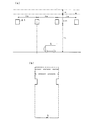
堀割道路の進行方向並行断面は図24(a)のようになっており、ほぼ一定間隔を置いて横梁81が設置されている。そこで一本の横梁から隣の横梁までの1ピッチ分を取り出した(b)に示すようなモデルを考えると、1ピッチ分から外部に放射される騒音全体のパワーはモデル上部の水平面を通過するパワーを積分することによって評価できる。この考え方に基づいてこれまでと同じく公知の境界要素法による数値シミュレーションを行い、各場合の騒音低減効果の差異について検討した。
シミュレーション結果から得た数値(水平方向の間隔が0.5mで、1面吸音の吸音板を配置した場合を基準=0dBとした、相対的な騒音低減効果)を表1に示す。
【0029】
【表1】
【0030】
表1から、3面吸音の場合の騒音低減効果は1面吸音の場合と比べて、吸音板の水平方向間隔が0.5mの場合は+3.1dB、1.0mの場合は+0.6dBであり、水平方向間隔によって大きく変化する。なお、この水平方向間隔が0.5mの場合の+3.1dBという数値は、図23(c)で見られた+3dB程度という数値とほぼ一致する。
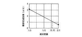
ここで得られたデータについて、縦軸を騒音低減効果、横軸を相対間隔(吸音板の水平方向間隔と吸音板の幅の比)としてグラフ化したものが図25であり、相対間隔が小さいほど騒音低減効果が大きく、3面吸音により少なくとも1dB以上の有意な騒音低減効果を得るためには相対間隔を0.6以下にすればよいことが分かる。少なくとも標準的と考えられる吸音板断面サイズ(厚さ:80〜200mm)、配置形態(上下段間隔:50〜200cm)であれば、相対間隔について同様の結果が得られる。
【0031】
【発明の効果】
本発明によれば、両側が壁で上部に開口を有する道路又は鉄道において、開口部から上方に放射される交通騒音を低減し、経済的であり、かつ自然の換気や採光を大きく阻害しない交通騒音の低減構造を得ることができる。
【図面の簡単な説明】
【図1】 交通騒音の低減構造の例を堀割道路の長手方向に垂直な断面で示すものである。
【図2】 交通騒音の低減構造の例である。
【図3】 交通騒音の低減構造の例である。
【図4】 交通騒音の低減構造の例である。
【図5】 交通騒音の低減構造の例である。
【図6】 交通騒音の低減構造の例である。
【図7】 交通騒音の低減構造の例である。
【図8】 交通騒音の低減構造の例である。
【図9】 交通騒音の低減構造の例である。
【図10】 交通騒音の低減構造の例である。
【図11】 交通騒音の低減構造の例である。
【図12】 交通騒音の低減構造の例である。
【図13】 本発明に係る吸音板の断面図である。
【図14】 本発明に係る吸音板の断面図である。
【図15】 吸音板による太陽光の反射を説明する図である。
【図16】 本発明に係る吸音板の断面を模式的に示す図である。
【図17】 本発明に係る吸音板の断面を模式的に示す図である。
【図18】 その具体的構造を示す図である。
【図19】 同じくその具体的構造を示す図である。
【図20】 比較例の構造における音圧分布状態のシミュレーション結果を示す図である。
【図21】 比較例の構造における音圧分布状態のシミュレーション結果を示す図である。
【図22】 本発明の構造における音圧分布状態のシミュレーション結果を示す図である。
【図23】 吸音板を水平2段に配置した場合について、3面吸音の場合と1面吸音の場合の騒音低減効果のシミュレーション結果を示す図である。
【図24】 吸音板を水平2段に配置した場合について、3面吸音の場合と1面吸音の場合の騒音低減効果を数値シミュレーションで評価する際の前提条件を説明する図である。
【図25】 その数値シミュレーション結果を示す図である。
【図26】 従来構造における音圧分布状態のシミュレーション結果を示す図である。
【図27】 比較例の構造における音圧分布状態のシミュレーション結果を示す図である。[0001]
BACKGROUND OF THE INVENTION
The present invention relates to a structure for reducing traffic noise on a road or railway having walls on both sides and an opening at the top.
[0002]
[Prior art]
In order to prevent noise on expressways and railways, either a straight type soundproof wall or a soundproof wall with a reversing structure at the top end is installed on both sides of the road or railroad. A method of installing a sound absorbing plate or a method of covering with a wall and a ceiling on both sides has been adopted.
[0003]
Tunnel-type roads with a ceiling or covering at the top are highly soundproof,(1)Exhaust equipment is required to fill the exhaust gas.(2)There was a problem of requiring lighting equipment. As a method for solving these problems, for example, in Japanese Patent Publication No. 54-18492, a tunnel-like soundproof wall is provided so as to surround the roadway, and a gap structure (opening portion) is formed so that the outside can be seen on the soundproof wall. ) Is described. According to this method, the problem of exhaust and lighting can be almost solved, but sound is emitted as it is from the opening provided in the soundproof wall and radiated to the surroundings including the side of the road. It is.
[0004]
On the other hand, Japanese Patent Application Laid-Open No. 49-17026 describes that one or a plurality of strip-shaped sound absorbing plates are vertically installed in an upper opening portion of a road having a moat split structure along the extending direction of the road. According to the publication, since the sound colliding with the sound absorbing plate disappears or attenuates, the horizontal component of the sound generated on the road is reduced, and noise transmitted to houses along the road can be reduced.
Japanese Patent Application Laid-Open No. 55-11705 discloses an assembly of a large number of cylindrical cells made of a sound absorbing material or the like that are opened in the vertical direction at the upper opening of a road having soundproof walls on either side or a moat structure. It is described to install. According to the publication, sound having a directivity at an angle close to or perpendicular to it exits the cylindrical cell as it is, but other sounds collide with the inner wall of the cylindrical cell, or repeatedly collide and attenuate. The sound radiated from the opening has less directivity to the side of the road, and the noise on the side of the road can be reduced.
[0005]
[Problems to be solved by the invention]
By the way, in recent years, a high-rise building has been constructed in the vicinity of the moat split road, and traffic noise may be a problem on the upper floor. In this case, the sound pressure distribution around the Horiwara road was simulated by numerical analysis using the well-known boundary element method (Reference: Proceedings of the Japan Society of Mechanical Engineers (C) Vol.60, No.453 (May 1984) ) P.848-856). FIG. 26 (b) shows the simulation result of the sound field observed on the Horiwara road shown in FIG. 26 (a), within the Horiwari road when the sound source is arranged in S, and in the range of 80m in width and 40m in the ground surface. . The analysis target moat split road has an overall width W1: 20.5 m, a height to the ceiling H1: 7.0 m, an opening width W2: 9.5 m, an existing sound absorbing plate height h1: 4 m, from the ceiling The height H2 to the ground surface was 2.5 m, the height of the block wall H3 was 1.8 m, and the frequency of the sound source was 1000 Hz. From this simulation result, it was found that the sound field has a wide spread angle such that the sound wave is emitted to the side of the road as it goes upward.
[0006]
As a method of suppressing the spread of this sound wave, as shown in FIG. 27, a plurality of rows of sound absorbing plates (height h2: 2.7 m, width t2: 0, 2 m, both sides at the opening of a moat split road) When the sound absorbing surface total length: 43.2 m) is installed vertically along the extending direction of the road (a), the horizontal direction is the same as described in JP-A-49-17026 or JP-A-55-11705. Since sound with components collides with the sound-absorbing plate or attenuates by repeated collisions, the directivity to the side of the sound radiated from the opening through the sound-absorbing plate is weakened, and the spread to the side of the road is suppressed. (B). However, in order to realize a sufficient damping effect, it is necessary to arrange a large number of sound absorbing plates having a considerable vertical length as described above, which causes a problem in economy.
[0007]
The present invention has been made in view of the above-described problems of the prior art, and is economical in reducing traffic noise radiated upward from an opening in a road or a railway having walls on both sides and having openings in the upper part. The object is to obtain a structure for reducing traffic noise that does not significantly impede natural ventilation and lighting.
[0008]
[Means for Solving the Problems]
In the present invention, in order to efficiently reduce traffic noise radiated upward in a road or railway having both sides walls and openings in the upper part, instead of installing the sound absorbing surface of the sound absorbing plate in the vertical direction, Multiple sound absorbersSound absorption surface is horizontalIt installs so that it may become, and it may install so that adjacent sound absorption boards may mutually space.
Thereby, the area where the direct sound radiated upward from the traffic noise source collides with the sound absorbing surface, that is, the effective sound absorbing area can be widened, and the sound is efficiently absorbed. Moreover, since there is a gap between adjacent sound absorbing plates, natural ventilation and lighting are ensured.
[0009]
Specifically, the reduction structure of the present invention is:(1)When the cross section perpendicular to the extension direction of the road or railway is viewed, a plurality of sound-absorbing plates having a downward sound-absorbing surface that is horizontal in the opening are installed at intervals.One of the wide surfaces of the sound absorbing plate is the sound absorbing surface, and both side surfaces are also sound absorbing surfaces. The sound absorbing plate is composed of a sound absorbing material and a frame surrounding the sound absorbing material, and the back of the frame without holes. Face plate Shields the back side of the sound absorbing materialThat's it. Or(2)A plurality of sound-absorbing plates having a downward sound-absorbing surface that is horizontal in the opening are spaced apart from each other and installed in multiple stages above and belowThe vertical projection of the sound absorbing plate is substantially in contact with or partially overlapping, and one of the wide surfaces of the sound absorbing plate is the sound absorbing surface, and the sound absorbing plate is composed of a sound absorbing material and a frame surrounding the sound absorbing material. The back plate having no holes in the frame shields the back side of the sound absorbing material.That's it.
[0010]
In this reduction structure, the wide surface of the sound absorbing plate is used as a sound absorbing surface, and the sound absorbing surface is disposed so as to be horizontal downward. For this reason, the sound absorption area with respect to a direct wave is large. When both side surfaces are sound absorbing surfaces, the sound absorbing area is further increased.
In this reduction structure, the plurality of sound absorbing plates are installed at intervals. For this reason, natural ventilation and lighting can be secured, but on the other hand, direct sound and reflected sound are radiated upward from the gap. However, by installing a plurality of sound absorbing plates in multiple stages above and below and making the vertical projections almost touch each other or partially overlap, the upper sound absorbing plate absorbs it and attenuates the sound efficiently. be able to.
Further, in this reduction structure, the sound absorbing plate can be installed along the extending direction of the road or railway. In this case, the noise reduction effect to the side is large, and a uniform noise reduction effect can be obtained over the entire area along the extending direction.
[0011]
In the reduction structure, when the horizontal interval of the sound absorbing plates covering the openings is reduced, or when the sound absorbing plates are installed in multiple stages, the light to the road space below is correspondingly blocked. To compensate for this decrease in daylighting, the back surface of the sound absorbing plate is made of a material that reflects sunlight as necessary (for example, the back plate covering the back surface of the sound absorbing material is made of aluminum). Can do. The same applies to the sound-absorbing surface (for example, a porous plate disposed on the front surface of the sound-absorbing material is made of aluminum), and both sides of the sound-absorbing plate can be appropriately made of a material that reflects sunlight.HorizontalA plurality of sound absorbing plates having sound absorbing surfacesMultiple steps up and downWhen installed, sunlight is scattered between the lower back surface and the upper sound absorbing surface, and the light is easily guided to the road space below. As the shape of the back side surface that reflects and scatters sunlight, for example, a flat surface or a convex shape can be considered.
[0012]
DETAILED DESCRIPTION OF THE INVENTION
Hereinafter, with reference to FIGS. 1-25, the specific example of the reduction structure of the traffic noise which concerns on this inventionAnd reference examplesSome are explained.
The structure shown in FIG. 1 is a structure in which a plurality of sound absorbing plates having inclined sound absorbing surfaces are installed at the opening of a moat split road along the road extension direction and at the same interval a in the horizontal direction. In particular, the reduction of noise on the left side of the road is emphasized, and the sound absorption area for the sound toward the left side of the road is widened. In this case, it is sufficient that at least the downward
In this example, when the vertical projection of each sound absorbing plate is viewed, the interval b is open, but if importance is placed on noise reduction performance, a larger number of sound absorbing plates may be installed densely, or each sound absorbing plate may be The width b may be increased to reduce the interval b, or the projections in the vertical direction may be substantially in contact (b = 0) or partially overlap. Even in that case, since the sound absorbing plates are installed at intervals in the horizontal direction, natural ventilation and lighting are ensured.
[0013]
The structure shown in FIG. 2 is not arranged with the sound absorbing plate inclined in the same direction as in the structure of FIG. 1, but is inclined with respect to the left and right objects. There is an effect of reducing.
In the structure shown in FIG. 3, the sound absorbing plates whose directions of inclination are reversed are installed in two upper and lower stages, and the sound absorbing plates in each stage are spaced apart from each other in the horizontal direction. Thus, the vertical projections are partially overlapped. This structure blocks direct sound from the noise source from exiting the opening.
The structure shown in FIG. 4 is a structure in which a plurality of sound absorbing plates having a cross-sectional shape are horizontally spaced from each other, and the structure shown in FIG. 5 is the same shape of sound absorbing plates spaced from each other in the horizontal direction. In addition, the structure shown in FIG. 6 is installed so that the projections in the vertical direction of the respective sound absorbing plates are almost in contact with each other, and the sound absorbing plates having a shape in which two “U” characters are connected in the vertical direction are spaced apart from each other in the horizontal direction. It is a thing. In any case, the sound absorption area can be widened, and the effect of attenuating external noise is high.
[0014]
In the structure shown in FIG. 7, a plurality of sound-absorbing plates having a horizontal sound-absorbing
The structure shown in FIG. 8 is such that the horizontal intervals of the sound absorbing plates at each stage are narrowed so that the projections in the vertical direction are overlapped to prevent direct sound from the noise source from exiting the opening. High noise reduction performance.
[0015]
In the structure shown in FIG. 9, a sound absorbing plate having an inclined downward sound absorbing surface and a sound absorbing plate having a horizontal downward sound absorbing surface are installed in two stages, and in each stage, the sound absorbing plates are spaced horizontally. is set up. Although it can be said that it is substantially equivalent to the structure shown in FIG. 3, the installation area can be saved somewhat.
The structure shown in FIG. 10 is a structure in which a sound absorbing plate having both surfaces as sound absorbing surfaces and a sound absorbing plate facing in the vertical direction and a sound absorbing plate having a horizontal downward sound absorbing surface are installed in two stages. The lower sound absorbing plate absorbs the oblique component of the sound, and the remaining vertical component is effectively absorbed and blocked by the upper sound absorbing plate.
The structure shown in FIG. 11 is a combination of a general soundproof wall having a sound absorbing surface on the inside and a sound absorbing plate having an inclined downward sound absorbing surface.
In the structure shown in FIG. 12, the sound absorbing surfaces on both sides are vertically arranged, and the sound absorbing plates are vertically arranged in two steps, and the sound absorbing plates in each step are spaced apart from each other in the horizontal direction. The board is staggered. In this case, it is more advantageous in terms of natural ventilation and lighting than if the same number of sound absorbing plates are densely arranged in one stage, and the tendency is further increased if the lower end of the upper sound absorbing plate is spaced from the upper end of the lower sound absorbing plate. Strengthen.
[0016]
The sound absorbing plate shown in FIG. 13 is an example of a sound absorbing plate used in the above-described traffic noise reduction structure. For example, the frame member 11 made of an extruded aluminum material, and the sound absorbing material 12 whose surface is covered with a protective film, for example, aluminum. It consists of a perforated plate 13 made of a perforated metal made of metal and covering the front surface and both side surfaces of the sound absorbing material, and a
[0017]
In these sound absorbing plates, the upper surface (back plate) of the frame member has a horizontal or convex curved surface, and if this is a metal such as aluminum, it reflects sunlight well, and the porous plate is also made of aluminum. Such a metal reflects sunlight well. Therefore, as shown in FIG. 15, for example, when these sound absorbing plates are installed in the upper and lower two stages, the sunlight reflected by the upper surface of the lower sound absorbing plate is the sound absorbing surface (perforated plate) of the upper sound absorbing plate. ), The sunlight is scattered between the two, and the light is easily guided to the road space below, so that it is possible to compensate for a decrease in daylighting performance. Alternatively, even when the sound absorbing plates are not installed in multiple stages, sunlight is reflected on the inclined upper surface (see, for example, FIG. 1) or curved, and the light is guided to the road space below. Note that the color of the back plate may be a color that reflects sunlight well by painting or the like.
In addition, if the upper surface (back plate) of the frame member is inclined or curved upward with respect to a horizontal plane, water easily flows on the surface, which is advantageous for drainage during rainfall, and the attached dirt is There is also an effect that it is easily removed by rainwater. In this case, it is more effective if the surface of the back plate (or the entire frame member) is covered with a hydrophilic coating film such as a fluororesin. Note that if the upper surface has a convex shape, for example, a triangular shape, trapezoidal shape, or the like, as shown in FIGS. This has the same effect as that of the curved shape of FIG.
Furthermore, when a damping material is attached to the inner side of the back plate like the sound absorbing plate illustrated in FIGS. 13 and 14, the vibration of the plate is suppressed, and for example, the sound reduction of rain sound generated due to rain fall is suppressed. The effect is obtained. This action is achieved by the plate on the back side (or the entire frame member) itself having damping properties, for example, a sandwich damping plate in which a damping resin exhibiting viscoelasticity is sandwiched between elastic plates (eg, steel plate or aluminum plate). It is also possible to obtain the same by using a damping steel plate or a damping aluminum plate sandwiching a sheet-like damping resin.
[0021]
FIG. 17 shows another example of the sound absorbing plate in which one wide surface and the other surface of a hollow frame surrounding the sound absorbing material are sound absorbing surfaces, and a sound absorbing material having a wide surface facing downward and narrow surfaces (side surfaces) on both sides as sound absorbing surfaces. The board is shown. FIG. 17A shows an example of the basic structure, which includes a sound absorbing material 32 and a hollow rectangular frame surrounding the sound absorbing material 32, and this frame includes a plate member 31 disposed on the back surface side of the sound absorbing material 32. The perforated plate 33 is disposed on the front side and both sides of the sound absorbing material 32 and fixed to the plate member 31.
In the sound absorbing plate of FIG. 17A, the narrow surfaces on both sides are the sound absorbing surfaces. However, when a plurality of sound absorbing plates are connected horizontally as shown in FIG. Since the surface is required only for the sound absorbing plates at both ends, in such a case, if the sound absorbing plates at both ends have only a wide surface and only one side that becomes the outside when in use, the inner sound absorbing plate only has the wide surface as the sound absorbing surface. Good.
[0018]
Although it is the same as the sound absorbing plate previously shown in FIGS. 13 to 14, the perforated plate 33 is made of a punching metal, an expanded metal or the like, and may be formed of a steel plate, a stainless steel plate or the like in addition to aluminum. The plate member 31 can also be formed of the same material as the porous plate 33, and for example, a plate material, an aluminum extruded material, or the like can be used. The sound absorbing material 32 may be a fibrous sound absorbing material such as glass wool, rock wool, or non-woven fabric, and may be covered with a film such as polyvinyl fluoride for waterproofing from rainwater or the like. In addition, a sound absorbing material other than the fibrous material can also be used. When using fiber sound absorbers such as glass wool, noise reduction performance is achieved by placing a sound absorber with a low bulk density on the sound source side and a sound absorber with a high bulk density on the back side to form a density gradient type laminated structure. The bulk density is 32kg / m.3~ 48kg / m3It is desirable to use a sound absorbing material. Moreover, noise reduction performance can be improved also by providing the
[0019]
As will be described in detail later with reference to FIGS. 18 to 19, the sound absorbing plate comprises at least a sound absorbing material and a frame surrounding the sound absorbing material, and has one wide surface and two narrow surfaces of the frame. In the sound absorbing plate in which at least one surface is a sound absorbing surface,(1)The sound absorbing material is composed of a separate wide-surface sound-absorbing material (sound-absorbing material facing only the wide surface) and a narrow-surface sound-absorbing material (mainly the sound-absorbing material facing the narrow surface and also facing the wide surface), each held inside the frame An air layer is provided on the sound-absorbing surface side (the side facing the perforated plate constituting the sound-absorbing surface) and the back side of each sound-absorbing material, if necessary, or(2)The sound absorbing material is made of an integral sound absorbing material, and is held inside the frame. Similarly, an air layer is provided on the sound absorbing surface side (the side facing the perforated plate constituting the sound absorbing surface) and the back side of the sound absorbing material as necessary. It can also be said that.
In the above sound absorbing plate, the sound absorbing material has sufficient thickness on any sound absorbing surface, is a density gradient type laminated structure, or is effectively combined with an air layer. It is desirable to achieve noise reduction performance. In addition, in order not to impair the noise reduction performance, the area that covers the surface of the sound absorbing material by the sound absorbing material mounting member or holding part is made as small as possible. When the sound absorbing material is covered with a film, the vibration of the film is not restrained. For this reason, it is desired to devise such as making the contact area between the sound absorbing material mounting member or the holding portion and the sound absorbing material as small as possible. Each example of FIGS. 18 and 19 described below is devised to satisfy this requirement.
[0020]
The sound absorbing plate shown in FIG. 18A is composed of a frame made up of a plate member 41 and a perforated plate 43, and sound absorbing materials 42a and 42b surrounded by the frame, and the plate member 41 has a sectional rigidity of the sound absorbing plate. And a holding portion 41a for holding the sound absorbing material 42a is integrally provided. The holding portion 41a (and the connecting portion 41b) may be integrally formed with the plate member 41 by using, for example, an aluminum extruded shape, or may be integrally assembled by molding separately. The sound absorbing material 42a for absorbing the wide surface is arranged with the plate member 41 and the porous plate 43 and the air layer 44a separated, and the sound absorbing material 42b for absorbing the narrow surface also has the plate member 41, the porous plate 43 and the air layer 44b. Spaced apart. At this time, the sound absorbing material 42b is held at intervals by a plurality of band-shaped or wire-shaped mounting members 45 so as not to impair the noise reduction performance, and is fixed to the holding portion 41a with rivets or tapping screws.
[0021]
The sound absorbing plate shown in FIG. 18B is composed of a frame made up of a
[0022]
The sound absorbing plate shown in FIG. 19 (a) is composed of a frame made up of a
The sound absorbing plate shown in FIG. 19 (b) has only a single sound absorbing material 72 without providing a new sound absorbing material for narrow surface sound absorption. The
[0023]
Subsequently, in FIGS. 20 to 22, a numerical simulation was performed to compare the noise attenuation effect when the sound absorbing surface of the sound absorbing plate was installed so as to face the vertical direction and when the sound absorbing surface was placed so as to face the horizontal direction. Results are shown. Here, in FIG. 20, it is assumed that sound absorbing plates having a height h3: 0.3 m, a width t3: 0.2 m, and sound absorbing surfaces on both sides and the bottom surface are installed at equal intervals, and in FIG. 9 m, width t4: 0.2 m, sound absorbing surfaces on both sides, and in FIG. 22, a sound absorbing plate having a width h5: 1.5 m, thickness t5: 0.1 m, and only the bottom surface is a sound absorbing surface is 1 m in the horizontal direction. It was assumed that there was a staggered arrangement in two upper and lower stages at intervals, and the other conditions were the same as in FIGS.
[0024]
In the examples of FIGS. 20 to 22, the length of the sound absorbing surface in the cross section is approximately the same as 12.8 m, 14.4 m, and 14.5 m, respectively. Looking at the pressure distribution state, the example of FIG. 22 according to the present invention is overwhelmingly superior. Moreover, the average sound reduction (average sound reduction at 41 points between heights 0.2 m and 40.2 m) at the 25 m point on both sides of the road according to the simulation results is 9.0 dB, 8.4 dB, and 14.5 at the left 25 m point, respectively. It is 8.4 dB, 6.5 dB, and 14.8 dB at 7 dB and the right 25 m point, respectively, and the effect amount of FIG. 22 according to the present invention exceeds the others.
According to this simulation result, it can be seen that the structure of the present invention has an excellent effect even if the sound absorbing plate has the same sound absorbing surface area or the same volume.
[0025]
Next, in the case where the sound absorbing plates are installed at intervals in the horizontal direction, the noise when only the wide surface facing the sound absorbing plate horizontally and downward is used as the sound absorbing surface, and when the other surface is used as the sound absorbing surface. The reduction effect was investigated by numerical simulations using the known boundary element method.
The structure of the analytically slicing road is the same as that of FIG. 26 as shown in FIG.3: 1 m). Further, the cross-sectional size of the sound absorbing plate arranged in the opening is the same as that in FIG. 22, the horizontal distance d is 0.5 m, and the sound absorbing performance of the sound absorbing surface is the oblique incident sound absorption rate specified by the Ministry of Construction. In FIG. 23 (b), one-surface sound absorption having a performance of 0.88 (only the horizontally-facing wide surface is the sound-absorbing surface) or three-surface sound absorption (the horizontally-facing wide surface and both vertical narrow surfaces are sound-absorbing surfaces). As shown in FIG. And when the distance between the upper ends of the sound absorbing plates arranged in the upper and lower two stages (interval between upper and lower stages) c is 0.3 m and 1.0 m, the case where the sound absorbing plate with one surface absorbing sound is arranged and the three surfaces The difference in noise reduction effect between the two types of cases where a sound absorbing sound absorbing plate is arranged was examined.
[0026]
As shown in FIGS. 23 (a) and 23 (b), the loudness of the surrounding sound when the sound sources S1 and S2 in the excavated road are used as a sound source is obtained, and the fact that the excavated road cross-sectional shape is almost bilaterally symmetrical is used. Then, when a car travels in the four lanes inside the digging, the noise level in the range of 0.2m to 40.2m above the ground at the 25m point from the road center inside the digging is calculated for each case, and the measures for the opening are The noise reduction effect when compared with the case without it was calculated. The result is shown in FIG.
FIG. 23 (c) shows that when the three-surface sound absorbing plate is used regardless of whether the upper and lower step distance c is 1.0 m or 0.3 m, it is 3 dB compared to the case of the one-surface sound absorbing plate. It has been shown that the noise reduction effect increases. In the case of three-surface sound absorption, the sound absorption surface area is 1.13 times {(1.5 × 10 + 0.1 × 20) / (1.5 × 10)} compared to the case of single-surface sound absorption. As an increase, + 0.5dB (10log10Although it should be expected only 1.13), it has been shown that a large noise reduction effect of about +3 dB can be realized in practice. In this way, the effect more than the increase in the sound absorbing surface area is obtained. In this sound absorbing plate arrangement, a plurality of sound absorbing plates are arranged at intervals, and the sound wave passing through the gap faces the gap even if the area is small. This is because sound is efficiently absorbed by making the portion a sound absorbing surface.
[0027]
As described above, in this sound absorbing plate arrangement, it has been clarified that the noise reduction effect is increased by about 3 dB in the case of the three-surface sound absorption as compared with the single-surface sound absorption. However, it is conceivable that this noise reduction effect varies depending on the distance d between the sound absorbing plates. Therefore, in order to examine the difference in noise reduction effect when the distance d is changed, the energy of noise radiated to the outside from the moat split road will be evaluated. Study was carried out. The structure of the analytically symmetric cutting road is the same as in FIG. 23 (a), and the cross-sectional size of the sound absorbing plate arranged in the opening is the same as in FIG. 23 (b). The sound absorption performance of the sound absorbing surface is a single-surface sound absorption with a grazing incidence absorption coefficient specified by the Ministry of Construction of 0.88 (only horizontally wide wide surfaces only). Sound absorption surface) or three-surface sound absorption (horizontal downward wide and vertical narrow surfaces are sound absorption surfaces). And in the case where the horizontal interval between the sound absorbing plates is 0.5 m and 1.0 m, there are two types of cases where a sound absorbing plate with one surface absorbing sound is arranged and a sound absorbing plate with three surfaces absorbing sound are arranged The difference of noise reduction effect was investigated.
[0028]
A cross section in parallel in the traveling direction of the moat split road is as shown in FIG. 24 (a), and horizontal beams 81 are installed at almost constant intervals. Therefore, considering a model as shown in (b) where one pitch from one cross beam to the next cross beam is taken out, the total noise power radiated from one pitch to the outside is the power passing through the horizontal plane above the model. Can be evaluated by integrating. Based on this idea, numerical simulations using the known boundary element method were performed as before, and the difference in noise reduction effect in each case was examined.
Table 1 shows numerical values obtained from the simulation results (relative noise reduction effect with reference to 0 dB when the horizontal spacing is 0.5 m and a single-surface sound absorbing plate is arranged).
[0029]
[Table 1]
[0030]
From Table 1, the noise reduction effect in the case of three-surface sound absorption is +3.1 dB when the horizontal distance between the sound-absorbing plates is 0.5 m, and +0.6 dB when 1.0 m. Yes, it varies greatly depending on the horizontal interval. Note that the numerical value of +3.1 dB when the horizontal interval is 0.5 m substantially coincides with the numerical value of about +3 dB seen in FIG.
About the data obtained here, FIG. 25 is a graph in which the vertical axis represents the noise reduction effect and the horizontal axis represents the relative interval (ratio between the horizontal interval of the sound absorbing plate and the width of the sound absorbing plate). It can be seen that the noise reduction effect is so large that the relative interval should be 0.6 or less in order to obtain a significant noise reduction effect of at least 1 dB or more by three-surface sound absorption. Similar results are obtained with respect to the relative spacing, at least when the sound-absorbing plate cross-sectional size (thickness: 80 to 200 mm) considered to be standard and the arrangement form (upper and lower step spacing: 50 to 200 cm).
[0031]
【The invention's effect】
According to the present invention, in roads or railways having walls on both sides and having openings in the upper part, traffic noise radiated upward from the openings is reduced, which is economical and does not significantly hinder natural ventilation and lighting. A noise reduction structure can be obtained.
[Brief description of the drawings]
FIG. 1 shows an example of a structure for reducing traffic noise in a section perpendicular to the longitudinal direction of a moat split road.
[Figure 2] Traffic noise reduction structureExampleIt is.
[Figure 3] Traffic noise reduction structureExampleIt is.
[Figure 4] Traffic noise reduction structureExampleIt is.
[Fig.5] Traffic noise reduction structureExampleIt is.
[Figure 6] Traffic noise reduction structureExampleIt is.
[Fig. 7] Traffic noise reduction structureExampleIt is.
[Figure 8] Traffic noise reduction structureExampleIt is.
[Fig. 9] Traffic noise reduction structureExampleIt is.
[Fig. 10] Traffic noise reduction structureExampleIt is.
[Fig. 11] Traffic noise reduction structureExampleIt is.
[Fig. 12] Traffic noise reduction structureExampleIt is.
FIG. 13 is a cross-sectional view of a sound absorbing plate according to the present invention.
FIG. 14 is a cross-sectional view of a sound absorbing plate according to the present invention.
FIG. 15 is a diagram illustrating reflection of sunlight by a sound absorbing plate.
FIG. 16 is a view schematically showing a cross section of a sound absorbing plate according to the present invention.
FIG. 17 is a view schematically showing a cross section of a sound absorbing plate according to the present invention.
FIG. 18 is a diagram showing a specific structure thereof.
FIG. 19 is a diagram similarly showing a specific structure thereof.
FIG. 20 is a diagram showing a simulation result of a sound pressure distribution state in the structure of the comparative example.
FIG. 21 is a diagram showing a simulation result of a sound pressure distribution state in the structure of the comparative example.
FIG. 22 is a diagram showing a simulation result of a sound pressure distribution state in the structure of the present invention.
FIG. 23 is a diagram showing simulation results of noise reduction effects in the case of three-surface sound absorption and single-surface sound absorption when the sound absorbing plates are arranged in two horizontal stages.
FIG. 24 is a diagram for explaining preconditions for evaluating the noise reduction effect by numerical simulation in the case of three-surface sound absorption and single-surface sound absorption when the sound absorbing plates are arranged in two horizontal stages.
FIG. 25 is a diagram showing the result of the numerical simulation.
FIG. 26 is a diagram showing a simulation result of a sound pressure distribution state in a conventional structure.
FIG. 27 is a diagram illustrating a simulation result of a sound pressure distribution state in the structure of the comparative example.
Claims (8)
Priority Applications (1)
| Application Number | Priority Date | Filing Date | Title |
|---|---|---|---|
| JP11708399A JP3658644B2 (en) | 1998-04-23 | 1999-04-23 | Reduction structure of traffic noise radiated upward |
Applications Claiming Priority (3)
| Application Number | Priority Date | Filing Date | Title |
|---|---|---|---|
| JP11400198 | 1998-04-23 | ||
| JP10-114001 | 1998-04-23 | ||
| JP11708399A JP3658644B2 (en) | 1998-04-23 | 1999-04-23 | Reduction structure of traffic noise radiated upward |
Publications (2)
| Publication Number | Publication Date |
|---|---|
| JP2000008333A JP2000008333A (en) | 2000-01-11 |
| JP3658644B2 true JP3658644B2 (en) | 2005-06-08 |
Family
ID=26452860
Family Applications (1)
| Application Number | Title | Priority Date | Filing Date |
|---|---|---|---|
| JP11708399A Expired - Lifetime JP3658644B2 (en) | 1998-04-23 | 1999-04-23 | Reduction structure of traffic noise radiated upward |
Country Status (1)
| Country | Link |
|---|---|
| JP (1) | JP3658644B2 (en) |
Cited By (1)
| Publication number | Priority date | Publication date | Assignee | Title |
|---|---|---|---|---|
| KR101044368B1 (en) | 2009-03-13 | 2011-06-29 | 퓨어텍인터내셔날 (주) | Soundproof structure for noise reduction |
Families Citing this family (3)
| Publication number | Priority date | Publication date | Assignee | Title |
|---|---|---|---|---|
| JP2003150170A (en) * | 2001-11-09 | 2003-05-23 | Showa Electric Wire & Cable Co Ltd | Sound absorbing and vibration damping material |
| JP2012207509A (en) * | 2011-03-30 | 2012-10-25 | East Japan Railway Co | Soundproof wall for railroad |
| CN112365872A (en) * | 2020-11-10 | 2021-02-12 | 国网北京市电力公司 | Noise reduction regulation and control method, device and system and processor |
-
1999
- 1999-04-23 JP JP11708399A patent/JP3658644B2/en not_active Expired - Lifetime
Cited By (1)
| Publication number | Priority date | Publication date | Assignee | Title |
|---|---|---|---|---|
| KR101044368B1 (en) | 2009-03-13 | 2011-06-29 | 퓨어텍인터내셔날 (주) | Soundproof structure for noise reduction |
Also Published As
| Publication number | Publication date |
|---|---|
| JP2000008333A (en) | 2000-01-11 |
Similar Documents
| Publication | Publication Date | Title |
|---|---|---|
| JP5492972B2 (en) | Sound absorbing structure | |
| CN202595645U (en) | Sound barrier suitable for rail transit | |
| JP2014101747A (en) | Sound absorption panel and sound-proof wall facility | |
| KR20130084430A (en) | Sound absorptive assembly applied to sound barrier tunnel for noise reduction | |
| JP3658644B2 (en) | Reduction structure of traffic noise radiated upward | |
| KR101163573B1 (en) | Soundproof wall having diffraction and interference | |
| KR200380479Y1 (en) | Soundproof tunnel | |
| KR200423185Y1 (en) | Soundproofing panel to establish soundproofing walls | |
| KR100545357B1 (en) | A concavo-convex sound wave product type sound isolation wall and its construction method | |
| KR20190035117A (en) | Noise and vibration reduction device of lower through bridge | |
| KR102025689B1 (en) | Sound absorbing material having hole for destructive interference and soundproof panel comprising the sound absorbing material | |
| JP4154080B2 (en) | Diffraction sound wave reducing panel assembly and sound barrier using the same | |
| JP2831562B2 (en) | Noise barrier | |
| JP3957128B2 (en) | Sound absorption mechanism | |
| KR200430931Y1 (en) | Noise reducer for soundproof wall | |
| CN215976921U (en) | Louvered muffler device | |
| JP2020133281A (en) | Sound absorbing panel | |
| JP2021188393A (en) | Acoustic absorption panel and acoustic absorption structure | |
| JP7454486B2 (en) | soundproof wall | |
| JPH10280702A (en) | Soundproof panel for temporary work | |
| JP4289765B2 (en) | Reduction device for traffic noise radiated upward | |
| CN210315081U (en) | Track acoustic board | |
| JP2023039673A (en) | Sound absorption panel and sound absorption structure | |
| KR101177068B1 (en) | Refraction type soundproofing pannel | |
| JP2001193025A (en) | Reducing structure of upward emitted traffic noise |
Legal Events
| Date | Code | Title | Description |
|---|---|---|---|
| A977 | Report on retrieval |
Free format text: JAPANESE INTERMEDIATE CODE: A971007 Effective date: 20040917 |
|
| A131 | Notification of reasons for refusal |
Free format text: JAPANESE INTERMEDIATE CODE: A131 Effective date: 20041012 |
|
| A521 | Written amendment |
Free format text: JAPANESE INTERMEDIATE CODE: A523 Effective date: 20041213 |
|
| TRDD | Decision of grant or rejection written | ||
| A01 | Written decision to grant a patent or to grant a registration (utility model) |
Free format text: JAPANESE INTERMEDIATE CODE: A01 Effective date: 20050222 |
|
| A61 | First payment of annual fees (during grant procedure) |
Free format text: JAPANESE INTERMEDIATE CODE: A61 Effective date: 20050222 |
|
| R150 | Certificate of patent or registration of utility model |
Free format text: JAPANESE INTERMEDIATE CODE: R150 |
|
| FPAY | Renewal fee payment (event date is renewal date of database) |
Free format text: PAYMENT UNTIL: 20080325 Year of fee payment: 3 |
|
| FPAY | Renewal fee payment (event date is renewal date of database) |
Free format text: PAYMENT UNTIL: 20090325 Year of fee payment: 4 |
|
| FPAY | Renewal fee payment (event date is renewal date of database) |
Free format text: PAYMENT UNTIL: 20100325 Year of fee payment: 5 |
|
| FPAY | Renewal fee payment (event date is renewal date of database) |
Free format text: PAYMENT UNTIL: 20100325 Year of fee payment: 5 |
|
| FPAY | Renewal fee payment (event date is renewal date of database) |
Free format text: PAYMENT UNTIL: 20110325 Year of fee payment: 6 |
|
| FPAY | Renewal fee payment (event date is renewal date of database) |
Free format text: PAYMENT UNTIL: 20120325 Year of fee payment: 7 |
|
| FPAY | Renewal fee payment (event date is renewal date of database) |
Free format text: PAYMENT UNTIL: 20130325 Year of fee payment: 8 |
|
| FPAY | Renewal fee payment (event date is renewal date of database) |
Free format text: PAYMENT UNTIL: 20140325 Year of fee payment: 9 |
|
| EXPY | Cancellation because of completion of term |