JP2010013222A - Transport device and recording device - Google Patents
Transport device and recording device Download PDFInfo
- Publication number
- JP2010013222A JP2010013222A JP2008173946A JP2008173946A JP2010013222A JP 2010013222 A JP2010013222 A JP 2010013222A JP 2008173946 A JP2008173946 A JP 2008173946A JP 2008173946 A JP2008173946 A JP 2008173946A JP 2010013222 A JP2010013222 A JP 2010013222A
- Authority
- JP
- Japan
- Prior art keywords
- transport
- driven roller
- conveyance
- load
- roller
- Prior art date
- Legal status (The legal status is an assumption and is not a legal conclusion. Google has not performed a legal analysis and makes no representation as to the accuracy of the status listed.)
- Granted
Links
- 238000013459 approach Methods 0.000 claims abstract description 6
- 239000011347 resin Substances 0.000 claims description 6
- 229920005989 resin Polymers 0.000 claims description 6
- 230000005489 elastic deformation Effects 0.000 claims description 5
- 230000006641 stabilisation Effects 0.000 abstract 1
- 238000011105 stabilization Methods 0.000 abstract 1
- 238000003780 insertion Methods 0.000 description 7
- 230000037431 insertion Effects 0.000 description 7
- 239000002184 metal Substances 0.000 description 6
- 230000000694 effects Effects 0.000 description 4
- 238000007599 discharging Methods 0.000 description 3
- 238000000926 separation method Methods 0.000 description 3
- 230000036544 posture Effects 0.000 description 2
- 238000005452 bending Methods 0.000 description 1
- 238000006243 chemical reaction Methods 0.000 description 1
- 238000006073 displacement reaction Methods 0.000 description 1
- 238000010438 heat treatment Methods 0.000 description 1
- 238000000034 method Methods 0.000 description 1
- 238000012986 modification Methods 0.000 description 1
- 230000004048 modification Effects 0.000 description 1
- 231100000989 no adverse effect Toxicity 0.000 description 1
Images


Classifications
-
- B—PERFORMING OPERATIONS; TRANSPORTING
- B65—CONVEYING; PACKING; STORING; HANDLING THIN OR FILAMENTARY MATERIAL
- B65H—HANDLING THIN OR FILAMENTARY MATERIAL, e.g. SHEETS, WEBS, CABLES
- B65H5/00—Feeding articles separated from piles; Feeding articles to machines
- B65H5/06—Feeding articles separated from piles; Feeding articles to machines by rollers or balls, e.g. between rollers
- B65H5/062—Feeding articles separated from piles; Feeding articles to machines by rollers or balls, e.g. between rollers between rollers or balls
-
- B—PERFORMING OPERATIONS; TRANSPORTING
- B65—CONVEYING; PACKING; STORING; HANDLING THIN OR FILAMENTARY MATERIAL
- B65H—HANDLING THIN OR FILAMENTARY MATERIAL, e.g. SHEETS, WEBS, CABLES
- B65H2402/00—Constructional details of the handling apparatus
- B65H2402/50—Machine elements
- B65H2402/54—Springs, e.g. helical or leaf springs
-
- B—PERFORMING OPERATIONS; TRANSPORTING
- B65—CONVEYING; PACKING; STORING; HANDLING THIN OR FILAMENTARY MATERIAL
- B65H—HANDLING THIN OR FILAMENTARY MATERIAL, e.g. SHEETS, WEBS, CABLES
- B65H2404/00—Parts for transporting or guiding the handled material
- B65H2404/10—Rollers
- B65H2404/14—Roller pairs
- B65H2404/143—Roller pairs driving roller and idler roller arrangement
-
- B—PERFORMING OPERATIONS; TRANSPORTING
- B65—CONVEYING; PACKING; STORING; HANDLING THIN OR FILAMENTARY MATERIAL
- B65H—HANDLING THIN OR FILAMENTARY MATERIAL, e.g. SHEETS, WEBS, CABLES
- B65H2404/00—Parts for transporting or guiding the handled material
- B65H2404/10—Rollers
- B65H2404/15—Roller assembly, particular roller arrangement
- B65H2404/152—Arrangement of roller on a movable frame
- B65H2404/1521—Arrangement of roller on a movable frame rotating, pivoting or oscillating around an axis, e.g. parallel to the roller axis
Abstract
Description
本発明は、搬送駆動ローラと搬送従動ローラとを有し、被搬送媒体を搬送方向下流側へ送る搬送ローラ対と、前記搬送従動ローラを回動自在に保持する従動ローラホルダと、該従動ローラホルダを揺動自在に支持する支持部材と、前記搬送従動ローラが前記搬送駆動ローラへ接近する方向へ、弾性変形によって前記搬送従動ローラに対して荷重を付与する荷重付与弾性部材と、を備える搬送装置および該搬送装置を備える記録装置に関する。
本願において、記録装置には、インクジェットプリンタ、ワイヤドットプリンタ、レーザープリンタ、ラインプリンタ、複写機、ファクシミリ等の種類が含まれるものとする。
The present invention includes a conveyance roller pair that includes a conveyance drive roller and a conveyance driven roller, sends a medium to be conveyed downstream in the conveyance direction, a driven roller holder that rotatably holds the conveyance driven roller, and the driven roller A transport member provided with a support member that swingably supports the holder, and a load applying elastic member that applies a load to the transport driven roller by elastic deformation in a direction in which the transport driven roller approaches the transport driving roller. The present invention relates to an apparatus and a recording apparatus including the transport apparatus.
In the present application, the recording apparatus includes types such as an ink jet printer, a wire dot printer, a laser printer, a line printer, a copying machine, and a facsimile.
従来では、特許文献1に示す如く、記録装置に設けられた搬送装置は、搬送駆動ローラと、搬送従動ローラとを有する搬送ローラ対を有していた。このうち、搬送従動ローラは、従動ローラホルダとしての支持フレームによって回動自在に保持されていた。また、該支持フレームは、支持部材としての取り付けフレームによって揺動自在に支持されていた。またさらに、搬送装置は、荷重付与弾性部材としてのコイルばねを有し、コイルばねの付勢力によって、前記支持フレームを、前記搬送従動ローラが前記搬送駆動ローラに接近する方向へ付勢されるように構成されていた。
Conventionally, as shown in
具体的には、前記コイルばねの一端の腕は、搬送従動ローラが挿通された従動ローラ軸と当接し、搬送従動ローラを付勢していた。一方、前記コイルばねの他端の腕は、前記取り付けフレームと係合するように設けられていた。即ち、前記取り付けフレームが弾性変形した状態の前記コイルばねの前記他端の腕を受けることにより、前記一端の腕側において前記搬送従動ローラが搬送駆動ローラに接近するように付勢する構成だった。従って、前記搬送駆動ローラと前記搬送従動ローラとにニップされた用紙に搬送力を付与することができ、搬送方向下流側の記録部へ搬送することができた。
しかしながら、前記記録装置の形状を薄型にする要請があり、前記取り付けフレームの高さ方向の寸法を短くする必要がある。ここで、前記取り付けフレームは、前記コイルばねの前記他端の腕と直接係合しており、該取り付けフレームには、大きな力が作用する。従って、該取り付けフレームの高さ方向の寸法を短くした場合、該取り付けフレームが撓んで変形する虞がある。 However, there is a demand for reducing the shape of the recording apparatus, and it is necessary to shorten the height dimension of the mounting frame. Here, the mounting frame is directly engaged with the arm at the other end of the coil spring, and a large force acts on the mounting frame. Therefore, when the height dimension of the mounting frame is shortened, the mounting frame may be bent and deformed.
そして、支持部材としての該取り付けフレームは、従動ローラホルダとしての前記支持フレームを保持しているため、前記搬送従動ローラの前記搬送駆動ローラに対する相対的な位置および姿勢が不安定となる虞がある。その結果、用紙の搬送精度が不安定となる虞がある。
該取り付けフレームに変形防止の機能的条件を要求したままでは、前記取り付けフレームの肉厚を極めて大きく設けざるを得ないが、重量増加の新たな弊害が生じる。
Since the mounting frame as the support member holds the support frame as the driven roller holder, the relative position and posture of the transport driven roller with respect to the transport drive roller may become unstable. . As a result, the conveyance accuracy of the paper may become unstable.
While the mounting frame is required to have a functional condition for preventing deformation, the thickness of the mounting frame is inevitably increased, but a new problem of weight increase occurs.
本発明は、このような状況に鑑み成されたものであり、その課題は、搬送装置の寸法に制限がある場合でも、搬送従動ローラホルダの支持する支持部材の強度に関わりなく、搬送精度を安定させることができる搬送装置および該搬送装置を備えた記録装置を提供することである。 The present invention has been made in view of such a situation, and the problem is that even when the size of the transport device is limited, the transport accuracy is improved regardless of the strength of the support member supported by the transport driven roller holder. It is an object of the present invention to provide a conveying apparatus that can be stabilized and a recording apparatus including the conveying apparatus.
上記課題を達成するため、本発明の第1の態様の搬送装置は、搬送駆動ローラと搬送従動ローラとを有し、被搬送媒体を搬送方向下流側へ送る搬送ローラ対と、前記搬送従動ローラを回動自在に保持する従動ローラホルダと、該従動ローラホルダを揺動自在に支持する支持部材と、前記搬送従動ローラが前記搬送駆動ローラへ接近する方向へ、弾性変形によって前記搬送従動ローラに対して荷重を付与する荷重付与弾性部材と、前記支持部材と別個に設けられ、前記荷重付与弾性部材と係合し前記荷重を支える係合部材と、を備えていることを特徴とする。 In order to achieve the above object, a transport apparatus according to a first aspect of the present invention includes a transport roller pair having a transport drive roller and a transport driven roller, and transporting a transported medium downstream in the transport direction, and the transport driven roller A driven roller holder for rotatably holding the driven roller holder, a support member for swingably supporting the driven roller holder, and an elastic deformation in the direction in which the transport driven roller approaches the transport drive roller. A load applying elastic member that applies a load to the support member and an engagement member that is provided separately from the support member and engages the load applying elastic member to support the load.
本発明の第1の態様によれば、前記搬送装置は、前記支持部材と、前記係合部材とを備えている。即ち、前記支持部材と別個に設けられた係合部材を備えている。従って、前記荷重付与弾性部材の荷重が、前記係合部材に対して直接作用を及ぼす一方、前記支持部材に対しては直接作用を及ぼさないようにすることができる。その結果、前記荷重により前記支持部材が撓む虞がなく、該支持部材は、前記従動ローラホルダおよび前記搬送従動ローラの位置を精度良く位置決めすることができる。即ち、前記搬送従動ローラの位置を安定させることができる。従って、前記搬送ローラ対による被搬送媒体の搬送精度を安定させることができる。
また、前記支持部材には、前記荷重が直接作用しないので、変形防止の機能的条件を要求する必要がない。その結果、該支持部材の肉厚を極めて大きく設ける必要がなく、重量増加の弊害もない。
According to the first aspect of the present invention, the transport device includes the support member and the engagement member. In other words, an engagement member provided separately from the support member is provided. Accordingly, it is possible to prevent the load of the load applying elastic member from directly acting on the engaging member while directly acting on the engaging member. As a result, there is no possibility that the support member bends due to the load, and the support member can accurately position the driven roller holder and the transport driven roller. That is, the position of the transport driven roller can be stabilized. Accordingly, the conveyance accuracy of the medium to be conveyed by the conveyance roller pair can be stabilized.
Further, since the load does not directly act on the support member, it is not necessary to request a functional condition for preventing deformation. As a result, it is not necessary to provide the support member with a very large thickness, and there is no adverse effect of an increase in weight.
本発明の第2の態様は、第1の態様において、前記支持部材は、樹脂によって形成されていることを特徴とする。
本発明の第2の態様によれば、第1の態様と同様の作用効果に加え、前記支持部材は、樹脂によって形成されている。従って、前記搬送装置を、前記支持部材が板金で形成されている場合と比較して、軽量化をすることができる。
According to a second aspect of the present invention, in the first aspect, the support member is made of resin.
According to the 2nd aspect of this invention, in addition to the effect similar to a 1st aspect, the said supporting member is formed with resin. Therefore, the transport device can be reduced in weight compared to the case where the support member is formed of sheet metal.
本発明の第3の態様は、第1または第2の態様において、前記荷重付与弾性部材は、複数のねじりコイルばねであり、該複数のねじりコイルばねの一端側は、前記従動ローラホルダにおける揺動支点を基準とした前記搬送従動ローラ側と係合し、他端側は、前記係合部材と係合する構成であることを特徴とする。
本発明の第3の態様によれば、第1または第2の態様と同様の作用効果に加え、前記荷重付与弾性部材は、複数のねじりコイルばねであり、該複数のねじりコイルばねの一端側は、前記従動ローラホルダにおける揺動支点を基準とした前記搬送従動ローラ側と係合し、他端側は、前記係合部材と係合する構成である。
According to a third aspect of the present invention, in the first or second aspect, the load-applying elastic member is a plurality of torsion coil springs, and one end side of the plurality of torsion coil springs is rocked in the driven roller holder. It is configured to engage with the conveyance driven roller side with respect to the moving fulcrum, and to engage with the engaging member at the other end side.
According to the 3rd aspect of this invention, in addition to the effect similar to a 1st or 2nd aspect, the said load provision elastic member is a some torsion coil spring, The one end side of this some torsion coil spring Is configured to engage with the conveying driven roller side with respect to the swing fulcrum of the driven roller holder, and the other end side engages with the engaging member.
本態様のように、前記複数のねじりコイルばねを用いている場合、前記一端側による前記搬送従動ローラに対する作用の反作用が前記他端側に大きく影響を及ぼす。係る場合でも、ねじりコイルばねの荷重が前記支持部材へ直接作用しない構成であるため、有効である。即ち、前記荷重が比較的大きい場合に特に有効である。
また、前記一端側は、前記搬送従動ローラ側と係合する構成である。ここで、前記搬送従動ローラ近傍と係合することによって、記従動ローラホルダにおける揺動支点に前記荷重が間接的に作用することを低減させることができる。
In the case where the plurality of torsion coil springs are used as in this aspect, the reaction of the action on the transport driven roller by the one end side greatly affects the other end side. Even in such a case, the configuration is effective because the load of the torsion coil spring does not directly act on the support member. That is, it is particularly effective when the load is relatively large.
Further, the one end side is configured to engage with the transport driven roller side. Here, by engaging with the vicinity of the transport driven roller, it is possible to reduce the indirect action of the load on the swing fulcrum of the driven roller holder.
本発明の第4の態様は、第1から第3のいずれか一の態様において、前記係合部材および前記支持部材の少なくとも一方に凸部が形成され、該凸部によって、前記係合部材と前記支持部材とが点接触する構成であることを特徴とする。
本発明の第4の態様によれば、第1から第3のいずれか一の態様と同様の作用効果に加え、前記係合部材および前記支持部材の少なくとも一方に凸部が形成され、該凸部によって、前記係合部材と前記支持部材とが点接触する構成である。従って、前記係合部材の位置を、前記支持部材に対して相対的に位置決めすることができる。その結果、前記荷重付与弾性部材による荷重を安定させることができる。
また、前記点接触する構成にすることにより、前記支持部材と前記係合部材との間において積極的に隙間を設けることができる。その結果、前記係合部材が撓んだ場合であっても、該係合部材の撓みが前記支持部材に対して影響を及ぼす虞がない。
According to a fourth aspect of the present invention, in any one of the first to third aspects, a convex portion is formed on at least one of the engaging member and the support member, and the convex portion forms the engaging member with the engaging member. The support member is configured to make point contact.
According to the fourth aspect of the present invention, in addition to the same function and effect as in any one of the first to third aspects, at least one of the engagement member and the support member is formed with a protrusion, and the protrusion The engaging member and the support member are in point contact with each other by the portion. Therefore, the position of the engaging member can be positioned relative to the support member. As a result, the load applied by the load applying elastic member can be stabilized.
Further, by adopting the point contact configuration, a gap can be positively provided between the support member and the engagement member. As a result, even when the engaging member is bent, there is no possibility that the bending of the engaging member affects the support member.
本発明の第5の態様の記録装置は、載置された被記録媒体をピックアップして給送する給送部と、給送された被記録媒体を搬送方向下流側へ搬送する搬送部と、搬送された被記録媒体に対して記録ヘッドにより記録を実行する記録部と、を備えた記録装置であって、前記搬送部は、上記第1から第4のいずれかの態様の前記搬送装置を備えていることを特徴とする。
本発明の第5の態様によれば、前記搬送部は、上記第1から第4のいずれかの態様の前記搬送装置を備えている。従って、前記記録装置において、上記第1から第4のいずれかの態様と同様の作用効果を得ることができる。
A recording apparatus according to a fifth aspect of the present invention includes a feeding unit that picks up and feeds a mounted recording medium, a conveying unit that conveys the fed recording medium downstream in the conveying direction, And a recording unit that performs recording on the conveyed recording medium by a recording head, wherein the conveying unit includes the conveying device according to any one of the first to fourth aspects. It is characterized by having.
According to a fifth aspect of the present invention, the transport unit includes the transport device according to any one of the first to fourth aspects. Therefore, in the recording apparatus, it is possible to obtain the same operational effects as any one of the first to fourth aspects.
以下、本発明の実施の形態を図面に基づいて説明する。
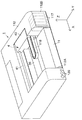
図1に示すのは、本実施形態に係る画像形成装置としてのプリンタを示す斜視図である。
図1に示すように、プリンタ1は、高さ方向であるZ軸方向に薄型のプリンタである。また、プリンタ1は、四角箱状の本体112を有しており、本体112の中央領域には、キャリッジ40が、図1における左右方向X(主走査方向)に沿って延びるように架設されたキャリッジガイド軸41に案内されて、主走査方向に往復移動自在に設けられている。
Hereinafter, embodiments of the present invention will be described with reference to the drawings.
FIG. 1 is a perspective view showing a printer as an image forming apparatus according to the present embodiment.
As shown in FIG. 1, the
図1に示すように、本体112の中央領域にはキャリッジ40と対向する下側位置に、長尺板状の紙案内前39がその長手方向が主走査方向Xと平行となる状態で配置されている。プリンタ1の前面(図1における手前側の面)下部には、給紙用の用紙カセット11が、前面側が開口するように本体112に形成された凹状の被装着部112Aに挿抜可能な状態で装着(挿入)されている。また、本体112の右端部前面を覆っているカバー112Bの内側には、複数個のインクカートリッジ117が装填されている。
As shown in FIG. 1, in the central region of the
各インクカートリッジ117のインクは、フレキシブル配線板118に付設された図示しない複数本のインク供給チューブを通じてキャリッジ40にそれぞれ供給され、キャリッジ40の下部に設けられた記録ヘッド42(図2に示す)からインク滴が噴射(吐出)される。なお、記録ヘッド42には、インクを噴射させるための圧力をインクに付与する加圧素子(圧電素子、静電素子、発熱素子等)がノズル毎に内蔵され、加圧素子に所定の電圧が印加されることで対応するノズルからインク滴が噴射(吐出)される構成となっている。
The ink of each
印刷時は、用紙カセット11から給紙されて紙案内前39上に位置する用紙Pに対して、キャリッジ40と共に主走査方向へ移動する過程の記録ヘッド42からインク滴が噴射されることにより、1ライン分の印刷が施される。こうしてキャリッジ40の一走査による印字動作と、次行までの用紙搬送動作とが交互に繰り返されることにより、用紙Pに対する印刷が進められる。また、本体112の左端前面下部には、電源スイッチを含む各種の操作スイッチ120が設けられている。
At the time of printing, ink droplets are ejected from the
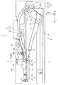
以下、図2を参照しながらプリンタ1の全体構成について概説する。プリンタ1は、装置底部に給送装置2を備え、当該給送装置2から記録用紙Pを1枚ずつ給送し、記録手段4においてインクジェット記録を行い、装置前方側(図2において左側)に設けられた図示しない排紙スタッカへ向けて排出される構成を備えている。
The overall configuration of the
給送装置2は、用紙カセット11と、ピックアップローラ16と、ガイドローラ20と、分離手段21と、を備えている。複数枚の用紙Pを積層状態で収容可能な用紙カセット11は、給送装置2の装置本体に対し、装置前方側から装着及び取り外し可能に構成されており、PF(用紙送り)モータ(図示せず)によって回転駆動されるピックアップローラ16は、揺動軸18を中心に揺動する揺動部材17に設けられ、用紙カセット11に収容された用紙と接して回転することにより、当該最上位の用紙Pを用紙カセット11から送り出す。
The feeding device 2 includes a
用紙カセット11に収容された用紙先端と対向する位置には分離部材12が設けられており、給送されるべき最上位の用紙Pの先端が分離部材12に摺接しつつ下流側に進むことで、次位以降の用紙Pとの第1段階分離が行われる。分離部材12の下流側には自由回転可能なガイドローラ20が設けられ、更にその下流側には、分離ローラ22と駆動ローラ23とを備えて構成された、用紙Pの第2段階分離を行う分離手段21が設けられている。
A separating
分離手段21の下流側には、PFモータ(図示せず)により回転駆動される駆動ローラ26と、駆動ローラ26との間で用紙Pをニップして従動回転するアシストローラ27と、を備えて構成された第1中間送り部25が設けられており、この第1中間送り部25により、用紙Pが更に下流側へと送られる。尚、符号29は、用紙Pが湾曲反転経路を通過する際の(特に用紙後端が通過する際の)通紙負荷を軽減する従動ローラを示している。
On the downstream side of the separating
従動ローラ29の下流側にはPFモータ(図示せず)により回転駆動される駆動ローラ32と、駆動ローラ32との間で用紙Pをニップして従動回転するアシストローラ33と、を備えて構成された第2中間送り部31が設けられており、この第2中間送り部31により、用紙Pが更に下流側へと送られる。
On the downstream side of the driven
第2中間送り部31の下流側には、記録手段4が配置されている。記録手段4は、搬送手段5と、記録ヘッド42と、紙案内前39と、排出手段6と、を備えている。搬送手段5は、PFモータ(図示せず)によって回転駆動される搬送駆動ローラ35と、該搬送駆動ローラ35に圧接して従動回転するよう紙案内上37に軸支される搬送従動ローラ36とを備えて構成され、この搬送手段5により用紙Pが記録ヘッド42と対向する位置に向けて精密送りされる。
The
記録ヘッド42はキャリッジ40の底部に設けられ、当該キャリッジ40は主走査方向(図2の紙面表裏方向)に延びるキャリッジガイド軸41にガイドされながら、CR(キャリッジ)モータ(図示せず)によって主走査方向に往復動する様に駆動される。記録ヘッド42と対向する位置には紙案内前39が設けられ、当該紙案内前39によって、用紙Pと記録ヘッド42との距離が規定されるようになっている。
The
紙案内前39の下流側に設けられた排出手段6は、PFモータ(図示せず)によって回転駆動される排出駆動ローラ44と、当該排出駆動ローラ44に接して従動回転する排出従動ローラ45とを備えて構成され、記録手段4によって記録の行われた用紙Pは、排出手段6により、装置前方側に設けられた図示を省略するスタッカへと排出される。
The discharge means 6 provided on the downstream side of the
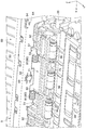
図3に示すのは、本発明の搬送手段のメインフレーム部および後方フレーム部を示す後方斜視図である。また、図4に示すのは、本発明の搬送手段近傍を示す拡大後方断面斜視図である。またさらに、図5に示すのは、本発明の搬送手段近傍を示す拡大側断面図である。また、図6に示すのは、本発明の搬送手段近傍を示す拡大側方断面斜視図である。またさらに、図7に示すのは、本発明の搬送手段近傍を示す拡大前方斜視図である。また、図8に示すのは、本発明の搬送手段の展開斜視図である。 FIG. 3 is a rear perspective view showing the main frame portion and the rear frame portion of the conveying means of the present invention. FIG. 4 is an enlarged rear sectional perspective view showing the vicinity of the conveying means of the present invention. Further, FIG. 5 is an enlarged side sectional view showing the vicinity of the conveying means of the present invention. FIG. 6 is an enlarged side sectional perspective view showing the vicinity of the conveying means of the present invention. Further, FIG. 7 is an enlarged front perspective view showing the vicinity of the conveying means of the present invention. FIG. 8 is a developed perspective view of the conveying means of the present invention.
図3から図8に示す如く、プリンタ1の搬送手段5は、メインフレーム部50と、後方フレーム部60とを有している。このうち、メインフレーム部50は、プリンタ1の基体部58と一体に取り付けられている。また、後方フレーム部60は、メインフレーム部50の後方に配設されている。そして、複数の箇所において、詳しくは後述するようにメインフレーム部50と点接触するように取り付けられている。また、後方フレーム部60は、用紙案内経路の上方の紙案内上37の一部を形成する第1用紙上案内部67を有している。
本実施形態において、メインフレーム部50は、プラスチック等の樹脂で形成されている。一方、後方フレーム部60は、金属板である所謂、板金で形成されている。
As shown in FIGS. 3 to 8, the transport means 5 of the
In the present embodiment, the
またさらに、搬送手段5は、搬送ローラ対70と、従動ローラホルダ71と、従動ローラ軸75と、第1ねじりコイルばね80、80と、第2ねじりコイルばね90、90と、前述したメインフレーム部50と、後方フレーム部60とを有する。このうち、搬送ローラ対70は、搬送用モータの動力によって駆動する搬送駆動ローラ35と、従動回転する搬送従動ローラ36、36…とを有する。搬送従動ローラ36、36…は、従動ローラ軸75に挿通され、従動ローラホルダ71のローラ軸受け部72、72によって回動自在に保持されている。また、搬送従動ローラ36、36…は、第1ねじりコイルばね80、80および第2ねじりコイルばね90、90によって、搬送駆動ローラ側へ付勢されている。
Furthermore, the conveying
尚、本実施例において、一つの従動ローラホルダ71は、3つの搬送従動ローラ36、36…を回動自在に保持している。そして、記録用紙Pの幅方向Xにおいて従動ローラホルダ71は、複数設けられている。また、一つの従動ローラホルダ71に対して、二つの第1ねじりコイルばね80、80と、二つの第2ねじりコイルばね90、90とが設けられている。以下の説明においては、一つの従動ローラホルダ71についての一ユニットについて説明する。
In this embodiment, one driven
第1ねじりコイルばね80、80は、コイル箇所である第1コイル部81、81と、搬送従動ローラ側を付勢する腕である第1ばね腕部82、82と、後方フレーム部60と係合する腕である第2ばね腕部83、83とを有する。
同様に、第2ねじりコイルばね90、90は、コイル箇所である第2コイル部91、91と、搬送従動ローラ側を付勢する腕である第3ばね腕部92、92と、後方フレーム部60と係合する腕である第4ばね腕部93、93とを有する。
The first torsion coil springs 80, 80 are associated with the
Similarly, the second torsion coil springs 90, 90 include
そして、第1ねじりコイルばね80、80の第1コイル部81、81は、メインフレーム部50に形成された第1コイル保持部53、53…によって保持されている。また、第1ばね腕部82、82は、従動ローラ軸75と当接して従動ローラ軸75を介して搬送従動ローラ36、36…を付勢している(図7参照)。一方、第2ばね腕部83、83は、後方フレーム部60に形成されたばね腕係合部66、66…と係合するように構成されている。
The
ここで、第1ばね腕部82、82に付勢力を作用させているので、第2ばね腕部83、83にばね腕係合部66、66…に対して付勢力が作用する。即ち、図5において第1ばね腕部82、82に第1コイル部81、81を支点とする反時計方向へ付勢力が作用しているので、逆方向である時計方向への付勢力が、第2ばね腕部83、83に作用する。
尚、本実施例では、第1ばね腕部82、82が従動ローラ軸75と当接して付勢しているので、第1ねじりコイルばね80、80の力はホルダ軸部73、73およびホルダ軸受け部51、51へ殆ど作用しない。
Here, since the biasing force is applied to the first
In this embodiment, since the first
一方、第2ねじりコイルばね90、90の第2コイル部91、91は、後方フレーム部60に形成された第2コイル保持部63、63…によって保持されている。また、第3ばね腕部92、92は、従動ローラホルダ71と当接して従動ローラホルダ71を介して搬送従動ローラ36、36…を付勢している(図7参照)。一方、第4ばね腕部93、93は、後方フレーム部60のばね腕係合部66、66…と係合するように構成されている。
On the other hand, the
ここで、第3ばね腕部92、92に付勢力を作用させているので、第4ばね腕部93、93にばね腕係合部66、66…に対して付勢力が作用する。即ち、第3ばね腕部92、92に第2コイル部91、91を支点とする回転方向の一方向へ付勢力が作用しているので、逆方向への付勢力が、第4ばね腕部93、93に作用する。
Here, since a biasing force is applied to the third
尚、本実施例では、第2ばね腕部92、92が従動ローラ軸75の近傍と当接して付勢しているので、第2ねじりコイルばね90、90の力はホルダ軸部73、73およびホルダ軸受け部51、51へ殆ど作用しない。
In the present embodiment, since the second
また、従動ローラホルダ71の下面には、用紙Pの上側を案内する第2用紙上案内部74が形成されている。即ち、前述した紙案内上37は、後方フレーム部60の第1用紙上案内部67と、従動ローラホルダ71の第2用紙上案内部74(図5参照)とから構成されている。
またさらに、従動ローラホルダ71には、一対のホルダ軸部73、73(図6および図8参照)が形成されている。ホルダ軸部73、73は、メインフレーム部50にJ字状に形成された一対のホルダ軸受け部51、51によって回動自在に保持されている。従って、従動ローラホルダ71は、ホルダ軸部73、73を支点に揺動することができる。
A second paper
Furthermore, the driven
具体的には、厚みにある用紙を搬送する場合、従動ローラホルダ71が搬送従動ローラ36、36…と共に、第1ねじりコイルばね80、80および第2ねじりコイルばね90、90の付勢力に抗してホルダ軸部73、73を支点に図5における時計方向へ揺動する。
即ち、従動ローラホルダ71および搬送従動ローラ36、36…の位置決めは、メインフレーム部50によって行われるように構成されている。そして、第1ねじりコイルばね80、80および第2ねじりコイルばね90、90のばね荷重(付勢力)は、メインフレーム部50と別体の後方フレーム部60が受けるように構成されている。
Specifically, when transporting thick paper, the driven
That is, the positioning of the driven
また、後方フレーム部60には、抜け止め部61、61(図6参照)が設けられている。そして、抜け止め部61、61は、ホルダ軸受け部51、51におけるJ字の解放側において、ホルダ軸部73、73がホルダ軸受け部51、51から抜け出ることを防止することができるように構成されている。
またさらに、後方フレーム部60は、ネジ59、59…によってメインフレーム部50に対して取り付けられている。
Further, the
Still further, the
具体的には、メインフレーム部50には、複数のネジ挿通孔52、52…が設けられている。一方、後方フレーム部60には、複数のネジ挿通孔52、52…と対向する位置に雌ネジ状の複数のネジ孔部62、62…が設けられている。そして、複数のネジ59、59…が、前方であるメインフレーム部側からそれぞれネジ挿通孔52、52…に挿通され、ネジ孔部62、62…にネジ止めされている。
尚、メインフレーム部50のネジ挿通孔52、52…近傍は、切り込みがあり、ネジ挿通孔52、52…近傍において弾性変形可能に設けられている。即ち、クッション作用を有している。
Specifically, the
In the vicinity of the screw insertion holes 52, 52... Of the
ここで、後方フレーム部60には、第1凸部64、64と、第2凸部65、65…とが設けられている(図8参照)。一方、メインフレーム部50には、係合孔部54、54が設けられている。そして、第1凸部64、64は、係合孔部54、54と係合するように構成されている。該係合によって、メインフレーム部50および後方フレーム部60のX軸およびZ軸方向における位置を、相対的に決めることができるように設けられている。
また、複数の第2凸部65、65…は、複数の箇所においてメインフレーム部50と点接触するように設けられている(図5参照)。
ここで、前述したように、ネジ挿通孔52、52…近傍の切り込みによる弾性変形によって、後方フレーム部60は、メインフレーム部50側に引き寄せられ、第2凸部65、65…における点でのみ接触するように構成されている。
尚、第2凸部を、メインフレーム部側に設けてもよいのは勿論である。
Here, the
Further, the plurality of second
Here, as described above, the
Of course, the second convex portion may be provided on the main frame portion side.
従って、メインフレーム部50および後方フレーム部60のY軸方向における位置を、相対的に決めることができる。
また、点接触であるので、前述した第2ばね腕部83、83および第4ばね腕部93、93から受ける力によって、後方フレーム部60が撓んだ場合であっても、メインフレーム部50に影響を及ぼす虞がない。
その結果、メインフレーム部50によって位置決めされる従動ローラホルダ71および搬送従動ローラ36、36…のX軸、Y軸およびZ軸における位置および姿勢を安定させることができる。
Therefore, the positions of the
Further, since it is a point contact, even when the
As a result, it is possible to stabilize the positions and postures of the driven
即ち、前述したように、従動ローラホルダ71および搬送従動ローラ36、36…の位置決めは、メインフレーム部50によって行われるように構成されている。そして、第1ねじりコイルばね80、80および第2ねじりコイルばね90、90のばね荷重(付勢力)は、メインフレーム部50とは別体の後方フレーム部60が受けるように構成されている。さらに言い換えると、メインフレーム部50と、後方フレーム部60とは、位置決めの役割およびばね荷重を受ける役割ごとに分けるため、それぞれ別体に構成されている。
That is, as described above, the positioning of the driven
そして、該構成によって、搬送駆動ローラ35に対する搬送従動ローラ36、36…の位置を精度良く決めることができる。従って、用紙の搬送精度を安定させることができる。メインフレーム部50と後方フレーム部60とを別体に設ける構成は、Z軸方向にメインフレーム部50を広く(長く)設けることが、レイアウト上、制限されるZ軸方向に薄型のプリンタ1に特に有効である。
With this configuration, the positions of the transport driven
ここで、メインフレーム部50は、第1ねじりコイルばね80、80および第2ねじりコイルばね90、90の付勢力を直接受けない構成である。従って、メインフレーム部50を、金属である所謂、板金ではなく、プラスチック等の樹脂によって形成することができる。係る場合、板金で形成した場合と比較して軽量化をすることができる。
尚、上記実施例では、第1ねじりコイルばね80、80の第1コイル部81、81は、メインフレーム部50の第1コイル保持部53、53…によって保持されるように構成したが、第2ねじりコイルばね90、90の第2コイル部91、91と同様、後方フレーム部60に保持されるように構成してもよい。係る場合、第1ねじりコイルばね80、80および第2ねじりコイルばね90、90の付勢力が間接的にメインフレーム部50に作用することを、より一層、低減することができる。
Here, the
In the above embodiment, the
また、前述したように紙案内上37は、後方フレーム部60の第1用紙上案内部67と、従動ローラホルダ71の第2用紙上案内部74(図5参照)とから構成されている。ここで、紙案内上37の一部である第2用紙上案内部74のみが、ホルダ軸部73、73を支点に揺動する。従って、仮に第1用紙上案内部および第2用紙上案内部の紙案内上が一体に揺動する構成とした場合と比較して、Z軸方向における部材の変位量を小さくすることができる。その結果、Z軸方向により薄くプリンタ1を構成することができる。Z軸方向に薄型のプリンタ1に特に有効である。
またさらに、ネジ59、59…によるネジ止めの位置および第2凸部65、65…による点接触の位置は、幅方向において、第1ねじりコイルばね80および第2ねじりコイルばね90が設けられていない箇所に構成されている。従って、後方フレーム部60が撓んだ場合であっても、メインフレーム部50には殆ど影響を与えることがない。
Further, as described above, the
Further, the first
本実施形態の搬送装置としての搬送手段5は、搬送駆動ローラ35と搬送従動ローラ36、36…とを有し、被搬送媒体の一例である記録用紙Pを搬送方向下流側へ送る搬送ローラ対70と、搬送従動ローラ36、36…を回動自在に保持する従動ローラホルダ71と、従動ローラホルダ71を揺動自在に支持する支持部材としてのメインフレーム部50と、搬送従動ローラ36、36…が搬送駆動ローラ35へ接近する方向へ、弾性変形によって搬送従動ローラ36、36…に対して荷重を付与する荷重付与弾性部材の一例である第1ねじりコイルばね80、80および第2ねじりコイルばね90、90と、メインフレーム部50と別個に設けられ、第1ねじりコイルばね80、80および第2ねじりコイルばね90、90と係合し前記荷重を支える係合部材としての後方フレーム部60と、を備えていることを特徴とする。
The conveying means 5 as the conveying device of the present embodiment includes a conveying driving
また、本実施形態において、メインフレーム部50は、樹脂によって形成されていることを特徴とする。
またさらに、本実施形態において、前記荷重付与弾性部材は、複数の第1ねじりコイルばね80、80および第2ねじりコイルばね90、90であり、該複数の第1ねじりコイルばね80、80および第2ねじりコイルばね90、90の一端側である第1ばね腕部82、82および第3ばね腕部92、92は、従動ローラホルダ71における揺動支点であるホルダ軸部73、73を基準とした搬送従動ローラ側と係合し、他端側である第2ばね腕部83、83および第4ばね腕部93、93は、後方フレーム部60と係合する構成であることを特徴とする。
In the present embodiment, the
Furthermore, in the present embodiment, the load applying elastic members are a plurality of first torsion coil springs 80 and 80 and second torsion coil springs 90 and 90, and the plurality of first torsion coil springs 80 and 80 and The first
また、本実施形態において、後方フレーム部60およびメインフレーム部50の少なくとも一方に凸部としての第2凸部65、65…が形成され、第2凸部65、65…によって、後方フレーム部60とメインフレーム部50とが点接触する構成であることを特徴とする。
本実施形態の記録装置であるプリンタ1は、載置された被記録媒体の一例である記録用紙Pをピックアップして給送する給送部としての給送装置2と、給送された記録用紙Pを搬送方向下流側へ搬送する搬送部としての搬送手段5と、搬送された記録用紙Pに対して記録ヘッド42により記録を実行する記録部としての記録手段4と、を備えていることを特徴とする。
In the present embodiment, second
A
尚、本発明は上記実施例に限定されることなく、特許請求の範囲に記載した発明の範囲内で、種々の変形が可能であり、それらも本発明の範囲内に含まれるものであることは言うまでもない。 The present invention is not limited to the above-described embodiments, and various modifications can be made within the scope of the invention described in the claims, and these are also included in the scope of the present invention. Needless to say.
1 インクジェットプリンタ、2 給送装置、4 記録手段、5 搬送手段、
6 排出手段、11 用紙カセット、12 分離部材、16 ピックアップローラ、
17 揺動部材、18 揺動軸、20 ガイドローラ、21 分離手段、
22 分離ローラ、23 駆動ローラ、25 第1中間送り部、26 駆動ローラ、
27 アシストローラ、29 従動ローラ、31 第2中間送り部、32 駆動ローラ、
33 アシストローラ、35 搬送駆動ローラ、36 搬送従動ローラ、
37 紙案内上、39 紙案内前、40 キャリッジ、41 キャリッジガイド軸、
42 記録ヘッド、44 排出駆動ローラ、45 排出従動ローラ、
50 メインフレーム部、51 ホルダ軸受け部、52 ネジ挿通孔、
53 第1コイル保持部、54 係合孔部、58 基体部、59 ネジ、
60 後方フレーム部、61 抜け止め部、62 ネジ孔部、63 第2コイル保持部、
64 第1凸部、65 第2凸部、66 ばね腕係合部、67 第1用紙上案内部、
70 搬送ローラ対、71 従動ローラホルダ、72 ローラ軸受け部、
73 ホルダ軸部、74 第2用紙上案内部、75 従動ローラ軸、
80 第1ねじりコイルばね、81 第1コイル部、82 第1ばね腕部、
83 第2ばね腕部、90 第2ねじりコイルばね、91 第2コイル部、
92 第3ばね腕部、93 第4ばね腕部、112 本体、112A 被装着部、
112B カバー、117 インクカートリッジ、118 フレキシブル配線板、
120 操作スイッチ、P 記録用紙、X 幅方向、Y 送り方向、Z 高さ方向
1 ink jet printer, 2 feeding device, 4 recording means, 5 conveying means,
6 discharging means, 11 paper cassette, 12 separating member, 16 pickup roller,
17 oscillating member, 18 oscillating shaft, 20 guide roller, 21 separating means,
22 Separating roller, 23 Driving roller, 25 First intermediate feeding section, 26 Driving roller,
27 assist roller, 29 driven roller, 31 second intermediate feed section, 32 drive roller,
33 Assist roller, 35 Conveyance drive roller, 36 Conveyance driven roller,
37 on paper guide, 39 before paper guide, 40 carriage, 41 carriage guide shaft,
42 recording head, 44 discharge drive roller, 45 discharge driven roller,
50 main frame part, 51 holder bearing part, 52 screw insertion hole,
53 1st coil holding part, 54 engagement hole part, 58 base part, 59 screw,
60 rear frame part, 61 retaining part, 62 screw hole part, 63 second coil holding part,
64 1st convex part, 65 2nd convex part, 66 Spring arm engaging part, 67 1st on-paper guide part,
70 pair of conveying rollers, 71 driven roller holder, 72 roller bearing,
73 Holder shaft portion, 74 Second paper upper guide portion, 75 Driven roller shaft,
80 1st torsion coil spring, 81 1st coil part, 82 1st spring arm part,
83 second spring arm part, 90 second torsion coil spring, 91 second coil part,
92 third spring arm portion, 93 fourth spring arm portion, 112 body, 112A attached portion,
112B cover, 117 ink cartridge, 118 flexible wiring board,
120 Operation switch, P recording paper, X width direction, Y feed direction, Z height direction
Claims (5)
前記搬送従動ローラを回動自在に保持する従動ローラホルダと、
該従動ローラホルダを揺動自在に支持する支持部材と、
前記搬送従動ローラが前記搬送駆動ローラへ接近する方向へ、弾性変形によって前記搬送従動ローラに対して荷重を付与する荷重付与弾性部材と、
前記支持部材と別個に設けられ、前記荷重付与弾性部材と係合し前記荷重を支える係合部材と、を備える搬送装置。 A conveyance roller pair having a conveyance driving roller and a conveyance driven roller, and conveying a medium to be conveyed downstream in the conveyance direction;
A driven roller holder for rotatably holding the transport driven roller;
A support member for swingably supporting the driven roller holder;
A load application elastic member that applies a load to the conveyance driven roller by elastic deformation in a direction in which the conveyance driven roller approaches the conveyance driving roller;
An engaging member provided separately from the support member, and engaging with the load applying elastic member to support the load.
該複数のねじりコイルばねの一端側は、前記従動ローラホルダにおける揺動支点を基準とした前記搬送従動ローラ側と係合し、
他端側は、前記係合部材と係合する構成である搬送装置。 The conveying apparatus according to claim 1 or 2, wherein the load applying elastic member is a plurality of torsion coil springs.
One end side of the plurality of torsion coil springs is engaged with the conveying driven roller side with reference to a swing fulcrum in the driven roller holder,
The other end side is a transport device configured to engage with the engaging member.
該凸部によって、前記係合部材と前記支持部材とが点接触する構成である搬送装置。 In the conveyance device according to any one of claims 1 to 3, a convex portion is formed on at least one of the engagement member and the support member,
The conveying apparatus which is the structure which the said engaging member and the said supporting member make point contact by this convex part.
給送された被記録媒体を搬送方向下流側へ搬送する搬送部と、
搬送された被記録媒体に対して記録ヘッドにより記録を実行する記録部と、を備えた記録装置であって、
前記搬送部は、請求項1乃至4のいずれか1項に記載された前記搬送装置を備える記録装置。 A feeding unit that picks up and feeds a recording medium placed thereon;
A transport unit for transporting the fed recording medium downstream in the transport direction;
A recording unit that performs recording on a conveyed recording medium by a recording head,
The recording apparatus including the conveyance device according to any one of claims 1 to 4, wherein the conveyance unit.
Priority Applications (2)
| Application Number | Priority Date | Filing Date | Title |
|---|---|---|---|
| JP2008173946A JP5212626B2 (en) | 2008-07-02 | 2008-07-02 | Conveying device, recording device |
| US12/496,427 US8025292B2 (en) | 2008-07-02 | 2009-07-01 | Transport apparatus and recording apparatus |
Applications Claiming Priority (1)
| Application Number | Priority Date | Filing Date | Title |
|---|---|---|---|
| JP2008173946A JP5212626B2 (en) | 2008-07-02 | 2008-07-02 | Conveying device, recording device |
Publications (2)
| Publication Number | Publication Date |
|---|---|
| JP2010013222A true JP2010013222A (en) | 2010-01-21 |
| JP5212626B2 JP5212626B2 (en) | 2013-06-19 |
Family
ID=41463759
Family Applications (1)
| Application Number | Title | Priority Date | Filing Date |
|---|---|---|---|
| JP2008173946A Expired - Fee Related JP5212626B2 (en) | 2008-07-02 | 2008-07-02 | Conveying device, recording device |
Country Status (2)
| Country | Link |
|---|---|
| US (1) | US8025292B2 (en) |
| JP (1) | JP5212626B2 (en) |
Cited By (4)
| Publication number | Priority date | Publication date | Assignee | Title |
|---|---|---|---|---|
| CN102189834A (en) * | 2010-03-12 | 2011-09-21 | 精工爱普生株式会社 | Feeding device and recording device |
| JP2019127388A (en) * | 2018-01-26 | 2019-08-01 | キヤノン株式会社 | Inkjet recording device and adjustment method |
| US10369824B2 (en) | 2017-05-26 | 2019-08-06 | Seiko Epson Corporation | Transport apparatus and printing apparatus |
| CN111746213A (en) * | 2019-03-27 | 2020-10-09 | 本田技研工业株式会社 | Electric suspension device |
Families Citing this family (6)
| Publication number | Priority date | Publication date | Assignee | Title |
|---|---|---|---|---|
| JP5240243B2 (en) * | 2010-06-17 | 2013-07-17 | ブラザー工業株式会社 | Image recording device |
| JP4998600B2 (en) * | 2010-06-17 | 2012-08-15 | ブラザー工業株式会社 | Image recording device |
| US8262079B2 (en) * | 2010-09-27 | 2012-09-11 | Brother Kogyo Kabushiki Kaisha | Image recording apparatus with sheet conveyance path |
| JP5724358B2 (en) * | 2010-12-17 | 2015-05-27 | 富士ゼロックス株式会社 | Conveying apparatus and image forming apparatus |
| CN102173348B (en) * | 2010-12-20 | 2015-04-22 | 山东新北洋信息技术股份有限公司 | Laminated medium aligning mechanism and processing unit provided with same |
| JP5915080B2 (en) * | 2011-10-28 | 2016-05-11 | ブラザー工業株式会社 | Image forming apparatus |
Citations (4)
| Publication number | Priority date | Publication date | Assignee | Title |
|---|---|---|---|---|
| JP2001341884A (en) * | 2000-05-31 | 2001-12-11 | Seiko Epson Corp | Roller energizing device in recording device, and recording device having the same |
| JP2003312886A (en) * | 2002-04-24 | 2003-11-06 | Seiko Instruments Inc | Paper feeding mechanism for ink jet recording device |
| JP2007197208A (en) * | 2006-01-30 | 2007-08-09 | Sato Corp | Carrying roller pressure regulator |
| JP2008074612A (en) * | 2006-09-25 | 2008-04-03 | Seiko Epson Corp | Recording medium conveying device, recording device, and liquid injection device |
Family Cites Families (5)
| Publication number | Priority date | Publication date | Assignee | Title |
|---|---|---|---|---|
| JP3109924B2 (en) * | 1992-10-29 | 2000-11-20 | キヤノン株式会社 | Sheet transport device |
| JPH10120234A (en) * | 1996-10-22 | 1998-05-12 | Seiko Epson Corp | Sheet conveying device |
| JP2004123341A (en) * | 2002-10-04 | 2004-04-22 | Ricoh Co Ltd | Feeder and image forming device having the same |
| JP2005022128A (en) * | 2003-06-30 | 2005-01-27 | Brother Ind Ltd | Recording medium conveying device and image forming apparatus using the same |
| JP2008074605A (en) | 2006-09-25 | 2008-04-03 | Seiko Epson Corp | Medium carrying device |
-
2008
- 2008-07-02 JP JP2008173946A patent/JP5212626B2/en not_active Expired - Fee Related
-
2009
- 2009-07-01 US US12/496,427 patent/US8025292B2/en not_active Expired - Fee Related
Patent Citations (4)
| Publication number | Priority date | Publication date | Assignee | Title |
|---|---|---|---|---|
| JP2001341884A (en) * | 2000-05-31 | 2001-12-11 | Seiko Epson Corp | Roller energizing device in recording device, and recording device having the same |
| JP2003312886A (en) * | 2002-04-24 | 2003-11-06 | Seiko Instruments Inc | Paper feeding mechanism for ink jet recording device |
| JP2007197208A (en) * | 2006-01-30 | 2007-08-09 | Sato Corp | Carrying roller pressure regulator |
| JP2008074612A (en) * | 2006-09-25 | 2008-04-03 | Seiko Epson Corp | Recording medium conveying device, recording device, and liquid injection device |
Cited By (5)
| Publication number | Priority date | Publication date | Assignee | Title |
|---|---|---|---|---|
| CN102189834A (en) * | 2010-03-12 | 2011-09-21 | 精工爱普生株式会社 | Feeding device and recording device |
| US10369824B2 (en) | 2017-05-26 | 2019-08-06 | Seiko Epson Corporation | Transport apparatus and printing apparatus |
| JP2019127388A (en) * | 2018-01-26 | 2019-08-01 | キヤノン株式会社 | Inkjet recording device and adjustment method |
| JP7051462B2 (en) | 2018-01-26 | 2022-04-11 | キヤノン株式会社 | Recording device and adjustment method |
| CN111746213A (en) * | 2019-03-27 | 2020-10-09 | 本田技研工业株式会社 | Electric suspension device |
Also Published As
| Publication number | Publication date |
|---|---|
| JP5212626B2 (en) | 2013-06-19 |
| US20100001461A1 (en) | 2010-01-07 |
| US8025292B2 (en) | 2011-09-27 |
Similar Documents
| Publication | Publication Date | Title |
|---|---|---|
| JP5212626B2 (en) | Conveying device, recording device | |
| US9290021B2 (en) | Inkjet recording apparatus | |
| JP5786681B2 (en) | Inkjet recording device | |
| US8882108B2 (en) | Ink-jet printer | |
| JP5924222B2 (en) | Conveying apparatus and image recording apparatus | |
| JP2005035033A (en) | Inkjet recorder and liquid ejector | |
| JP6458605B2 (en) | Conveying apparatus and image recording apparatus | |
| JP2016044048A (en) | Recording device and sheet feeding device | |
| JP2009249162A (en) | Transporting device and image recording device | |
| JP6142563B2 (en) | Conveying apparatus and image recording apparatus | |
| JP2008074612A (en) | Recording medium conveying device, recording device, and liquid injection device | |
| JP6642050B2 (en) | Transport device and image recording device | |
| US20060071422A1 (en) | Pressure roller plate with force distribution | |
| JP2010046873A (en) | Recording device | |
| US9227804B2 (en) | Recording apparatus | |
| JP5206942B2 (en) | Medium feeding device, recording device, and method for continuously controlling separation of feeding driven roller | |
| JP2009113432A (en) | Inkjet printer | |
| JP6119539B2 (en) | Inkjet recording device | |
| JP6918534B2 (en) | Sheet separator and printing device | |
| JP4289684B2 (en) | Image forming apparatus | |
| JP5024534B2 (en) | Feeding device, recording device | |
| JP6186740B2 (en) | Image recording device | |
| JP2008044752A (en) | Recording medium conveying device, recording device, and liquid injection device | |
| JP2020011448A (en) | Height adjustment mechanism and image formation device including the same | |
| JP2010030224A (en) | Recording medium carrying apparatus and recorder |
Legal Events
| Date | Code | Title | Description |
|---|---|---|---|
| A621 | Written request for application examination |
Free format text: JAPANESE INTERMEDIATE CODE: A621 Effective date: 20110615 |
|
| A977 | Report on retrieval |
Free format text: JAPANESE INTERMEDIATE CODE: A971007 Effective date: 20120808 |
|
| A131 | Notification of reasons for refusal |
Free format text: JAPANESE INTERMEDIATE CODE: A131 Effective date: 20120815 |
|
| A521 | Request for written amendment filed |
Free format text: JAPANESE INTERMEDIATE CODE: A523 Effective date: 20121011 |
|
| TRDD | Decision of grant or rejection written | ||
| A01 | Written decision to grant a patent or to grant a registration (utility model) |
Free format text: JAPANESE INTERMEDIATE CODE: A01 Effective date: 20130130 |
|
| A61 | First payment of annual fees (during grant procedure) |
Free format text: JAPANESE INTERMEDIATE CODE: A61 Effective date: 20130212 |
|
| R150 | Certificate of patent or registration of utility model |
Ref document number: 5212626 Country of ref document: JP Free format text: JAPANESE INTERMEDIATE CODE: R150 Free format text: JAPANESE INTERMEDIATE CODE: R150 |
|
| FPAY | Renewal fee payment (event date is renewal date of database) |
Free format text: PAYMENT UNTIL: 20160308 Year of fee payment: 3 |
|
| S531 | Written request for registration of change of domicile |
Free format text: JAPANESE INTERMEDIATE CODE: R313531 |
|
| R350 | Written notification of registration of transfer |
Free format text: JAPANESE INTERMEDIATE CODE: R350 |
|
| LAPS | Cancellation because of no payment of annual fees |