JP2010012931A - Pneumatic tire - Google Patents
Pneumatic tire Download PDFInfo
- Publication number
- JP2010012931A JP2010012931A JP2008174656A JP2008174656A JP2010012931A JP 2010012931 A JP2010012931 A JP 2010012931A JP 2008174656 A JP2008174656 A JP 2008174656A JP 2008174656 A JP2008174656 A JP 2008174656A JP 2010012931 A JP2010012931 A JP 2010012931A
- Authority
- JP
- Japan
- Prior art keywords
- groove
- circumferential
- tread
- pneumatic tire
- along
- Prior art date
- Legal status (The legal status is an assumption and is not a legal conclusion. Google has not performed a legal analysis and makes no representation as to the accuracy of the status listed.)
- Granted
Links
Images


Classifications
-
- B—PERFORMING OPERATIONS; TRANSPORTING
- B60—VEHICLES IN GENERAL
- B60C—VEHICLE TYRES; TYRE INFLATION; TYRE CHANGING; CONNECTING VALVES TO INFLATABLE ELASTIC BODIES IN GENERAL; DEVICES OR ARRANGEMENTS RELATED TO TYRES
- B60C11/00—Tyre tread bands; Tread patterns; Anti-skid inserts
- B60C11/03—Tread patterns
- B60C11/12—Tread patterns characterised by the use of narrow slits or incisions, e.g. sipes
- B60C11/1236—Tread patterns characterised by the use of narrow slits or incisions, e.g. sipes with special arrangements in the tread pattern
- B60C11/125—Tread patterns characterised by the use of narrow slits or incisions, e.g. sipes with special arrangements in the tread pattern arranged at the groove bottom
-
- B—PERFORMING OPERATIONS; TRANSPORTING
- B60—VEHICLES IN GENERAL
- B60C—VEHICLE TYRES; TYRE INFLATION; TYRE CHANGING; CONNECTING VALVES TO INFLATABLE ELASTIC BODIES IN GENERAL; DEVICES OR ARRANGEMENTS RELATED TO TYRES
- B60C11/00—Tyre tread bands; Tread patterns; Anti-skid inserts
- B60C11/03—Tread patterns
- B60C11/0304—Asymmetric patterns
-
- B—PERFORMING OPERATIONS; TRANSPORTING
- B60—VEHICLES IN GENERAL
- B60C—VEHICLE TYRES; TYRE INFLATION; TYRE CHANGING; CONNECTING VALVES TO INFLATABLE ELASTIC BODIES IN GENERAL; DEVICES OR ARRANGEMENTS RELATED TO TYRES
- B60C11/00—Tyre tread bands; Tread patterns; Anti-skid inserts
- B60C11/03—Tread patterns
- B60C11/0306—Patterns comprising block rows or discontinuous ribs
- B60C11/0309—Patterns comprising block rows or discontinuous ribs further characterised by the groove cross-section
-
- B—PERFORMING OPERATIONS; TRANSPORTING
- B60—VEHICLES IN GENERAL
- B60C—VEHICLE TYRES; TYRE INFLATION; TYRE CHANGING; CONNECTING VALVES TO INFLATABLE ELASTIC BODIES IN GENERAL; DEVICES OR ARRANGEMENTS RELATED TO TYRES
- B60C11/00—Tyre tread bands; Tread patterns; Anti-skid inserts
- B60C11/03—Tread patterns
- B60C11/04—Tread patterns in which the raised area of the pattern consists only of continuous circumferential ribs, e.g. zig-zag
- B60C11/042—Tread patterns in which the raised area of the pattern consists only of continuous circumferential ribs, e.g. zig-zag further characterised by the groove cross-section
-
- B—PERFORMING OPERATIONS; TRANSPORTING
- B60—VEHICLES IN GENERAL
- B60C—VEHICLE TYRES; TYRE INFLATION; TYRE CHANGING; CONNECTING VALVES TO INFLATABLE ELASTIC BODIES IN GENERAL; DEVICES OR ARRANGEMENTS RELATED TO TYRES
- B60C11/00—Tyre tread bands; Tread patterns; Anti-skid inserts
- B60C11/03—Tread patterns
- B60C2011/0337—Tread patterns characterised by particular design features of the pattern
- B60C2011/0339—Grooves
- B60C2011/0381—Blind or isolated grooves
-
- B—PERFORMING OPERATIONS; TRANSPORTING
- B60—VEHICLES IN GENERAL
- B60C—VEHICLE TYRES; TYRE INFLATION; TYRE CHANGING; CONNECTING VALVES TO INFLATABLE ELASTIC BODIES IN GENERAL; DEVICES OR ARRANGEMENTS RELATED TO TYRES
- B60C11/00—Tyre tread bands; Tread patterns; Anti-skid inserts
- B60C11/03—Tread patterns
- B60C2011/0337—Tread patterns characterised by particular design features of the pattern
- B60C2011/0386—Continuous ribs
- B60C2011/0388—Continuous ribs provided at the equatorial plane
-
- B—PERFORMING OPERATIONS; TRANSPORTING
- B60—VEHICLES IN GENERAL
- B60C—VEHICLE TYRES; TYRE INFLATION; TYRE CHANGING; CONNECTING VALVES TO INFLATABLE ELASTIC BODIES IN GENERAL; DEVICES OR ARRANGEMENTS RELATED TO TYRES
- B60C11/00—Tyre tread bands; Tread patterns; Anti-skid inserts
- B60C11/03—Tread patterns
- B60C11/12—Tread patterns characterised by the use of narrow slits or incisions, e.g. sipes
- B60C11/1204—Tread patterns characterised by the use of narrow slits or incisions, e.g. sipes with special shape of the sipe
- B60C2011/1209—Tread patterns characterised by the use of narrow slits or incisions, e.g. sipes with special shape of the sipe straight at the tread surface
-
- B—PERFORMING OPERATIONS; TRANSPORTING
- B60—VEHICLES IN GENERAL
- B60C—VEHICLE TYRES; TYRE INFLATION; TYRE CHANGING; CONNECTING VALVES TO INFLATABLE ELASTIC BODIES IN GENERAL; DEVICES OR ARRANGEMENTS RELATED TO TYRES
- B60C11/00—Tyre tread bands; Tread patterns; Anti-skid inserts
- B60C11/03—Tread patterns
- B60C11/13—Tread patterns characterised by the groove cross-section, e.g. for buttressing or preventing stone-trapping
- B60C11/1307—Tread patterns characterised by the groove cross-section, e.g. for buttressing or preventing stone-trapping with special features of the groove walls
- B60C2011/133—Tread patterns characterised by the groove cross-section, e.g. for buttressing or preventing stone-trapping with special features of the groove walls comprising recesses
-
- B—PERFORMING OPERATIONS; TRANSPORTING
- B60—VEHICLES IN GENERAL
- B60C—VEHICLE TYRES; TYRE INFLATION; TYRE CHANGING; CONNECTING VALVES TO INFLATABLE ELASTIC BODIES IN GENERAL; DEVICES OR ARRANGEMENTS RELATED TO TYRES
- B60C11/00—Tyre tread bands; Tread patterns; Anti-skid inserts
- B60C11/03—Tread patterns
- B60C11/13—Tread patterns characterised by the groove cross-section, e.g. for buttressing or preventing stone-trapping
- B60C11/1307—Tread patterns characterised by the groove cross-section, e.g. for buttressing or preventing stone-trapping with special features of the groove walls
- B60C2011/1338—Tread patterns characterised by the groove cross-section, e.g. for buttressing or preventing stone-trapping with special features of the groove walls comprising protrusions
-
- B—PERFORMING OPERATIONS; TRANSPORTING
- B60—VEHICLES IN GENERAL
- B60C—VEHICLE TYRES; TYRE INFLATION; TYRE CHANGING; CONNECTING VALVES TO INFLATABLE ELASTIC BODIES IN GENERAL; DEVICES OR ARRANGEMENTS RELATED TO TYRES
- B60C11/00—Tyre tread bands; Tread patterns; Anti-skid inserts
- B60C11/03—Tread patterns
- B60C11/13—Tread patterns characterised by the groove cross-section, e.g. for buttressing or preventing stone-trapping
- B60C11/1353—Tread patterns characterised by the groove cross-section, e.g. for buttressing or preventing stone-trapping with special features of the groove bottom
- B60C2011/1361—Tread patterns characterised by the groove cross-section, e.g. for buttressing or preventing stone-trapping with special features of the groove bottom with protrusions extending from the groove bottom
Landscapes
- Engineering & Computer Science (AREA)
- Mechanical Engineering (AREA)
- Tires In General (AREA)
Abstract
Description
本発明は、タイヤ周方向に沿って延びる周方向溝が形成された空気入りタイヤに関し、特に、氷雪路向けの空気入りタイヤに関する。 The present invention relates to a pneumatic tire in which circumferential grooves extending along the tire circumferential direction are formed, and more particularly to a pneumatic tire for icy and snowy roads.
従来、氷雪路向けに製造された空気入りタイヤ、いわゆるスタッドレスタイヤにおいて、タイヤ周方向に沿った溝幅が広い(例えば、7mm以上)周方向溝と、トレッド幅方向に伸びるサイプとを形成する構造が知られている(例えば、特許文献1)。 Conventionally, in a pneumatic tire manufactured for icy and snowy roads, a so-called studless tire, a structure in which a circumferential groove having a wide groove width (for example, 7 mm or more) along the tire circumferential direction and a sipe extending in the tread width direction are formed. Is known (for example, Patent Document 1).
このような空気入りタイヤによれば、路面とトレッド踏面との間に入り込んだ雨水やシャーベット状の雪などの排水性向上と、氷雪路における横滑りの抑制とを実現することができる。
しかしながら、上述した従来の空気入りタイヤには、次のような問題があった。すなわち、溝幅が広い周方向溝が形成されると、トレッド踏面を構成する陸部(ブロック)の面積やサイプの数などが減少する。このため、排水性向上や氷雪路における横滑りの抑制は図られるものの、氷雪路における駆動性能や制動性能を向上させることはできない問題があった。 However, the conventional pneumatic tire described above has the following problems. That is, when a circumferential groove with a wide groove width is formed, the area of the land portion (block) constituting the tread surface, the number of sipes, and the like are reduced. For this reason, although drainage improvement and suppression of skid on an icy snow road can be achieved, there has been a problem that driving performance and braking performance on an icy snow road cannot be improved.
そこで、本発明は、このような状況に鑑みてなされたものであり、排水性向上や氷雪路における横滑りの抑制を図りつつ、氷雪路における駆動性能や制動性能をさらに向上させた空気入りタイヤを提供することを目的とする。 Therefore, the present invention has been made in view of such a situation, and a pneumatic tire that further improves driving performance and braking performance on an icy snow road while improving drainage and suppressing side slip on the icy snow road. The purpose is to provide.
上述した状況を解決するため、本発明は、次のような特徴を有している。まず、本発明の第1の特徴において、空気入りタイヤ(例えば、空気入りタイヤ1A)は、路面と接するトレッド踏面(トレッド踏面10)を構成する陸部(陸部20)によって、タイヤ周方向に沿って延びる周方向溝(例えば、周方向溝32)が形成される。周方向溝内には、周方向溝の溝底(溝底32a)の表面が平滑な平滑溝部(平滑溝部60)と、周方向溝の溝底よりもトレッド踏面側に隆起する溝内陸部(溝内陸部70)とが形成される。溝内陸部には、トレッド幅方向に沿って延びる複数の細溝(細溝80)が形成される。周方向溝のトレッド幅方向に沿った幅(太溝幅W1)は、トレッド踏面のトレッド幅方向に沿った幅(トレッド幅TW)に対して5〜30%である。
In order to solve the above situation, the present invention has the following features. First, in the first feature of the present invention, a pneumatic tire (for example, a
かかる特徴によれば、周方向溝内には、平滑溝部が形成される。太溝幅は、トレッド幅に対して5〜30%である。これによれば、周方向溝に入り込んだ雨水などが排出されやすくなるため、排水性向上を図ることができる。また、周方向溝に雪がしっかり入り込むため、氷雪路における横滑りを抑制することができる。 According to this feature, a smooth groove portion is formed in the circumferential groove. The thick groove width is 5 to 30% with respect to the tread width. According to this, rainwater or the like that enters the circumferential groove is easily discharged, so that drainage can be improved. Moreover, since snow enters the circumferential groove firmly, skidding on an icy snow road can be suppressed.
また、周方向溝内には、溝内陸部が形成される。溝内陸部には、トレッド幅方向に沿って延びる複数の細溝が形成されている。これによれば、周方向溝に入り込んだ雪に細溝が引っかかる効果(いわゆる、エッジ効果)が増大するため、氷雪路における駆動性能や制動性能をさらに向上させることができる。 A groove inland portion is formed in the circumferential groove. A plurality of narrow grooves extending along the tread width direction are formed in the inland portion of the groove. According to this, the effect (so-called edge effect) that the narrow groove is caught by the snow that has entered the circumferential groove increases (so-called edge effect), so that it is possible to further improve the driving performance and braking performance on the icy and snowy road.
その他の特徴において、周方向溝は、複数設けられる。平滑溝部と溝内陸部とが形成された周方向溝は、複数の周方向溝のうち、トレッド幅方向に沿った幅が最も広い。 In other features, a plurality of circumferential grooves are provided. The circumferential groove in which the smooth groove portion and the inland portion of the groove are formed has the widest width along the tread width direction among the plurality of circumferential grooves.
その他の特徴において、陸部のトレッド踏面から溝内陸部の上面部(上面部72)までの溝深さ(第1溝深さD1)は、陸部のトレッド踏面から周方向溝の溝底までの深さ(第2溝深さD2)に対して60〜95%である。 In another feature, the groove depth (first groove depth D1) from the tread surface of the land portion to the upper surface portion (upper surface portion 72) of the inland groove portion is from the tread surface of the land portion to the groove bottom of the circumferential groove. It is 60 to 95% with respect to the depth (second groove depth D2).
その他の特徴において、細溝のタイヤ周方向に沿った幅(細溝幅W2)は、1〜8mmである。 In other features, the width of the narrow groove along the tire circumferential direction (thin groove width W2) is 1 to 8 mm.
その他の特徴において、細溝と、タイヤ赤道面に直交する直線とが成す角度(細溝角度α)は、0〜45度である。 In other features, an angle formed by the narrow groove and a straight line orthogonal to the tire equatorial plane (thin groove angle α) is 0 to 45 degrees.
その他の特徴において、細溝の溝底(溝底81)から溝内陸部の上面部までの深さ(細溝深さD3)は、周方向溝の溝底から溝内陸部の上面部までの高さ(溝内陸部高さH)に対して50〜100%である。 In another feature, the depth from the groove bottom of the narrow groove (groove bottom 81) to the upper surface portion of the inland groove portion (thin groove depth D3) is from the groove bottom of the circumferential groove to the upper surface portion of the groove inland portion. It is 50 to 100% with respect to the height (groove inland height H).
その他の特徴において、溝内陸部と、平滑溝部の逆側に位置する陸部との間には、空隙(空隙90)が生成される。 In other features, a gap (gap 90) is generated between the land in the groove and the land located on the opposite side of the smooth groove.
その他の特徴において、トレッド幅方向及びタイヤ径方向に沿った平滑溝部の断面形状は、タイヤ周方向に沿って一定であるとともに、平滑溝部からタイヤ赤道面までのトレッド幅方向に沿った距離は、タイヤ周方向に沿って一定である。 In other features, the cross-sectional shape of the smooth groove portion along the tread width direction and the tire radial direction is constant along the tire circumferential direction, and the distance along the tread width direction from the smooth groove portion to the tire equatorial plane is It is constant along the tire circumferential direction.
その他の特徴において、陸部の少なくとも一部には、トレッド幅方向に沿って延びるラグ溝が複数形成される。 In other features, a plurality of lug grooves extending along the tread width direction are formed in at least a part of the land portion.
その他の特徴において、細溝は、相互に隣接するラグ溝間において、2〜8本形成される。 In other features, 2 to 8 narrow grooves are formed between the lug grooves adjacent to each other.
その他の特徴において、陸部には細溝からトレッド幅方向に延びる切欠き部(切欠き部85)が形成される。切欠き部のタイヤ周方向に沿った幅(切欠幅W3)は、細溝のタイヤ周方向に沿った幅と略同一である。 In other features, a notch (notch 85) extending from the narrow groove in the tread width direction is formed in the land portion. The width along the tire circumferential direction of the notch (notch width W3) is substantially the same as the width along the tire circumferential direction of the narrow groove.
その他の特徴において、トレッド幅方向及びタイヤ径方向に沿った溝内陸部の断面は、略四角形状である。 In other features, the cross section of the groove inland portion along the tread width direction and the tire radial direction is substantially rectangular.
その他の特徴において、溝内陸部記平滑溝部側に位置する端部に沿って延びる直線(直線L3)は、タイヤ赤道面に対して傾く。 In other features, a straight line (straight line L3) extending along the end located on the smooth groove portion side in the groove is inclined with respect to the tire equatorial plane.
本発明によれば、排水性向上や氷雪路における横滑りの抑制を図りつつ、氷雪路における駆動性能や制動性能をさらに向上させた空気入りタイヤを提供することができる。 ADVANTAGE OF THE INVENTION According to this invention, the pneumatic tire which improved further the drive performance and braking performance in an icy snow road can be provided, aiming at the drainage improvement and suppression of the skid on an icy snow road.
次に、本発明に係る空気入りタイヤの一例について、図面を参照しながら説明する。なお、以下の図面の記載において、同一または類似の部分には、同一又は類似の符号を付している。ただし、図面は模式的なのものであり、各寸法の比率などは現実のものとは異なることを留意すべきである。 Next, an example of a pneumatic tire according to the present invention will be described with reference to the drawings. In the following description of the drawings, the same or similar parts are denoted by the same or similar reference numerals. However, it should be noted that the drawings are schematic and ratios of dimensions are different from actual ones.
したがって、具体的な寸法などは以下の説明を参酌して判断すべきものである。また、図面相互間においても互いの寸法の関係や比率が異なる部分が含まれていることは勿論である。 Accordingly, specific dimensions and the like should be determined in consideration of the following description. Moreover, it is a matter of course that portions having different dimensional relationships and ratios are included between the drawings.
[第1実施形態]
(トレッドパターンの構成)
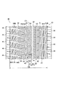
以下において、第1実施形態に係る空気入りタイヤ1Aのトレッドパターン構成について、図面を参照しながら説明する。図1は、第1実施形態に係る空気入りタイヤ1Aのトレッドパターンを示す展開図である。図2は、第1実施形態に係る空気入りタイヤ1Aを示す一部拡大図である。
[First Embodiment]
(Configuration of tread pattern)
Hereinafter, a tread pattern configuration of the
第1実施形態に係る空気入りタイヤ1Aは、ビード部やカーカス層、ベルト層(不図示)を備える一般的なラジアルタイヤである。また、第1実施形態に係る空気入りタイヤ1Aは、タイヤ赤道面CSに対して非対称パターンである。
A
図1及び図2に示すように、空気入りタイヤ1Aでは、路面と接するトレッド踏面10、すなわち、トレッド部表面を構成する陸部20によって、タイヤ周方向に沿って延びる周方向溝30と、トレッド幅方向に沿って伸びるラグ溝40と、周方向溝30及びラグ溝40よりも細いサイプ50とが複数形成されている。
As shown in FIGS. 1 and 2, in the pneumatic tire 1 </ b> A, a
陸部20は、タイヤ周方向及びトレッド幅方向に向かって所定間隔で複数設けられている。陸部20は、図1の右側から左側に向けて、陸部21、陸部22、陸部23、陸部24、陸部25とする。
A plurality of land portions 20 are provided at predetermined intervals in the tire circumferential direction and the tread width direction. The land portion 20 is a
陸部21には、陸部21を分断するラグ溝41と、タイヤ周方向に伸びるサイプ51Aと、トレッド幅方向に伸びるサイプ51Bとが複数形成されている。陸部22には、陸部22を分断するラグ溝42と、トレッド幅方向に伸びるサイプ52とが複数形成されている。
The
陸部23には、ラグ溝42と略平行に伸びるラグ溝43と、トレッド幅方向に伸びるサイプ53とが複数形成されている。ラグ溝43の一方の端部は、後述する周方向溝33に開口し、ラグ溝43の他方の端部は、陸部23内で終結している。すなわち、陸部23は、リブ状に形成されている。
A plurality of
陸部24には、陸部24を分断するラグ溝44Aと、ラグ溝42及びラグ溝43と略平行に伸びるラグ溝44Bと、トレッド幅方向に伸びるサイプ54とが複数形成されている。ラグ溝44Bの一方の端部は、後述する周方向溝33に開口し、ラグ溝43の他方の端部は、陸部24内で終結している。陸部25には、陸部25を分断するラグ溝45と、タイヤ周方向に伸びるサイプ55Aと、トレッド幅方向に伸びるサイプ55Bとが複数形成されている。
A plurality of lug grooves 44 </ b> A that divide the
周方向溝30は、トレッド幅方向に向かって所定の間隔で複数(図面では、4本)設けられている。周方向溝30は、以下において、図1右側から左側に向けて、周方向溝31、周方向溝32、周方向溝33、周方向溝34とする。
A plurality of circumferential grooves 30 (four in the drawing) are provided at predetermined intervals in the tread width direction. In the following, the circumferential grooves 30 are referred to as a
複数の周方向溝30のうちの周方向溝32は、トレッド幅方向に沿った幅が最も広い。周方向溝32のトレッド幅方向に沿った幅(以下、太溝幅W1)は、トレッド踏面のトレッド幅方向に沿った幅(以下、トレッド幅TW)に対して5〜30%である。
Of the plurality of circumferential grooves 30, the
(周方向溝の構成)
次に、上述した周方向溝32の構成について、図面を参照しながら説明する。図3は、第1実施形態に係る周方向溝32の一部斜視図である。図3では、サイプ50が省略されている。図4は、第1実施形態に係る周方向溝32のトレッド幅方向断面図(図3のA−A断面図)である。図5は、第1実施形態に係る周方向溝32のタイヤ周方向断面(図3のB−B断面図)である。
(Configuration of circumferential groove)
Next, the configuration of the
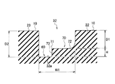
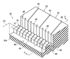
図3〜図5に示すように、周方向溝32内には、周方向溝32の溝底32aの表面が平滑な平滑溝部60と、周方向溝32の溝底32aよりもトレッド踏面10側に隆起する溝内陸部70とが形成されている。
As shown in FIGS. 3 to 5, in the
平滑溝部60は、溝内陸部70よりもタイヤ赤道面CS側に設けられている。トレッド幅方向及びタイヤ径方向に沿った平滑溝部60の断面形状は、タイヤ周方向に沿って一定である(図4参照)とともに、平滑溝部60からタイヤ赤道面CSまでのトレッド幅方向に沿った距離Dは、タイヤ周方向に沿って一定である(図1参照)。
The
溝内陸部70は、陸部22とトレッド幅方向に連続して形成されている。トレッド幅方向及びタイヤ径方向における溝内陸部70の断面は、略四角形状である(図4参照)。具体的には、該断面において、溝内陸部70の上面部72は、トレッド幅方向に沿って延びる。また、該断面において、溝内陸部70の平滑溝部60側に位置する内側端71(端部)から平滑溝部60(周方向溝32の溝底32a)に向かって伸びる溝壁73は、タイヤ径方向に延びる。
The
溝内陸部70の平滑溝部60側に位置する内側端71に沿って延びる直線L1は、タイヤ赤道面CSと略平行である(図3参照)。すなわち、直線L1は、タイヤ周方向に沿って延びている。
A straight line L1 extending along the
陸部22のトレッド踏面10から溝内陸部70の上面部72までの溝深さ(以下、第1溝深さD1)は、陸部23のトレッド踏面から周方向溝32の溝底32aまでの深さ(以下、第2溝深さD2)に対して60〜95%である(図4参照)。
The groove depth from the
溝内陸部70には、陸部22から連続したラグ溝42と、トレッド幅方向に沿って延びる複数の細溝80とが形成されている。細溝80と、タイヤ赤道面CSに直交する直線L2とが成す角度(以下、細溝角度α)は、0〜45度である(図1参照)。
The
細溝80は、相互に隣接するラグ溝42間において、2〜8本(図面では、4本)形成されている。細溝80のタイヤ周方向に沿った幅(以下、細溝幅W2)は、1〜8mmである(図5参照)。
Between the
細溝80の溝底81から溝内陸部70の上面部72までの深さ(以下、細溝深さD3)は、周方向溝32の溝底32aから溝内陸部70の上面部72までの高さ(以下、溝内陸部高さH)に対して50〜100%である(図5参照)。
The depth from the
ここで、溝内陸部70が隣接する陸部22には、細溝80からトレッド幅方向に延びて陸部22内に終結する切欠き部85が形成されている。切欠き部85のタイヤ周方向に沿った幅(以下、切欠幅W3)は、細溝幅W2と略同一である。
Here, a
(作用・効果)
第1実施形態では、周方向溝32内には、平滑溝部60が形成される。太溝幅W1は、トレッド幅TWに対して5〜30%である。これによれば、周方向溝32に入り込んだ雨水などが排出されやすくなるため、排水性向上を図ることができる。また、周方向溝32に雪がしっかり入り込むため、氷雪路における横滑りを抑制することができる。
(Action / Effect)
In the first embodiment, a
また、周方向溝32内には、溝内陸部70が形成される。溝内陸部70には、トレッド幅方向に沿って延びる複数の細溝80が形成されている。これによれば、周方向溝32に入り込んだ雪に細溝80が引っかかる効果(いわゆる、エッジ効果)が増大するため、氷雪路における駆動性能や制動性能をさらに向上させることができる。
A
第1実施形態では、周方向溝32は、複数の周方向溝のうち、太溝幅W1が最も広い。トレッド幅方向及びタイヤ径方向に沿った平滑溝部60の断面形状は、タイヤ周方向に沿って一定であるとともに、平滑溝部60からタイヤ赤道面CSまでのトレッド幅方向に沿った距離Dは、タイヤ周方向に沿って一定である。これによれば、周方向溝32に入り込んだ雨水などが排水されやすくなるため、排水性の低下を抑制することができる。
In the first embodiment, the
第1実施形態では、細溝幅W2は、1〜8mmである。細溝幅W2が1mmよりも大きいことによって、周方向溝32に入り込んだ雪に細溝80が引っかかる効果(いわゆる、エッジ効果)が増大するため、氷雪路における駆動性能や制動性能をさらに向上させることができる。一方、細溝幅W2が8mmよりも小さいことによって、周方向溝32に入り込んだ雨水などの抵抗が増大し過ぎることがないため、排水性の低下を抑制することができる。
In the first embodiment, the narrow groove width W2 is 1 to 8 mm. Since the narrow groove width W2 is larger than 1 mm, the effect of soaking the
第1実施形態では、第1溝深さD1は、第2溝深さD2に対して60〜95%である。第1溝深さD1が第2溝深さD2に対して60%よりも大きいことによって、周方向溝32の体積を減少させ過ぎることがないため、排水性の低下を抑制することができる。一方、第1溝深さD1が第2溝深さD2に対して95%よりも小さいことによって、周方向溝32に入り込んだ雪に細溝80が引っかかる効果(いわゆる、エッジ効果)を確保できるため、氷雪路における駆動性能や制動性能をさらに向上させることができる。
In the first embodiment, the first groove depth D1 is 60 to 95% with respect to the second groove depth D2. Since the first groove depth D1 is larger than 60% with respect to the second groove depth D2, the volume of the
第1実施形態では、細溝角度αは、0〜45度である。細溝角度αが45度よりも小さいことによって、周方向溝32に入り込んだ雪に溝内陸部70や細溝80が引っかかる効果(いわゆる、エッジ効果)が増大するため、氷雪路における駆動性能や制動性能をさらに向上させることができる。
In the first embodiment, the narrow groove angle α is 0 to 45 degrees. Since the narrow groove angle α is smaller than 45 degrees, the effect that the
第1実施形態では、細溝深さD3は、溝内陸部高さHに対して50〜100%である。細溝深さD3が溝内陸部高さHに対して50%よりも大きいことによって、周方向溝32に入り込んだ雪に細溝80が引っかかる効果(いわゆる、エッジ効果)が確保されるため、氷雪路における駆動性能や制動性能をさらに向上させることができる。一方、細溝深さD3が溝内陸部高さHに対して100%よりも小さいことによって、溝内陸部60の剛性が低下することなく、周方向溝32に入り込んだ雪に細溝80が引っかかる効果(いわゆる、エッジ効果)が確保されるため、氷雪路における駆動性能や制動性能をさらに向上させることができる。
In the first embodiment, the narrow groove depth D3 is 50 to 100% with respect to the inland groove height H. Since the narrow groove depth D3 is larger than 50% with respect to the groove inland portion height H, the effect that the
第1実施形態では、陸部20の少なくとも一部には、ラグ溝40が複数形成される。これによれば、氷雪路のみならず、乾燥路などにおいても、駆動性能や制動性能が向上する。 In the first embodiment, a plurality of lug grooves 40 are formed in at least a part of the land portion 20. This improves driving performance and braking performance not only on snowy and icy roads but also on dry roads.
第1実施形態では、細溝80は、相互に隣接するラグ溝42間において、2〜8本形成される。細溝80が相互に隣接するラグ溝42間において2本よりも多く形成されることによって、周方向溝32に入り込んだ雪に細溝80が引っかかる効果(いわゆる、エッジ効果)が増大するため、氷雪路における駆動性能や制動性能をさらに向上させることができる。一方、細溝80が相互に隣接するラグ溝42間において8本よりも少なく形成されることによって、周方向溝32に入り込んだ雨水や雪などの抵抗が増大し過ぎることがないため、排水性の低下を抑制することができる。
In the first embodiment, 2 to 8
第1実施形態では、陸部22には、細溝80と対向する位置に切欠き部85が形成されている。切欠幅W3は、細溝幅W2と略同一である。これによれば、周方向溝32に入り込んだ雪に細溝80が引っかかる効果(いわゆる、エッジ効果)が増大するため、氷雪路における駆動性能や制動性能をさらに向上させることができる。
In the first embodiment, the
第1実施形態では、平滑溝部60及び溝内陸部70とが形成される周方向溝32のタイヤ赤道面CS側に位置する陸部23において、ラグ溝43の一方の端部は、周方向溝32に開口し、ラグ溝43の他方の端部は、陸部23内で終結している。これによれば、周方向溝32に入り込んだ雨水や雪などの抵抗が増大し過ぎることがないため、排水性の低下を抑制することができる。
In 1st Embodiment, in the
(変更例)
上述した第1実施形態に係る溝内陸部70は、陸部22とトレッド幅方向に連続して形成されているものとして説明したが、以下のように変更してもよい。なお、上述した第1実施の形態に係る空気入りタイヤ1Aと同一部分には同一の符号を付して、相違する部分を主として説明する。
(Example of change)
Although the
図6は、変形例に係る周方向溝32の一部斜視図である。図7は、変形例に係る周方向溝32のトレッド幅方向断面図(図6のC−C断面図)である。
FIG. 6 is a partial perspective view of the
図6及び図7に示すように、溝内陸部70が近接する陸部22には、細溝80と対向する位置に切欠き部85が形成されている。溝内陸部70と、溝内陸部70と近接する陸部22との間には、空隙90が生成されている。
As shown in FIGS. 6 and 7, a
変更例では、溝内陸部70と、溝内陸部70と隣接する陸部22との間には、空隙90が生成されている。これによれば、周方向溝32内において、平滑溝部60に加えて、空隙90を確保することができる。従って、排水性向上をさらに図ることができる。
In the modified example, a
[第2実施形態]
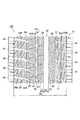
以下において、第2実施形態に係る空気入りタイヤ1Bのトレッドパターンの構成について、図8〜図10を参照しながら説明する。図8は、第2実施形態に係る空気入りタイヤ1Bのトレッドパターンを示す展開図である。図9は、第2実施形態に係る空気入りタイヤ1Bを示す一部拡大図である。図9では、サイプ50が省略されている。図10は、第1実施形態に係る周方向溝32の一部斜視図である。なお、上述した第1の実施の形態に係る空気入りタイヤ1Aと同一部分には同一の符号を付して、相違する部分を主として説明する。
[Second Embodiment]
Below, the structure of the tread pattern of the
図8及び図9に示すように、周方向溝32のトレッドショルダー側に位置する陸部22において、ラグ溝42の一方の端部は、周方向溝31に開口し、ラグ溝42の他方の端部は、陸部22内で終結している。すなわち、陸部22は、リブ状に形成されている。
As shown in FIGS. 8 and 9, in the
周方向溝32のタイヤ赤道面CS側に位置する陸部23において、ラグ溝43は、陸部23を分断している。
In the
図10に示すように、溝内陸部70の平滑溝部60側に位置する内側端71に沿って延びる直線L3は、タイヤ赤道面CSに対して傾いている。すなわち、内側端71は、タイヤ周方向に対してジグザグ状に形成されている。
As shown in FIG. 10, a straight line L3 extending along the
(作用・効果)
第2実施形態では、溝内陸部70の平滑溝部60側に位置する内側端71に沿って延びる直線L3は、タイヤ赤道面CSに対して傾いている。これによれば、周方向溝32に入り込んだ雪に細溝80が引っかかる効果(いわゆる、エッジ効果)が増大するため、氷雪路における駆動性能や制動性能をさらに向上させることができる。
(Action / Effect)
In 2nd Embodiment, the straight line L3 extended along the
[その他の実施の形態]
上述したように、本発明の実施の形態を通じて本発明の内容を開示したが、この開示の一部をなす論述及び図面は、本発明を限定するものであると理解すべきではない。
[Other embodiments]
As described above, the contents of the present invention have been disclosed through the embodiments of the present invention. However, it should not be understood that the descriptions and drawings constituting a part of this disclosure limit the present invention.
実施形態では、平滑溝部60及び溝内陸部70は、複数の周方向溝30のうち、トレッド幅方向に沿った幅が最も広い周方向溝32内に形成されているものとして説明したが、これに限定されるものではなく、他の周方向溝30に形成されていてもよく、複数の周方向溝30内に形成されていても勿論よい。
In the embodiment, the
実施形態では、平滑溝部60は、溝内陸部70よりもタイヤ赤道面CS側に設けられているものとして説明したが、これに限定されるものではなく、例えば、位置が逆、すなわち溝内陸部70よりもトレッドショルダー部側に設けられていても勿論よい。
In the embodiment, the
実施形態では、トレッド幅方向及びタイヤ径方向における溝内陸部70の断面は、略四角形状であるものとして説明したが、これに限定されるものではなく、略三角形状や略台形状であってもよいことは勿論である。
In the embodiment, the cross section of the
実施形態では、空気入りタイヤ1Aは、ビード部やカーカス層、ベルト層(不図示)を備える一般的なラジアルタイヤであるものとして説明したが、これに限定されるものではなく、ラジアルタイヤ以外のタイヤ(例えば、バイアスタイヤ)であってもよく、チューブ付きタイヤであってもよい。 In the embodiment, the pneumatic tire 1 </ b> A has been described as a general radial tire including a bead portion, a carcass layer, and a belt layer (not shown). However, the pneumatic tire 1 </ b> A is not limited to this and is not a radial tire. A tire (for example, a bias tire) may be sufficient and a tire with a tube may be sufficient.
この開示から当業者には様々な代替実施の形態、実施例及び運用技術が明らかとなろう。したがって、本発明の技術的範囲は、上述の説明から妥当な特許請求の範囲に係る発明特定事項によってのみ定められるものである。 From this disclosure, various alternative embodiments, examples and operational techniques will be apparent to those skilled in the art. Therefore, the technical scope of the present invention is defined only by the invention specifying matters according to the scope of claims reasonable from the above description.
(比較評価)
次に、本発明の効果をさらに明確にするために、以下の比較例及び実施例1,2に係る空気入りタイヤを用いて行った比較評価について説明する。なお、本発明はこれらの例によってなんら限定されるものではない。
(Comparison evaluation)
Next, in order to further clarify the effect of the present invention, a comparative evaluation performed using the following comparative examples and pneumatic tires according to Examples 1 and 2 will be described. In addition, this invention is not limited at all by these examples.
各空気入りタイヤに関するデータは、以下に示す条件において測定された。 Data on each pneumatic tire was measured under the following conditions.
・ タイヤサイズ : 205/55R16
・ ホイールサイズ : 6.5J×16
・ 内圧条件 : 正規内圧
これらの各空気入りタイヤのトレッドパターンの構成、雪路での操縦性能、雪路での制動性能、雪路での駆動性能、シャーベットスノー性能、雨路でのハイドロプレーニング性能について、表1を参照しながら説明する。

・ Wheel size: 6.5J × 16
・ Internal pressure condition: Regular internal pressure Configuration of tread pattern of each of these pneumatic tires, driving performance on snowy road, braking performance on snowy road, driving performance on snowy road, sherbet snow performance, hydroplaning performance on rainy road Will be described with reference to Table 1.
ここで、比較例及び実施例1,2に係る空気入りタイヤについて、簡単に説明する。なお、各空気入りタイヤでは、以下で説明する周方向溝32内に形成される平滑溝部60及び溝内陸部70、及び、周方向溝に隣接する陸部22,陸部23の構成以外については、全て同一である。
Here, the pneumatic tire according to the comparative example and Examples 1 and 2 will be briefly described. In each pneumatic tire, except for the configuration of the
比較例に係る空気入りタイヤ100では、周方向溝32内に平滑溝部60及び溝内陸部70が形成されていない。周方向溝32のタイヤ赤道面CS側に位置する陸部23は、リブ状に形成されている(図11参照)。
In the
実施例1に係る空気入りタイヤ1Aでは、第1実施形態で説明したように、周方向溝32内に平滑溝部60及び溝内陸部70(細溝80)が形成されている。溝内陸部70の平滑溝部60側に位置する内側端71に沿って延びる直線L1は、タイヤ赤道面CSと略平行である。周方向溝32のタイヤ赤道面CS側に位置する陸部23は、リブ状に形成されている(図1〜図5参照)。
In the pneumatic tire 1 </ b> A according to Example 1, as described in the first embodiment, the
実施例2に係る空気入りタイヤ1Bでは、第2実施形態で説明したように、周方向溝32内に平滑溝部60及び溝内陸部70(細溝80)が形成されている。溝内陸部70の平滑溝部60側に位置する内側端71に沿って延びる直線L3は、タイヤ赤道面CSに対して傾いている。周方向溝32のトレッドショルダー側に位置する陸部22は、リブ状に形成されている(図8〜図10参照)。
In the pneumatic tire 1 </ b> B according to Example 2, as described in the second embodiment, the
<雪路での操縦性能>
雪路での操縦性能(直進性やコーナーリング性、レーンチェンジ性などの総合性能)は、雪路のコース上において、各空気入りタイヤを装着した車両を走行させることによって評価した。なお、表1は、比較例に係る空気入りタイヤを装着した車両における操縦性能を基準(100)として、その他の空気入りタイヤを装着した車両における操縦性能が指数化された値を示す。指数が大きいほど、雪路での操縦性能が優れている。
<Maneuvering performance on snowy roads>
Steering performance on snowy roads (total performance including straightness, cornering, and lane changeability) was evaluated by running a vehicle equipped with pneumatic tires on the snowy road course. Table 1 shows values obtained by indexing the steering performance in a vehicle equipped with other pneumatic tires, with the steering performance in the vehicle fitted with the pneumatic tire according to the comparative example as a reference (100). The larger the index, the better the maneuvering performance on snowy roads.
この結果、実施例1に係る空気入りタイヤ1A及び実施例2に係る空気入りタイヤ1Bを装着した車両は、比較例に係る空気入りタイヤ100を装着した車両と比較して、雪路での操縦性能に優れていることが分かった。すなわち、周方向溝32に平滑溝部60及び溝内陸部70が形成され、かつ溝内陸部70に細溝80が形成された空気入りタイヤは、雪路での操縦性能を向上させることが分かる。
As a result, the vehicle equipped with the
<雪路での制動性能>
雪路での制動性能は、雪路のコース上において、各空気入りタイヤを装着した車両を速度40km/hで走行させ、走行中の車両が急停止するまでの距離(制動距離)によって評価した。なお、表1は、比較例に係る空気入りタイヤを装着した車両における制動距離を基準(100)として、その他の空気入りタイヤを装着した車両の制動距離が指数化された値を示す。指数が大きいほど、雪路での制動性能が優れている。
<Brake performance on snowy roads>
The braking performance on snowy roads was evaluated based on the distance (braking distance) from when the vehicle equipped with each pneumatic tire traveled at a speed of 40 km / h on the snowy road course until the running vehicle stopped suddenly. . Table 1 shows values obtained by indexing the braking distances of the vehicles equipped with other pneumatic tires, with the braking distance of the vehicle equipped with the pneumatic tires according to the comparative example as a reference (100). The larger the index, the better the braking performance on snowy roads.
この結果、実施例1に係る空気入りタイヤ1A及び実施例2に係る空気入りタイヤ1Bを装着した車両は、比較例に係る空気入りタイヤ100を装着した車両と比較して、雪路での制動性能に優れていることが分かった。すなわち、周方向溝32に平滑溝部60及び溝内陸部70が形成され、かつ溝内陸部70に細溝80が形成された空気入りタイヤは、雪路での制動性能を向上させることが分かる。
As a result, the vehicle equipped with the
<雪路での駆動性能>
雪路での駆動性能は、雪路のコース上において、各空気入りタイヤを装着した車両を、停止状態から50m間走行させて、車両の加速時間によって評価した。なお、表1は、比較例に係る空気入りタイヤを装着した車両における加速時間を基準(100)として、その他の空気入りタイヤを装着した車両における加速時間が指数化された値を示す。指数が大きいほど、雪路での駆動性能が優れている。
<Driving performance on snowy roads>
The driving performance on the snowy road was evaluated based on the acceleration time of the vehicle on which the pneumatic tire was mounted for 50 m from the stopped state on the course of the snowy road. Table 1 shows values obtained by indexing the acceleration time in vehicles equipped with other pneumatic tires, with the acceleration time in the vehicle equipped with pneumatic tires according to the comparative example as a reference (100). The larger the index, the better the driving performance on snowy roads.
この結果、実施例1に係る空気入りタイヤ1A及び実施例2に係る空気入りタイヤ1Bを装着した車両は、比較例に係る空気入りタイヤ100を装着した車両と比較して、雪路での駆動性能に優れていることが分かった。すなわち、周方向溝32に平滑溝部60及び溝内陸部70が形成され、かつ溝内陸部70に細溝80が形成された空気入りタイヤは、雪路での駆動性能を向上させるすることが分かる。
As a result, the vehicle equipped with the
<シャーベットスノー性能>
シャーベットスノー性能は、含水率80〜90%のシャーベット状(スラッシュ状も含む)の雪路のコース上において、気温0±1度の条件下のもと、各空気入りタイヤを装着した車両を加速させ、各車両に装着された空気入りタイヤが路面に接しなくなるまでの限界速度によって評価した。なお、表1は、比較例に係る空気入りタイヤを装着した車両の限界速度を基準(100)として、その他の空気入りタイヤを装着した車両の限界速度が指数化された値を示す。指数が大きいほど、シャーベットスノー性能が優れている。
<Sherbet snow performance>
The sherbet snow performance accelerates vehicles equipped with pneumatic tires on the course of a snowy road with a moisture content of 80-90% (including a slash shape) under a temperature of 0 ± 1 degrees. Then, the evaluation was made based on the limit speed until the pneumatic tire mounted on each vehicle did not contact the road surface. Table 1 shows values obtained by indexing the critical speeds of vehicles equipped with other pneumatic tires with reference to the critical speed of the vehicle equipped with the pneumatic tire according to the comparative example as a reference (100). The larger the index, the better the sherbet snow performance.
この結果、実施例1に係る空気入りタイヤ1A及び実施例2に係る空気入りタイヤ1Bを装着した車両は、比較例に係る空気入りタイヤ100を装着した車両と比較して、シャーベットスノー性能に優れていることが分かった。すなわち、周方向溝32に平滑溝部60及び溝内陸部70が形成され、かつ溝内陸部70に細溝80が形成された空気入りタイヤは、シャーベットスノー性能を向上させることが分かる。
As a result, the vehicle equipped with the
<雨路でのハイドロプレーニング性能>
雨路でのハイドロプレーニング性能は、水深5mmの雨路のコース上において、各空気入りタイヤを装着した車両を走行させ、路面から空気入りタイヤが浮き上がって滑走するハイドロプレーニングが発生する限界速度によって評価した。なお、表1は、比較例に係る空気入りタイヤを装着した車両の限界速度を基準(100)として、その他の空気入りタイヤを装着した車両の限界速度が指数化された値を示す。指数が大きいほど、雨路でのハイドロプレーニング性能が優れている。
<Hydroplaning performance on rainy roads>
Hydroplaning performance on rainy roads is evaluated based on the critical speed at which hydroplaning occurs when a vehicle equipped with pneumatic tires is run on a rainy road course with a depth of 5 mm and the pneumatic tires lift off the road surface. did. Table 1 shows values obtained by indexing the critical speeds of vehicles equipped with other pneumatic tires with reference to the critical speed of the vehicle equipped with the pneumatic tire according to the comparative example as a reference (100). The larger the index, the better the hydroplaning performance on the rainy road.
この結果、実施例1に係る空気入りタイヤ1A及び実施例2に係る空気入りタイヤ1Bを装着した車両は、比較例に係る空気入りタイヤ100を装着した車両と比較して、雨路でのハイドロプレーニング性能に優れていることが分かった。すなわち、周方向溝32に平滑溝部60及び溝内陸部70が形成され、かつ溝内陸部70に細溝80が形成された空気入りタイヤは、雨路でのハイドロプレーニング性能を向上させることが分かる。
As a result, the vehicle equipped with the
1A,1B…空気入りタイヤ、10…トレッド踏面、20(21〜25)…陸部、30(31〜34)…周方向溝、32a…溝底、40(41〜45)…ラグ溝、50(51〜55)…サイプ、60…平滑溝部、70…溝内陸部、71…内側端、72…上面部、80…細溝、81…溝底、85…切欠き部、90…空隙
DESCRIPTION OF
Claims (13)
前記周方向溝内には、
前記周方向溝の溝底の表面が平滑な平滑溝部と、
前記周方向溝の溝底よりも前記トレッド踏面側に隆起する溝内陸部とが形成され、
前記溝内陸部には、トレッド幅方向に沿って延びる複数の細溝が形成され、
前記周方向溝のトレッド幅方向に沿った幅は、前記トレッド踏面のトレッド幅方向に沿った幅に対して5〜30%である空気入りタイヤ。 A pneumatic tire in which a circumferential groove extending along a tire circumferential direction is formed by a land portion constituting a tread surface that is in contact with a road surface,
In the circumferential groove,
A smooth groove portion having a smooth surface at the bottom of the circumferential groove;
A groove inland portion that protrudes toward the tread tread side from the groove bottom of the circumferential groove is formed,
The groove inland portion is formed with a plurality of narrow grooves extending along the tread width direction,
The pneumatic tire has a width along the tread width direction of the circumferential groove of 5 to 30% with respect to a width along the tread width direction of the tread surface.
前記平滑溝部と前記溝内陸部とが形成された前記周方向溝は、複数の前記周方向溝のうち、トレッド幅方向に沿った幅が最も広い請求項1に記載の空気入りタイヤ。 A plurality of the circumferential grooves are provided,
The pneumatic tire according to claim 1, wherein the circumferential groove in which the smooth groove portion and the groove inland portion are formed has the widest width along the tread width direction among the plurality of circumferential grooves.
前記平滑溝部からタイヤ赤道面までのトレッド幅方向に沿った距離は、タイヤ周方向に沿って一定である請求項1に記載の空気入りタイヤ。 While the cross-sectional shape of the smooth groove portion along the tread width direction and the tire radial direction is constant along the tire circumferential direction,
The pneumatic tire according to claim 1, wherein a distance along the tread width direction from the smooth groove portion to the tire equatorial plane is constant along the tire circumferential direction.
前記切欠き部の前記タイヤ周方向に沿った幅は、前記細溝のタイヤ周方向に沿った幅と略同一である請求項1に記載の空気入りタイヤ。 The land portion is formed with a notch extending from the narrow groove in the tread width direction,
The pneumatic tire according to claim 1, wherein a width of the cutout portion along the tire circumferential direction is substantially the same as a width of the narrow groove along the tire circumferential direction.
Priority Applications (7)
| Application Number | Priority Date | Filing Date | Title |
|---|---|---|---|
| JP2008174656A JP5294735B2 (en) | 2008-07-03 | 2008-07-03 | Pneumatic tire |
| RU2011103726/11A RU2466878C2 (en) | 2008-07-03 | 2009-06-24 | Pneumatic tire |
| KR1020107029519A KR20110013538A (en) | 2008-07-03 | 2009-06-24 | Pneumatic tire |
| CN2009801255490A CN102076508B (en) | 2008-07-03 | 2009-06-24 | Pneumatic tire |
| US13/002,167 US9079460B2 (en) | 2008-07-03 | 2009-06-24 | Pneumatic tire |
| PCT/JP2009/061521 WO2010001785A1 (en) | 2008-07-03 | 2009-06-24 | Pneumatic tire |
| EP20090773363 EP2308695B1 (en) | 2008-07-03 | 2009-06-24 | Pneumatic tire |
Applications Claiming Priority (1)
| Application Number | Priority Date | Filing Date | Title |
|---|---|---|---|
| JP2008174656A JP5294735B2 (en) | 2008-07-03 | 2008-07-03 | Pneumatic tire |
Publications (3)
| Publication Number | Publication Date |
|---|---|
| JP2010012931A true JP2010012931A (en) | 2010-01-21 |
| JP2010012931A5 JP2010012931A5 (en) | 2011-11-10 |
| JP5294735B2 JP5294735B2 (en) | 2013-09-18 |
Family
ID=41465883
Family Applications (1)
| Application Number | Title | Priority Date | Filing Date |
|---|---|---|---|
| JP2008174656A Expired - Fee Related JP5294735B2 (en) | 2008-07-03 | 2008-07-03 | Pneumatic tire |
Country Status (7)
| Country | Link |
|---|---|
| US (1) | US9079460B2 (en) |
| EP (1) | EP2308695B1 (en) |
| JP (1) | JP5294735B2 (en) |
| KR (1) | KR20110013538A (en) |
| CN (1) | CN102076508B (en) |
| RU (1) | RU2466878C2 (en) |
| WO (1) | WO2010001785A1 (en) |
Cited By (13)
| Publication number | Priority date | Publication date | Assignee | Title |
|---|---|---|---|---|
| WO2011111352A1 (en) * | 2010-03-08 | 2011-09-15 | 株式会社ブリヂストン | Pneumatic tire |
| JP2011183926A (en) * | 2010-03-08 | 2011-09-22 | Bridgestone Corp | Pneumatic tire |
| JP2011183927A (en) * | 2010-03-08 | 2011-09-22 | Bridgestone Corp | Pneumatic tire |
| JP2011225030A (en) * | 2010-04-15 | 2011-11-10 | Bridgestone Corp | Pneumatic tire |
| JP2012046105A (en) * | 2010-08-27 | 2012-03-08 | Bridgestone Corp | Tire |
| JP2012101745A (en) * | 2010-11-12 | 2012-05-31 | Yokohama Rubber Co Ltd:The | Pneumatic tire and metal mold for vulcanizing thereof |
| WO2013191119A1 (en) * | 2012-06-19 | 2013-12-27 | 株式会社ブリヂストン | Tire |
| JP2014000891A (en) * | 2012-06-19 | 2014-01-09 | Bridgestone Corp | Tire |
| JP2014000892A (en) * | 2012-06-19 | 2014-01-09 | Bridgestone Corp | Tire |
| JP2015044591A (en) * | 2014-12-09 | 2015-03-12 | 株式会社ブリヂストン | Tire |
| WO2017082405A1 (en) * | 2015-11-12 | 2017-05-18 | 株式会社ブリヂストン | Tire |
| WO2017082407A1 (en) * | 2015-11-12 | 2017-05-18 | 株式会社ブリヂストン | Tire |
| JP2019184497A (en) * | 2018-04-13 | 2019-10-24 | 住友ゴム工業株式会社 | Method and device for evaluating performance of tire |
Families Citing this family (16)
| Publication number | Priority date | Publication date | Assignee | Title |
|---|---|---|---|---|
| JP5498245B2 (en) * | 2010-05-10 | 2014-05-21 | 株式会社ブリヂストン | tire |
| EP2614967B1 (en) * | 2010-09-09 | 2017-11-08 | Bridgestone Corporation | Tire |
| FR2983114B1 (en) * | 2011-11-25 | 2013-12-20 | Michelin Soc Tech | MOLD COMPRISING A CAVITY FOR MOLDING A CLOSURE DEVICE IN A GROOVE |
| FR2984232B1 (en) * | 2011-12-20 | 2014-02-07 | Michelin Soc Tech | SUMMIT FOR TIRE AIRCRAFT |
| JP5600143B2 (en) * | 2012-07-04 | 2014-10-01 | 株式会社ブリヂストン | tire |
| JP6012397B2 (en) * | 2012-10-24 | 2016-10-25 | 株式会社ブリヂストン | Pneumatic tire |
| JP5806707B2 (en) * | 2013-07-03 | 2015-11-10 | 住友ゴム工業株式会社 | Pneumatic tire |
| JP6364342B2 (en) | 2014-12-22 | 2018-07-25 | 東洋ゴム工業株式会社 | Pneumatic tire |
| USD787424S1 (en) * | 2015-03-17 | 2017-05-23 | The Goodyear Tire & Rubber Company | Tire |
| CN105346334A (en) * | 2015-11-10 | 2016-02-24 | 青岛双星轮胎工业有限公司 | Industrial radial tire |
| FR3044597A1 (en) * | 2015-12-07 | 2017-06-09 | Michelin & Cie | PNEUMATIC TIRE TREAD FOR HEAVY VEHICLE TYPE GENIE CIVIL |
| US20190092101A1 (en) * | 2017-09-22 | 2019-03-28 | The Goodyear Tire & Rubber Company | Tread for a tire |
| JP6930944B2 (en) * | 2018-06-21 | 2021-09-01 | 株式会社ブリヂストン | tire |
| JP7147354B2 (en) * | 2018-08-10 | 2022-10-05 | 横浜ゴム株式会社 | pneumatic tire |
| WO2023129169A1 (en) * | 2021-12-31 | 2023-07-06 | Compagnie Generale Des Etablissements Michelin | Heavy truck tire tread with rib element to manage irregular wear |
| JP2023124168A (en) * | 2022-02-25 | 2023-09-06 | 住友ゴム工業株式会社 | tire |
Citations (7)
| Publication number | Priority date | Publication date | Assignee | Title |
|---|---|---|---|---|
| JPS61166708A (en) * | 1985-01-19 | 1986-07-28 | Toyo Tire & Rubber Co Ltd | Pneumatic tire |
| JPS63297108A (en) * | 1987-05-28 | 1988-12-05 | Sumitomo Rubber Ind Ltd | Pneumatic tire for heavy load vehicle |
| JPH01215604A (en) * | 1988-02-23 | 1989-08-29 | Toyo Tire & Rubber Co Ltd | Pneumatic radial tire with cipher on its groove bottom for heavy load |
| JPH01215603A (en) * | 1988-02-23 | 1989-08-29 | Toyo Tire & Rubber Co Ltd | Pneumatic tire tread pattern |
| JPH10226207A (en) * | 1997-02-17 | 1998-08-25 | Bridgestone Corp | Pneumatic tire |
| JP2000177331A (en) * | 1998-12-15 | 2000-06-27 | Bridgestone Corp | Pneumatic tire |
| JP2001277818A (en) * | 2000-01-28 | 2001-10-10 | Bridgestone Corp | Pneumatic tire |
Family Cites Families (21)
| Publication number | Priority date | Publication date | Assignee | Title |
|---|---|---|---|---|
| NL130257C (en) * | 1963-07-23 | Michelin & Cie | ||
| GB1214629A (en) * | 1967-03-17 | 1970-12-02 | Dunlop Co Ltd | Improved tyre construction |
| US5492161A (en) * | 1985-01-19 | 1996-02-20 | Toyo Tire & Rubber Company, Limited | Pneumatic tire with groove steps having sipes |
| US5154216A (en) * | 1990-01-05 | 1992-10-13 | Sumitomo Rubber Industries, Ltd. | Radial tire for heavy duty vehicles |
| US5685927A (en) * | 1992-09-30 | 1997-11-11 | The Goodyear Tire & Rubber Company | Run-flat tire with wet handling design |
| JP2643065B2 (en) * | 1992-10-19 | 1997-08-20 | 住友ゴム工業株式会社 | Pneumatic tire |
| JP3901743B2 (en) * | 1993-12-22 | 2007-04-04 | 住友ゴム工業株式会社 | Pneumatic tire |
| JP2644970B2 (en) * | 1993-12-27 | 1997-08-25 | 住友ゴム工業株式会社 | Pneumatic tire |
| JP2799137B2 (en) * | 1993-12-29 | 1998-09-17 | 住友ゴム工業株式会社 | Pneumatic tire |
| DE69613952T2 (en) * | 1995-12-29 | 2001-11-08 | Sumitomo Rubber Industries Ltd., Kobe | tire |
| US6439284B1 (en) * | 1997-10-03 | 2002-08-27 | The Goodyear Tire & Rubber Company | Tread for a pneumatic tire including aquachannel |
| US6123130A (en) * | 1997-11-11 | 2000-09-26 | Bridgestone/Firestone, Inc. | Tire having improved wet stopping capability |
| US6340041B1 (en) * | 1998-12-11 | 2002-01-22 | Sumitomo Rubber Industries | Pneumatic tire including two wide circumferential grooves |
| JP4404398B2 (en) | 1999-03-11 | 2010-01-27 | 株式会社ブリヂストン | Pneumatic tire |
| JP3493177B2 (en) * | 2000-12-19 | 2004-02-03 | 住友ゴム工業株式会社 | Pneumatic tire |
| CN101454168B (en) * | 2006-03-31 | 2011-03-02 | 株式会社普利司通 | Pneumatic tire |
| JP5148102B2 (en) * | 2006-11-24 | 2013-02-20 | 東洋ゴム工業株式会社 | Pneumatic tire |
| JP2008174656A (en) | 2007-01-19 | 2008-07-31 | Oshika:Kk | Highly water-resistant adhesive composition |
| JP4488055B2 (en) * | 2007-11-02 | 2010-06-23 | 横浜ゴム株式会社 | Pneumatic tire |
| JP5160870B2 (en) * | 2007-12-10 | 2013-03-13 | 東洋ゴム工業株式会社 | Pneumatic tire |
| DE102008037497A1 (en) | 2008-10-30 | 2010-05-06 | Continental Reifen Deutschland Gmbh | Vehicle tires |
-
2008
- 2008-07-03 JP JP2008174656A patent/JP5294735B2/en not_active Expired - Fee Related
-
2009
- 2009-06-24 WO PCT/JP2009/061521 patent/WO2010001785A1/en active Application Filing
- 2009-06-24 EP EP20090773363 patent/EP2308695B1/en not_active Not-in-force
- 2009-06-24 KR KR1020107029519A patent/KR20110013538A/en not_active Application Discontinuation
- 2009-06-24 US US13/002,167 patent/US9079460B2/en not_active Expired - Fee Related
- 2009-06-24 CN CN2009801255490A patent/CN102076508B/en not_active Expired - Fee Related
- 2009-06-24 RU RU2011103726/11A patent/RU2466878C2/en active
Patent Citations (7)
| Publication number | Priority date | Publication date | Assignee | Title |
|---|---|---|---|---|
| JPS61166708A (en) * | 1985-01-19 | 1986-07-28 | Toyo Tire & Rubber Co Ltd | Pneumatic tire |
| JPS63297108A (en) * | 1987-05-28 | 1988-12-05 | Sumitomo Rubber Ind Ltd | Pneumatic tire for heavy load vehicle |
| JPH01215604A (en) * | 1988-02-23 | 1989-08-29 | Toyo Tire & Rubber Co Ltd | Pneumatic radial tire with cipher on its groove bottom for heavy load |
| JPH01215603A (en) * | 1988-02-23 | 1989-08-29 | Toyo Tire & Rubber Co Ltd | Pneumatic tire tread pattern |
| JPH10226207A (en) * | 1997-02-17 | 1998-08-25 | Bridgestone Corp | Pneumatic tire |
| JP2000177331A (en) * | 1998-12-15 | 2000-06-27 | Bridgestone Corp | Pneumatic tire |
| JP2001277818A (en) * | 2000-01-28 | 2001-10-10 | Bridgestone Corp | Pneumatic tire |
Cited By (22)
| Publication number | Priority date | Publication date | Assignee | Title |
|---|---|---|---|---|
| US9352619B2 (en) | 2010-03-08 | 2016-05-31 | Bridgestone Corporation | Pneumatic tire |
| JP2011183926A (en) * | 2010-03-08 | 2011-09-22 | Bridgestone Corp | Pneumatic tire |
| JP2011183927A (en) * | 2010-03-08 | 2011-09-22 | Bridgestone Corp | Pneumatic tire |
| WO2011111352A1 (en) * | 2010-03-08 | 2011-09-15 | 株式会社ブリヂストン | Pneumatic tire |
| JP2011225030A (en) * | 2010-04-15 | 2011-11-10 | Bridgestone Corp | Pneumatic tire |
| JP2012046105A (en) * | 2010-08-27 | 2012-03-08 | Bridgestone Corp | Tire |
| JP2012101745A (en) * | 2010-11-12 | 2012-05-31 | Yokohama Rubber Co Ltd:The | Pneumatic tire and metal mold for vulcanizing thereof |
| US9809062B2 (en) | 2012-06-19 | 2017-11-07 | Bridgestone Corporation | Tire |
| JP2014000892A (en) * | 2012-06-19 | 2014-01-09 | Bridgestone Corp | Tire |
| WO2013191119A1 (en) * | 2012-06-19 | 2013-12-27 | 株式会社ブリヂストン | Tire |
| JP2014000891A (en) * | 2012-06-19 | 2014-01-09 | Bridgestone Corp | Tire |
| JP2015044591A (en) * | 2014-12-09 | 2015-03-12 | 株式会社ブリヂストン | Tire |
| JPWO2017082405A1 (en) * | 2015-11-12 | 2018-08-30 | 株式会社ブリヂストン | tire |
| WO2017082407A1 (en) * | 2015-11-12 | 2017-05-18 | 株式会社ブリヂストン | Tire |
| JPWO2017082407A1 (en) * | 2015-11-12 | 2018-08-30 | 株式会社ブリヂストン | tire |
| WO2017082405A1 (en) * | 2015-11-12 | 2017-05-18 | 株式会社ブリヂストン | Tire |
| RU2702944C1 (en) * | 2015-11-12 | 2019-10-14 | Бриджстоун Корпорейшн | Tire |
| JP2020040665A (en) * | 2015-11-12 | 2020-03-19 | 株式会社ブリヂストン | tire |
| JP2020045100A (en) * | 2015-11-12 | 2020-03-26 | 株式会社ブリヂストン | tire |
| JP2020045099A (en) * | 2015-11-12 | 2020-03-26 | 株式会社ブリヂストン | tire |
| JP2019184497A (en) * | 2018-04-13 | 2019-10-24 | 住友ゴム工業株式会社 | Method and device for evaluating performance of tire |
| JP7056344B2 (en) | 2018-04-13 | 2022-04-19 | 住友ゴム工業株式会社 | Tire performance evaluation method and performance evaluation device |
Also Published As
| Publication number | Publication date |
|---|---|
| JP5294735B2 (en) | 2013-09-18 |
| RU2011103726A (en) | 2012-08-10 |
| US20110146863A1 (en) | 2011-06-23 |
| WO2010001785A1 (en) | 2010-01-07 |
| EP2308695B1 (en) | 2012-11-21 |
| CN102076508A (en) | 2011-05-25 |
| RU2466878C2 (en) | 2012-11-20 |
| EP2308695A4 (en) | 2011-08-31 |
| US9079460B2 (en) | 2015-07-14 |
| KR20110013538A (en) | 2011-02-09 |
| EP2308695A1 (en) | 2011-04-13 |
| CN102076508B (en) | 2013-12-18 |
Similar Documents
| Publication | Publication Date | Title |
|---|---|---|
| JP5294735B2 (en) | Pneumatic tire | |
| CN108146154B (en) | Tyre for vehicle wheels | |
| JP5140115B2 (en) | Pneumatic tire | |
| JP4581732B2 (en) | Pneumatic tire | |
| RU2471640C2 (en) | Pneumatic tire | |
| JP4769858B2 (en) | Pneumatic tire | |
| JP5102711B2 (en) | Pneumatic tire | |
| US9555669B2 (en) | Pneumatic tire | |
| CN108688411B (en) | Pneumatic tire | |
| JP6819133B2 (en) | tire | |
| JP6558297B2 (en) | Pneumatic tire | |
| CN107639975B (en) | Tyre for vehicle wheels | |
| KR102569782B1 (en) | Tire | |
| JP7106982B2 (en) | tire | |
| JP6097261B2 (en) | Pneumatic tire | |
| KR101017152B1 (en) | Pneumatic tire | |
| JP4928785B2 (en) | Pneumatic tire | |
| CN110091676B (en) | Tyre for vehicle wheels | |
| JP4721892B2 (en) | Pneumatic tire | |
| CN113580850A (en) | Tyre for vehicle wheels | |
| JP2008062841A (en) | Pneumatic tire | |
| JP5357662B2 (en) | tire | |
| JP4473689B2 (en) | Pneumatic tire | |
| JP5343429B2 (en) | Pneumatic tire | |
| JP2009018605A (en) | Pneumatic tire |
Legal Events
| Date | Code | Title | Description |
|---|---|---|---|
| A621 | Written request for application examination |
Free format text: JAPANESE INTERMEDIATE CODE: A621 Effective date: 20110701 |
|
| A521 | Written amendment |
Free format text: JAPANESE INTERMEDIATE CODE: A523 Effective date: 20110926 |
|
| A131 | Notification of reasons for refusal |
Free format text: JAPANESE INTERMEDIATE CODE: A131 Effective date: 20121030 |
|
| A521 | Written amendment |
Free format text: JAPANESE INTERMEDIATE CODE: A523 Effective date: 20121227 |
|
| TRDD | Decision of grant or rejection written | ||
| A01 | Written decision to grant a patent or to grant a registration (utility model) |
Free format text: JAPANESE INTERMEDIATE CODE: A01 Effective date: 20130604 |
|
| A61 | First payment of annual fees (during grant procedure) |
Free format text: JAPANESE INTERMEDIATE CODE: A61 Effective date: 20130611 |
|
| R150 | Certificate of patent or registration of utility model |
Ref document number: 5294735 Country of ref document: JP Free format text: JAPANESE INTERMEDIATE CODE: R150 Free format text: JAPANESE INTERMEDIATE CODE: R150 |
|
| R250 | Receipt of annual fees |
Free format text: JAPANESE INTERMEDIATE CODE: R250 |
|
| R250 | Receipt of annual fees |
Free format text: JAPANESE INTERMEDIATE CODE: R250 |
|
| R250 | Receipt of annual fees |
Free format text: JAPANESE INTERMEDIATE CODE: R250 |
|
| R250 | Receipt of annual fees |
Free format text: JAPANESE INTERMEDIATE CODE: R250 |
|
| R250 | Receipt of annual fees |
Free format text: JAPANESE INTERMEDIATE CODE: R250 |
|
| LAPS | Cancellation because of no payment of annual fees |