JP2010012733A - Suction device and liquid droplet ejecting apparatus equipped therewith - Google Patents
Suction device and liquid droplet ejecting apparatus equipped therewith Download PDFInfo
- Publication number
- JP2010012733A JP2010012733A JP2008176517A JP2008176517A JP2010012733A JP 2010012733 A JP2010012733 A JP 2010012733A JP 2008176517 A JP2008176517 A JP 2008176517A JP 2008176517 A JP2008176517 A JP 2008176517A JP 2010012733 A JP2010012733 A JP 2010012733A
- Authority
- JP
- Japan
- Prior art keywords
- suction
- functional liquid
- cap
- units
- pressure
- Prior art date
- Legal status (The legal status is an assumption and is not a legal conclusion. Google has not performed a legal analysis and makes no representation as to the accuracy of the status listed.)
- Granted
Links
- 239000007788 liquid Substances 0.000 title claims abstract description 250
- 230000007246 mechanism Effects 0.000 claims abstract description 35
- 238000011144 upstream manufacturing Methods 0.000 claims abstract description 13
- 239000002699 waste material Substances 0.000 claims description 85
- 238000009826 distribution Methods 0.000 claims description 38
- 238000011010 flushing procedure Methods 0.000 claims description 36
- 238000000926 separation method Methods 0.000 claims description 5
- 238000007599 discharging Methods 0.000 claims 1
- 238000012545 processing Methods 0.000 abstract description 27
- 238000000034 method Methods 0.000 description 25
- 230000008569 process Effects 0.000 description 17
- 238000012423 maintenance Methods 0.000 description 10
- 230000001276 controlling effect Effects 0.000 description 9
- 238000001514 detection method Methods 0.000 description 6
- 239000010808 liquid waste Substances 0.000 description 4
- 239000003086 colorant Substances 0.000 description 3
- 238000004891 communication Methods 0.000 description 3
- 238000007689 inspection Methods 0.000 description 3
- 238000003860 storage Methods 0.000 description 3
- 239000000758 substrate Substances 0.000 description 3
- KNMAVSAGTYIFJF-UHFFFAOYSA-N 1-[2-[(2-hydroxy-3-phenoxypropyl)amino]ethylamino]-3-phenoxypropan-2-ol;dihydrochloride Chemical compound Cl.Cl.C=1C=CC=CC=1OCC(O)CNCCNCC(O)COC1=CC=CC=C1 KNMAVSAGTYIFJF-UHFFFAOYSA-N 0.000 description 2
- 238000010586 diagram Methods 0.000 description 2
- 230000003028 elevating effect Effects 0.000 description 2
- 239000011295 pitch Substances 0.000 description 2
- 238000011084 recovery Methods 0.000 description 2
- 230000008859 change Effects 0.000 description 1
- 230000006835 compression Effects 0.000 description 1
- 238000007906 compression Methods 0.000 description 1
- 238000012937 correction Methods 0.000 description 1
- 238000001035 drying Methods 0.000 description 1
- 238000002474 experimental method Methods 0.000 description 1
- 239000012530 fluid Substances 0.000 description 1
- 230000006872 improvement Effects 0.000 description 1
- 238000004519 manufacturing process Methods 0.000 description 1
- 239000008239 natural water Substances 0.000 description 1
- 230000001105 regulatory effect Effects 0.000 description 1
- 239000011347 resin Substances 0.000 description 1
- 229920005989 resin Polymers 0.000 description 1
- 230000006641 stabilisation Effects 0.000 description 1
- 238000011105 stabilization Methods 0.000 description 1
- 239000004575 stone Substances 0.000 description 1
- 239000000126 substance Substances 0.000 description 1
- 239000000725 suspension Substances 0.000 description 1
Images


Abstract
Description
本発明は、機能液別の複数のインクジェット方式の機能液滴吐出ヘッドのノズル面に対し、離接して機能液を吸引する吸引装置およびこれを備えた液滴吐出装置に関する。 The present invention relates to a suction device for sucking a functional liquid while being in contact with a nozzle surface of a plurality of functional liquid droplet ejection heads of an ink jet method for each functional liquid, and a liquid droplet ejection apparatus including the same.
従来、12個の機能液滴吐出ヘッドを搭載した7台のキャリッジユニットに対応して、12個のキャップを搭載した7台の吸引ユニットを備えた吸引装置が知られている(特許文献1参照)。各吸引装置は、12個のキャップをキャッププレートに搭載したキャップユニットと、キャッププレートを介して12個のキャップを12個の機能液滴吐出ヘッドに対し離接させる離接機構と、12個のキャップに連なる廃液タンクと、二次側を廃液タンクに接続して廃液タンクに吸引圧力を作用させるエジェクタと、12個のキャップと廃液タンクを接続する吸引チューブと、を備えている。
この吸引装置では、各キャップを各機能液滴吐出ヘッドに密接させておいて、一次側に圧縮エアーを導入するようにしてエジェクタを駆動すると、廃液タンクのタンク内および吸引流路が負圧になり、12個のキャップを介して12個の機能液滴吐出ヘッドから機能液の吸引が行われる。また、各キャップを各機能液滴吐出ヘッドから僅かに離間させておいて、各機能液滴吐出ヘッドの捨て吐出(フラッシング)を行わせながらエジェクタを駆動することで、捨て吐出を受け得るようになっている。このように、2つの機能により、12個の機能液滴吐出ヘッドの機能維持および機能回復が行われる。
In this suction device, each cap is in close contact with each functional liquid droplet ejection head, and when the ejector is driven so as to introduce compressed air to the primary side, the inside of the waste liquid tank and the suction flow path become negative pressure. Thus, the functional liquid is sucked from the 12 functional liquid droplet ejection heads via the 12 caps. In addition, each cap is slightly separated from each functional droplet discharge head, and the ejector is driven while discarding (flushing) each functional droplet discharge head, so that it can receive the discard discharge. It has become. Thus, the function maintenance and function recovery of the twelve function liquid droplet ejection heads are performed by two functions.
このような従来の吸引装置では、7台の吸引ユニットがそれぞれ独立しているため、単一の廃液タンクおよび単一のエジェクタが、独立して設けられている。このため、スペース効率が悪化すると共に構造が複雑になる問題があった。
この場合、7台の吸引装置の廃液タンクおよびエジェクタを単一のものに統合すれば、かかる問題は解消される。しかし、多数の吐出ノズルから機能液を吸引する吸引圧力と、キャップに吐出された機能液を吸引する吸引圧力とでは、前者が高く後者が低いため、上記の構成では、吸引を行う吸引装置と捨て吐出を受ける吸引装置とが混在する運転方法をとる場合、両作業を同時に実施することが不可能になってしまう。また、吸引圧力を高低切り替えるにしても、設定圧力が安定するまで時間がかかるため、効率良く吸引を行うことができない。
In such a conventional suction device, since the seven suction units are independent from each other, a single waste liquid tank and a single ejector are provided independently. For this reason, there is a problem that the space efficiency is deteriorated and the structure is complicated.
In this case, the problem can be solved by integrating the waste liquid tanks and ejectors of the seven suction devices into a single unit. However, the suction pressure for sucking the functional liquid from a large number of discharge nozzles and the suction pressure for sucking the functional liquid discharged to the cap are higher in the former and lower in the latter. When an operation method in which a suction device that receives discarded discharge is mixed is used, it is impossible to perform both operations at the same time. Further, even if the suction pressure is switched between high and low, it takes time until the set pressure is stabilized, and therefore suction cannot be performed efficiently.
本発明は、キャップユニット単位で、異なる吸引圧力による吸引処理を自在に行うことができると共に、スペース効率の向上および構造の単純化を図ることができる吸引装置およびこれを備えた液滴吐出装置を提供することを課題としている。 The present invention provides a suction device that can freely perform suction processing with different suction pressures in units of cap units, and that can improve space efficiency and simplify the structure, and a droplet discharge device including the suction device. The issue is to provide.
本発明の吸引装置は、機能液別の複数種のインクジェット方式の機能液滴吐出ヘッドのノズル面に対し、離接して機能液を吸引する吸引装置であって、機能液別の複数種の機能液滴吐出ヘッドに対応する機能液別の複数種のキャップを搭載したキャップユニットと、各キャップを、キャップユニット単位で離接動作させる離接機構と、キャップユニット単位で各キャップから機能液を吸引すると共に、各々吸引圧力が異なる複数台の吸引手段と、上流側を各キャップに接続された複数の個別吸引流路と、下流側を各吸引手段に接続された複数の主吸引流路と、複数の個別吸引流路と複数の主吸引流路との間に介設され、複数の個別吸引流路を合流させると共に、合流後の流路を複数の主吸引流路に対し選択的に連通させる合流流路系と、を備えたことを特徴とする。 The suction device of the present invention is a suction device that sucks and draws a functional liquid by coming into contact with a nozzle surface of a plurality of types of ink jet type functional droplet discharge heads for each functional liquid, and a plurality of types of functions for each functional liquid Cap unit equipped with multiple types of caps for each functional liquid corresponding to the droplet discharge head, a separation / contact mechanism that allows each cap to separate / contact each cap unit, and suction of the functional liquid from each cap for each cap unit And a plurality of suction means each having a different suction pressure, a plurality of individual suction channels connected to each cap on the upstream side, a plurality of main suction channels connected to each suction means on the downstream side, It is interposed between a plurality of individual suction channels and a plurality of main suction channels, and combines the plurality of individual suction channels and selectively communicates the merged channels with the plurality of main suction channels. A merging channel system Characterized in that was.
この構成によれば、合流流路系により、機能液の種類別に個別吸引流路を合流できると共に、合流後の個別吸引流路を複数の主吸引流路に対し選択的に連通させることで、任意の1の吸引手段に選択的に連通させることができる。すなわち、吸引手段と同数の主吸引流路が設けられ、任意の主吸引流路を選択することで、高圧または低圧の吸引手段を選択することができるため、所望の吸引圧力による吸引処理を自在に実施することができる。また、個別吸引流路を合流して、各吸引手段に繋がる主吸引流路と連通させることができるため、個別吸引流路ごとに吸引手段を設ける場合に比して、その数を少なくすることができ、スペース効率の向上および構造の単純化を図ることができる。 According to this configuration, the merging channel system allows the individual suction channels to be merged according to the type of the functional liquid, and the individual suction channels after merging are selectively communicated with the plurality of main suction channels. It can be selectively communicated with any one suction means. That is, the same number of main suction flow paths as the suction means are provided, and by selecting an arbitrary main suction flow path, a high-pressure or low-pressure suction means can be selected. Can be implemented. In addition, since the individual suction channels can be joined and communicated with the main suction channel connected to each suction unit, the number of suction units can be reduced as compared with the case where a suction unit is provided for each individual suction channel. Thus, space efficiency can be improved and the structure can be simplified.
また、他の吸引装置は、機能液別のm種(mは複数)のインクジェット方式の機能液滴吐出ヘッドをキャリッジに搭載したヘッドユニットのn台(nは複数)に対応して設けられ、各機能液滴吐出ヘッドのノズル面に離接して機能液を吸引する吸引装置であって、機能液別のm種の機能液滴吐出ヘッドに対応する機能液別のm種のキャップをキャッププレートに組み込んだ、n台のヘッドユニットに対応するn台のキャップユニットと、キャッププレートを介して各キャップを、キャップユニット単位で離接動作させる離接機構と、キャップユニット単位で各キャップから機能液を吸引すると共に、各々吸引圧力が異なるp台(pは複数)の吸引手段と、上流側を各キャップに接続されたm×n本の個別吸引流路と、下流側を各吸引手段に接続されたp本の主吸引流路と、m×n本の個別吸引流路とp本の主吸引流路との間に介設され、m×n本の個別吸引流路を合流させると共に、合流後の流路をp本の主吸引流路に対し選択的に連通させる合流流路系と、を備えたことを特徴とする。 The other suction devices are provided corresponding to n units (n is a plurality) of head units in which m types (m is a plurality) of ink jet type functional liquid droplet ejection heads mounted on a carriage. A suction device for sucking a functional liquid by coming into contact with the nozzle surface of each functional liquid droplet ejection head, and cap plates for m functional liquids corresponding to m functional liquid droplet ejection heads for each functional liquid N cap units corresponding to the n head units, a separation / contact mechanism for separating each cap through the cap plate, and a functional liquid from each cap in the cap unit. P units (p is a plurality) having different suction pressures, mxn individual suction channels connected to the caps on the upstream side, and the suction units on the downstream side. The p main suction channels, the m × n individual suction channels, and the p main suction channels are interposed between the m × n individual suction channels, And a merged channel system for selectively communicating the merged channels with the p main suction channels.
この構成によれば、m×n本の個別吸引流路を、合流流路系により、p本の主吸引流路に合流させることができる。また、p本の主吸引流路を選択することで、任意の1の吸引手段に選択的に連通させることができる。これにより、複数の機能液滴吐出ヘッドに対し、複数のキャップユニットを介して、同時並行的に異なる吸引圧力による吸引処理を実施でき、機能液滴吐出ヘッドの機能維持および機能回復を適切に行うことができる。また、キャップユニットごとに吸引手段を設ける場合に比して、その数を少なくすることができ、スペース効率の向上および構造の単純化を図ることができる。
さらに、例えば、機能液滴吐出ヘッド数(キャップ数)の増加に伴い個別吸引流路の本数が増加した場合であっても、合流流路系により個別吸引流路を合流できるため、主吸引流路および吸引手段の数を増加させる必要がない。さらに、ヘッドユニット数の増加に伴いキャップユニットが増加した場合であっても、増加したp本の主吸引流路は、元からあるp台の吸引手段に各々接続すればよいため、吸引手段の数を増加させる必要がない。
According to this configuration, m × n individual suction channels can be merged with p main suction channels by the merge channel system. Further, by selecting p main suction channels, it is possible to selectively communicate with any one suction means. As a result, a plurality of functional liquid droplet ejection heads can be simultaneously subjected to suction processing using different suction pressures via a plurality of cap units, and the function of the functional liquid droplet ejection head can be appropriately maintained and recovered. be able to. Further, the number of suction means can be reduced for each cap unit, and space efficiency can be improved and the structure can be simplified.
Further, for example, even if the number of individual suction channels increases with the increase in the number of functional liquid droplet ejection heads (number of caps), the individual suction channels can be merged by the merge channel system. There is no need to increase the number of channels and suction means. Furthermore, even if the cap units increase with the increase in the number of head units, the increased p main suction flow paths only need to be connected to the original p suction means. There is no need to increase the number.
この場合、合流流路系は、m×n本の個別吸引流路を、キャップユニット単位で合流させるn台の一次マニホールドと、各主吸引流路の上流側が接続されたp台の二次マニホールドと、n台の一次マニホールドとp台の二次マニホールドとを個々に接続するn×p本の分配吸引流路と、各分配吸引流路に介設したn×p個の分配流路開閉バルブと、を有していることが好ましい。 In this case, the merging channel system includes n primary manifolds for merging mxn individual suction channels in cap units, and p secondary manifolds connected to the upstream side of each main suction channel. And n × p distribution suction passages for individually connecting n primary manifolds and p secondary manifolds, and n × p distribution flow passage opening / closing valves provided in each distribution suction passage It is preferable to have.
この構成によれば、m×n本の個別吸引流路は、一次マニホールドにより、キャップユニットごとにまとめられている。また、吸引手段の台数、二次マニホールドの台数およびキャップユニット1台当りの分配吸引流路の本数(分配流路開閉バルブの個数)は同一数であり、一次マニホールドよりも下流側では、吸引手段の圧力水準ごとにまとめられている。これにより、例えば、機能液滴吐出ヘッド数(キャップ数)の増加に伴い個別吸引流路の本数が増加した場合であっても、一次マニホールドで合流すると共に、増加した一次マニホールドは、圧力水準ごとに、分配吸引流路を介して二次マニホールドで合流することができる。このため、吸引装置の構造を単純化でき、トラブル発生の防止およびメンテナンス性の向上を実現できる。また、m×n本の個別吸引流路の圧力損失を均一化することができる。 According to this configuration, the m × n individual suction channels are grouped for each cap unit by the primary manifold. Further, the number of suction means, the number of secondary manifolds, and the number of distribution suction channels per cap unit (number of distribution channel opening / closing valves) are the same, and suction means are provided downstream of the primary manifold. Are summarized for each pressure level. As a result, for example, even when the number of individual suction flow paths increases with an increase in the number of functional liquid droplet ejection heads (cap number), the primary manifold merges and the increased primary manifold is The secondary manifold can be joined via the distribution suction channel. For this reason, the structure of the suction device can be simplified, and troubles can be prevented and maintenance can be improved. In addition, the pressure loss of the m × n individual suction channels can be made uniform.
また、各個別吸引流路に介設したm×n個の個別流路開閉バルブを、更に備えていることが好ましい。 Moreover, it is preferable to further include m × n individual flow path opening / closing valves interposed in the individual suction flow paths.
この構成によれば、個別流路開閉バルブによって、個々の機能液滴吐出ヘッドに対して、個別吸引流路の開閉を行うことができる。これにより、複数の機能液滴吐出ヘッドにおいて、吸引処理を行うものと行わないものがある場合、各個別流路開閉バルブの開閉により、これを実施することができる。 According to this configuration, the individual suction channel can be opened / closed with respect to each functional liquid droplet ejection head by the individual channel opening / closing valve. Accordingly, when there are a plurality of functional liquid droplet ejection heads that perform and do not perform suction processing, this can be implemented by opening and closing each individual flow path opening and closing valve.
他にも、m種の各機能液滴吐出ヘッドは、同種の複数のもので構成され、これに対応するm種の各キャップは、同種の複数のもので構成され、各個別吸引流路には、上流側に介設された分岐継手により分岐した同種流路を介して、同種の複数のキャップが接続されていることが好ましい。 In addition, each of the m types of functional liquid droplet ejection heads is configured by a plurality of the same types, and each of the m types of caps corresponding thereto is configured by a plurality of the same types. It is preferable that a plurality of caps of the same kind are connected via a homogeneous flow path branched by a branch joint provided upstream.
この構成によれば、複数種の機能液滴吐出ヘッドに対する各キャップに接続された同種流路は、分岐継手により機能液の種類別に1本の個別吸引流路に合流することができる。すなわち、機能液1種類につき、1つの個別流路開閉バルブを介設し、その1つの個別流路開閉バルブの開閉で、複数の同種流路の開閉を行うことができる。これにより、各キャップに個別流路開閉バルブを設ける場合に比して、その数を少なくすることができ、構造を単純化できる。また、複数の機能液滴吐出ヘッドにおいて、機能液別に吸引処理を行うものと行わないものがある場合、各個別流路開閉バルブの開閉により、これを実施することができる。 According to this structure, the same kind flow path connected to each cap with respect to a plurality of types of functional liquid droplet ejection heads can be merged into one individual suction flow path for each type of functional liquid by the branch joint. That is, one individual flow path opening / closing valve is provided for each type of functional liquid, and a plurality of similar flow paths can be opened / closed by opening / closing the single individual flow path opening / closing valve. Thereby, the number can be reduced and the structure can be simplified as compared with the case where the individual channel opening / closing valves are provided in each cap. In addition, when there are a plurality of functional liquid droplet ejection heads that perform a suction process for each functional liquid and those that do not, this can be performed by opening and closing each individual flow path opening / closing valve.
この場合、各吸引手段は、主吸引流路の下流側が接続された廃液タンクと、一次側に圧縮エアーを導入すると共に、二次側を各廃液タンクの上部空間に接続したエジェクタと、を有していることが好ましい。 In this case, each suction means has a waste liquid tank connected to the downstream side of the main suction flow path, and an ejector that introduces compressed air to the primary side and connects the secondary side to the upper space of each waste liquid tank. It is preferable.
この構成によれば、吸引手段の構造を単純化することができると共に、機能液に対する耐薬品性に優れた構造とすることができる。 According to this configuration, the structure of the suction unit can be simplified, and a structure excellent in chemical resistance against the functional liquid can be obtained.
また、各吸引手段は、一次側に圧縮エアーの圧力を調整する圧力調整手段と、圧力調整手段を制御する制御手段と、を更に有していることが好ましい。 Each suction means preferably further includes pressure adjusting means for adjusting the pressure of the compressed air on the primary side and control means for controlling the pressure adjusting means.
この構成によれば、各廃液タンクに導入する吸引のための負圧(吸引圧力)を、機能液の粘性や吸引処理の形態に合わせて簡単に調整することができる。もちろん、異種の機能液を新たに導入する場合や吸引形態を変更する場合等にも、簡単に対応させることができる。なお、圧力調整手段として、レギュレータ(電空レギュレータ)を用いることが、好ましい。 According to this configuration, the negative pressure (suction pressure) for suction introduced into each waste liquid tank can be easily adjusted according to the viscosity of the functional liquid and the form of suction processing. Of course, it is possible to easily cope with a case where a different kind of functional liquid is newly introduced or a suction mode is changed. In addition, it is preferable to use a regulator (electro-pneumatic regulator) as the pressure adjusting means.
この場合、各制御手段は、各キャップユニットにおける吸引圧力が一定になるように、分配流路開閉バルブのうちの開放している分配流路開閉バルブの開放数に応じて、圧力調整手段を制御することが好ましい。 In this case, each control means controls the pressure adjusting means according to the number of open distribution flow path opening / closing valves among the distribution flow path opening / closing valves so that the suction pressure in each cap unit is constant. It is preferable to do.
この構成によれば、開放している分配流路開閉バルブの開放数に応じて、圧力調整手段を制御することで、各キャップユニット(キャップ)における吸引圧力を一定にすることができる。これにより、吸引処理を行う機能液滴吐出ヘッドの数に関係なく、各キャップユニット(キャップ)の吸引流量を一定量とすることができる。 According to this configuration, the suction pressure in each cap unit (cap) can be made constant by controlling the pressure adjusting means in accordance with the number of opened distribution flow path opening / closing valves. Accordingly, the suction flow rate of each cap unit (cap) can be made constant regardless of the number of functional droplet discharge heads that perform the suction process.
また、吸引時の各廃液タンクの圧力を検出する圧力検出手段を、更に備え、各制御手段は、廃液タンク内の圧力が開放数に応じた所定の圧力になるように、圧力調整手段を制御することが好ましい。 Further, a pressure detection means for detecting the pressure of each waste liquid tank at the time of suction is further provided, and each control means controls the pressure adjustment means so that the pressure in the waste liquid tank becomes a predetermined pressure corresponding to the number of opened. It is preferable to do.
一方、吸引により各廃液タンクに流入する機能液流量を検出する流量検出手段を、更に備え、各制御手段は、各廃液タンクに流入する機能液流量が開放数に応じた所定の流量になるように、圧力調整手段を制御することが好ましい。 On the other hand, a flow rate detecting means for detecting the flow rate of the functional liquid flowing into each waste liquid tank by suction is further provided, and each control means is configured so that the flow rate of the functional liquid flowing into each waste liquid tank becomes a predetermined flow rate corresponding to the number of open circuits. In addition, it is preferable to control the pressure adjusting means.
これらの構成によれば、いずれのキャップユニット(キャップ)においても、吸引圧力が常に一定になるように制御することができ、機能液の種別を考慮しつつ機能液滴吐出ヘッドに対する吸引処理を適切に行うことができる。 According to these configurations, in any cap unit (cap), the suction pressure can be controlled to be always constant, and the suction process for the functional liquid droplet ejection head is appropriately performed in consideration of the type of the functional liquid. Can be done.
この場合、複数の吸引手段は、2つの吸引手段で構成されており、一方の吸引手段は、各キャップを各機能液滴吐出ヘッドに密接した状態で吸引するためのものであり、他方の吸引手段は、各キャップを各機能液滴吐出ヘッドから離間させた状態で吸引するためのものであることが好ましい。 In this case, the plurality of suction means are composed of two suction means, and one suction means is for sucking each cap in close contact with each functional liquid droplet ejection head, and the other suction means. The means is preferably for sucking each cap while being separated from each functional liquid droplet ejection head.
この構成によれば、例えば、一方の吸引手段を、機能液滴吐出ヘッドから機能液を吸引する機能回復用とし、他方の吸引手段を、機能液滴吐出ヘッドから捨て吐出された機能液をヘッドキャップから吸引する機能維持用とすることができる。これにより、各機能液滴吐出ヘッドの目詰り等の状態により、吸引手段を使い分けることができる。なお、2つの廃液タンクの廃液貯留量が等しくなるように、2つの吸引手段に対し、高低の圧力運転を交互に行うようにしてもよい。 According to this configuration, for example, one of the suction means is used for recovering the function of sucking the functional liquid from the functional liquid droplet ejection head, and the other suction means is the functional liquid discharged from the functional liquid droplet ejection head. It can be used for maintaining the function of sucking from the cap. Thereby, the suction means can be used properly depending on the clogging of each functional liquid droplet ejection head. Note that high and low pressure operations may be alternately performed on the two suction units so that the waste liquid storage amounts of the two waste liquid tanks are equal.
本発明の液滴吐出装置は、ワークに対し、複数の機能液滴吐出ヘッドを移動させながら、各機能液滴吐出ヘッドから機能液滴を吐出させて描画を行なう描画手段と、上記した吸引装置と、を備えたことを特徴とする。 The liquid droplet ejection apparatus according to the present invention includes a drawing unit that performs drawing by ejecting functional liquid droplets from each functional liquid droplet ejection head while moving a plurality of functional liquid droplet ejection heads with respect to a work, and the above-described suction device And.
この構成によれば、機能液滴吐出ヘッドの機能維持および機能回復を適切に行うことができ、装置の小型化を図ることができると共に、ワーク処理における生産性を向上させることができる。 According to this configuration, it is possible to appropriately maintain and recover the function of the functional liquid droplet ejection head, to reduce the size of the apparatus, and to improve productivity in workpiece processing.
この場合、複数の機能液滴吐出ヘッドから捨て吐出を受ける複数のフラッシング受容手段を、更に備え、フラッシング受容手段は、廃液配管を介して複数の吸引手段のうちのいずれかに接続されていることが好ましい。 In this case, it is further provided with a plurality of flushing receiving means for receiving discharge from the plurality of functional liquid droplet ejection heads, and the flushing receiving means is connected to any one of the plurality of suction means via the waste liquid pipe. Is preferred.
この構成によれば、フラッシング受容手段に対して、別途吸引手段を設ける必要がなく、液滴吐出装置の構造の単純化を図ることができると共に、機能液滴吐出ヘッドの機能維持および機能回復を適切に行うことができ、ワーク処理における生産性を向上させることができる。 According to this configuration, it is not necessary to provide a separate suction unit for the flushing receiving unit, the structure of the droplet discharge device can be simplified, and the function of the functional droplet discharge head can be maintained and recovered. This can be performed appropriately, and productivity in workpiece processing can be improved.
以下、添付の図面を参照して、本発明の吸引装置(吸引ユニット)を適用した液滴吐出装置について説明する。この液滴吐出装置は、フラットパネルディスプレイの製造ラインに組み込まれており、例えば、特殊なインクや発光性の樹脂液である機能液を導入した機能液滴吐出ヘッドを用い、有機EL装置の各画素となる発光層やカラーフィルタのフィルタエレメント等を形成するものである。 Hereinafter, a droplet discharge device to which a suction device (suction unit) of the present invention is applied will be described with reference to the accompanying drawings. This droplet discharge device is incorporated in a flat panel display production line, and uses, for example, a functional droplet discharge head into which a special ink or a functional liquid that is a light-emitting resin liquid is introduced. A light emitting layer to be a pixel, a filter element of a color filter, and the like are formed.
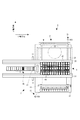
図1ないし図3に示すように、液滴吐出装置1は、石定盤に支持されたX軸支持ベース21上に配設され、主走査方向となるX軸方向に延在してワークWをX軸方向に移動させるX軸テーブル2と、複数本の支柱11を介してX軸テーブル2を跨ぐように架け渡された1対のY軸支持ベース31上に配設され、副走査方向となるY軸方向に延在するY軸テーブル3と、Y軸テーブル3に移動自在に吊設され、複数(12個)の機能液滴吐出ヘッド13が搭載された13個のキャリッジユニット4と、から構成されている。さらに、液滴吐出装置1は、これらの装置を、温度および湿度が管理された雰囲気内に収容するチャンバ5と、チャンバ5を貫通して、機能液滴吐出ヘッド13に機能液を供給する機能液供給ユニット6と、を備えており、チャンバ5の側壁の一部には、機能液供給ユニット6の主要部を為すメインタンク60等を収納するタンクキャビネット50が設けられている。液滴吐出装置1は、X軸テーブル2およびY軸テーブル3の駆動と同期して機能液滴吐出ヘッド13を吐出駆動させることにより、機能液供給ユニット6から供給された6色の機能液滴を吐出させ、ワークWに所定の描画パターンが描画される。
As shown in FIGS. 1 to 3, the
また、液滴吐出装置1は、フラッシングユニット15、吸引ユニット16、ワイピングユニット17、吐出性能検査ユニット18から成るメンテナンス装置7を備えており、これらユニットを機能液滴吐出ヘッド13の保守に供して、機能液滴吐出ヘッド13の機能維持・機能回復を図るようになっている。本実施形態の液滴吐出装置1では、X軸テーブル2とY軸テーブル3とが交わる部分にキャリッジユニット4を臨ませてワークWの描画を行い、Y軸テーブル3とメンテナンス装置7(吸引ユニット16、ワイピングユニット17)が交わる部分にキャリッジユニット4を臨ませて、機能液滴吐出ヘッド13の機能維持・機能回復を行う。
The
図2および図3に示すように、X軸テーブル2は、ワークWを吸着セットすると共にθ軸方向に補正可能な機構を有するセットテーブル22と、セットテーブル22をX軸方向にスライド自在に支持するX軸第1スライダ23と、上記のフラッシングユニット15および吐出性能検査ユニット18をX軸方向にスライド自在に支持するX軸第2スライダ24と、X軸方向に延在し、X軸第1スライダ23およびX軸第2スライダ24をX軸方向に移動させる左右一対のX軸リニアモータ(図示省略)と、を備えている。
As shown in FIGS. 2 and 3, the X-axis table 2 has a set table 22 having a mechanism capable of sucking and setting the workpiece W and correcting in the θ-axis direction, and the set table 22 slidably supported in the X-axis direction. An X-axis
Y軸テーブル3は、13個のキャリッジユニット4をそれぞれ吊設した13個のブリッジプレート32と、13個のブリッジプレート32を両持ちで支持する13組のY軸スライダ(図示省略)と、一対のY軸支持ベース31上に設置され、ブリッジプレート32をY軸方向に移動させる一対のY軸リニアモータ(図示省略)と、を備えている。また、Y軸テーブル3は、各キャリッジユニット4を介して描画時に機能液滴吐出ヘッド13を副走査するほか、機能液滴吐出ヘッド13を吸引ユニット16およびワイピングユニット17に臨ませる。この場合、各キャリッジユニット4を独立させて個別に移動させることも可能であるし、13個のキャリッジユニット4を一体として移動させることも可能である。なお、請求項に言う描画手段とは、X軸テーブル2、Y軸テーブル3およびキャリッジユニット4(機能液滴吐出ヘッド13およびヘッドユニット42)から構成されている。
The Y-axis table 3 includes 13
各キャリッジユニット4は、R・G・B・C・M・Yの6色、各2個(計12個)の機能液滴吐出ヘッド13と、12個の機能液滴吐出ヘッド13を6個ずつ2群に分けて支持するヘッドプレート41と、から成るヘッドユニット42を備えている(図4参照)。また、各キャリッジユニット4は、ヘッドユニット42をθ補正(θ回転)可能に支持するθ回転機構43と、θ回転機構43を介して、ヘッドユニット42をブリッジプレート32に支持させる吊設部材44と、を備えている。加えて、各キャリッジユニット4は、その上部にサブタンク45が配設されており(実際には、ブリッジプレート32上に配設)、このサブタンク45から自然水頭を利用し、かつ圧力調整弁(図示省略)を介して各機能液滴吐出ヘッド13に機能液が供給されるようになっている。なお、本実施形態においては、キャリッジユニット4の個数および各キャリッジユニット4に搭載される機能液滴吐出ヘッド13の個数は任意である。
Each carriage unit 4 has six colors of R, G, B, C, M, and Y, each of two (total 12) functional droplet ejection heads 13 and 12 functional droplet ejection heads 13 The
図5に示すように、機能液滴吐出ヘッド13は、いわゆる2連のインクジェットヘッドであり、2連の接続針54を有する機能液導入部51と、機能液導入部51に連なる2連のヘッド基板52と、ヘッド基板52の下方に連なり機能液を吐出するヘッド本体53と、を備えている(図5(a)参照)。
As shown in FIG. 5, the functional liquid
機能液導入部51は、一対の接続針54を有しており、サブタンク45から機能液の供給を受けるようになっている。また、ヘッド本体53は、ピエゾ素子等で構成される2連のポンプ部55と、複数の吐出ノズル57が形成されたノズル面58を有するノズルプレート56と、を有している。ノズルプレート56のノズル面58に形成された多数の吐出ノズル57は、相互に平行且つ半ノズルピッチ位置ズレして列設された2列のノズル列NLを構成しており、各ノズル列NLは、等ピッチで並べた180個の吐出ノズル57で構成されている(図5(b)参照)。ヘッド基板52には、2連のコネクタ59が設けられており、各コネクタ59は、フレキシブルフラットケーブル(図示省略)を介して上記の制御装置に接続されている。そして、この制御装置から出力された駆動波形が各コネクタ59を介して各ポンプ部55(圧電素子)に印加されることで、各吐出ノズル57から機能液が吐出される。
The functional
図1ないし図3に示すように、フラッシングユニット15は、一対の描画前フラッシングユニット61,61と、定期フラッシングユニット62とを有し、描画処理直前や、ワークWの載換え時等の描画処理休止時に行われる、機能液滴吐出ヘッド13の捨て吐出を受ける。吸引ユニット16は、13台のキャップユニット71を有し、各機能液滴吐出ヘッド13の吐出ノズル57から機能液を強制的に吸引すると共に、キャッピングを行う。ワイピングユニット17は、吸引後の機能液滴吐出ヘッド13のノズル面58を拭取る。吐出性能検査ユニット18は、機能液滴吐出ヘッド13の吐出の有無および飛行曲りを検査する。
As shown in FIGS. 1 to 3, the
定期フラッシングユニット62は、機能液を受ける定期フラッシングボックス64と、上記のX軸第2スライダ24に搭載され、定期フラッシングユニット62の両端を高さ調整可能に支持する一対のボックス支柱部材65と、を有している。定期フラッシングユニット62は、ワークWの載換え時等のように、描画処理を一時的に休止される時に、ヘッドユニット42の全機能液滴吐出ヘッド13を吐出駆動して行われる定期フラッシングの機能液を受けるためのものである。これにより、描画休止時の機能液滴吐出ヘッド13の乾燥およびノズル詰まりを防止することができる。
The
描画前フラッシングユニット61は、機能液を受ける一対の描画前フラッシングボックス63と、一対の各描画前フラッシングボックス63をセットテーブル22に支持させる一対のボックス支持部材(図示省略)と、で構成されている。描画前フラッシングユニット61は、ワークWに機能液を吐出させる直前にヘッドユニット42の全機能液滴吐出ヘッド13を吐出駆動して行う、描画前フラッシングの機能液を受けるためのものである。これにより、描画直前の機能液滴吐出ヘッド13の吐出を安定させることができ、ワークWに対して精度良い描画処理を行うことができる。
The
次に、図6および図7を参照して、吸引ユニット(吸引装置)16について詳細に説明する。吸引ユニット16は、12個の機能液滴吐出ヘッド13に対応する12個のヘッドキャップ81をキャッププレート82に配置した13台のキャップユニット71と、支持部材83を介して各キャップユニット71を昇降させる13台の昇降機構(離接機構)73と、各キャップユニット71に連なると共に機能液の吸引流路を有する13個の吸引流路系74(図8参照)と、各吸引流路系74に連なると共に2つの圧力水準に対応した2つの廃液タンク101を有する吸引機構75(図8参照)と、を備えている。また、吸引ユニット16は、後述する圧力制御機構102等に制御用の圧縮エアーを供給する圧縮エアー供給設備76と、各部から排気を行うための排気設備77と、廃液タンク101に接続され、貯留された機能液を廃液する機能液廃液設備78と、を備えている。
Next, the suction unit (suction device) 16 will be described in detail with reference to FIGS. 6 and 7. The
図7に示すように、キャップユニット71は、各色2個、計12個の機能液滴吐出ヘッド13に対応したヘッドキャップ81と、これらを搭載したキャッププレート82と、から成り、12個のヘッドキャップ81は、12個の機能液滴吐出ヘッド13と同じ並びで且つ同じ傾き姿勢で、キャッププレート82に搭載されている。
As shown in FIG. 7, the
図6に示すように、昇降機構73は、支持部材83を介してヘッドキャップ81を直接昇降させる昇降シリンダ84と、昇降シリンダ84による昇降をガイドする一対のリニアガイド85と、これらを支持するベース部86と、を有している。支持部材83は、上端にキャップユニット71を支持する支持フレーム72を有する支持部材本体87と、12個のヘッドキャップ81の大気開放弁(図示省略)を一括して開放するための大気開放フレーム88と、大気開放フレーム88を下動させる一対のエアーシリンダ89,89と、を有している。昇降機構73は、吸引用の密接位置と、フラッシング用の離間位置と、ヘッドユニット42の交換やキャップユニット71の消耗品交換(メンテナンス)用の交換位置との間でキャップユニット71を3段階に昇降させる。
As shown in FIG. 6, the
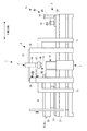
図8に示すように、各吸引流路系74は、各キャップユニット71に連なるキャップ側流路系90と、キャップ側流路系90に連なるタンク側流路系91と、から構成されている。キャップ側流路系90は、上流端を各ヘッドキャップ81に接続した同種流路92と、同種流路92の下流側を合流継手108を介して機能液の色別に合流させた個別吸引流路93と、合流させた個別吸引流路93の下流端が接続される一次マニホールド94と、から構成されている。すなわち、上記の6色、各2個(計12個)の機能液滴吐出ヘッド13に対応する12個のヘッドキャップ81に接続された各2本の同種流路92が合流継手108を介して合流し、計6本の個別吸引流路93に接続され、この6本の個別吸引流路93が、その各下流端で一次マニホールド94に接続されている。また、下流側において合流した個別吸引流路93には、機能液の色別に個別吸引流路93を開閉する個別流路開閉バルブ95が介設されている。
As shown in FIG. 8, each suction
タンク側流路系91は、上流端を一次マニホールド94に接続した複数の分配吸引流路96と、複数の分配吸引流路96の下流端が接続した2つの二次マニホールド97と、上流端を各二次マニホールド97に接続し、下流端を各廃液タンク101に接続した主吸引流路98と、から構成されている。また、分配吸引流路96は、2つの圧力水準に対応して、各キャップユニット71当たり、2本ずつ接続されており、各分配吸引流路96には、2つの圧力水準を選択的に切り換える分配流路開閉バルブ99が介設されている。各主吸引流路98には、各廃液タンク101に流入する機能液の流量を検出する流量計(流量検出手段)100が介設されており、主吸引流路98の下流端は、廃液タンク101の底面近傍まで深く挿入されている。なお、個別流路開閉バルブ95および分配流路開閉バルブ99は、単なる開閉弁であり、一方を「開」、他方を「閉」とすることで、流路切換えができるものである。
The tank-
一次マニホールド94および二次マニホールド97は、上端を円板状の蓋体により閉塞されたロート状に形成された円盤状マニホールドで構成されている。この場合、一次マニホールド94では、6本の個別吸引流路93の下流端が、円盤状マニホールドの周方向に均等配置するように、蓋体に接続されている。同様に、二次マニホールド97では、13本の分配吸引流路96の下流端は、円盤状マニホールドの周方向に均等配置するように、或いは周方向に2重に且つ均等配置するように蓋体に接続されている。
The
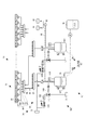
吸引機構75は、吸引した機能液を廃液する2つの廃液タンク101と、各廃液タンク101の内部圧力を制御する一対の圧力制御機構102と、を備えており、圧力制御機構102により、廃液タンク101の内部圧力が個別に調整され、分配吸引流路96を介して各ヘッドキャップ81が負圧(吸引)に制御される。
The suction mechanism 75 includes two
廃液タンク101は、高圧(第1水準)で使用する第1廃液タンク103と、低圧(第2水準)で使用する第2廃液タンク104とで構成されている。両タンク103,104は、いわゆる密閉タンクで構成されたタンク本体105と、タンク本体105の上部空間に接続され、内部圧力を検出する圧力計(圧力検出手段)106と、タンク本体105の側方に配設され、貯留された機能液の液位を検出する液位検出手段107と、を備えている。液位検出手段107は、上限液位を検出すると、機能液廃液設備78側の流路に介設された廃液開閉弁79を開放し機能液廃液設備78に機能液を廃液する。一方、下限液位を検出すると、廃液開閉弁79を閉弁する。また、廃液タンク101には、貯留した機能液を廃液する機能液廃液設備78が接続されている。さらに、第2廃液タンク104には、上記した定期フラッシングユニット62および描画前フラッシングユニット61が、フラッシング流路66を介して接続されている。なお、フラッシング流路66は、流路切替バルブ67を介して第1廃液タンク103および第2廃液タンク104の両タンクに、それぞれ接続されていてもよい(図8中の2点鎖線参照)。
The
圧力制御機構102は、上流側をタンク本体105の上部空間に接続した連通流路109と、連通流路109、圧縮エアー供給設備76および排気設備77に接続されたエジェクタ110と、エジェクタ110と圧縮エアー供給設備76の間の流路に介設され、エジェクタ110に供給される圧縮エアーの圧力を調整する電空レギュレータ(圧力調整手段)111と、電空レギュレータ111に隣接して介設された流量センサ112と、を備えている。すなわち、エジェクタ110は、圧縮エアー供給設備76から一次側に圧縮エアーを導入すると共に、二次側を廃液タンク101の上部空間に接続している。電空レギュレータ111により圧力が調整され、エジェクタ110に供給された圧縮エアーの随伴流によって、連通流路109中のエアーが排気設備77側に引っ張られる形で、タンク本体105の内部が減圧制御される。これにより、各廃液タンク101は、圧力制御機構102により個別に適正吸引圧力に圧力調整される。
The
ここで、適正吸引圧力の算出方法について説明する。圧力制御機構102による適正吸引圧力は、分配流路開閉バルブ99の開放数および圧力計106の検出値に基づいて行われる。分配流路開閉バルブ99の開放数から、予め実験で得られた係数テーブルにより適正吸引圧力を求める。その後、圧力計106により検出した廃液タンク101の圧力が適正吸引圧力となるように電空レギュレータ111を制御する(フィードバック制御)。
Here, a method for calculating the appropriate suction pressure will be described. The appropriate suction pressure by the
このように、分配流路開閉バルブ99の開放数に応じて、電空レギュレータ111を制御することで、各キャップユニット71(ヘッドキャップ81)における吸引圧力を一定にすることができる。これにより、吸引処理を行う機能液滴吐出ヘッド13の数に関係なく、各キャップユニット71(ヘッドキャップ81)の吸引流量を一定量とすることができる。また、圧力計106の検出値に基づいて電空レギュレータ111を制御することにより、いずれのキャップユニット71(ヘッドキャップ81)においても、吸引圧力が常に一定になるように制御することができる。なお、係数テーブルは、ヘッドキャップ81の数に加え、機能液の粘性に基づいて適正吸引圧力が設定されていることが好ましい。
As described above, by controlling the
なお、上記吸引処理例では、制御方法として、圧力計106の検出値に基づいて、電空レギュレータ111を制御する方法を用いたが、次のような制御方法を用いても良い。他の制御方法では、流量計100を用いて電空レギュレータ111の制御を行う。適正流量を求め、廃液タンク101に流入する機能液流量が適正流量になるよう電空レギュレータ111の圧力制御を調整する(フィードバック制御)。この構成によれば、流量計100に基づいて電空レギュレータ111の制御をすることにより、圧力計106を用いた場合と同様、いずれのキャップユニット71(ヘッドキャップ81)においても、吸引圧力が常に一定になるように制御することができ、機能液の種別を考慮しつつ機能液滴吐出ヘッド13に対する吸引処理を適切に行うことができる。
In the above suction processing example, the method of controlling the
次に、図9を参照して、液滴吐出装置1の主制御系について説明する。同図に示すように、液滴吐出装置1は、ヘッドユニット42を有する液滴吐出部191と、X軸テーブル2を有し、ワークWをX軸方向へ移動させるためのワーク移動部192と、Y軸テーブル3を有し、ヘッドユニット42をY軸方向へ移動させるヘッド移動部193と、メンテナンス装置7の各ユニットを有するメンテナンス部194と、機能液供給ユニット6を有し、機能液滴吐出ヘッド13に機能液を供給する機能液供給部198と、各種センサを有し、各種検出を行う検出部195と、各部を駆動制御する各種ドライバを有する駆動部196と、各部に接続され、液滴吐出装置1全体の制御を行う制御部(制御手段)197と、を備えている。
Next, the main control system of the
制御部197には、各手段を接続するためのインタフェース201と、一時的に記憶可能な記憶領域を有し、制御処理のための作業領域として使用されるRAM202と、各種記憶領域を有し、制御プログラムや制御データを記憶するROM203と、ワークWに所定の描画パターンを描画するための描画データや、各手段からの各種データ等を記憶すると共に、各種データを処理するためのプログラム等を記憶するハードディスク204と、ROM203やハードディスク204に記憶されたプログラム等に従い、各種データを演算処理するCPU205と、これらを互いに接続するバス206と、が備えられている。
The
そして、制御部197は、各手段からの各種データを、インタフェース201を介して入力すると共に、ハードディスク204に記憶されたプログラムに従ってCPU205に演算処理させ、その処理結果を、駆動部196を介して各手段に出力する。これにより、装置全体が制御され、液滴吐出装置1の各種処理が行われる。
Then, the
また、本実施形態において制御部197は、上記の圧力制御機構102を介して、第1廃液タンク103および第2廃液タンク104を、前者を高圧吸引とし後者を低圧吸引として、固定的に運転させる場合と、第1廃液タンク103および第2廃液タンク104を、高圧・低圧の交互運転させる場合と、の2種類の運転方法を実施できるようになっている。この場合の交互運転は、一方のタンクのメンテナンス等、必要に応じて実施する場合と、所定の運転時間や所定のワーク処理枚数等を基準に定期的に実施する場合等がある。
Further, in the present embodiment, the
ここで、上記した適正吸引圧力を用い、上記した吸引ユニット16による第1の機能液の吸引処理について説明する。この吸引処理は、機能液滴吐出ヘッド13に機能液を初期充填する際の吸引シークエンスであり、初期段階では高圧(第1水準)で吸引し、終期段階では低圧(第2水準)で吸引して機能液を充填するものである。ここでは、全キャリッジユニット4に対して、高圧で吸引した後、低圧で吸引する場合を例に挙げて説明する。
Here, using the above-described appropriate suction pressure, the first functional liquid suction processing by the above-described
まず、対応するキャップユニット71を昇降機構73により密接位置に上昇させ、分配流路開閉バルブ99を制御して、キャップユニット71と、第1廃液タンク103と、を連通させる。そして、高圧および低圧の両圧力制御機構102を駆動させ、高圧で初期充填を開始する。
First, the
高圧による吸引後、第1廃液タンク103に接続した分配流路開閉バルブ99を「閉」にすると共に、第2廃液タンク104に接続した分配流路開閉バルブ99を「開」にする。これにより、キャップユニット71と第2廃液タンク104とを連通させ、低圧での充填を行なう。
After suction by high pressure, the distribution flow path opening / closing
このように、2つの分配流路開閉バルブ99,99を切換えることにより、主吸引流路98を任意の1の廃液タンク101に選択的に流路切換えすることで、複数のキャップユニット71をキャップユニット71単位で、相互に吸引圧力が異なる廃液タンク101と連通させることができる。これにより、分配流路開閉バルブ99を制御するだけで、吸引する圧力を高圧から低圧に切換えることができる。したがって、圧力水準が1つの場合と比して、高圧から低圧に切換えた際の圧力の安定待ち時間を短縮することができる。
In this way, by switching the two distribution flow path opening /
次に、上記した吸引ユニット16による第2の機能液の吸引処理について説明する。この吸引処理は、吸引圧力を同一水準として、各吸引機構75を交互に使用して機能液滴吐出ヘッド13から機能液を吸引するものである。ここでは、奇数番号の各ヘッドユニット42を第1廃液タンク103に吸引した後に、偶数番号の各ヘッドユニット42を第2廃液タンク104に吸引する場合について説明する。まず、分配流路開閉バルブ99を制御して、奇数番号のヘッドキャップ81と、第1廃液タンク103と、を連通させて吸引する。
Next, the suction process of the second functional liquid by the
奇数番号のヘッドユニット42から機能液を吸引後、第1廃液タンク103に接続した分配流路開閉バルブ99を「閉」にし、第2廃液タンク104に接続した分配流路開閉バルブ99を「開」にすると共に、奇数番号のヘッドユニット42に対応する個別流路開閉バルブ95を「閉」にすると共に、偶数番号のヘッドユニット42に対応する個別流路開閉バルブ95を「開」にする。これにより、偶数番号のヘッドユニット42と、第2廃液タンク104と、を連通させて吸引する。例えば、第2廃液タンク104を有する吸引機構75で吸引処理を実行している間に、第1廃液タンク103が満水であれば、第1廃液タンク103に貯留した廃液(機能液)を廃棄することができる。したがって、吸引機構75が1つの場合には、吸引処理を一時停止させて、廃液を廃棄し、再度吸引する必要があったが、本実施形態では、吸引処理を止めることなく、吸引処理を続行することができるため、吸引処理の時間を短縮することができる。また、同一水準の圧力で交互に吸引することで、第1廃液タンク103および第2廃液タンク104の廃液の貯留量を等しくすることができる。
After sucking the functional liquid from the odd-numbered
最後に、上記した吸引ユニット16による第3の機能液の吸引処理について説明する。この吸引処理は、吸引ユニット16による吸引と、フラッシング用の吸引と、を同時に行うものである。なお、吸引用の吸引は高圧で行い、フラッシング用の吸引は低圧で行う。ここでは、5個のキャリッジユニット4に対しフラッシングを行い、残りの8個のキャリッジユニット4に対し吸引を行う場合を例に挙げて説明する。
Finally, the third functional liquid suction process by the
吸引用の吸引処理を行うキャリッジユニット4では、対応するキャップユニット71を昇降機構73により、密接位置に上昇させ、分配流路開閉バルブ99を制御して、キャップユニット71と、第1廃液タンク103とを連通させる。フラッシング用の吸引処理を行うキャリッジユニット4では、対応するキャップユニット71を昇降機構73により、離間位置に上昇させ、分配流路開閉バルブ99を制御して、ヘッドキャップ81と、第2廃液タンク104を連通させる。これらの状態で、同時並行吸引処理を行う。このように、一対の分配流路開閉バルブ99の制御により、複数のキャップユニット71に対し、同時並行的に異なる吸引圧力による吸引処理を行うことができる。また、各吸引機構75は、複数のキャップユニット71の吸引処理を行う構成であるため、キャップユニット71単位で吸引手段を設ける場合に比して、その数を少なくすることができ、スペース効率の向上および構造の単純化を図ることができる。
In the carriage unit 4 that performs suction processing for suction, the
そして、この第3の機能液の吸引処理においても、例えば、1日置きに第1廃液タンク103および第2廃液タンク104を、高圧・低圧の交互運転とし、第1廃液タンク103および第2廃液タンク104の廃液の貯留量を等しくすることが、好ましい。また、この交互運転に対応すべく、フラッシングユニット15のフラッシング流路66が、流路切替バルブ67を介して第1廃液タンク103および第2廃液タンク104の両タンクに、それぞれ接続されていることが好ましい。流路切替バルブ67には、任意の1のフラッシング流路66を選択可能な流路切替機構が備わっており、圧力水準に変更(パターン設定の変更)があっても、フラッシングユニット15が、圧力水準が低い廃液タンク101に接続されるように切り替えられる。
In the third functional liquid suction process, for example, the first waste liquid tank 103 and the second waste liquid tank 104 are alternately operated at high pressure and low pressure every other day, so that the first waste liquid tank 103 and the second waste liquid are operated. It is preferable to equalize the amount of waste liquid stored in the tank 104. In order to cope with this alternate operation, the
なお、上記した2種類の吸引処理のように、ヘッドユニット42毎に吸引処理を行うことも可能であるが、吸引する機能液滴吐出ヘッド13毎に行うことも可能である。なお、この場合、ヘッドキャップ81は、キャップユニット71単位で機能液滴吐出ヘッド13と離接するため、個別吸引流路93に設けられた個別流路開閉バルブ95を制御することで、任意の機能液滴吐出ヘッド13のみに対して、吸引処理することができる。さらに、吸引機構75(廃液タンク101)を、高圧および低圧の他、中圧等、必要に応じ複数で構成してもよい。
Note that, as in the above-described two types of suction processing, the suction processing can be performed for each
また、本実施形態においては、R(レッド)、G(グリーン)、B(ブルー)、C(シアン)、M(マゼンダ)、Y(イエロー)の6色の機能液が供給される機能液滴吐出ヘッド13を用いたものを使用しているが、供給される機能液の色数、色種は任意である。
In the present embodiment, functional liquid droplets supplied with six functional liquids of R (red), G (green), B (blue), C (cyan), M (magenta), and Y (yellow) are supplied. Although the one using the
以上の構成によれば、上述したように、様々な吸引処理に柔軟に対応することができる。また、キャップユニット71ごとに吸引機構75を設ける場合に比して、吸引機構75の数を少なくすることができ、スペース効率の向上および構造の単純化を図ることができる。さらに、機能液滴吐出ヘッド13の数(ヘッドキャップ81の数)の増加や、ヘッドユニット42の数の増加に対しても、吸引機構75に大きな変更を加えることなく柔軟に対応することができる。
According to the above configuration, various suction processes can be flexibly handled as described above. Further, the number of suction mechanisms 75 can be reduced as compared with the case where the suction mechanisms 75 are provided for each
1:液滴吐出装置、13:機能液滴吐出ヘッド、15:フラッシングユニット、16:吸引ユニット、58:ノズル面、71:キャップユニット、76:圧縮エアー供給設備、81:ヘッドキャップ、93:個別吸引流路、94:一次マニホールド、95:個別流路開閉バルブ、96:分配吸引流路、97:二次マニホールド、98:主吸引流路、99:分配流路開閉バルブ、100:流量計、101廃液タンク、103:第1廃液タンク、104:第2廃液タンク、106:圧力計、110:エジェクタ、111:電空レギュレータ、W:ワーク 1: droplet ejection device, 13: functional droplet ejection head, 15: flushing unit, 16: suction unit, 58: nozzle surface, 71: cap unit, 76: compressed air supply equipment, 81: head cap, 93: individual Suction channel, 94: primary manifold, 95: individual channel switching valve, 96: distribution suction channel, 97: secondary manifold, 98: main suction channel, 99: distribution channel switching valve, 100: flow meter, 101 waste liquid tank, 103: first waste liquid tank, 104: second waste liquid tank, 106: pressure gauge, 110: ejector, 111: electropneumatic regulator, W: work
Claims (13)
機能液別の複数種の前記機能液滴吐出ヘッドに対応する機能液別の複数種のキャップを搭載したキャップユニットと、
前記各キャップを、前記キャップユニット単位で離接動作させる離接機構と、
前記キャップユニット単位で前記各キャップから機能液を吸引すると共に、各々吸引圧力が異なる複数台の吸引手段と、
上流側を前記各キャップに接続された複数の個別吸引流路と、
下流側を前記各吸引手段に接続された複数の主吸引流路と、
前記複数の個別吸引流路と前記複数の主吸引流路との間に介設され、前記複数の個別吸引流路を合流させると共に、合流後の流路を前記複数の主吸引流路に対し選択的に連通させる合流流路系と、を備えたことを特徴とする吸引装置。 A suction device for sucking a functional liquid by separating from and contacting the nozzle surface of a plurality of types of ink jet type functional liquid droplet discharge heads for each functional liquid,
A cap unit equipped with a plurality of types of caps for each functional liquid corresponding to the plurality of types of functional liquid droplet ejection heads for each functional liquid;
Separation / contact mechanism for separating / connecting each cap in units of cap units;
While sucking the functional liquid from each cap in units of the cap unit, a plurality of suction means each having a different suction pressure;
A plurality of individual suction channels connected to the caps on the upstream side;
A plurality of main suction channels connected to the suction means on the downstream side;
The plurality of individual suction flow paths and the plurality of main suction flow paths are interposed, and the plurality of individual suction flow paths are merged, and the merged flow paths are defined with respect to the plurality of main suction flow paths. And a merging channel system that selectively communicates with the suction device.
機能液別のm種の前記機能液滴吐出ヘッドに対応する機能液別のm種のキャップをキャッププレートに組み込んだ、前記n台のヘッドユニットに対応するn台のキャップユニットと、
前記キャッププレートを介して前記各キャップを、前記キャップユニット単位で離接動作させる離接機構と、
前記キャップユニット単位で前記各キャップから機能液を吸引すると共に、各々吸引圧力が異なるp台(pは複数)の吸引手段と、
上流側を前記各キャップに接続されたm×n本の個別吸引流路と、
下流側を前記各吸引手段に接続されたp本の主吸引流路と、
前記m×n本の個別吸引流路と前記p本の主吸引流路との間に介設され、前記m×n本の個別吸引流路を合流させると共に、合流後の流路を前記p本の主吸引流路に対し選択的に連通させる合流流路系と、を備えたことを特徴とする吸引装置。 M types (m is a plurality) of ink jet type functional droplet discharge heads for each functional liquid are provided corresponding to n units (n is a plurality) of head units mounted on a carriage. A suction device that separates and contacts the nozzle surface to suck the functional liquid,
N cap units corresponding to the n head units, wherein m types of caps corresponding to functional liquids corresponding to m types of functional liquid droplet ejection heads are incorporated in a cap plate;
Separation / contact mechanism for separating / contacting each cap through the cap plate in units of the cap unit;
While sucking the functional liquid from the caps in units of the cap unit, each of the p units (p is a plurality) of suction means having different suction pressures;
M × n individual suction channels connected to the caps on the upstream side;
P main suction channels connected to the respective suction means on the downstream side;
The m × n individual suction flow paths and the p main suction flow paths are interposed between the m × n individual suction flow paths and merge the m × n individual suction flow paths. And a merging channel system for selectively communicating with the main suction channel of the book.
前記m×n本の個別吸引流路を、前記キャップユニット単位で合流させるn台の一次マニホールドと、
前記各主吸引流路の上流側が接続されたp台の二次マニホールドと、
前記n台の一次マニホールドと前記p台の二次マニホールドとを個々に接続するn×p本の分配吸引流路と、
前記各分配吸引流路に介設したn×p個の分配流路開閉バルブと、を有していることを特徴とする請求項2に記載の吸引装置。 The merging channel system is
N primary manifolds for merging the m × n individual suction flow paths in units of the cap units;
P secondary manifolds connected to the upstream side of each main suction channel;
N × p distribution suction channels for individually connecting the n primary manifolds and the p secondary manifolds;
The suction apparatus according to claim 2, further comprising n × p distribution flow path opening / closing valves interposed in the distribution suction flow paths.
これに対応する前記m種の各キャップは、同種の複数のもので構成され、
前記各個別吸引流路には、上流側に介設された分岐継手により分岐した同種流路を介して、前記同種の複数のキャップが接続されていることを特徴とする請求項2ないし4のいずれかに記載の吸引装置。 Each of the m kinds of functional liquid droplet ejection heads is composed of a plurality of the same kind,
Each of the m kinds of caps corresponding to this is composed of a plurality of the same kind,
The plurality of caps of the same type are connected to the individual suction channels through the same type of channels branched by a branch joint provided on the upstream side. The suction device according to any one of the above.
一次側に圧縮エアーを導入すると共に、二次側を前記各廃液タンクの上部空間に接続したエジェクタと、を有していることを特徴とする請求項1ないし5のいずれかに記載の吸引装置。 Each of the suction means includes a waste liquid tank connected to the downstream side of the main suction channel;
6. A suction device according to claim 1, further comprising: an ejector that introduces compressed air to the primary side and connects the secondary side to an upper space of each of the waste liquid tanks. .
前記圧力調整手段を制御する制御手段と、を更に有していることを特徴とする請求項6に記載の吸引装置。 Each of the suction means includes pressure adjusting means for adjusting the pressure of compressed air on the primary side,
The suction device according to claim 6, further comprising control means for controlling the pressure adjusting means.
前記各制御手段は、前記廃液タンク内の圧力が前記開放数に応じた所定の圧力になるように、前記圧力調整手段を制御することを特徴とする請求項8に記載の吸引装置。 Pressure detecting means for detecting the pressure of each waste liquid tank during suction, further comprising:
9. The suction device according to claim 8, wherein each of the control units controls the pressure adjusting unit so that the pressure in the waste liquid tank becomes a predetermined pressure corresponding to the number of opened.
前記各制御手段は、前記各廃液タンクに流入する機能液流量が前記開放数に応じた所定の流量になるように、前記圧力調整手段を制御することを特徴とする請求項8に記載の吸引装置。 A flow rate detecting means for detecting the flow rate of the functional liquid flowing into each of the waste liquid tanks by suction;
9. The suction according to claim 8, wherein each of the control units controls the pressure adjusting unit so that a flow rate of the functional liquid flowing into each of the waste liquid tanks becomes a predetermined flow rate corresponding to the open number. apparatus.
一方の前記吸引手段は、前記各キャップを前記各機能液滴吐出ヘッドに密接した状態で吸引するためのものであり、
他方の前記吸引手段は、前記各キャップを前記各機能液滴吐出ヘッドから離間させた状態で吸引するためのものであることを特徴とする請求項1ないし10のいずれかに記載の吸引装置。 The plurality of suction means is composed of two suction means,
One of the suction means is for sucking the caps in close contact with the functional liquid droplet ejection heads,
11. The suction device according to claim 1, wherein the other suction means is for sucking each cap in a state of being separated from each functional liquid droplet ejection head.
請求項1ないし11のいずれかに記載された吸引装置と、を備えたことを特徴とする液滴吐出装置。 A drawing means for performing drawing by discharging functional liquid droplets from each of the functional liquid droplet discharge heads while moving the plurality of functional liquid droplet discharge heads with respect to a workpiece;
A liquid droplet ejection apparatus comprising: the suction device according to claim 1.
前記フラッシング受容手段は、廃液配管を介して前記複数の吸引手段のうちのいずれかに接続されていることを特徴とする請求項12に記載の液滴吐出装置。 A plurality of flushing receiving means for receiving a discharge from the plurality of functional liquid droplet discharge heads;
13. The droplet discharge device according to claim 12, wherein the flushing receiving means is connected to any one of the plurality of suction means via a waste liquid pipe.
Priority Applications (1)
| Application Number | Priority Date | Filing Date | Title |
|---|---|---|---|
| JP2008176517A JP5292955B2 (en) | 2008-07-07 | 2008-07-07 | Suction device and droplet discharge device equipped with the same |
Applications Claiming Priority (1)
| Application Number | Priority Date | Filing Date | Title |
|---|---|---|---|
| JP2008176517A JP5292955B2 (en) | 2008-07-07 | 2008-07-07 | Suction device and droplet discharge device equipped with the same |
Related Child Applications (1)
| Application Number | Title | Priority Date | Filing Date |
|---|---|---|---|
| JP2013123535A Division JP5729420B2 (en) | 2013-06-12 | 2013-06-12 | Suction device and droplet discharge device equipped with the same |
Publications (2)
| Publication Number | Publication Date |
|---|---|
| JP2010012733A true JP2010012733A (en) | 2010-01-21 |
| JP5292955B2 JP5292955B2 (en) | 2013-09-18 |
Family
ID=41699312
Family Applications (1)
| Application Number | Title | Priority Date | Filing Date |
|---|---|---|---|
| JP2008176517A Expired - Fee Related JP5292955B2 (en) | 2008-07-07 | 2008-07-07 | Suction device and droplet discharge device equipped with the same |
Country Status (1)
| Country | Link |
|---|---|
| JP (1) | JP5292955B2 (en) |
Cited By (1)
| Publication number | Priority date | Publication date | Assignee | Title |
|---|---|---|---|---|
| JP2016043557A (en) * | 2014-08-22 | 2016-04-04 | セイコーエプソン株式会社 | Waste ink recovery unit, printer, and waste ink recover method |
Citations (12)
| Publication number | Priority date | Publication date | Assignee | Title |
|---|---|---|---|---|
| JPH1067121A (en) * | 1996-08-28 | 1998-03-10 | Fuji Xerox Co Ltd | Ink-jet type image forming apparatus |
| JPH10181034A (en) * | 1996-12-27 | 1998-07-07 | Canon Inc | Ink jet recording device |
| JP2000153622A (en) * | 1998-09-16 | 2000-06-06 | Seiko Epson Corp | Ink jet recorder and cleaning method suitable therefor |
| JP2001310487A (en) * | 2000-04-28 | 2001-11-06 | Ricoh Co Ltd | Apparatus for sustaining function of recording head and ink jet recorder comprising it |
| JP2003039704A (en) * | 2001-07-27 | 2003-02-13 | Seiko Epson Corp | Ink jet recorder |
| JP2003205636A (en) * | 2002-01-15 | 2003-07-22 | Brother Ind Ltd | Ink jet recorder |
| WO2003089246A1 (en) * | 2002-04-22 | 2003-10-30 | Seiko Epson Corporation | Method of cleaning print head |
| JP2004142332A (en) * | 2002-10-25 | 2004-05-20 | Canon Inc | Recovery process device of liquid discharge head, and image formation apparatus using the same |
| JP2005169235A (en) * | 2003-12-10 | 2005-06-30 | Seiko Epson Corp | Drop discharging device |
| JP2005254798A (en) * | 2004-02-13 | 2005-09-22 | Seiko Epson Corp | Liquid droplet discharging apparatus, manufacturing method for electro-optic apparatus, electro-optic apparatus and electronic apparatus |
| JP2006150639A (en) * | 2004-11-26 | 2006-06-15 | Hitachi Industries Co Ltd | Coating device |
| JP2006181900A (en) * | 2004-12-28 | 2006-07-13 | Fuji Photo Film Co Ltd | Inkjet recorder |
-
2008
- 2008-07-07 JP JP2008176517A patent/JP5292955B2/en not_active Expired - Fee Related
Patent Citations (12)
| Publication number | Priority date | Publication date | Assignee | Title |
|---|---|---|---|---|
| JPH1067121A (en) * | 1996-08-28 | 1998-03-10 | Fuji Xerox Co Ltd | Ink-jet type image forming apparatus |
| JPH10181034A (en) * | 1996-12-27 | 1998-07-07 | Canon Inc | Ink jet recording device |
| JP2000153622A (en) * | 1998-09-16 | 2000-06-06 | Seiko Epson Corp | Ink jet recorder and cleaning method suitable therefor |
| JP2001310487A (en) * | 2000-04-28 | 2001-11-06 | Ricoh Co Ltd | Apparatus for sustaining function of recording head and ink jet recorder comprising it |
| JP2003039704A (en) * | 2001-07-27 | 2003-02-13 | Seiko Epson Corp | Ink jet recorder |
| JP2003205636A (en) * | 2002-01-15 | 2003-07-22 | Brother Ind Ltd | Ink jet recorder |
| WO2003089246A1 (en) * | 2002-04-22 | 2003-10-30 | Seiko Epson Corporation | Method of cleaning print head |
| JP2004142332A (en) * | 2002-10-25 | 2004-05-20 | Canon Inc | Recovery process device of liquid discharge head, and image formation apparatus using the same |
| JP2005169235A (en) * | 2003-12-10 | 2005-06-30 | Seiko Epson Corp | Drop discharging device |
| JP2005254798A (en) * | 2004-02-13 | 2005-09-22 | Seiko Epson Corp | Liquid droplet discharging apparatus, manufacturing method for electro-optic apparatus, electro-optic apparatus and electronic apparatus |
| JP2006150639A (en) * | 2004-11-26 | 2006-06-15 | Hitachi Industries Co Ltd | Coating device |
| JP2006181900A (en) * | 2004-12-28 | 2006-07-13 | Fuji Photo Film Co Ltd | Inkjet recorder |
Cited By (1)
| Publication number | Priority date | Publication date | Assignee | Title |
|---|---|---|---|---|
| JP2016043557A (en) * | 2014-08-22 | 2016-04-04 | セイコーエプソン株式会社 | Waste ink recovery unit, printer, and waste ink recover method |
Also Published As
| Publication number | Publication date |
|---|---|
| JP5292955B2 (en) | 2013-09-18 |
Similar Documents
| Publication | Publication Date | Title |
|---|---|---|
| JP4561795B2 (en) | Suction device, droplet discharge device including the same, and method of manufacturing electro-optical device | |
| JP4438840B2 (en) | Suction device, suction system, and droplet discharge device equipped with these | |
| US9694583B2 (en) | Liquid ejection apparatus and moisturizing apparatus for liquid ejection head | |
| JP5343611B2 (en) | Pressure regulating valve and droplet discharge device provided with the same | |
| JP5729420B2 (en) | Suction device and droplet discharge device equipped with the same | |
| JP2008238125A (en) | Functional liquid supply device, liquid droplet discharge device, method of manufacturing electrooptical device, electrooptical device and electronic device | |
| JP5195473B2 (en) | Liquid absorption tank and liquid droplet ejection apparatus provided with the same | |
| JP5292955B2 (en) | Suction device and droplet discharge device equipped with the same | |
| JP5169550B2 (en) | Suction device control method, suction device, and droplet discharge device | |
| JP2005262879A (en) | Ink-jet head maintaining method and image forming apparatus | |
| JP2010201384A (en) | Suction device and droplet discharge apparatus equipped with the same | |
| JP5157948B2 (en) | Device failure evaluation method for suction device and device failure evaluation device for suction device | |
| JP5223518B2 (en) | Head cap, suction device, and droplet discharge device | |
| JP2005271584A (en) | Maintenance method for inkjet head, and image forming device | |
| JP5359340B2 (en) | Suction device and droplet discharge device equipped with the same | |
| JP6384069B2 (en) | Liquid ejection device | |
| JP5578250B2 (en) | Head cap, suction device, and droplet discharge device | |
| JP2010214353A (en) | Functional liquid packing container, functional liquid supply device and droplet discharge device with the container | |
| JP5417918B2 (en) | Functional liquid replacement method for liquid droplet ejection device and liquid droplet ejection device | |
| JP2010211045A (en) | Pressure control valve and droplet discharge device including the same | |
| JP2005193661A (en) | Maintenance method for inkjet head and image recording apparatus | |
| JP2016185498A (en) | Droplet discharge control device, droplet discharge control method and program | |
| JP5585704B2 (en) | Pressure regulating valve and droplet discharge device provided with the same | |
| JP2010029802A (en) | Method for exchanging functional liquid of functional liquid supply apparatus and droplet discharging apparatus | |
| JP2010022953A (en) | Deaeration mechanism and droplet-discharging device for liquid piping |
Legal Events
| Date | Code | Title | Description |
|---|---|---|---|
| RD03 | Notification of appointment of power of attorney |
Free format text: JAPANESE INTERMEDIATE CODE: A7423 Effective date: 20110316 |
|
| A621 | Written request for application examination |
Free format text: JAPANESE INTERMEDIATE CODE: A621 Effective date: 20110328 |
|
| RD04 | Notification of resignation of power of attorney |
Free format text: JAPANESE INTERMEDIATE CODE: A7424 Effective date: 20110512 |
|
| A131 | Notification of reasons for refusal |
Free format text: JAPANESE INTERMEDIATE CODE: A131 Effective date: 20120612 |
|
| A977 | Report on retrieval |
Free format text: JAPANESE INTERMEDIATE CODE: A971007 Effective date: 20120613 |
|
| A521 | Request for written amendment filed |
Free format text: JAPANESE INTERMEDIATE CODE: A523 Effective date: 20120808 |
|
| A131 | Notification of reasons for refusal |
Free format text: JAPANESE INTERMEDIATE CODE: A131 Effective date: 20130108 |
|
| A521 | Request for written amendment filed |
Free format text: JAPANESE INTERMEDIATE CODE: A523 Effective date: 20130308 |
|
| TRDD | Decision of grant or rejection written | ||
| A01 | Written decision to grant a patent or to grant a registration (utility model) |
Free format text: JAPANESE INTERMEDIATE CODE: A01 Effective date: 20130514 |
|
| A61 | First payment of annual fees (during grant procedure) |
Free format text: JAPANESE INTERMEDIATE CODE: A61 Effective date: 20130527 |
|
| R150 | Certificate of patent or registration of utility model |
Ref document number: 5292955 Country of ref document: JP Free format text: JAPANESE INTERMEDIATE CODE: R150 Free format text: JAPANESE INTERMEDIATE CODE: R150 |
|
| S531 | Written request for registration of change of domicile |
Free format text: JAPANESE INTERMEDIATE CODE: R313531 |
|
| R350 | Written notification of registration of transfer |
Free format text: JAPANESE INTERMEDIATE CODE: R350 |
|
| R250 | Receipt of annual fees |
Free format text: JAPANESE INTERMEDIATE CODE: R250 |
|
| S111 | Request for change of ownership or part of ownership |
Free format text: JAPANESE INTERMEDIATE CODE: R313113 |
|
| R360 | Written notification for declining of transfer of rights |
Free format text: JAPANESE INTERMEDIATE CODE: R360 |
|
| R360 | Written notification for declining of transfer of rights |
Free format text: JAPANESE INTERMEDIATE CODE: R360 |
|
| R371 | Transfer withdrawn |
Free format text: JAPANESE INTERMEDIATE CODE: R371 |
|
| R250 | Receipt of annual fees |
Free format text: JAPANESE INTERMEDIATE CODE: R250 |
|
| S111 | Request for change of ownership or part of ownership |
Free format text: JAPANESE INTERMEDIATE CODE: R313113 |
|
| R350 | Written notification of registration of transfer |
Free format text: JAPANESE INTERMEDIATE CODE: R350 |
|
| R250 | Receipt of annual fees |
Free format text: JAPANESE INTERMEDIATE CODE: R250 |
|
| R250 | Receipt of annual fees |
Free format text: JAPANESE INTERMEDIATE CODE: R250 |
|
| R250 | Receipt of annual fees |
Free format text: JAPANESE INTERMEDIATE CODE: R250 |
|
| R250 | Receipt of annual fees |
Free format text: JAPANESE INTERMEDIATE CODE: R250 |
|
| LAPS | Cancellation because of no payment of annual fees |