JP2010012003A - Grommet structure in incubator - Google Patents
Grommet structure in incubator Download PDFInfo
- Publication number
- JP2010012003A JP2010012003A JP2008174209A JP2008174209A JP2010012003A JP 2010012003 A JP2010012003 A JP 2010012003A JP 2008174209 A JP2008174209 A JP 2008174209A JP 2008174209 A JP2008174209 A JP 2008174209A JP 2010012003 A JP2010012003 A JP 2010012003A
- Authority
- JP
- Japan
- Prior art keywords
- grommet
- holding
- incubator
- longitudinal member
- pair
- Prior art date
- Legal status (The legal status is an assumption and is not a legal conclusion. Google has not performed a legal analysis and makes no representation as to the accuracy of the status listed.)
- Granted
Links
- QVGXLLKOCUKJST-UHFFFAOYSA-N atomic oxygen Chemical compound [O] QVGXLLKOCUKJST-UHFFFAOYSA-N 0.000 abstract description 11
- 229910052760 oxygen Inorganic materials 0.000 abstract description 11
- 239000001301 oxygen Substances 0.000 abstract description 11
- 230000007423 decrease Effects 0.000 description 3
- 230000000149 penetrating effect Effects 0.000 description 3
- 239000000758 substrate Substances 0.000 description 3
- 238000003780 insertion Methods 0.000 description 2
- 230000037431 insertion Effects 0.000 description 2
- 238000012423 maintenance Methods 0.000 description 2
- 244000043261 Hevea brasiliensis Species 0.000 description 1
- 206010036590 Premature baby Diseases 0.000 description 1
- 239000013013 elastic material Substances 0.000 description 1
- 238000012986 modification Methods 0.000 description 1
- 230000004048 modification Effects 0.000 description 1
- 229920003052 natural elastomer Polymers 0.000 description 1
- 229920001194 natural rubber Polymers 0.000 description 1
- 230000002093 peripheral effect Effects 0.000 description 1
- 229920005989 resin Polymers 0.000 description 1
- 239000011347 resin Substances 0.000 description 1
- 229920002050 silicone resin Polymers 0.000 description 1
- 229920002379 silicone rubber Polymers 0.000 description 1
- 239000004945 silicone rubber Substances 0.000 description 1
- 239000007787 solid Substances 0.000 description 1
- 229920003051 synthetic elastomer Polymers 0.000 description 1
- 229920003002 synthetic resin Polymers 0.000 description 1
- 239000000057 synthetic resin Substances 0.000 description 1
- 239000005061 synthetic rubber Substances 0.000 description 1
- 125000000391 vinyl group Chemical group [H]C([*])=C([H])[H] 0.000 description 1
- 229920002554 vinyl polymer Polymers 0.000 description 1
Images


Classifications
-
- A—HUMAN NECESSITIES
- A61—MEDICAL OR VETERINARY SCIENCE; HYGIENE
- A61G—TRANSPORT, PERSONAL CONVEYANCES, OR ACCOMMODATION SPECIALLY ADAPTED FOR PATIENTS OR DISABLED PERSONS; OPERATING TABLES OR CHAIRS; CHAIRS FOR DENTISTRY; FUNERAL DEVICES
- A61G11/00—Baby-incubators; Couveuses
-
- A—HUMAN NECESSITIES
- A61—MEDICAL OR VETERINARY SCIENCE; HYGIENE
- A61G—TRANSPORT, PERSONAL CONVEYANCES, OR ACCOMMODATION SPECIALLY ADAPTED FOR PATIENTS OR DISABLED PERSONS; OPERATING TABLES OR CHAIRS; CHAIRS FOR DENTISTRY; FUNERAL DEVICES
- A61G11/00—Baby-incubators; Couveuses
- A61G11/009—Baby-incubators; Couveuses with hand insertion windows, e.g. in the walls
Abstract
Description
本発明は、保育器のフードに設けられたグロメット取り付け部と、このグロメット取り付け部に取り付けられたグロメット部材とを備え、上記グロメット部材が酸素供給用チューブなどの長手状部材を貫通させた状態で保持するための切れ目を有する、保育器におけるグロメット構造に関するものであって、開放型保育器兼用の閉鎖型保育器に適用するのに最適なものである。 The present invention comprises a grommet mounting portion provided on a hood of an incubator and a grommet member mounted on the grommet mounting portion, with the grommet member penetrating a longitudinal member such as an oxygen supply tube. The present invention relates to a grommet structure in an incubator having a cut for holding, and is optimal for application to a closed incubator that also serves as an open type incubator.
保育器のフードに設けられたグロメット取り付け部と、このグロメット取り付け部に取り付けられたグロメット部材とを備え、上記グロメット部材が酸素供給用チューブなどの長手状部材を貫通させた状態で保持するための切れ目を有する、保育器におけるグロメット構造は、例えば特許文献1に開示されているように、従来から知られている。また、この特許文献1に開示されているグロメット構造に用いられているグロメット部材は、このグロメット部材の外周囲(ただし、上縁部を除く外周囲全体)に沿って上記グロメット部材に設けられている厚さが比較的大きいほぼU字形状の被取り付け部を備えている。そして、このほぼU字形状の被取り付け部は、保育器のフードのグロメット取り付け部に取り付けられる。また、上記グロメット部材のうちの、このほぼU字形状の被取り付け部に囲まれている部分は、厚さが比較的小さくて、ケーブル類保持部を構成している。なお、本文において、「ケーブル類」とは、保育器において用いられる酸素マスクなどの各種の器具のための一本の、もしくは、同径または異径の複数本が束ねられた状態(複数本の束が蛇腹状などの外被チューブによって被覆されている場合も含む。)のチューブ、ケーブル、電気コードなどの各種の長手状部材を意味している。
さらに、特許文献1のグロメット部材のケーブル類保持部には、この保持部の上端から下端部付近までほぼ縦方向に延在している一本の縦型の切れ目と、この縦型の切れ目とそれぞれほぼ直交するようにほぼ横方向に延在している複数本の横型の切れ目とから成るケーブル類保持用の切れ目が形成されている。そして、ケーブル類をグロメット部材のケーブル類保持部に保持させるときには、ケーブル類の適当箇所を縦型の切れ目に上方から当てがってこの縦型の切れ目に押し込むように下方に移動させると、ケーブル類は、この縦型の切れ目と上記横型の切れ目とが交差するほぼ十文字形状の交差部位に導入される。そして、ケーブル類は、ケーブル類保持部のうちの、この交差部位を構成している4枚の保持片部によって、この交差部位付近に弾性的に位置保持される。
しかし、特許文献1に開示されている、保育器におけるグロメット構造の場合には、ケーブル類がグロメット部材のケーブル類保持部の十文字形状の交差部位(換言すれば、上記4枚の保持片部)によって弾性的に位置保持する必要があるので、ケーブル類保持部の厚みをあまり小さくすることができない。このために、グロメット部材のケーブル類保持部の厚みをあまり小さくすることができないことに伴って、ケーブル類保持部の上記4枚の保持片部の弾性が比較的乏しくなる。したがって、ケーブル類が上記4枚の保持片部との度重なる摺動摩擦によって損傷し易く、また、上記4枚の保持片部による位置保持が確実には行われないので、ケーブル類が上記縦型の切れ目に沿って下方(場合によっては、上方)やこのケーブル類の長さ方向に移動し易く、さらには、ケーブル類がケーブル類保持用の切れ目に挿入されていることに伴って、上記4枚の保持片部の間に生じる隙間が大きくなるので、閉鎖型の状態になっているフードの内部に上記隙間を通して導入される外気の量が多くなる。
本発明は、特許文献1の保育器におけるグロメット構造についての上述のような欠点を比較的簡単な構成でもって解決するようにしたものである。
本発明は、その第1の観点によれば、保育器のフードに設けられたグロメット取り付け部と、このグロメット取り付け部に取り付けられたグロメット部材とを備え、上記グロメット部材が長手状部材を貫通させた状態で保持するための長手状部材保持用の切れ目を有する、保育器におけるグロメット構造において、上記長手状部材保持用切れ目が、少なくとも1個のほぼS字の形状に蛇行した形状に構成されていることを特徴とするグロメット構造に係るものである。 According to the first aspect of the present invention, there is provided a grommet mounting portion provided on a hood of an incubator and a grommet member mounted on the grommet mounting portion, and the grommet member penetrates the longitudinal member. In a grommet structure in an incubator having a slit for holding a longitudinal member for holding in a state of being held, the slit for holding a longitudinal member is configured to meander into at least one substantially S-shape. The present invention relates to a grommet structure characterized in that
また、本発明は、その第2の観点によれば、保育器のフードに設けられたグロメット取り付け部と、このグロメット取り付け部に取り付けられたグロメット部材とを備え、上記グロメット部材が長手状部材を貫通させた状態で保持するための長手状部材保持用の切れ目を有する、保育器におけるグロメット構造において、上記長手状部材保持用切れ目が、少なくとも1個のほぼサインカーブの形状に蛇行した形状に構成されていることを特徴とするグロメット構造に係るものである。 Moreover, according to the 2nd viewpoint, this invention is equipped with the grommet attachment part provided in the food | hood of the incubator, and the grommet member attached to this grommet attachment part, The said grommet member is a longitudinal member. In a grommet structure in an incubator having a slit for holding a longitudinal member for holding in a penetrating state, the slit for holding a longitudinal member is configured to meander into at least one substantially sine curve shape The present invention relates to a grommet structure that is characterized by the above.
さらに、本発明は、その第3の観点によれば、保育器のフードに設けられたグロメット取り付け部と、このグロメット取り付け部に取り付けられたグロメット部材とを備え、上記グロメット部材が長手状部材を貫通させた状態で保持するための長手状部材保持用の切れ目を有する、保育器におけるグロメット構造において、上記長手状部材保持用切れ目が、ほぼ波形の形状に構成されていることを特徴とするグロメット構造に係るものである。 Furthermore, according to the third aspect of the present invention, the grommet mounting part provided in the hood of the incubator and the grommet member attached to the grommet mounting part, the grommet member having a longitudinal member. A grommet structure in an incubator having a slit for holding a longitudinal member for holding in a penetrating state, wherein the slit for holding a longitudinal member is configured in a substantially corrugated shape. It concerns the structure.
そして、本発明の上記第1〜第3の観点における1つの態様によれば、上記グロメット部材が、このグロメット部材の外周囲にほぼ沿って上記グロメット部材に設けられていて上記グロメット取り付け部に取り付けられた厚みの大きい被取り付け部と、上記長手状部材保持用切れ目に沿って上記長手状部材保持用切れ目の両側にそれぞれ形成された厚みの小さい一対の保持片部と、上記被取り付け部と上記一対の保持片部とを面状態で連結している連結部とを備え、上記連結部の厚みが、上記被取り付け部から上記一対の保持片部のそれぞれにかけて、次第にほぼ小さくなるように構成されている。また、本発明の上記第1〜第3の観点における上記1つの態様においては、上記一対の保持片部のそれぞれの幅が3〜18mmの範囲であり、上記一対の保持片部のそれぞれの厚みが0.6〜2.5mmの範囲であるのが好ましい。この場合、上記一対の保持片部のそれぞれの幅が5〜15mmの範囲であり、上記一対の保持片部のそれぞれの厚みが0.9〜1.8mmの範囲であるのがさらに好ましい。 And according to one aspect in the said 1st-3rd viewpoint of this invention, the said grommet member is provided in the said grommet member along the outer periphery of this grommet member, and is attached to the said grommet attachment part. And a pair of small holding pieces formed on both sides of the longitudinal member holding cut along the longitudinal member holding cut, the attached portion, and the above And a connecting portion that connects the pair of holding pieces in a surface state, and the thickness of the connecting portion is configured to gradually decrease from the attached portion to each of the pair of holding pieces. ing. Moreover, in the said 1 aspect in the said 1st-3rd viewpoint of this invention, each width | variety of the said pair of holding piece part is the range of 3-18 mm, and each thickness of the said pair of holding piece part Is preferably in the range of 0.6 to 2.5 mm. In this case, it is more preferable that the width of each of the pair of holding pieces is in the range of 5 to 15 mm, and the thickness of each of the pair of holding pieces is in the range of 0.9 to 1.8 mm.
請求項1〜3に係る発明によれば、グロメット部材の長手状部材保持用の切れ目を貫通した状態でこの切れ目に保持される長手状部材が、上記切れ目の長さ方向に不測に移動したり、この長手状部材の長さ方向に不測に移動したりするおそれが少ない。また、切れ目の両側部分の厚みを比較的薄くすることが可能であるので、長手状部材が切れ目を貫通した状態においても、フードの内部と外部とを連通する隙間を小さくすることができる。 According to the first to third aspects of the present invention, the longitudinal member held in the slit in a state where the slit for holding the longitudinal member of the grommet member penetrates unexpectedly moves in the length direction of the slit. There is little risk of unexpected movement in the length direction of the longitudinal member. Moreover, since the thickness of the both side parts of a cut | interruption can be made comparatively thin, even when the longitudinal member has penetrated the cut | interruption, the clearance gap which connects the inside and the exterior of a food | hood can be made small.
また、請求項4に係る発明によれば、一対の保持片部によって長手状部材を両側から程よい弾性力でもって確実に保持することができるので、フードの内部と外部とを連通する隙間をさらに小さくすることができる。また、長手状部材が一対の保持片部との度重なる摺動摩擦によって損傷するおそれが少ない。 According to the invention of claim 4, the pair of holding pieces can securely hold the longitudinal member from both sides with a moderate elastic force, so that the gap that connects the inside and the outside of the hood is further provided. Can be small. Moreover, there is little possibility that a longitudinal member will be damaged by the repeated sliding friction with a pair of holding piece part.
さらに、請求項5および6に係る発明によれば、一対の保持片部の厚みが小さいので、フードの内部と外部とを連通する隙間を一層小さくすることができ、また、長手状部材が一対の保持片部との度重なる摺動摩擦によって損傷するおそれをさらに少なくすることができる。
Further, according to the inventions according to
つぎに、本発明を開放型保育器兼用の閉鎖型保育器に適用した一実施例を、「1、保育器全体の概略的な説明」および「2、グロメット構造の説明」に項分けして、図面を参照しつつ説明する。 Next, an embodiment in which the present invention is applied to an open type incubator that is also used as a closed type incubator is divided into “1, description of the entire incubator” and “2, description of the grommet structure”. This will be described with reference to the drawings.
1、保育器全体の概略的な説明
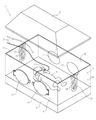
保育器1は、図1および図2に示すように、平面的に見てほぼ長方形状などの基台2と、この基台2のほぼ外周囲に沿って立設されているほぼ直方体形状などのフード3とを備えている。また、基台2上には、臥床架(図示せず)が配置され、この臥床架上には、未熟児などの児4が収容されて保育される。そして、フード3は、全体としてほぼ透明であってよく、前側の壁部5、後側の壁部6、頭側の壁部7および脚側の壁部8をそれぞれ備えている。また、前側の壁部5は、処置窓を構成しているので、その下端部を支点として外側に向かって往回動し得るように構成されている。さらに、前側の壁部5および後側の壁部6には、左右一対などの手入れ窓11が配置されていてよい。
1. Schematic description of the entire incubator As shown in FIG. 1 and FIG. 2, the incubator 1 includes a
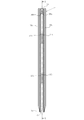
フード3は、図1および図2に示すように、天面フード12をさらに備えている。また、この天面フード12は、伸縮可能な支柱、駆動用チェーン、電動モータなどの駆動機構(何れも図示せず)によって、上下方向に往復駆動されるように構成されている。そして、天面フード12が図1に示すように下降位置まで移動したときには、保育器1は、閉鎖型保育器として機能する。また、天面フード12が図2に示すように上昇位置まで移動したときには、保育器1は、開放型保育器として機能する。さらに、フード3の頭側の壁部7、脚側の壁部8などには、グロメット部材13がそれぞれ取り付けられている。そして、図示の実施例においては、人工呼吸器を用いて児4に酸素を供給するための酸素マスク4の酸素供給用チューブ15がフード3の外部からグロメット部材13のケーブル類保持用の切れ目16を通してフード3の内部に導き入れられている。したがって、この酸素供給用チューブ15は、吸気用、呼気用などの複数本のチューブが束ねられた状態でもって蛇腹状の外被チューブによって被覆されたものであってよい。
As shown in FIGS. 1 and 2, the
なお、グロメット部材13およびその取り付け構造については、次項(すなわち、「2、グロメット構造の説明」の項)において詳細に説明するので、グロメット部材13およびその取り付け機構についての詳細な説明は、この項では省略する。さらに、グロメット部材13およびその取り付け機構以外の保育器1の構成は周知のものであってよく、また、グロメット部材13およびその取り付け構造以外の保育器1の構成の詳細は本発明の要旨ではないので、その詳細な図示および詳細な説明は、本文においては省略する。
The
2、グロメット構造の説明
図1および図2に示す保育器1のフード3(具体的には、頭側の壁部7および脚側の壁部8)に取り付けられているグロメット構造21は、図3〜図9に示すように、グロメット部材13と、このグロメット部材13を保育器1のフード3に取り付けるために、このフード13に設けられたグロメット取り付け部22とを備えている。そして、グロメット部材13は、図3に示すように、シリコーンゴムなどの合成ゴム、天然ゴム、シリコーン樹脂、ビニル樹脂などの合成樹脂などの比較的軟質の弾性材料から一体成形されることによって、正面から見て上下方向に細長くかつ中実であるほぼU字形状に構成されていてよい。
2. Description of Grommet Structure The
グロメット部材13は、図3に示すように、つぎの(a)項〜(d)項に記載の部分を備えている。
(a)正面から見てグロメット部材13の外周囲に沿って上下方向に細長いほぼU字形状に構成されている被取り付け部23、
(b)この被取り付け部23の左右一対の上端部の間をほぼ延在している上縁部24、
(c)正面から見て上記グロメット部材13のほぼ中央部分を上縁部24から被取り付け部23のほぼ半円形状の下縁部25付近まで延在しているケーブル類支持部26、および
(d)被取り付け部23とケーブル類支持部26とを連結するために、両者の間隙を面状態で埋めるように両者の間に延在している連結部(換言すれば、面状連結部)27。
As shown in FIG. 3, the
(A) A mounted
(B) an
(C) a
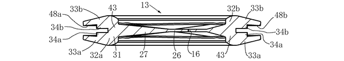
グロメット部材13の被取り付け部23は、図6〜図8に示すように、断面がほぼU字状(換言すれば、ほぼコ字状)の被取り付け部本体31を備えている。そして、この被取り付け部本体31は、被取り付け部23の外周囲のほぼ全体に沿って延在しているので、正面から見て上下方向に細長いほぼU字形状に構成され、このために、図3に示すように、左右一対の腕部32a、32bを備えている。また、被取り付け部本体31の左右一対の腕部32a、32bの前後一対の長板形状部33a、33bの中間部分の内側には、前後一対の上側係止部34a、34bおよび前後一対の下側係止係部35a、35bがそれぞれ形成されている。そして、長板形状部33a、33bの上端部付近の内側にも、前後一対の係止部36a、36bがそれぞれ形成されている。なお、図示の実施例においては、係止部34a、34b、35a、35bは、図3、図4、図7および図8に示すように、長板形状部33a、33bから外方に向かって斜め上方に突出した状態でもって、これらの長板形状部33a、33bと一体に形成されている。また、係止部36a、36bは、長板形状部33a、33bの上端部の下面からほぼ下方に向かって突出した状態でもって、上端部と一体に形成されている。
As shown in FIGS. 6 to 8, the attached
グロメット部材13の上縁部24の左右方向におけるほぼ中央部分には、切れ目37が形成されている。また、ケーブル類支持部26にも、上端部から下端部付近までほぼ蛇行しながら上下方向に延在している切れ目38が形成されている。そして、これらの切れ目37および切れ目38によって、グロメット部材13のケーブル類保持用の切れ目16が構成されている。また、切れ目38の下端部には、ほぼ水平方向に延在している切れ目39も、この切れ目38に対してほぼ逆T字状になるようにほぼ直交した状態で連なって形成されている。さらに、切れ目38(換言すれば、ケーブル類保持用の切れ目16)は、図3に示すように、ほぼ波形の形状(換言すれば、複数個の(換言すれば、1個よりも多い)ほぼS字の形状をつなぎ合わせた形状または1個のほぼS字の形状、さらに換言すれば、複数個の(換言すれば、1個よりも多い)ほぼサインカーブの形状をつなぎ合わせた形状または1個のほぼサインカーブの形状)であってよい。この場合、ほぼS字の形状およびほぼサインカーブの形状のそれぞれは、左右方向(換言すれば、切れ目38の長さ方向に延在している中心線Lとは直交する方向)において偏平になるように構成されているのが好ましい。また、切れ目16、38は、中心線Lから左側または右側にそれぞれ突出している2個以上のほぼ円弧状の突出部分をつなぎ合わせた連続曲線であるのが好ましい。
A
切れ目38(換言すれば、ケーブル類保持用の切れ目16)は、図示の実施例においては、これらの切れ目16、38の長さ方向に延在している中心線Lの左右両側を合わせて、図3に示すように約4.5個のほぼ円弧状の突出部分41a、41b、41c、41d、41eを有している。ただし、円弧状突出部分41eは、残りの円弧状突出部分41a〜41dの約半分である。そして、切れ目16、38がそれぞれ有する円弧状突出部分41a〜41eの個数は、実用性の観点から見て一般的に、2〜9個の範囲であるのが好ましく、3〜7個の範囲であるのがさらに好ましい。また、各円弧状部分41a〜41dは、図示の実施例においては、切れ目16、38の長さ方向における長さ(換言すれば、円弧状突出部分41a〜41eの幅)Wに対する切れ目16、38における幅方向の長さ(換言すれば、円弧状突出部分41a〜41eの高さ)Hの比(すなわち、H/W)が約0.25である。そして、この比H/Wは、実用性の観点から見て一般的に、0.15〜0.6の範囲であるのが好ましく、0.2〜0.4の範囲であるのがさらに好ましい。また、上記幅Wは、図示の実施例においては、約3.3cmである。そして、この幅Wは、実用性の観点から見て一般的に、1.5〜8cmの範囲であるのが好ましく、2.5〜6cmの範囲であるのがさらに好ましい。また、上記高さHは、図示の実施例においては、約8mmである。そして、この高さHは、実用性の観点から見て一般的に、3.5〜20mmの範囲であるのが好ましく、6〜15mmの範囲であるのがさらに好ましい。
In the illustrated embodiment, the cut line 38 (in other words, the
グロメット部材13のケーブル類保持部27は、図3に示すように、切れ目38の左右両側に沿って延在している左右一対の保持片部42a、42bを有している。そして、これら左右一対の保持片部42a、42bは、切れ目38の下端部において連絡部43によって切れ目39を部分的に介してつながっている。したがって、左右一対の保持片部42a、42bも、切れ目38とほぼ同様に、上方から下方に向かってほぼ蛇行しながらほぼ帯状に(換言すれば、ほぼ等幅で)延在している。なお、左右一対の保持片部42a、42bのそれぞれの幅は、図示の実施例においては、約9mmである。そして、この幅は、実用性の観点から見て一般的に、3〜18mmの範囲であるのが好ましく、5〜15mmの範囲であるのがさらに好ましい。また、左右一対の保持片部42a、42bのそれぞれは、図7および図8に示すように、図示の実施例においては、全体的にほぼ等厚に構成されていて、これらのそれぞれの厚みは、約1.2mmである。そして、これらのそれぞれの厚みは、実用性の観点から見て一般的に、0.6〜2.5mmの範囲であるのが好ましく、0.9〜1.8mmの範囲であるのがさらに好ましい。
As shown in FIG. 3, the
グロメット部材13の被取り付け部23の取り付け部本体31は、図7および図8に示すように、一対の長板形状部33a、33bを連結している基板部43を有している。そして、この基板部43の厚みは、保持片部42a、42bの厚みに較べて十分に厚く構成されている。また、面状連結部27は、基板部43(換言すれば、取り付け部本体31、さらに換言すれば、被取り付け部23)から保持片部42a、42bにかけて、その厚みが次第に小さくなるように構成され、保持片部42a、42bの近傍では、保持片部42a、42bとほぼ等厚になっている。また、グロメット部材13の上縁部24も、図5に示すように、その両端部から切れ目37にかけて、その厚みが次第に小さくなるように構成され、切れ目37の近傍では、保持片部42a、42bのそれぞれとほぼ等厚になっている。
As shown in FIGS. 7 and 8, the attachment portion
フード3(図示の実施例においては、頭側の壁部7および脚側の壁部8)には、図1および図6に示すように、グロメット取り付け部22を構成するための開口(換言すれば、グロメット取り付け用開口)44が形成されている。そして、これらの開口44は、壁部7、8の上端部(換言すれば、端部)において外部に連通している切り込み形状に構成されている。なお、以下においては、脚側の壁部8に取り付けられているグロメット部材13の取り付け構造について図1、図2および図6を参照しつつ説明するが、頭側の壁部7に取り付けられているグロメット部材13およびその取り付け構造も、脚側壁部8のものと実質的に同一であってよい。
As shown in FIGS. 1 and 6, the hood 3 (in the illustrated embodiment, the head-
グロメット取り付け用開口44は、基本的には、図6に示すように、グロメット部材13の被取り付け部23の連結部43の外周囲にほぼ沿った形状を有している。ただし、この開口44は、被取り付け部23の左右一対の腕部32a、32bの上端部付近(係止部36a、36bを含む。)、上側係止部34a、34bおよび下側係止部35a、35bにそれぞれ隣接する部分では、切り込み形状の小開口45a、45b、46a、46b、47a、47bをそれぞれ有している。そして、これらの小開口45a、45b、46a、46b、47a、47bは、開口44の一部を構成するように、開口44に連通している。
As shown in FIG. 6, the grommet attachment opening 44 basically has a shape substantially along the outer periphery of the connecting
グロメット部材13を脚側の壁部8のグロメット取り付け部22に取り付けるときには、グロメット部材13をその下端部からグロメット取り付け用開口44に挿入してこの開口44に嵌め込む。この場合、脚側壁部8のうちの、開口44の周囲に沿った部分が、グロメット部材13の被取り付け部23の左右両側の腕部32a、32bの外周溝48a、48bおよび下縁部25の外周溝49(図4および図7参照)にそれぞれ嵌め込まれる。また、グロメット部材13の上記挿入の際には、下側の係止部35a、35bおよび上側の係止部34a、34bは、前後方向に互いに間隔を広げながら脚側壁部8のうちの開口44の周囲に沿った部分を下方に摺動して、小開口47a、47b、46a、46bにそれぞれ嵌め込まれる。そして、被取り付け部23の左右一対の腕部32a、32bの上端部および係止部36a、36bは、小開口45a、45bにそれぞれ嵌め込まれて、図2および図6に示すように、上縁部24の上面が脚側壁部8の上面とほぼ面一になる。
When the
上述の取り付け操作によって、図2および図6に示すように、グロメット部材13をフード3に取り付けることができるので、この取り付け状態(換言すれば、保育器1が図2に示すように開放型保育器として機能している状態)においては、ケーブル類15をフード3の外側上方からグロメット部材13の切れ目16を通してフード3の内部に導き入れることができる。具体的には、ケーブル類15の適当箇所を上縁部24の切れ目37に上方から当てがって切れ目37に押し込むように下方に移動させると、ケーブル類15は、この切れ目37からケーブル類保持部26の切れ目38に導入される。そして、このケーブル類15は、比較的弾性の大きい一対の保持片部42a、42bによって、適当位置に弾性的に保持される。また、一対の保持片部42a、42bの切れ目37側には、互いに嵌り合うように構成されたほぼ円弧状の凹部およびほぼ円弧状の凸部が設けられている。このために、ケーブル類15は、一対の保持片部42a、42bによって、程よい弾性力でもって支持されるので、上方または下方に不測に移動したり、このケーブル類の長さ方向に不測に移動したりするおそれがなく、したがって、ケーブル類15が一対の保持片部42a、42bとの度重なる摺動摩擦によって損傷するおそれがない。さらに、一対の保持片部42a、42bが薄くてその弾性が大きいので、ケーブル類15が切れ目37に挿入されている状態でも、保育器1が図1に示すように閉鎖型保育器として機能しているときに、フード3の内部と外部とを連通する隙間(換言すれば、ケーブル類15の上記挿入によって一対の保持片部42a、42bの間に形成される隙間)をできるだけ小さくすることができる。このために、保育器1が、閉鎖型保育器として機能しているときに、フード3の内部に上記隙間を通して導入される外気をできるだけ少なくすることができる。
As shown in FIGS. 2 and 6, the
上述のとおりであるから、図示の実施例に示すグロメット構造21は、開放型保育器兼用の閉鎖型保育器1に適用するのに特に好適である。具体的には、ケーブル類15は、保育器1が開放型保育器として機能しているときに、ケーブル類保持部26に上述のようにきわめて簡単な操作でもって保持されることができる。それでいて、保育器1が閉鎖型保育器として機能しているときには、上述のように、フード3の内部への外気の導入をできるだけ少なくすることがきる。なお、酸素マスク14などの比較的大きな器具類がケーブル類15の先端部側に取り付けられていないときには、ケーブル類15の先端部をフード3の外側から切れ目38に差し込むことによって、ケーブル類15を一対の保持片部42a、42bの間に保持させることも可能である。
Since it is as above-mentioned, the
以上において、本発明の一実施例について詳細に説明したが、本発明は、この実施例に限定されるものではなく、特許請求の範囲に記載された発明の趣旨に基づいて各種の変更および修正を施されることが可能である。 Although one embodiment of the present invention has been described in detail above, the present invention is not limited to this embodiment, and various changes and modifications can be made based on the spirit of the invention described in the claims. Can be applied.
例えば、上述の実施例においては、グロメット部材13をフード3の取り付け部22に中心線Lがほぼ垂直になるように取り付けた。しかし、この取り付けは、中心線Lがフード3に対して傾斜した状態またはほぼ水平な状態で取り付けることができ、このように傾斜した状態で取り付ける場合には、グロメット部材13の上縁部24が中心線Lに対してほぼ直交している必要は必ずしもなく、傾斜していてもよい。
For example, in the above-described embodiment, the
また、上述の実施例においては、フード3のグロメット取り付け部22のグロメット取り付け用開口44を切り込み形状にして、グロメット部材13の上縁部24(換言すれば、切れ目16)および左右一対の腕部32a、32bの上端部が外部に露出するようにした。しかし、切れ目16が外部に露出している必要は必ずしもないので、グロメット取り付け用開口44は閉ループ形状であってもよく、この場合、比較的大きな器具類14は取り付けられていないケーブル類15の先端部または基端部をフード3の外側または内側から切れ目16に差し込むことによって、ケーブル類15を一対の保持片部42a、42bの間に保持させることができる。
Further, in the above-described embodiment, the
さらに、上述の実施例においては、開放型保育器兼用の閉鎖型保育器に本発明を適用したが、本発明は、開放型保育器にも適用することができる。また、本発明は、場合によっては、閉鎖型保育器や搬送用保育器などにも適用することができ、この場合には、天面フード12のうちの、グロメット構造21にほぼ対応する部分などを、上方などに開放可能なグロメット挿入用の開閉蓋によって構成することもできる。
Furthermore, in the above-described embodiment, the present invention is applied to a closed type incubator that also serves as an open type incubator, but the present invention can also be applied to an open type incubator. In addition, the present invention can be applied to a closed type incubator or a transport incubator depending on circumstances, and in this case, a portion of the
1 開放型保育器兼用の閉鎖型保育器(保育器)
3 フード
13 グロメット部材
15 酸素供給用チューブ(ケーブル類、長手状部材)
16 ケーブル類保持用切れ目(長手状部材保持用切れ目)
21 グロメット構造
22 グロメット取り付け部
23 被取り付け部
27 面状連結部(連結部)
42a 保持片部
42b 保持片部
1 Open type incubator closed type incubator (Incubator)
3
16 Cuts for holding cables (cuts for holding long members)
21
Claims (6)
上記グロメット部材が長手状部材を貫通させた状態で保持するための長手状部材保持用の切れ目を有する、保育器におけるグロメット構造において、
上記長手状部材保持用切れ目が、少なくとも1個のほぼS字の形状に蛇行した形状に構成されていることを特徴とするグロメット構造。 A grommet attaching portion provided on the hood of the incubator, and a grommet member attached to the grommet attaching portion;
In the grommet structure in the incubator, the grommet member has a slit for holding the longitudinal member for holding the longitudinal member in a state of passing through the longitudinal member.
The grommet structure characterized in that the longitudinal member holding cut is formed in a shape meandering into at least one substantially S-shape.
上記グロメット部材が長手状部材を貫通させた状態で保持するための長手状部材保持用の切れ目を有する、保育器におけるグロメット構造において、
上記長手状部材保持用切れ目が、少なくとも1個のほぼサインカーブの形状に蛇行した形状に構成されていることを特徴とするグロメット構造。 A grommet attaching portion provided on the hood of the incubator, and a grommet member attached to the grommet attaching portion;
In the grommet structure in the incubator, the grommet member has a slit for holding the longitudinal member for holding the longitudinal member in a state of passing through the longitudinal member.
A grommet structure in which the slit for holding a longitudinal member is configured to meander in at least one substantially sinusoidal shape.
上記グロメット部材が長手状部材を貫通させた状態で保持するための長手状部材保持用の切れ目を有する、保育器におけるグロメット構造において、
上記長手状部材保持用切れ目が、ほぼ波形の形状に構成されていることを特徴とするグロメット構造。 A grommet attaching portion provided on the hood of the incubator, and a grommet member attached to the grommet attaching portion;
In the grommet structure in the incubator, the grommet member has a slit for holding the longitudinal member for holding the longitudinal member in a state of passing through the longitudinal member.
The grommet structure, wherein the slit for holding the long member is formed in a substantially wave shape.
上記連結部の厚みが、上記被取り付け部から上記一対の保持片部のそれぞれにかけて、次第にほぼ小さくなるように構成されていることを特徴とする請求項1、2または3に記載のグロメット構造。 The grommet member is provided on the grommet member substantially along the outer periphery of the grommet member and has a thick attachment portion attached to the grommet attachment portion, and the longitudinal member holding cut line. A pair of holding pieces having a small thickness formed on both sides of the slit for holding the longitudinal member, and a connecting part that connects the attached part and the pair of holding pieces in a surface state,
4. The grommet structure according to claim 1, wherein a thickness of the connecting portion is configured to gradually become substantially smaller from the attached portion to each of the pair of holding piece portions.
上記一対の保持片部のそれぞれの厚みが0.6〜2.5mmの範囲であることを特徴とする請求項4に記載のグロメット構造。 The width of each of the pair of holding pieces is in the range of 3 to 18 mm,
The grommet structure according to claim 4, wherein each of the pair of holding piece portions has a thickness in a range of 0.6 to 2.5 mm.
上記一対の保持片部のそれぞれの厚みが0.9〜1.8mmの範囲であることを特徴とする請求項4に記載のグロメット構造。 The width of each of the pair of holding pieces is in the range of 5 to 15 mm,
5. The grommet structure according to claim 4, wherein the thickness of each of the pair of holding pieces is in a range of 0.9 to 1.8 mm.
Priority Applications (4)
| Application Number | Priority Date | Filing Date | Title |
|---|---|---|---|
| JP2008174209A JP5123082B2 (en) | 2008-07-03 | 2008-07-03 | Grommet structure in incubator |
| EP09005969A EP2140848B1 (en) | 2008-07-03 | 2009-04-30 | Grommet structure in incubator |
| US12/465,398 US8337384B2 (en) | 2008-07-03 | 2009-05-13 | Grommet structure in incubator |
| CN200910141764.1A CN101617982B (en) | 2008-07-03 | 2009-05-25 | Grommet structure in incubator |
Applications Claiming Priority (1)
| Application Number | Priority Date | Filing Date | Title |
|---|---|---|---|
| JP2008174209A JP5123082B2 (en) | 2008-07-03 | 2008-07-03 | Grommet structure in incubator |
Publications (2)
| Publication Number | Publication Date |
|---|---|
| JP2010012003A true JP2010012003A (en) | 2010-01-21 |
| JP5123082B2 JP5123082B2 (en) | 2013-01-16 |
Family
ID=41170179
Family Applications (1)
| Application Number | Title | Priority Date | Filing Date |
|---|---|---|---|
| JP2008174209A Active JP5123082B2 (en) | 2008-07-03 | 2008-07-03 | Grommet structure in incubator |
Country Status (4)
| Country | Link |
|---|---|
| US (1) | US8337384B2 (en) |
| EP (1) | EP2140848B1 (en) |
| JP (1) | JP5123082B2 (en) |
| CN (1) | CN101617982B (en) |
Cited By (2)
| Publication number | Priority date | Publication date | Assignee | Title |
|---|---|---|---|---|
| JP2014018223A (en) * | 2012-07-12 | 2014-02-03 | Atom Medical Corp | Infant incubator and method of application thereof |
| JP2014033769A (en) * | 2012-08-08 | 2014-02-24 | Atom Medical Corp | Recumbent bed for infant incubator and infant incubator with recumbent bed, and method for using recumbent bed for infant incubator |
Families Citing this family (20)
| Publication number | Priority date | Publication date | Assignee | Title |
|---|---|---|---|---|
| US10076266B2 (en) | 2010-07-07 | 2018-09-18 | Aspect Imaging Ltd. | Devices and methods for a neonate incubator, capsule and cart |
| IL226488A (en) | 2013-05-21 | 2016-07-31 | Aspect Imaging Ltd | Cradle for neonates |
| US11278461B2 (en) | 2010-07-07 | 2022-03-22 | Aspect Imaging Ltd. | Devices and methods for a neonate incubator, capsule and cart |
| US10499830B2 (en) | 2010-07-07 | 2019-12-10 | Aspect Imaging Ltd. | Premature neonate life support environmental chamber for use in MRI/NMR devices |
| CN101947170B (en) * | 2010-09-10 | 2012-06-20 | 深圳市宝安区妇幼保健院 | Infant incubator and infant head fixing device |
| DE202011051313U1 (en) * | 2010-09-16 | 2011-11-23 | Aspect Magnet Technologies Ltd. | Closed life support system for premature babies |
| US10794975B2 (en) | 2010-09-16 | 2020-10-06 | Aspect Imaging Ltd. | RF shielding channel in MRI-incubator's closure assembly |
| US8716602B2 (en) | 2010-11-01 | 2014-05-06 | Eaton Corporation | Cable grommet for use with a raised floor |
| CN102309803A (en) * | 2011-09-15 | 2012-01-11 | 吴江富凯医用卫生用品有限公司 | Plastic shell of oxygen supply device for infant and young child |
| CN102551978B (en) * | 2012-01-19 | 2015-03-25 | 美时医疗技术(上海)有限公司 | Infant incubator compatible with magnetic resonance |
| DE102012212572B4 (en) * | 2012-07-18 | 2018-02-08 | Drägerwerk AG & Co. KGaA | Thermotherapy device |
| CN105722488A (en) | 2013-09-02 | 2016-06-29 | 阿斯派克影像有限公司 | Passive thermo-regulated neonatal transport incubator |
| DE202013104934U1 (en) | 2013-11-03 | 2013-11-20 | Aspect Imaging Ltd. | Patiententransportinkubator |
| US10383782B2 (en) | 2014-02-17 | 2019-08-20 | Aspect Imaging Ltd. | Incubator deployable multi-functional panel |
| JP6181137B2 (en) * | 2015-11-16 | 2017-08-16 | アトムメディカル株式会社 | Incubator |
| JP1559890S (en) * | 2016-01-19 | 2016-10-03 | ||
| USD814719S1 (en) * | 2016-07-21 | 2018-04-03 | AUTO ELEX Co., LTD | Incubator for animal |
| US10224135B2 (en) | 2016-08-08 | 2019-03-05 | Aspect Imaging Ltd. | Device, system and method for obtaining a magnetic measurement with permanent magnets |
| US11287497B2 (en) | 2016-08-08 | 2022-03-29 | Aspect Imaging Ltd. | Device, system and method for obtaining a magnetic measurement with permanent magnets |
| US11052016B2 (en) | 2018-01-18 | 2021-07-06 | Aspect Imaging Ltd. | Devices, systems and methods for reducing motion artifacts during imaging of a neonate |
Citations (4)
| Publication number | Priority date | Publication date | Assignee | Title |
|---|---|---|---|---|
| JPS5039085U (en) * | 1973-08-02 | 1975-04-22 | ||
| JPH0924073A (en) * | 1995-07-13 | 1997-01-28 | Atom Medical Kk | Servicing window for medical treatment vessel |
| JP2002528142A (en) * | 1997-09-09 | 2002-09-03 | ヒル−ロム,インコーポレイティド | Hinged panel for warmer |
| JP2008126091A (en) * | 2006-11-16 | 2008-06-05 | Iseki & Co Ltd | Apparatus for sorting crop |
Family Cites Families (12)
| Publication number | Priority date | Publication date | Assignee | Title |
|---|---|---|---|---|
| US4885000A (en) | 1987-01-09 | 1989-12-05 | The Beth Israel Hospital Association | Isolation, sterilization and maximum observation tent |
| CN2150849Y (en) * | 1991-07-17 | 1993-12-29 | 徐企宏 | New born baby box |
| CN2185119Y (en) * | 1993-12-04 | 1994-12-14 | 东营市人民医院 | Electrothermic therapy bag with traditional Chinese medicine |
| US5954627A (en) | 1995-06-30 | 1999-09-21 | Atom Medical Corporation | Access port for use in medical vessel |
| JPH10248887A (en) | 1997-03-14 | 1998-09-22 | Atom Medical Kk | Access window for medical container |
| AU7354298A (en) * | 1997-04-25 | 1998-11-24 | Bo Nordell | Incubator arrangement for use in magnetic resonance imaging |
| US6022310A (en) | 1997-09-09 | 2000-02-08 | Hill-Rom, Inc. | Canopy adjustment mechanisms for thermal support apparatus |
| US6210320B1 (en) * | 1998-04-01 | 2001-04-03 | Small Beginnings, Inc. | Thermal and humidity barrier for extremely premature infants |
| US6336897B1 (en) * | 1999-12-11 | 2002-01-08 | Datex-Ohmeda, Inc. | Grommet for infant care apparatus |
| CN2554999Y (en) * | 2002-07-26 | 2003-06-11 | 巴特尔 | Operating node |
| US6867371B2 (en) * | 2003-04-23 | 2005-03-15 | Lucent Technologies Inc. | Fiber closure sealing apparatus |
| JP2006204496A (en) * | 2005-01-27 | 2006-08-10 | Atom Medical Corp | Incubator |
-
2008
- 2008-07-03 JP JP2008174209A patent/JP5123082B2/en active Active
-
2009
- 2009-04-30 EP EP09005969A patent/EP2140848B1/en active Active
- 2009-05-13 US US12/465,398 patent/US8337384B2/en active Active
- 2009-05-25 CN CN200910141764.1A patent/CN101617982B/en active Active
Patent Citations (4)
| Publication number | Priority date | Publication date | Assignee | Title |
|---|---|---|---|---|
| JPS5039085U (en) * | 1973-08-02 | 1975-04-22 | ||
| JPH0924073A (en) * | 1995-07-13 | 1997-01-28 | Atom Medical Kk | Servicing window for medical treatment vessel |
| JP2002528142A (en) * | 1997-09-09 | 2002-09-03 | ヒル−ロム,インコーポレイティド | Hinged panel for warmer |
| JP2008126091A (en) * | 2006-11-16 | 2008-06-05 | Iseki & Co Ltd | Apparatus for sorting crop |
Cited By (2)
| Publication number | Priority date | Publication date | Assignee | Title |
|---|---|---|---|---|
| JP2014018223A (en) * | 2012-07-12 | 2014-02-03 | Atom Medical Corp | Infant incubator and method of application thereof |
| JP2014033769A (en) * | 2012-08-08 | 2014-02-24 | Atom Medical Corp | Recumbent bed for infant incubator and infant incubator with recumbent bed, and method for using recumbent bed for infant incubator |
Also Published As
| Publication number | Publication date |
|---|---|
| US8337384B2 (en) | 2012-12-25 |
| JP5123082B2 (en) | 2013-01-16 |
| CN101617982A (en) | 2010-01-06 |
| EP2140848B1 (en) | 2012-12-19 |
| EP2140848A3 (en) | 2012-01-25 |
| CN101617982B (en) | 2014-05-07 |
| US20100004502A1 (en) | 2010-01-07 |
| EP2140848A2 (en) | 2010-01-06 |
Similar Documents
| Publication | Publication Date | Title |
|---|---|---|
| JP5123082B2 (en) | Grommet structure in incubator | |
| USD529651S1 (en) | Clip-on flexible reading light | |
| CN104743235B (en) | Slide rail structure | |
| JP5685509B2 (en) | child seat | |
| JP5399473B2 (en) | Curtain device carriage | |
| JP2016106707A (en) | Infant incubator | |
| JP6181137B2 (en) | Incubator | |
| KR20170026282A (en) | Assembly for carrying infants and toy bar thereof | |
| WO2015186008A1 (en) | Self-ligating bracket with passive or interactive clip | |
| JP2011518010A (en) | Multi-channel curtain groove, curtain device having at least one multi-channel curtain groove, and method for manufacturing multi-channel curtain groove | |
| JP5875960B2 (en) | Endoscope holding device and trolley | |
| US10206839B2 (en) | Incubator | |
| JP2014018223A (en) | Infant incubator and method of application thereof | |
| USD679000S1 (en) | Cushion for respiratory mask | |
| USD584353S1 (en) | Holder for writing or drawing instruments | |
| JP6117897B1 (en) | Incubator | |
| JP2015123175A (en) | Structure of side rail | |
| ATE539201T1 (en) | GABIONE WITH A CLOSED STRUCTURE | |
| KR200471993Y1 (en) | A pen with notebook | |
| JP2008050796A (en) | Window regulator | |
| JP3157031U (en) | Hook with adjustable height | |
| JP1735811S (en) | pen with cap | |
| ES2474092T3 (en) | Fixing bracket for an inflated balloon | |
| TWM460072U (en) | Wafer boat | |
| JPS61240912A (en) | Code receiver in desk |
Legal Events
| Date | Code | Title | Description |
|---|---|---|---|
| A621 | Written request for application examination |
Free format text: JAPANESE INTERMEDIATE CODE: A621 Effective date: 20110629 |
|
| A977 | Report on retrieval |
Free format text: JAPANESE INTERMEDIATE CODE: A971007 Effective date: 20121011 |
|
| TRDD | Decision of grant or rejection written | ||
| A01 | Written decision to grant a patent or to grant a registration (utility model) |
Free format text: JAPANESE INTERMEDIATE CODE: A01 Effective date: 20121016 |
|
| A01 | Written decision to grant a patent or to grant a registration (utility model) |
Free format text: JAPANESE INTERMEDIATE CODE: A01 |
|
| A61 | First payment of annual fees (during grant procedure) |
Free format text: JAPANESE INTERMEDIATE CODE: A61 Effective date: 20121025 |
|
| FPAY | Renewal fee payment (event date is renewal date of database) |
Free format text: PAYMENT UNTIL: 20151102 Year of fee payment: 3 |
|
| R150 | Certificate of patent or registration of utility model |
Free format text: JAPANESE INTERMEDIATE CODE: R150 Ref document number: 5123082 Country of ref document: JP Free format text: JAPANESE INTERMEDIATE CODE: R150 |
|
| R250 | Receipt of annual fees |
Free format text: JAPANESE INTERMEDIATE CODE: R250 |
|
| R250 | Receipt of annual fees |
Free format text: JAPANESE INTERMEDIATE CODE: R250 |
|
| R250 | Receipt of annual fees |
Free format text: JAPANESE INTERMEDIATE CODE: R250 |
|
| R250 | Receipt of annual fees |
Free format text: JAPANESE INTERMEDIATE CODE: R250 |
|
| R250 | Receipt of annual fees |
Free format text: JAPANESE INTERMEDIATE CODE: R250 |
|
| R250 | Receipt of annual fees |
Free format text: JAPANESE INTERMEDIATE CODE: R250 |
|
| R250 | Receipt of annual fees |
Free format text: JAPANESE INTERMEDIATE CODE: R250 |
|
| R250 | Receipt of annual fees |
Free format text: JAPANESE INTERMEDIATE CODE: R250 |
|
| R250 | Receipt of annual fees |
Free format text: JAPANESE INTERMEDIATE CODE: R250 |