EP2140848A2 - Grommet structure in incubator - Google Patents
Grommet structure in incubator Download PDFInfo
- Publication number
- EP2140848A2 EP2140848A2 EP09005969A EP09005969A EP2140848A2 EP 2140848 A2 EP2140848 A2 EP 2140848A2 EP 09005969 A EP09005969 A EP 09005969A EP 09005969 A EP09005969 A EP 09005969A EP 2140848 A2 EP2140848 A2 EP 2140848A2
- Authority
- EP
- European Patent Office
- Prior art keywords
- grommet
- incision
- attaching
- structure according
- incubator
- Prior art date
- Legal status (The legal status is an assumption and is not a legal conclusion. Google has not performed a legal analysis and makes no representation as to the accuracy of the status listed.)
- Granted
Links
Images


Classifications
-
- A—HUMAN NECESSITIES
- A61—MEDICAL OR VETERINARY SCIENCE; HYGIENE
- A61G—TRANSPORT, PERSONAL CONVEYANCES, OR ACCOMMODATION SPECIALLY ADAPTED FOR PATIENTS OR DISABLED PERSONS; OPERATING TABLES OR CHAIRS; CHAIRS FOR DENTISTRY; FUNERAL DEVICES
- A61G11/00—Baby-incubators; Couveuses
-
- A—HUMAN NECESSITIES
- A61—MEDICAL OR VETERINARY SCIENCE; HYGIENE
- A61G—TRANSPORT, PERSONAL CONVEYANCES, OR ACCOMMODATION SPECIALLY ADAPTED FOR PATIENTS OR DISABLED PERSONS; OPERATING TABLES OR CHAIRS; CHAIRS FOR DENTISTRY; FUNERAL DEVICES
- A61G11/00—Baby-incubators; Couveuses
- A61G11/009—Baby-incubators; Couveuses with hand insertion windows, e.g. in the walls
Definitions
- the present invention relates to a grommet structure in an incubator comprising a grommet attaching portion provided to an enclosure of the incubator and a grommet member attached to the grommet attaching portion, wherein the grommet member includes a longitudinal member holding incision to hold a longitudinal member that extends therethrough.
- a grommet structure in an incubator comprising a grommet attaching portion provided to an enclosure of the incubator and a grommet member attached to the grommet attaching portion, wherein the grommet member includes a longitudinal member holding incision to hold a longitudinal member such as an oxygen supply tube that extends therethrough, is conventionally known as disclosed in, e.g., International Publication WO 99/12512 (to be referred to as "the above prior patent reference” hereinafter).
- the grommet member employed the grommet structure disclosed in the above prior patent reference includes a comparatively thick substantially U-shaped attaching target member which is provided to the grommet member along the outer circumference (the entire outer circumference excluding the upper rim) of the grommet member.
- the substantially U-shaped attaching target member is attached to the grommet attaching portion of the enclosure of the incubator.
- a portion surrounded by the substantially U-shaped attaching target member is comparatively thin and constitutes a cable holder.
- the "cable” refers to various types of longitudinal members such as a tube, cable and electric cord for various types of instruments, e.g., an oxygen mask used in the incubator, or various types of such longitudinal members as a bundle obtained by bundling a plurality of longitudinal members having the same or different diameters (including a case in which a jacket tube such as a bellows tube covers the bundle of the plurality of longitudinal members).
- the cable holder of the grommet member of the above prior patent reference also has a cable holding incision formed of one vertical slit and a plurality of horizontal incisions.
- the vertical slit extends substantially vertically from the upper end of the holder to a region consisting of the lower end of the holder and its vicinity.
- the plurality of horizontal incisions extend substantially horizontally to be substantially perpendicular to the vertical incision.
- the cable holder cannot be very thin.
- the four holding pieces of the cable holder have comparatively low elasticity. Therefore, the cable tends to be damaged by repeated slide friction with the four holding pieces.
- the cable tends to move downward (or upward depending on the case) along the vertical incision or in the longitudinal direction of the cable.
- a large gap is formed among the four holding pieces. Then, a large amount of external air is introduced through the gap into the enclosure in the closed state.
- the present invention is to solve the drawbacks as described above of the grommet structure in the incubator of the above prior patent reference with a comparatively simple arrangement.
- an object of the present invention to provide a grommet structure in an incubator, in which a longitudinal member, held by a longitudinal member holding incision of a grommet member, that extends through the incision is less likely to move accidentally in the longitudinal direction of the incision or in the longitudinal direction of the longitudinal member.
- the present invention relates to a grommet structure in an incubator, comprising a grommet attaching portion provided to an enclosure of the incubator and a grommet member attached to the grommet attaching portion wherein the grommet member includes a longitudinal member holding incision to hold a longitudinal member such as an oxygen supply tube that extends therethrough, characterized in that the longitudinal member holding incision forms at least one type of meandrous shape selected from a group consisting of at least one substantially S-shaped shape, at least one substantially sine-curved shape and a substantially waving shape.
- the at least one type of meandrous shape may comprise at least one substantially S-shaped shape continuous curve, at least one substantially sine-curved shape continuous curve, or a substantially waving shape.
- the continuous curve is preferably compressed in a horizontal direction.
- the grommet member comprises a large-thickness attaching target portion provided to the grommet member to extend substantially along an outer circumference of the grommet member and attached to the grommet attaching portion, a pair of small-thickness holding pieces formed on two sides, respectively, of the longitudinal member holding incision substantially along the longitudinal member holding incision, and a planar connector which connects the attaching target portion to the pair of holding pieces in a planar manner, wherein a thickness of the planar connector decreases gradually from the attaching target portion toward the pair of holding pieces.
- the attaching target portion, the pair of holding pieces and the planar connector of the grommet member are integrally molded from an elastic material.
- each of the pair of holding pieces has a width falling within a range of 3 mm to 18 mm (preferably, 5 mm to 15 mm). Also, desirably, each of the pair of holding pieces has a thickness falling within a range of 0.6 mm to 2.5 mm (preferably, 0.9 mm to 1.8 mm).
- the incision includes a plurality of substantially arcuate projecting portions projecting to the left and right, and the number of projecting portions falls within a range of two to nine (preferably three to seven).
- each of the projecting portions has a width falling within a range of 1.5 cm to 8 cm (preferably 2.5 cm to 6 cm).
- each of the projecting portions also has a height falling within a range of 3.5 mm to 20 mm (preferably 6 mm to 15 mm).
- a ratio of the height to the width of each of the projecting portions falls within a range of 0.15 to 0.6 (preferably 0.2 to 0.4).
- the attaching target portion comprises an attaching target portion main body formed into a substantially U shape substantially along an outer circumference of the grommet member.
- the attaching target portion includes an outer circumferential groove, and a portion of the enclosure which extends along a grommet attaching opening engages with the outer circumferential groove.
- the attaching target portion includes a locking portion continuously provided to the attaching target portion main body, and a grommet attaching opening formed in the enclosure includes a notched small opening, the locking portion engaging with the small opening.
- a second incision extending substantially horizontally is formed in a lower end of the incision, and the incision and the second incision form a substantially inverted-T-shaped incision at a region consisting of the intersection of the two incisions and vicinities thereof.
- the grommet member is attached to the grommet attaching portion provided to at least a wall of one type selected from a group consisting of a front wall, a rear wall, an infant-head-side wall and an infant-leg-side wall that constitute the enclosure.
- the longitudinal member comprises a cable.
- the incubator comprises a closed type incubator serving also as an open type incubator.
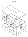
- an incubator 1 includes a base 2 which has a substantially rectangular shape or the like when seen from the top, and an enclosure 3 standing along substantially the outer circumference of the base 2 and having a substantially rectangular parallelepiped shape or the like.
- a mattress tray (not shown) is arranged on the base 2.
- An infant 4 such as an immature infant is accommodated and incubated on the mattress tray.
- the enclosure 3 can be substantially transparent as a whole, and includes a front wall (in other words, a side guard panel) 5, a rear wall (in other words, a side guard panel) 6, a wall 7 on the head side of the infant 4 (in other words, an end guard panel) and a wall 8 on the leg side of the infant 4 (in other words, an end guard panel).
- a front wall in other words, a side guard panel
- a rear wall in other words, a side guard panel 6
- a wall 7 on the head side of the infant 4 in other words, an end guard panel
- a wall 8 on the leg side of the infant 4 (in other words, an end guard panel).
- the front wall 5 constitutes a treatment window, it is pivotal forward toward outside about its lower end as a fulcrum.
- servicing windows 11 such as a pair of left and right servicing windows may be arranged in each of the front and rear walls 5 and 6.
- the enclosure 3 further includes a top hood 12, as shown in Figs. 1 and 2 .
- a driving mechanism such as a retractable support pillar, driving chain and electric motor or the like reciprocally drives the top hood 12 in the vertical direction.
- the incubator 1 serves as a closed type incubator.
- the incubator 1 serves as an open type incubator.
- a grommet member 13 is attached to each of the head-side wall 7 the leg-side wall 8 or the like of the enclosure 3.
- an oxygen supply cable 15 of an oxygen mask 14 to supply oxygen to the infant 4 using an artificial respirator is introduced into the enclosure 3 from outside the enclosure 3 through a cable holding incision 16 of the grommet member 13.
- the oxygen supply cable 15 may be a bundle of a plurality of tubes such as an inhaling tube and exhaling tube which is covered with a bellows jacket tube.
- each grommet member 13 and its attaching structure will be described in detail in the following item (namely, "2. Description on Grommet Member”) and the subsequent item (namely, “3. Description on Attaching Mechanism for Grommet Member”), respectively, and will be omitted in this item. Except for the grommet member 13 and its attaching mechanism, the arrangement of the incubator 1 can be a known one, and to describe it in detail is not the gist of the present invention. Hence, the arrangement of the incubator 1 will not be illustrated or described in detail in this DESCRIPTION.
- each grommet structure 21 attached to the enclosure 3 (more specifically, the head-side wall 7 and leg-side wall 8) of the incubator 1 shown in Figs. 1 and 2 includes the grommet member 13 and a grommet attaching portion 22.
- the grommet attaching portion 22 is provided to the enclosure 3 to attach the grommet member 13 to the enclosure 3 of the incubator 1.
- the grommet member 13 may be integrally molded using a comparatively soft elastic material such as synthetic rubber, e.g., silicone rubber, natural rubber, or a synthetic resin, e.g., a silicone resin or vinyl resin, into a substantially U shape when seen from the front, which is vertical band-like and solid.
- the grommet member 13 includes portions described in the following items (a) to (d):
- the attaching target portion 23 of the grommet member 13 includes an attaching target portion main body 31 having a substantially U-shaped section, as shown in Figs. 6 to 8 .
- the attaching target portion main body 31 extends substantially along the entire outer circumference of the attaching target portion 23, it forms a vertical band-like substantially U shape when seen from the front.
- the attaching target portion main body 31 includes a pair of left and right arms 32a and 32b, as shown in Fig. 3 .
- a pair of front and rear upper locking portions 34a and 34b and a pair of front and rear lower locking portions 35a and 35b are formed inside the intermediate portions of a pair of front and rear long plate-shaped portions 33a and 33b of the pair of left and right arms 32a and 32b of the attaching target portion main body 31. Also, a pair of front and rear locking portions 36a and 36b are formed inside regions consisting of the upper ends of the long plate-shaped portions 33a and 33b and their vicinities.
- the locking portions 34a and 34b, and 35a and 35b are formed integrally with the long plate-shaped portions 33a and 33b, respectively, to project outward from the long plate-shaped portions 33a and 33b, respectively, obliquely upward, as shown in Figs. 3 , 4 , 7 and 8 .
- the locking portions 36a and 36b are formed integrally with the upper ends of the long plate-shaped portions 33a and 33b such that the locking portions 36a and 36b project substantially downward from the lower surfaces of the upper ends of the long plate-shaped portions 33a and 33b.
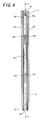
- An incision 37 is formed at substantially the central portion in the horizontal direction of the upper rim 24 of the grommet member 13.
- An incision 38 is formed in the cable support 26 and extends vertically while substantially winding from the upper end to a region consisting of the lower end of the cable support 26 and its vicinity.
- the incisions 37 and 38 constitute the cable holding incision 16 of the grommet member 13.
- An incision 39 extending substantially in the horizontal direction is formed at the lower end of the incision 38 to be continuous to it, so that it is substantially perpendicular to the incision 38, thus forming a substantially-inverted-T shape.
- the incision 38 (in other words, the cable holding incision 16) can have a substantially waving shape, as shown in Fig. 3 .
- the incision 16 can have a shape obtained by connecting a plurality (in other words, two or more) of substantially S shapes, or one substantially S shape.
- the incision 16 can have a shape obtained by connecting a plurality (in other words, two or more) of substantially sine-curved shapes, or one substantially sine-curved shape.
- each of the substantially S shape and the substantially sine-curved shape is preferably compressed in the horizontal direction (in other words, in a direction perpendicular to a center line L extending in the longitudinal direction of the incision 16).
- the incision 16 preferably forms a continuous curve obtained by connecting two or more substantially arcuate projecting portions extending from the center line L to the left and right.
- the cable holding incision 16 has about 4.5 pieces of substantially arcuate projecting portions 41a, 41b, 41c, 41d and 41e, as shown in Fig. 3 , on the left and right sides of the center line L extending in the longitudinal direction of the incision 16.
- the size of the arcuate projecting portion 41e is substantially half that of each of the remaining arcuate projecting portions 41a to 41d.
- the number of arcuate projecting portions 41a to 41e of the incision 16 preferably falls within a range of two to nine from the viewpoint of practicality, and desirably a range of three to seven.
- the length of each of the arcuate projecting portions 41a to 41d in the longitudinal direction of the incision 16 is defined as W and that the length of each of the arcuate projecting portions 41a to 41d in the widthwise direction of the incision 16 (in other words, the height of each of the arcuate projecting portions 41a to 41e) is defined as H.
- the ratio of the height H to the width W is about 0.25 in the embodiment shown in the drawings.
- the ratio H/W preferably falls within a range of 0.15 to 0.6 from the viewpoint of practicality, and desirably a range of 0.2 to 0.4.
- the width W is about 3.3 cm in the embodiment shown in the drawings. Generally, the width W preferably falls within a range of 1.5 cm to 8 cm from the viewpoint of practicality, and desirably a range of 2.5 cm to 6 cm.
- the height H is about 8 mm in the embodiment shown in the drawings. Generally, the height H preferably falls within a range of 3.5 mm to 20 mm from the viewpoint of practicality, and desirably a range of 6 mm to 15 mm.
- the cable support 26 of the grommet member 13 has a pair of left and right holding pieces 42a and 42b extending on the left and right sides, respectively, of the incision 38.
- a link 40 at the lower end of the incision 38 connects the pair of left and right holding pieces 42a and 42b partially via the incision 39.
- the pair of left and right holding pieces 42a and 42b also extend to substantially form a band (in other words, with substantially the same width) while substantially winding downward from above.
- each of the pair of left and right holding pieces 42a and 42b has a width of about 9 mm.
- this width preferably falls within a range of 3 mm to 18 mm from the viewpoint of practicality, and desirably a range of 5 mm to 15 mm.
- each of the pair of left and right holding pieces 42a and 42b has a substantially equal overall thickness, as shown in Figs. 7 and 8 , and its thickness is about 1.2 mm.
- this thickness preferably falls within a range of 0.6 mm to 2.5 mm from the viewpoint of practicality, and desirably a range of 0.9 mm to 1.8 mm.
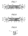
- the attaching target portion main body 31 of the attaching target portion 23 of the grommet member 13 has a base plate portion 43 which connects the pair of long plate-shaped portions 33a and 33b, as shown in Figs. 7 and 8 .
- the base plate portion 43 is sufficiently thicker than each of the holding pieces 42a and 42b.
- the thickness of the planar connector 27 gradually decreases from the base plate portion 43 (in other words, the attaching target portion main body 31 and furthermore the attaching target portion 23) toward the holding pieces 42a and 42b and, near the holding pieces 42a and 42b, is substantially equal to that of each of the holding pieces 42a and 42b.
- the thickness of the upper rim 24 of the grommet member 13 also gradually decreases from its two ends toward the incision 37, as shown in Fig. 5 and, in a region consisting of the incision 37 and its vicinity, is substantially equal to that of each of the holding pieces 42a and 42b.
- the enclosure 3 (in the embodiment shown in the drawings, the head-side wall 7 and leg-side wall 8) has openings (in other words, grommet attaching openings) 44 to constitute the grommet attaching portions 22, as shown in Figs. 1 and 6 .
- the openings 44 form notches communicating with the outside at the upper ends (in other words, the ends) of the walls 7 and 8, respectively.
- the attaching structure for the grommet member 13 attached to the leg-side wall 8 will be described with reference to Figs. 1 , 2 and 6 .
- the grommet member 13 attached to the head-side wall 7, and its attaching structure can be substantially the same as those of the leg-side wall 8.
- the grommet opening 44 has a shape substantially conforming to the outer circumference of the link 40 of the attaching target portion 23 of the grommet member 13, as shown in Fig. 6 .
- the opening 44 has notched small openings 45a and 45b, 46a and 46b and 47a and 47b at portions adjacent to regions consisting of the upper end portions of the pair of left and right arms 32a and 32b of the attaching target portion 23 and their vicinities (including the locking portions 36a and 36b), portions adjacent to the upper locking portions 34a and 34b and portions adjacent to the lower locking portions 35a and 35b, respectively.
- the small openings 45a, 45b, 46a, 46b, 47a and 47b communicate with the opening 44 to constitute part of the opening 44.
- the grommet member 13 When attaching the grommet member 13 to the grommet attaching portion 22 of the leg-side wall 8, the grommet member 13 is inserted from its lower end into the grommet attaching opening 44 and fitted in the opening 44.
- those portions of the leg-side wall 8 which extend along the circumference of the opening 44 are fitted in (in other words, engage with) outer circumferential grooves 48a and 48b of the left and right arms 32a and 32b and the outer circumferential groove 49 (see Figs. 4 and 7 ) of the lower rim 25, respectively, of the attaching target portion 23 of the grommet member 13.
- the upper ends of the pair of left and right arms 32a and 32b and the locking portions 36a and 36b of the attaching target portion 23 are fitted in (in other words, engage with) the small openings 45a and 45b, respectively, and the upper surface of the upper rim 24 becomes substantially flush with the upper surface of the leg-side wall 8, as shown in Figs. 2 and 6 .
- the grommet member 13 can be attached to the enclosure 3, as shown in Figs. 2 and 6 .
- the cable 15 can be introduced into the enclosure 3 from outside and above the enclosure 3 via the incision 16 of the grommet member 13. More specifically, when the operator abuts an appropriate portion of the cable 15 against the incision 37 of the upper rim 24 from above and moves it downward by pushing it into the incision 37, the cable 15 is introduced into the incision 38 of the cable support 26 through the incision 37. Then, the pair of comparatively highly elastic holding pieces 42a and 42b elastically hold the cable 15 at an appropriate position.
- the pair of holding pieces 42a and 42b on the incision 37 side (in other words, on a side above the cable 15) and a side opposite to it (in other words, on a side under the cable 15), are respectively provided with substantially arcuate recess and substantially arcuate projection (e.g., 41a and 41b) that engage with each other.
- the pair of holding pieces 42a and 42b hold the cable 15 with an appropriate elastic force, so that the cable 15 will not move upward or downward accidentally or in its longitudinal direction. Therefore, the cable 15 will not be damaged by repeated slide friction with the pair of holding pieces 42a and 42b.
- the pair of holding pieces 42a and 42b are thin and largely elastic.
- the gap through which the inside and outside of the enclosure 3 communicate with each other (in other words, the gap formed between the pair of holding pieces 42a and 42b when the cable 15 is inserted in the above manner) can be formed as small as possible.
- the incubator 1 serves as the closed type incubator, the external air introduced into the enclosure 3 through the gap can be minimized.
- the grommet structure 21 in the embodiment shown in the drawings is particularly suitable in the closed type incubator 1 serving also as an open type incubator. More specifically, when the incubator 1 serves as an open type incubator, the cable support 26 can hold the cable 15 with very simple manipulation as described above. On the other hand, when the incubator 1 serves as a closed type incubator, the amount of external air to be introduced into the enclosure 3 can be minimized, as described above. If a comparatively large instrument such as the oxygen mask 14 is not attached to the distal end of the cable 15, the cable 15 can be held between the pair of holding pieces 42a and 42b by inserting the distal end of the cable 15 into the incision 38 from outside the enclosure 3.
- the grommet member 13 is attached to the attaching portion 22 of the enclosure 3 such that the center line L is substantially vertical.
- the grommet member 13 can be attached such that the center line L is tilted with respect to the enclosure 3, or substantially horizontally.
- the upper rim 24 of the grommet member 13 need not be substantially perpendicular to the center line L, but may be tilted.
- the grommet attaching opening 44 of the grommet attaching portion 22 of the enclosure 3 has a notched shape, and the upper rim 24 (in other words, the incision 16) of the grommet member 13 and the upper ends of the pair of left and right arms 32a and 32b are exposed to the outside.
- the grommet attaching opening 44 may form a closed loop.
- the cable 15 can be held between the pair of holding pieces 42a and 42b by inserting the distal end or proximal end of the cable 15, to which no comparatively large instrument 14 is attached, into the incision 16 (in other words, the incision 38) from outside or inside the enclosure 3.
- the present invention is applied to a closed type incubator serving also as an open type incubator.
- the present invention can also be applied to an open type incubator.
- the present invention can also be applied to a closed type incubator, a transport incubator, and the like.
- that portion or the like of the top hood 12 which substantially corresponds to the grommet structure 21 may be formed of a grommet inserting openable/closeable lid that can be opened upward.
Abstract
Description
- The present invention relates to a grommet structure in an incubator comprising a grommet attaching portion provided to an enclosure of the incubator and a grommet member attached to the grommet attaching portion, wherein the grommet member includes a longitudinal member holding incision to hold a longitudinal member that extends therethrough.
- A grommet structure in an incubator comprising a grommet attaching portion provided to an enclosure of the incubator and a grommet member attached to the grommet attaching portion, wherein the grommet member includes a longitudinal member holding incision to hold a longitudinal member such as an oxygen supply tube that extends therethrough, is conventionally known as disclosed in, e.g., International Publication
WO 99/12512 - The cable holder of the grommet member of the above prior patent reference also has a cable holding incision formed of one vertical slit and a plurality of horizontal incisions. The vertical slit extends substantially vertically from the upper end of the holder to a region consisting of the lower end of the holder and its vicinity. The plurality of horizontal incisions extend substantially horizontally to be substantially perpendicular to the vertical incision. When the cable is to be held by the cable holder of the grommet member, the operator abuts an appropriate portion of the cable against the vertical incision from above and moves it downward by pushing it into the vertical incision. This introduces the cable into a substantially crisscross intersecting portion where the vertical incision and a horizontal incision intersect. Of the cable holder, four holding pieces that constitute the intersecting portion elastically position and hold the cable at a region consisting of the intersecting portion and its vicinity.
- In the case of the grommet structure in the incubator disclosed in the above prior patent reference, as the cable must be elastically held in position at the crisscross intersecting portion (in other words, the four holding pieces) of the cable holder of the grommet member, the cable holder cannot be very thin. As the cable holder of the grommet member cannot be very thin, the four holding pieces of the cable holder have comparatively low elasticity. Therefore, the cable tends to be damaged by repeated slide friction with the four holding pieces. As the four holding pieces cannot position and hold the cable reliably, the cable tends to move downward (or upward depending on the case) along the vertical incision or in the longitudinal direction of the cable. Furthermore, as the cable is inserted in the cable holding incision, a large gap is formed among the four holding pieces. Then, a large amount of external air is introduced through the gap into the enclosure in the closed state.
- The present invention is to solve the drawbacks as described above of the grommet structure in the incubator of the above prior patent reference with a comparatively simple arrangement.
- It is, therefore, an object of the present invention to provide a grommet structure in an incubator, in which a longitudinal member, held by a longitudinal member holding incision of a grommet member, that extends through the incision is less likely to move accidentally in the longitudinal direction of the incision or in the longitudinal direction of the longitudinal member.
- It is another object of the present invention to provide a grommet structure in an incubator, in which portions on the two sides of an incision can be comparatively thin, so that a gap through which the inside and outside of the enclosure communicate with each other can be small even when a longitudinal member extends through the incision.
- It is still another object of the present invention to provide a grommet structure in an incubator, in which a pair of holding pieces can reliably hold a longitudinal member from two sides with an appropriate elastic force, so that a gap through which the inside and outside of the enclosure communicate with each other can be smaller, and the longitudinal member is less likely to be damaged by repeated slide friction with the pair of holding pieces.
- It is yet another object of the present invention to provide a grommet structure in an incubator, in which a pair of holding pieces can be thin, so that a gap through which the inside and outside of the enclosure communicate with each other can be further smaller, and a longitudinal member can be less likely to be damaged by repeated slide friction with the pair of holding pieces.
- The present invention relates to a grommet structure in an incubator, comprising a grommet attaching portion provided to an enclosure of the incubator and a grommet member attached to the grommet attaching portion wherein the grommet member includes a longitudinal member holding incision to hold a longitudinal member such as an oxygen supply tube that extends therethrough, characterized in that the longitudinal member holding incision forms at least one type of meandrous shape selected from a group consisting of at least one substantially S-shaped shape, at least one substantially sine-curved shape and a substantially waving shape. In this case, the at least one type of meandrous shape may comprise at least one substantially S-shaped shape continuous curve, at least one substantially sine-curved shape continuous curve, or a substantially waving shape. When the at least one type of meandrous shape comprises a substantially S-shaped shape or substantially sine-curved shape, the continuous curve is preferably compressed in a horizontal direction.
- According to the first aspect to the present invention, the grommet member comprises a large-thickness attaching target portion provided to the grommet member to extend substantially along an outer circumference of the grommet member and attached to the grommet attaching portion, a pair of small-thickness holding pieces formed on two sides, respectively, of the longitudinal member holding incision substantially along the longitudinal member holding incision, and a planar connector which connects the attaching target portion to the pair of holding pieces in a planar manner, wherein a thickness of the planar connector decreases gradually from the attaching target portion toward the pair of holding pieces. According to the first aspect of the present invention, preferably, the attaching target portion, the pair of holding pieces and the planar connector of the grommet member are integrally molded from an elastic material. Preferably, each of the pair of holding pieces has a width falling within a range of 3 mm to 18 mm (preferably, 5 mm to 15 mm). Also, desirably, each of the pair of holding pieces has a thickness falling within a range of 0.6 mm to 2.5 mm (preferably, 0.9 mm to 1.8 mm).
- According to the second aspect of the present invention, the incision includes a plurality of substantially arcuate projecting portions projecting to the left and right, and the number of projecting portions falls within a range of two to nine (preferably three to seven). In this case, desirably, each of the projecting portions has a width falling within a range of 1.5 cm to 8 cm (preferably 2.5 cm to 6 cm). Also, desirably, each of the projecting portions also has a height falling within a range of 3.5 mm to 20 mm (preferably 6 mm to 15 mm). Furthermore, desirably, a ratio of the height to the width of each of the projecting portions falls within a range of 0.15 to 0.6 (preferably 0.2 to 0.4).
- According to the first and second aspects of the present invention, preferably, the attaching target portion comprises an attaching target portion main body formed into a substantially U shape substantially along an outer circumference of the grommet member. Also, preferably, the attaching target portion includes an outer circumferential groove, and a portion of the enclosure which extends along a grommet attaching opening engages with the outer circumferential groove. Furthermore, preferably, the attaching target portion includes a locking portion continuously provided to the attaching target portion main body, and a grommet attaching opening formed in the enclosure includes a notched small opening, the locking portion engaging with the small opening.
- According to the third aspect of the present invention, a second incision extending substantially horizontally is formed in a lower end of the incision, and the incision and the second incision form a substantially inverted-T-shaped incision at a region consisting of the intersection of the two incisions and vicinities thereof. According to the fourth aspect of the present invention, the grommet member is attached to the grommet attaching portion provided to at least a wall of one type selected from a group consisting of a front wall, a rear wall, an infant-head-side wall and an infant-leg-side wall that constitute the enclosure. According to the fifth aspect of the present invention, the longitudinal member comprises a cable. According to the sixth aspect of the present invention, the incubator comprises a closed type incubator serving also as an open type incubator.
- The above, and other, objects, features and advantages of the present invention will become readily apparent from the following detailed description thereof which is to be read in connection with the accompanying drawings.
-
-
Fig. 1 is a perspective view of an incubator in a closed state in an embodiment in which the present invention is applied to a closed type incubator serving as an open type incubator as well; -
Fig. 2 is a perspective view, similar toFig. 1 , of the incubator inFig. 1 in an open state; -
Fig. 3 is a front view, seen from outside the incubator, of a grommet member shown inFig. 1 ; -
Fig. 4 is a left side view of the grommet member inFig. 3 ; -
Fig. 5 is a plan view of the grommet member inFig. 3 ; -
Fig. 6 is a sectional view taken along the line A - A inFig. 4 ; -
Fig. 7 is a sectional view taken along the line B - B inFig. 3 ; -
Fig. 8 is a sectional view taken along the line C - C inFig. 3 ; and -
Fig. 9 is a sectional view taken along the line D - D inFig. 3 . - One embodiment in which the present invention is applied to a closed type incubator serving as an open type incubator as well will be described in "1. Schematic Description on Entire Incubator", "2. Description on Grommet Member" and "3. Description on Attaching Mechanism for Grommet Member" with reference to the accompanying drawings.
- As shown in
Figs. 1 and2 , anincubator 1 includes abase 2 which has a substantially rectangular shape or the like when seen from the top, and anenclosure 3 standing along substantially the outer circumference of thebase 2 and having a substantially rectangular parallelepiped shape or the like. A mattress tray (not shown) is arranged on thebase 2. Aninfant 4 such as an immature infant is accommodated and incubated on the mattress tray. Theenclosure 3 can be substantially transparent as a whole, and includes a front wall (in other words, a side guard panel) 5, a rear wall (in other words, a side guard panel) 6, awall 7 on the head side of the infant 4 (in other words, an end guard panel) and awall 8 on the leg side of the infant 4 (in other words, an end guard panel). As thefront wall 5 constitutes a treatment window, it is pivotal forward toward outside about its lower end as a fulcrum. Servicingwindows 11 such as a pair of left and right servicing windows may be arranged in each of the front andrear walls - The
enclosure 3 further includes atop hood 12, as shown inFigs. 1 and2 . A driving mechanism (neither is shown) such as a retractable support pillar, driving chain and electric motor or the like reciprocally drives thetop hood 12 in the vertical direction. When thetop hood 12 moves to the lower position, as shown inFig. 1 , theincubator 1 serves as a closed type incubator. When thetop hood 12 moves to the upper position, as shown inFig. 2 , theincubator 1 serves as an open type incubator. Agrommet member 13 is attached to each of the head-side wall 7 the leg-side wall 8 or the like of theenclosure 3. In the embodiment shown in the drawings, anoxygen supply cable 15 of anoxygen mask 14 to supply oxygen to theinfant 4 using an artificial respirator is introduced into theenclosure 3 from outside theenclosure 3 through acable holding incision 16 of thegrommet member 13. Hence, theoxygen supply cable 15 may be a bundle of a plurality of tubes such as an inhaling tube and exhaling tube which is covered with a bellows jacket tube. - Each
grommet member 13 and its attaching structure will be described in detail in the following item (namely, "2. Description on Grommet Member") and the subsequent item (namely, "3. Description on Attaching Mechanism for Grommet Member"), respectively, and will be omitted in this item. Except for thegrommet member 13 and its attaching mechanism, the arrangement of theincubator 1 can be a known one, and to describe it in detail is not the gist of the present invention. Hence, the arrangement of theincubator 1 will not be illustrated or described in detail in this DESCRIPTION. - As shown in
Figs. 3 to 9 , eachgrommet structure 21 attached to the enclosure 3 (more specifically, the head-side wall 7 and leg-side wall 8) of theincubator 1 shown inFigs. 1 and2 includes thegrommet member 13 and agrommet attaching portion 22. Thegrommet attaching portion 22 is provided to theenclosure 3 to attach thegrommet member 13 to theenclosure 3 of theincubator 1. Thegrommet member 13 may be integrally molded using a comparatively soft elastic material such as synthetic rubber, e.g., silicone rubber, natural rubber, or a synthetic resin, e.g., a silicone resin or vinyl resin, into a substantially U shape when seen from the front, which is vertical band-like and solid. - As shown in
Fig. 3 , thegrommet member 13 includes portions described in the following items (a) to (d): - (a) a substantially U-shaped attaching
target portion 23 extending substantially along the outer circumference of thegrommet member 13 when seen from the front, - (b) an
upper rim 24 extending substantially between the pair of left and right upper ends of the attachingtarget portion 23, - (c) a
cable support 26 extending through substantially the central portion of thegrommet member 13, when seen from the front, from theupper rim 24 to a region consisting of a substantially semicircularlower rim 25 of the attachingtarget portion 23 and its vicinity, and - (d) a connector (in other words, a planar connector) 27 extending between the attaching
target portion 23 andcable support 26 to fill the gap between them in a planar manner in order to connect them. - The attaching
target portion 23 of thegrommet member 13 includes an attaching target portionmain body 31 having a substantially U-shaped section, as shown inFigs. 6 to 8 . As the attaching target portionmain body 31 extends substantially along the entire outer circumference of the attachingtarget portion 23, it forms a vertical band-like substantially U shape when seen from the front. Hence, the attaching target portionmain body 31 includes a pair of left andright arms Fig. 3 . A pair of front and rearupper locking portions lower locking portions portions right arms main body 31. Also, a pair of front andrear locking portions portions portions portions portions Figs. 3 ,4 ,7 and 8 . The lockingportions portions portions portions - An
incision 37 is formed at substantially the central portion in the horizontal direction of theupper rim 24 of thegrommet member 13. Anincision 38 is formed in thecable support 26 and extends vertically while substantially winding from the upper end to a region consisting of the lower end of thecable support 26 and its vicinity. Theincisions cable holding incision 16 of thegrommet member 13. Anincision 39 extending substantially in the horizontal direction is formed at the lower end of theincision 38 to be continuous to it, so that it is substantially perpendicular to theincision 38, thus forming a substantially-inverted-T shape. The incision 38 (in other words, the cable holding incision 16) can have a substantially waving shape, as shown inFig. 3 . In other words, theincision 16 can have a shape obtained by connecting a plurality (in other words, two or more) of substantially S shapes, or one substantially S shape. In other words, theincision 16 can have a shape obtained by connecting a plurality (in other words, two or more) of substantially sine-curved shapes, or one substantially sine-curved shape. In this case, each of the substantially S shape and the substantially sine-curved shape is preferably compressed in the horizontal direction (in other words, in a direction perpendicular to a center line L extending in the longitudinal direction of the incision 16). Theincision 16 preferably forms a continuous curve obtained by connecting two or more substantially arcuate projecting portions extending from the center line L to the left and right. - In the embodiment shown in the drawings, the
cable holding incision 16 has about 4.5 pieces of substantially arcuate projectingportions Fig. 3 , on the left and right sides of the center line L extending in the longitudinal direction of theincision 16. Note that the size of the arcuate projectingportion 41e is substantially half that of each of the remaining arcuate projectingportions 41a to 41d. Generally, the number of arcuate projectingportions 41a to 41e of theincision 16 preferably falls within a range of two to nine from the viewpoint of practicality, and desirably a range of three to seven. Assume that the length of each of the arcuate projectingportions 41a to 41d in the longitudinal direction of the incision 16 (in other words, the width of each of the arcuate projectingportions 41a to 41e) is defined as W and that the length of each of the arcuate projectingportions 41a to 41d in the widthwise direction of the incision 16 (in other words, the height of each of the arcuate projectingportions 41a to 41e) is defined as H. In this case, the ratio of the height H to the width W (that is, H/W) is about 0.25 in the embodiment shown in the drawings. Generally, the ratio H/W preferably falls within a range of 0.15 to 0.6 from the viewpoint of practicality, and desirably a range of 0.2 to 0.4. The width W is about 3.3 cm in the embodiment shown in the drawings. Generally, the width W preferably falls within a range of 1.5 cm to 8 cm from the viewpoint of practicality, and desirably a range of 2.5 cm to 6 cm. The height H is about 8 mm in the embodiment shown in the drawings. Generally, the height H preferably falls within a range of 3.5 mm to 20 mm from the viewpoint of practicality, and desirably a range of 6 mm to 15 mm. - As shown in
Fig. 3 , thecable support 26 of thegrommet member 13 has a pair of left and right holdingpieces incision 38. Alink 40 at the lower end of theincision 38 connects the pair of left and right holdingpieces incision 39. Hence, in substantially the same manner as theincision 38, the pair of left and right holdingpieces pieces pieces Figs. 7 and 8 , and its thickness is about 1.2 mm. Generally, this thickness preferably falls within a range of 0.6 mm to 2.5 mm from the viewpoint of practicality, and desirably a range of 0.9 mm to 1.8 mm. - The attaching target portion
main body 31 of the attachingtarget portion 23 of thegrommet member 13 has abase plate portion 43 which connects the pair of long plate-shapedportions Figs. 7 and 8 . Thebase plate portion 43 is sufficiently thicker than each of the holdingpieces planar connector 27 gradually decreases from the base plate portion 43 (in other words, the attaching target portionmain body 31 and furthermore the attaching target portion 23) toward the holdingpieces pieces pieces upper rim 24 of thegrommet member 13 also gradually decreases from its two ends toward theincision 37, as shown inFig. 5 and, in a region consisting of theincision 37 and its vicinity, is substantially equal to that of each of the holdingpieces - The enclosure 3 (in the embodiment shown in the drawings, the head-
side wall 7 and leg-side wall 8) has openings (in other words, grommet attaching openings) 44 to constitute thegrommet attaching portions 22, as shown inFigs. 1 and6 . Theopenings 44 form notches communicating with the outside at the upper ends (in other words, the ends) of thewalls grommet member 13 attached to the leg-side wall 8 will be described with reference toFigs. 1 ,2 and6 . Note that thegrommet member 13 attached to the head-side wall 7, and its attaching structure can be substantially the same as those of the leg-side wall 8. - Basically, the
grommet opening 44 has a shape substantially conforming to the outer circumference of thelink 40 of the attachingtarget portion 23 of thegrommet member 13, as shown inFig. 6 . Theopening 44 has notchedsmall openings right arms target portion 23 and their vicinities (including thelocking portions upper locking portions lower locking portions small openings opening 44 to constitute part of theopening 44. - When attaching the
grommet member 13 to thegrommet attaching portion 22 of the leg-side wall 8, thegrommet member 13 is inserted from its lower end into thegrommet attaching opening 44 and fitted in theopening 44. In this case, those portions of the leg-side wall 8 which extend along the circumference of theopening 44 are fitted in (in other words, engage with) outercircumferential grooves right arms Figs. 4 and7 ) of thelower rim 25, respectively, of the attachingtarget portion 23 of thegrommet member 13. When inserting thegrommet member 13, thelower locking portions upper locking portions side wall 8 which extends along the circumference of theopening 44, while enlarging the gap between thelower locking portions upper locking portions side wall 8, and are fitted in thesmall openings right arms locking portions target portion 23 are fitted in (in other words, engage with) thesmall openings upper rim 24 becomes substantially flush with the upper surface of the leg-side wall 8, as shown inFigs. 2 and6 . - With the above attaching operation, the
grommet member 13 can be attached to theenclosure 3, as shown inFigs. 2 and6 . In this attached state (in other words, the state in which theincubator 1 serves as an open type incubator as shown inFig. 2 ), thecable 15 can be introduced into theenclosure 3 from outside and above theenclosure 3 via theincision 16 of thegrommet member 13. More specifically, when the operator abuts an appropriate portion of thecable 15 against theincision 37 of theupper rim 24 from above and moves it downward by pushing it into theincision 37, thecable 15 is introduced into theincision 38 of thecable support 26 through theincision 37. Then, the pair of comparatively highlyelastic holding pieces cable 15 at an appropriate position. The pair of holdingpieces incision 37 side (in other words, on a side above the cable 15) and a side opposite to it (in other words, on a side under the cable 15), are respectively provided with substantially arcuate recess and substantially arcuate projection (e.g., 41a and 41b) that engage with each other. Thus, the pair of holdingpieces cable 15 with an appropriate elastic force, so that thecable 15 will not move upward or downward accidentally or in its longitudinal direction. Therefore, thecable 15 will not be damaged by repeated slide friction with the pair of holdingpieces pieces cable 15 is inserted in theincision 37, when theincubator 1 serves as a closed type incubator as shown inFig. 1 , the gap through which the inside and outside of theenclosure 3 communicate with each other (in other words, the gap formed between the pair of holdingpieces cable 15 is inserted in the above manner) can be formed as small as possible. As a result, when theincubator 1 serves as the closed type incubator, the external air introduced into theenclosure 3 through the gap can be minimized. - From the above reason, the
grommet structure 21 in the embodiment shown in the drawings is particularly suitable in theclosed type incubator 1 serving also as an open type incubator. More specifically, when theincubator 1 serves as an open type incubator, thecable support 26 can hold thecable 15 with very simple manipulation as described above. On the other hand, when theincubator 1 serves as a closed type incubator, the amount of external air to be introduced into theenclosure 3 can be minimized, as described above. If a comparatively large instrument such as theoxygen mask 14 is not attached to the distal end of thecable 15, thecable 15 can be held between the pair of holdingpieces cable 15 into theincision 38 from outside theenclosure 3. - Having described a specific preferred embodiment of this invention with reference to the accompanying drawings, it is to be understood that the invention is not limited to that precise embodiment, and that various changes and modifications may be effected therein by one skilled in the art without departing from the scope or spirit of the invention as defined in the appended claims.
- For example, in the embodiment described above, the
grommet member 13 is attached to the attachingportion 22 of theenclosure 3 such that the center line L is substantially vertical. Alternatively, thegrommet member 13 can be attached such that the center line L is tilted with respect to theenclosure 3, or substantially horizontally. When attaching thegrommet member 13 in a tilted state in this manner, theupper rim 24 of thegrommet member 13 need not be substantially perpendicular to the center line L, but may be tilted. - In the embodiment described above, the
grommet attaching opening 44 of thegrommet attaching portion 22 of theenclosure 3 has a notched shape, and the upper rim 24 (in other words, the incision 16) of thegrommet member 13 and the upper ends of the pair of left andright arms incision 16 need not always be exposed to the outside, thegrommet attaching opening 44 may form a closed loop. In this case, thecable 15 can be held between the pair of holdingpieces cable 15, to which no comparativelylarge instrument 14 is attached, into the incision 16 (in other words, the incision 38) from outside or inside theenclosure 3. - In the above embodiment, the present invention is applied to a closed type incubator serving also as an open type incubator. However, the present invention can also be applied to an open type incubator. Depending on the case, the present invention can also be applied to a closed type incubator, a transport incubator, and the like. In this case, that portion or the like of the
top hood 12 which substantially corresponds to thegrommet structure 21 may be formed of a grommet inserting openable/closeable lid that can be opened upward.
Claims (15)
- A grommet structure in an incubator, comprising a grommet attaching portion (22) provided to an enclosure (3) of said incubator (1) and a grommet member (13) attached to said grommet attaching portion (22),
wherein said grommet member (13) includes a longitudinal member holding incision (16) to hold a longitudinal member (15) that extends therethrough,
characterized in that said longitudinal member holding incision (16) forms at least one type of meandrous shape selected from a group consisting of at least one substantially S-shaped shape, at least one substantially sine-curved shape and a substantially waving shape. - A structure according to claim 1, characterized in that
said at least one type of meandrous shape comprises at least one substantially S-shaped shape continuous curve,
said continuous curve being compressed in a horizontal direction. - A structure according to claim 1, characterized in that
said at least one type of meandrous shape comprises at least one substantially sine-curved shape continuous curve,
said continuous curve being compressed in a horizontal direction. - A structure according to claim 1, characterized in that the at least one type of meandrous shape comprises a substantially waving shape.
- A structure according to any one of claims 1 to 4, characterized in that
said grommet member (13) comprises a large-thickness attaching target portion (23) provided to said grommet member (13) to extend substantially along an outer circumference of said grommet member (13) and attached to said grommet attaching portion (22), a pair of small-thickness holding pieces (42a, 42b) formed on two sides, respectively, of said longitudinal member holding incision (16) substantially along said longitudinal member holding incision (16), and a planar connector (27) which connects said attaching target portion (23) to said pair of holding pieces (42a, 42b) in a planar manner,
wherein a thickness of said planar connector (27) decreases gradually from said attaching target portion (23) toward said pair of holding pieces (42a, 42b). - A structure according to claim 5, characterized in that said attaching target portion (23), said pair of holding pieces (42a, 42b) and said planar connector (27) of said grommet member (13) are integrally molded from an elastic material.
- A structure according to any one of claims 5 and 6, characterized in that
each of said pair of holding pieces (42a, 42b) has a width falling within a range of 3 mm to 18 mm (preferably, 5 mm to 15 mm), and
each of said pair of holding pieces (42a, 42b) has a thickness falling within a range of 0.6 mm to 2.5 mm (preferably, 0.9 mm to 1.8 mm). - A structure according to any one of claims 1 to 7, characterized in that
said incision (16) includes a plurality of substantially arcuate projecting portions (41a - 41e) projecting to the left and right,
the number of said projecting portions (41a - 41e) falling within a range of two to nine (preferably three to seven). - A structure according to claim 8, characterized in that
each of said projecting portions (41a - 41e) has a width (W) falling within a range of 1.5 cm to 8 cm (preferably 2.5 cm to 6 cm),
each of said projecting portions (41a - 41e) has a height (H) falling within a range of 3.5 mm to 20 mm (preferably 6 mm to 15 mm), and
a ratio (H/W) of the height (H) to the width (W) of each of said projecting portions (41a - 41e) falls within a range of 0.15 to 0.6 (preferably 0.2 to 0.4). - A structure according to any one of claims 5 to 9, characterized in that
said attaching target portion (23) comprises an attaching target portion main body (31) formed into a substantially U shape substantially along an outer circumference of said grommet member (13). - A structure according to any one of claims 5 to 10, characterized in that
said attaching target portion (23) includes an outer circumferential groove (48a, 48b, 49), and
a portion of said enclosure (3) which extends along a grommet attaching opening (44) engages with said outer circumferential groove (48a, 48b, 49). - A structure according to any one of claims 5 to 11, characterized in that
said attaching target portion (23) includes a locking portion (34a, 34b, 35a, 35b, 36a, 36b) continuously provided to said attaching target portion main body (31), and
a grommet attaching opening (44) formed in said enclosure (3) includes a notched small opening (45a, 45b, 46a, 46b, 47a, 47b),
said locking portion (34a, 34b, 35a, 35b, 36a, 36b) engaging with said small opening (45a, 45b, 46a, 46b, 47a, 47b). - A structure according to any one of claims 1 to 12, characterized in that
a second incision (39) extending substantially horizontally is formed in a lower end of the incision (16), and
said incision (16) and said second incision (39) form a substantially inverted-T-shaped incision at a region consisting of the intersection of said two incisions and vicinities thereof. - A structure according to any one of claims 1 to 13, characterized in that
said grommet member (13) is attached to said grommet attaching portion (22) provided to at least a wall of one type selected from a group consisting of a front wall (5), a rear wall (6), an infant-head-side wall (7) and an infant-leg-side wall (8) that constitute the enclosure (3), and
said longitudinal member comprises a cable (15). - A structure according to any one of claims 1 to 14, characterized in that
said incubator comprises a closed type incubator (1) serving also as an open type incubator.
Applications Claiming Priority (1)
| Application Number | Priority Date | Filing Date | Title |
|---|---|---|---|
| JP2008174209A JP5123082B2 (en) | 2008-07-03 | 2008-07-03 | Grommet structure in incubator |
Publications (3)
| Publication Number | Publication Date |
|---|---|
| EP2140848A2 true EP2140848A2 (en) | 2010-01-06 |
| EP2140848A3 EP2140848A3 (en) | 2012-01-25 |
| EP2140848B1 EP2140848B1 (en) | 2012-12-19 |
Family
ID=41170179
Family Applications (1)
| Application Number | Title | Priority Date | Filing Date |
|---|---|---|---|
| EP09005969A Active EP2140848B1 (en) | 2008-07-03 | 2009-04-30 | Grommet structure in incubator |
Country Status (4)
| Country | Link |
|---|---|
| US (1) | US8337384B2 (en) |
| EP (1) | EP2140848B1 (en) |
| JP (1) | JP5123082B2 (en) |
| CN (1) | CN101617982B (en) |
Families Citing this family (22)
| Publication number | Priority date | Publication date | Assignee | Title |
|---|---|---|---|---|
| US11278461B2 (en) | 2010-07-07 | 2022-03-22 | Aspect Imaging Ltd. | Devices and methods for a neonate incubator, capsule and cart |
| US10076266B2 (en) | 2010-07-07 | 2018-09-18 | Aspect Imaging Ltd. | Devices and methods for a neonate incubator, capsule and cart |
| US10499830B2 (en) | 2010-07-07 | 2019-12-10 | Aspect Imaging Ltd. | Premature neonate life support environmental chamber for use in MRI/NMR devices |
| IL226488A (en) | 2013-05-21 | 2016-07-31 | Aspect Imaging Ltd | Cradle for neonates |
| CN101947170B (en) * | 2010-09-10 | 2012-06-20 | 深圳市宝安区妇幼保健院 | Infant incubator and infant head fixing device |
| DE202011051313U1 (en) * | 2010-09-16 | 2011-11-23 | Aspect Magnet Technologies Ltd. | Closed life support system for premature babies |
| US10794975B2 (en) | 2010-09-16 | 2020-10-06 | Aspect Imaging Ltd. | RF shielding channel in MRI-incubator's closure assembly |
| WO2012061352A1 (en) | 2010-11-01 | 2012-05-10 | Eaton Corporation | Cable grommet for use with a raised floor |
| CN102309803A (en) * | 2011-09-15 | 2012-01-11 | 吴江富凯医用卫生用品有限公司 | Plastic shell of oxygen supply device for infant and young child |
| CN102551978B (en) * | 2012-01-19 | 2015-03-25 | 美时医疗技术(上海)有限公司 | Infant incubator compatible with magnetic resonance |
| JP5960528B2 (en) * | 2012-07-12 | 2016-08-02 | アトムメディカル株式会社 | Incubator and method of use |
| DE102012212572B4 (en) * | 2012-07-18 | 2018-02-08 | Drägerwerk AG & Co. KGaA | Thermotherapy device |
| JP5965242B2 (en) * | 2012-08-08 | 2016-08-03 | アトムメディカル株式会社 | Method of using the incubator bed, incubator with bed and incubator bed |
| JP6735231B2 (en) | 2013-09-02 | 2020-08-05 | アスペクト イメージング リミテッド | Active temperature control neonatal transport incubator |
| DE202013104934U1 (en) | 2013-11-03 | 2013-11-20 | Aspect Imaging Ltd. | Patiententransportinkubator |
| US10383782B2 (en) | 2014-02-17 | 2019-08-20 | Aspect Imaging Ltd. | Incubator deployable multi-functional panel |
| JP6181137B2 (en) * | 2015-11-16 | 2017-08-16 | アトムメディカル株式会社 | Incubator |
| JP1559890S (en) * | 2016-01-19 | 2016-10-03 | ||
| USD814719S1 (en) * | 2016-07-21 | 2018-04-03 | AUTO ELEX Co., LTD | Incubator for animal |
| US11287497B2 (en) | 2016-08-08 | 2022-03-29 | Aspect Imaging Ltd. | Device, system and method for obtaining a magnetic measurement with permanent magnets |
| US10224135B2 (en) | 2016-08-08 | 2019-03-05 | Aspect Imaging Ltd. | Device, system and method for obtaining a magnetic measurement with permanent magnets |
| US11052016B2 (en) | 2018-01-18 | 2021-07-06 | Aspect Imaging Ltd. | Devices, systems and methods for reducing motion artifacts during imaging of a neonate |
Citations (2)
| Publication number | Priority date | Publication date | Assignee | Title |
|---|---|---|---|---|
| US4885000A (en) | 1987-01-09 | 1989-12-05 | The Beth Israel Hospital Association | Isolation, sterilization and maximum observation tent |
| WO1999012512A1 (en) | 1997-09-09 | 1999-03-18 | Hill-Rom, Inc. | Canopy adjustment mechanisms for thermal support device |
Family Cites Families (14)
| Publication number | Priority date | Publication date | Assignee | Title |
|---|---|---|---|---|
| JPS5039085U (en) * | 1973-08-02 | 1975-04-22 | ||
| CN2150849Y (en) * | 1991-07-17 | 1993-12-29 | 徐企宏 | New born baby box |
| CN2185119Y (en) * | 1993-12-04 | 1994-12-14 | 东营市人民医院 | Electrothermic therapy bag with traditional Chinese medicine |
| JP3521162B2 (en) * | 1995-07-13 | 2004-04-19 | アトムメディカル株式会社 | Care window for medical container |
| US5954627A (en) * | 1995-06-30 | 1999-09-21 | Atom Medical Corporation | Access port for use in medical vessel |
| JPH10248887A (en) | 1997-03-14 | 1998-09-22 | Atom Medical Kk | Access window for medical container |
| AU7354298A (en) * | 1997-04-25 | 1998-11-24 | Bo Nordell | Incubator arrangement for use in magnetic resonance imaging |
| US6049924A (en) * | 1997-09-09 | 2000-04-18 | Hill-Rom, Inc. | Hinged panels for a thermal support apparatus |
| US6210320B1 (en) * | 1998-04-01 | 2001-04-03 | Small Beginnings, Inc. | Thermal and humidity barrier for extremely premature infants |
| US6336897B1 (en) * | 1999-12-11 | 2002-01-08 | Datex-Ohmeda, Inc. | Grommet for infant care apparatus |
| CN2554999Y (en) * | 2002-07-26 | 2003-06-11 | 巴特尔 | Operating node |
| US6867371B2 (en) * | 2003-04-23 | 2005-03-15 | Lucent Technologies Inc. | Fiber closure sealing apparatus |
| JP2006204496A (en) * | 2005-01-27 | 2006-08-10 | Atom Medical Corp | Incubator |
| JP2008126091A (en) * | 2006-11-16 | 2008-06-05 | Iseki & Co Ltd | Apparatus for sorting crop |
-
2008
- 2008-07-03 JP JP2008174209A patent/JP5123082B2/en active Active
-
2009
- 2009-04-30 EP EP09005969A patent/EP2140848B1/en active Active
- 2009-05-13 US US12/465,398 patent/US8337384B2/en active Active
- 2009-05-25 CN CN200910141764.1A patent/CN101617982B/en active Active
Patent Citations (2)
| Publication number | Priority date | Publication date | Assignee | Title |
|---|---|---|---|---|
| US4885000A (en) | 1987-01-09 | 1989-12-05 | The Beth Israel Hospital Association | Isolation, sterilization and maximum observation tent |
| WO1999012512A1 (en) | 1997-09-09 | 1999-03-18 | Hill-Rom, Inc. | Canopy adjustment mechanisms for thermal support device |
Also Published As
| Publication number | Publication date |
|---|---|
| JP2010012003A (en) | 2010-01-21 |
| JP5123082B2 (en) | 2013-01-16 |
| CN101617982B (en) | 2014-05-07 |
| US8337384B2 (en) | 2012-12-25 |
| EP2140848B1 (en) | 2012-12-19 |
| US20100004502A1 (en) | 2010-01-07 |
| EP2140848A3 (en) | 2012-01-25 |
| CN101617982A (en) | 2010-01-06 |
Similar Documents
| Publication | Publication Date | Title |
|---|---|---|
| EP2140848B1 (en) | Grommet structure in incubator | |
| US7959015B2 (en) | Blanking panel for standardized equipment rack and cabinet enclosure | |
| US5843387A (en) | Sterilization and storage container tray | |
| US9662001B2 (en) | Laryngoscope insertion section | |
| US20170202447A1 (en) | Laryngoscope | |
| JP2008526298A (en) | Device for holding instruments and elements for dental treatment | |
| US20060283721A1 (en) | Container for consumer article | |
| US5776053A (en) | Laryngoscope blade with protective insert | |
| US20040203270A1 (en) | Protective cover and electric outlet arrangement | |
| US5904327A (en) | Detachable wrist support of keyboard | |
| US20160158085A1 (en) | Incubator | |
| JP5900893B2 (en) | Locking tool | |
| US10588807B2 (en) | Incubator | |
| EP3053567B1 (en) | Infant incubator | |
| US8672677B1 (en) | Dental tray | |
| US6857965B2 (en) | Suspension swing with a recline mechanism and a method of using the same | |
| EP3165204A1 (en) | Incubator | |
| CN207101011U (en) | With can collecting pallet compartment and bedplate padded chair | |
| KR20210056117A (en) | Storage Pouch for Teeth Transparent Straightener | |
| EP1321064A1 (en) | Collapsible storage box | |
| JP2015202004A (en) | protector | |
| CA1324353C (en) | Instrument cassette | |
| JP2003093129A (en) | Set plate for writing brush and paint box | |
| ES1038312U (en) | Box fruits and the like. (Machine-translation by Google Translate, not legally binding) |
Legal Events
| Date | Code | Title | Description |
|---|---|---|---|
| PUAI | Public reference made under article 153(3) epc to a published international application that has entered the european phase |
Free format text: ORIGINAL CODE: 0009012 |
|
| AK | Designated contracting states |
Kind code of ref document: A2 Designated state(s): AT BE BG CH CY CZ DE DK EE ES FI FR GB GR HR HU IE IS IT LI LT LU LV MC MK MT NL NO PL PT RO SE SI SK TR |
|
| PUAL | Search report despatched |
Free format text: ORIGINAL CODE: 0009013 |
|
| AK | Designated contracting states |
Kind code of ref document: A3 Designated state(s): AT BE BG CH CY CZ DE DK EE ES FI FR GB GR HR HU IE IS IT LI LT LU LV MC MK MT NL NO PL PT RO SE SI SK TR |
|
| AX | Request for extension of the european patent |
Extension state: AL BA RS |
|
| RIC1 | Information provided on ipc code assigned before grant |
Ipc: A61G 11/00 20060101AFI20111216BHEP |
|
| 17P | Request for examination filed |
Effective date: 20120421 |
|
| GRAP | Despatch of communication of intention to grant a patent |
Free format text: ORIGINAL CODE: EPIDOSNIGR1 |
|
| GRAS | Grant fee paid |
Free format text: ORIGINAL CODE: EPIDOSNIGR3 |
|
| GRAA | (expected) grant |
Free format text: ORIGINAL CODE: 0009210 |
|
| AK | Designated contracting states |
Kind code of ref document: B1 Designated state(s): AT BE BG CH CY CZ DE DK EE ES FI FR GB GR HR HU IE IS IT LI LT LU LV MC MK MT NL NO PL PT RO SE SI SK TR |
|
| REG | Reference to a national code |
Ref country code: GB Ref legal event code: FG4D |
|
| REG | Reference to a national code |
Ref country code: CH Ref legal event code: EP |
|
| REG | Reference to a national code |
Ref country code: AT Ref legal event code: REF Ref document number: 588983 Country of ref document: AT Kind code of ref document: T Effective date: 20130115 |
|
| REG | Reference to a national code |
Ref country code: DE Ref legal event code: R096 Ref document number: 602009011975 Country of ref document: DE Effective date: 20130214 |
|
| PG25 | Lapsed in a contracting state [announced via postgrant information from national office to epo] |
Ref country code: LT Free format text: LAPSE BECAUSE OF FAILURE TO SUBMIT A TRANSLATION OF THE DESCRIPTION OR TO PAY THE FEE WITHIN THE PRESCRIBED TIME-LIMIT Effective date: 20121219 Ref country code: ES Free format text: LAPSE BECAUSE OF FAILURE TO SUBMIT A TRANSLATION OF THE DESCRIPTION OR TO PAY THE FEE WITHIN THE PRESCRIBED TIME-LIMIT Effective date: 20130330 Ref country code: NO Free format text: LAPSE BECAUSE OF FAILURE TO SUBMIT A TRANSLATION OF THE DESCRIPTION OR TO PAY THE FEE WITHIN THE PRESCRIBED TIME-LIMIT Effective date: 20130319 Ref country code: SE Free format text: LAPSE BECAUSE OF FAILURE TO SUBMIT A TRANSLATION OF THE DESCRIPTION OR TO PAY THE FEE WITHIN THE PRESCRIBED TIME-LIMIT Effective date: 20121219 Ref country code: HR Free format text: LAPSE BECAUSE OF FAILURE TO SUBMIT A TRANSLATION OF THE DESCRIPTION OR TO PAY THE FEE WITHIN THE PRESCRIBED TIME-LIMIT Effective date: 20121219 Ref country code: FI Free format text: LAPSE BECAUSE OF FAILURE TO SUBMIT A TRANSLATION OF THE DESCRIPTION OR TO PAY THE FEE WITHIN THE PRESCRIBED TIME-LIMIT Effective date: 20121219 |
|
| REG | Reference to a national code |
Ref country code: NL Ref legal event code: VDEP Effective date: 20121219 Ref country code: AT Ref legal event code: MK05 Ref document number: 588983 Country of ref document: AT Kind code of ref document: T Effective date: 20121219 |
|
| REG | Reference to a national code |
Ref country code: LT Ref legal event code: MG4D |
|
| PG25 | Lapsed in a contracting state [announced via postgrant information from national office to epo] |
Ref country code: LV Free format text: LAPSE BECAUSE OF FAILURE TO SUBMIT A TRANSLATION OF THE DESCRIPTION OR TO PAY THE FEE WITHIN THE PRESCRIBED TIME-LIMIT Effective date: 20121219 Ref country code: SI Free format text: LAPSE BECAUSE OF FAILURE TO SUBMIT A TRANSLATION OF THE DESCRIPTION OR TO PAY THE FEE WITHIN THE PRESCRIBED TIME-LIMIT Effective date: 20121219 Ref country code: GR Free format text: LAPSE BECAUSE OF FAILURE TO SUBMIT A TRANSLATION OF THE DESCRIPTION OR TO PAY THE FEE WITHIN THE PRESCRIBED TIME-LIMIT Effective date: 20130320 |
|
| PG25 | Lapsed in a contracting state [announced via postgrant information from national office to epo] |
Ref country code: EE Free format text: LAPSE BECAUSE OF FAILURE TO SUBMIT A TRANSLATION OF THE DESCRIPTION OR TO PAY THE FEE WITHIN THE PRESCRIBED TIME-LIMIT Effective date: 20121219 Ref country code: SK Free format text: LAPSE BECAUSE OF FAILURE TO SUBMIT A TRANSLATION OF THE DESCRIPTION OR TO PAY THE FEE WITHIN THE PRESCRIBED TIME-LIMIT Effective date: 20121219 Ref country code: CZ Free format text: LAPSE BECAUSE OF FAILURE TO SUBMIT A TRANSLATION OF THE DESCRIPTION OR TO PAY THE FEE WITHIN THE PRESCRIBED TIME-LIMIT Effective date: 20121219 Ref country code: IS Free format text: LAPSE BECAUSE OF FAILURE TO SUBMIT A TRANSLATION OF THE DESCRIPTION OR TO PAY THE FEE WITHIN THE PRESCRIBED TIME-LIMIT Effective date: 20130419 Ref country code: AT Free format text: LAPSE BECAUSE OF FAILURE TO SUBMIT A TRANSLATION OF THE DESCRIPTION OR TO PAY THE FEE WITHIN THE PRESCRIBED TIME-LIMIT Effective date: 20121219 Ref country code: BE Free format text: LAPSE BECAUSE OF FAILURE TO SUBMIT A TRANSLATION OF THE DESCRIPTION OR TO PAY THE FEE WITHIN THE PRESCRIBED TIME-LIMIT Effective date: 20121219 Ref country code: BG Free format text: LAPSE BECAUSE OF FAILURE TO SUBMIT A TRANSLATION OF THE DESCRIPTION OR TO PAY THE FEE WITHIN THE PRESCRIBED TIME-LIMIT Effective date: 20130319 |
|
| PG25 | Lapsed in a contracting state [announced via postgrant information from national office to epo] |
Ref country code: PT Free format text: LAPSE BECAUSE OF FAILURE TO SUBMIT A TRANSLATION OF THE DESCRIPTION OR TO PAY THE FEE WITHIN THE PRESCRIBED TIME-LIMIT Effective date: 20130419 Ref country code: PL Free format text: LAPSE BECAUSE OF FAILURE TO SUBMIT A TRANSLATION OF THE DESCRIPTION OR TO PAY THE FEE WITHIN THE PRESCRIBED TIME-LIMIT Effective date: 20121219 Ref country code: RO Free format text: LAPSE BECAUSE OF FAILURE TO SUBMIT A TRANSLATION OF THE DESCRIPTION OR TO PAY THE FEE WITHIN THE PRESCRIBED TIME-LIMIT Effective date: 20121219 Ref country code: NL Free format text: LAPSE BECAUSE OF FAILURE TO SUBMIT A TRANSLATION OF THE DESCRIPTION OR TO PAY THE FEE WITHIN THE PRESCRIBED TIME-LIMIT Effective date: 20121219 |
|
| PLBE | No opposition filed within time limit |
Free format text: ORIGINAL CODE: 0009261 |
|
| STAA | Information on the status of an ep patent application or granted ep patent |
Free format text: STATUS: NO OPPOSITION FILED WITHIN TIME LIMIT |
|
| PG25 | Lapsed in a contracting state [announced via postgrant information from national office to epo] |
Ref country code: DK Free format text: LAPSE BECAUSE OF FAILURE TO SUBMIT A TRANSLATION OF THE DESCRIPTION OR TO PAY THE FEE WITHIN THE PRESCRIBED TIME-LIMIT Effective date: 20121219 |
|
| 26N | No opposition filed |
Effective date: 20130920 |
|
| PG25 | Lapsed in a contracting state [announced via postgrant information from national office to epo] |
Ref country code: MC Free format text: LAPSE BECAUSE OF FAILURE TO SUBMIT A TRANSLATION OF THE DESCRIPTION OR TO PAY THE FEE WITHIN THE PRESCRIBED TIME-LIMIT Effective date: 20121219 Ref country code: CY Free format text: LAPSE BECAUSE OF FAILURE TO SUBMIT A TRANSLATION OF THE DESCRIPTION OR TO PAY THE FEE WITHIN THE PRESCRIBED TIME-LIMIT Effective date: 20121219 |
|
| REG | Reference to a national code |
Ref country code: CH Ref legal event code: PL |
|
| GBPC | Gb: european patent ceased through non-payment of renewal fee |
Effective date: 20130430 |
|
| REG | Reference to a national code |
Ref country code: DE Ref legal event code: R097 Ref document number: 602009011975 Country of ref document: DE Effective date: 20130920 |
|
| REG | Reference to a national code |
Ref country code: IE Ref legal event code: MM4A |
|
| PG25 | Lapsed in a contracting state [announced via postgrant information from national office to epo] |
Ref country code: GB Free format text: LAPSE BECAUSE OF NON-PAYMENT OF DUE FEES Effective date: 20130430 Ref country code: CH Free format text: LAPSE BECAUSE OF NON-PAYMENT OF DUE FEES Effective date: 20130430 Ref country code: LI Free format text: LAPSE BECAUSE OF NON-PAYMENT OF DUE FEES Effective date: 20130430 |
|
| PG25 | Lapsed in a contracting state [announced via postgrant information from national office to epo] |
Ref country code: IE Free format text: LAPSE BECAUSE OF NON-PAYMENT OF DUE FEES Effective date: 20130430 |
|
| PG25 | Lapsed in a contracting state [announced via postgrant information from national office to epo] |
Ref country code: MT Free format text: LAPSE BECAUSE OF FAILURE TO SUBMIT A TRANSLATION OF THE DESCRIPTION OR TO PAY THE FEE WITHIN THE PRESCRIBED TIME-LIMIT Effective date: 20121219 |
|
| PG25 | Lapsed in a contracting state [announced via postgrant information from national office to epo] |
Ref country code: TR Free format text: LAPSE BECAUSE OF FAILURE TO SUBMIT A TRANSLATION OF THE DESCRIPTION OR TO PAY THE FEE WITHIN THE PRESCRIBED TIME-LIMIT Effective date: 20121219 |
|
| PG25 | Lapsed in a contracting state [announced via postgrant information from national office to epo] |
Ref country code: HU Free format text: LAPSE BECAUSE OF FAILURE TO SUBMIT A TRANSLATION OF THE DESCRIPTION OR TO PAY THE FEE WITHIN THE PRESCRIBED TIME-LIMIT; INVALID AB INITIO Effective date: 20090430 Ref country code: LU Free format text: LAPSE BECAUSE OF NON-PAYMENT OF DUE FEES Effective date: 20130430 Ref country code: MK Free format text: LAPSE BECAUSE OF FAILURE TO SUBMIT A TRANSLATION OF THE DESCRIPTION OR TO PAY THE FEE WITHIN THE PRESCRIBED TIME-LIMIT Effective date: 20121219 |
|
| REG | Reference to a national code |
Ref country code: FR Ref legal event code: PLFP Year of fee payment: 8 |
|
| REG | Reference to a national code |
Ref country code: FR Ref legal event code: PLFP Year of fee payment: 9 |
|
| REG | Reference to a national code |
Ref country code: FR Ref legal event code: PLFP Year of fee payment: 10 |
|
| PGFP | Annual fee paid to national office [announced via postgrant information from national office to epo] |
Ref country code: IT Payment date: 20230426 Year of fee payment: 15 Ref country code: FR Payment date: 20230424 Year of fee payment: 15 Ref country code: DE Payment date: 20230420 Year of fee payment: 15 |