JP2010011714A - Method of manufacturing coil assembly of rotating electrical machine - Google Patents
Method of manufacturing coil assembly of rotating electrical machine Download PDFInfo
- Publication number
- JP2010011714A JP2010011714A JP2008171586A JP2008171586A JP2010011714A JP 2010011714 A JP2010011714 A JP 2010011714A JP 2008171586 A JP2008171586 A JP 2008171586A JP 2008171586 A JP2008171586 A JP 2008171586A JP 2010011714 A JP2010011714 A JP 2010011714A
- Authority
- JP
- Japan
- Prior art keywords
- coil wire
- coil
- turn
- outermost
- wire bundle
- Prior art date
- Legal status (The legal status is an assumption and is not a legal conclusion. Google has not performed a legal analysis and makes no representation as to the accuracy of the status listed.)
- Granted
Links
- 238000004519 manufacturing process Methods 0.000 title claims abstract description 28
- 238000009941 weaving Methods 0.000 claims description 11
- 238000006073 displacement reaction Methods 0.000 claims description 3
- 238000000034 method Methods 0.000 abstract description 61
- 238000009954 braiding Methods 0.000 description 12
- 239000000463 material Substances 0.000 description 10
- 238000009940 knitting Methods 0.000 description 9
- 238000004804 winding Methods 0.000 description 8
- 239000004020 conductor Substances 0.000 description 6
- 230000002093 peripheral effect Effects 0.000 description 4
- 239000011248 coating agent Substances 0.000 description 3
- 238000000576 coating method Methods 0.000 description 3
- 235000012489 doughnuts Nutrition 0.000 description 2
- 230000000694 effects Effects 0.000 description 2
- 230000009477 glass transition Effects 0.000 description 2
- 239000011810 insulating material Substances 0.000 description 2
- RYGMFSIKBFXOCR-UHFFFAOYSA-N Copper Chemical compound [Cu] RYGMFSIKBFXOCR-UHFFFAOYSA-N 0.000 description 1
- 239000004962 Polyamide-imide Substances 0.000 description 1
- 229910000831 Steel Inorganic materials 0.000 description 1
- 229910052802 copper Inorganic materials 0.000 description 1
- 239000010949 copper Substances 0.000 description 1
- 239000006185 dispersion Substances 0.000 description 1
- 238000009413 insulation Methods 0.000 description 1
- 230000002452 interceptive effect Effects 0.000 description 1
- 238000010030 laminating Methods 0.000 description 1
- 238000000465 moulding Methods 0.000 description 1
- 229920002312 polyamide-imide Polymers 0.000 description 1
- 239000010959 steel Substances 0.000 description 1
- 229920005992 thermoplastic resin Polymers 0.000 description 1
- 230000009466 transformation Effects 0.000 description 1
Images


Classifications
-
- H—ELECTRICITY
- H02—GENERATION; CONVERSION OR DISTRIBUTION OF ELECTRIC POWER
- H02K—DYNAMO-ELECTRIC MACHINES
- H02K15/00—Methods or apparatus specially adapted for manufacturing, assembling, maintaining or repairing of dynamo-electric machines
- H02K15/04—Methods or apparatus specially adapted for manufacturing, assembling, maintaining or repairing of dynamo-electric machines of windings, prior to mounting into machines
- H02K15/0435—Wound windings
- H02K15/0478—Wave windings, undulated windings
-
- Y—GENERAL TAGGING OF NEW TECHNOLOGICAL DEVELOPMENTS; GENERAL TAGGING OF CROSS-SECTIONAL TECHNOLOGIES SPANNING OVER SEVERAL SECTIONS OF THE IPC; TECHNICAL SUBJECTS COVERED BY FORMER USPC CROSS-REFERENCE ART COLLECTIONS [XRACs] AND DIGESTS
- Y10—TECHNICAL SUBJECTS COVERED BY FORMER USPC
- Y10T—TECHNICAL SUBJECTS COVERED BY FORMER US CLASSIFICATION
- Y10T29/00—Metal working
- Y10T29/49—Method of mechanical manufacture
- Y10T29/49002—Electrical device making
- Y10T29/49009—Dynamoelectric machine
-
- Y—GENERAL TAGGING OF NEW TECHNOLOGICAL DEVELOPMENTS; GENERAL TAGGING OF CROSS-SECTIONAL TECHNOLOGIES SPANNING OVER SEVERAL SECTIONS OF THE IPC; TECHNICAL SUBJECTS COVERED BY FORMER USPC CROSS-REFERENCE ART COLLECTIONS [XRACs] AND DIGESTS
- Y10—TECHNICAL SUBJECTS COVERED BY FORMER USPC
- Y10T—TECHNICAL SUBJECTS COVERED BY FORMER US CLASSIFICATION
- Y10T29/00—Metal working
- Y10T29/49—Method of mechanical manufacture
- Y10T29/49002—Electrical device making
- Y10T29/4902—Electromagnet, transformer or inductor
- Y10T29/49071—Electromagnet, transformer or inductor by winding or coiling
Abstract
Description
本発明は、回転電機のコイル組立体製造方法に関する。 The present invention relates to a method of manufacturing a coil assembly for a rotating electrical machine.
従来、回転電機のコイル組立体を製造する方法として、種々の方法が提案されている。例えば、特許文献1には、相対向する一対の板状巻芯を用いて複数のコイル線材を同時に巻回する方法が提案されている。また、特許文献2には、巻回工程により三角波形状に形成した一のコイル線材に対して他のコイル線材を、90度だけその軸周りに回転させるとともに、半分のターン分だけそれらの重なりを増加するように一のコイル方向に進める工程と、他のコイル線材をさらにその軸周りに90度だけ回転させる工程とを繰り返すことにより、順次他のコイル線材を半分のターン分ずつ一のコイル線材に編み込む方法が提案されている。
複数のターン部が形成された複数のコイル線材を互いに編込む方法としては、さらに以下の各方法が考えられる。例えば、公知の撚り線機で行われているように、固定した一のコイル線材の周りに他のコイル線材を回転(公転)させ、1公転でコイルピッチ分をコイル長手方向に移動することで編込む方法や、2つのコイル線材の編込み箇所を中心に所定角度で保持し、互いに相手の周りを回転(公転)させて編込む方法である。 As a method of weaving a plurality of coil wire materials having a plurality of turn portions, the following methods can be further considered. For example, as is done with a known strand wire machine, another coil wire is rotated (revolved) around one fixed coil wire, and the coil pitch is moved in the coil longitudinal direction by one revolution. It is a knitting method or a method of holding two knitted wire rods at a predetermined angle around a knitted portion and rotating (revolving) around each other to knit each other.
しかしながら、これらの方法では、成形加工により複数のターン部が形成されたコイル線材を用いていることから、編込み時におけるターン部同士の干渉を回避するために、一のコイル線材の軸線と他のコイル線材の軸線とのなす角度を大きく設定しなければならない。そのため、コイル線材(特に、ストレート状のスロット収容部)が変形し易いという問題があった。このように編込み時にコイル線材が変形すると、編込み済みコイルがいびつな形状となり、所望のコイル組立体が得られなくなる。 However, since these methods use a coil wire in which a plurality of turn portions are formed by forming, in order to avoid interference between the turn portions during braiding, the axis of one coil wire and the other The angle formed by the axis of the coil wire must be set large. For this reason, there is a problem that the coil wire (particularly, the straight slot accommodating portion) is easily deformed. If the coil wire is deformed during braiding as described above, the braided coil becomes distorted and a desired coil assembly cannot be obtained.
本発明は、上記事情に鑑みてなされたものであり、編込み時におけるコイル線材の変形を回避し得るようにした回転電機のコイル組立体製造方法を提供することを解決すべき課題とするものである。 This invention is made in view of the said situation, and makes it the subject which should be solved to provide the coil assembly manufacturing method of the rotary electric machine which can avoid the deformation | transformation of the coil wire at the time of braiding. It is.
以下、上記課題を解決するのに適した各手段について、必要に応じて作用効果等を付記しつつ説明する。 Hereinafter, each means suitable for solving the above-described problems will be described while adding effects and the like as necessary.
1.回転電機のコイル組立体製造方法は、
直線状に形成されて並列状に配置された複数のスロット収容部と、隣り合う前記スロット収容部の一端部同士及び他端部同士をそれぞれ接続する複数のターン部とを有する複数のコイル線材を互いに編込んで回転電機のコイル組立体を製造する方法であって、
複数の前記コイル線材を軸線方向に所定距離ずらせて対面した状態に並列状に配置すると共に、各前記コイル線材の軸線方向一端側にある各ターン部を交差させた状態に配置する配置工程と、
各前記コイル線材の並列方向の一方側において最も外側に位置する最外コイル線材を平行移動させて、前記最外コイル線材の幅方向一端側にあるターン部と他のコイル線材の幅方向他端側にあるターン部とを係合させる係合工程と、
前記最外コイル線材の幅方向一端側の前記ターン部と他の前記コイル線材の幅方向他端側の前記ターン部との係合部を支点として、前記最外コイル線材を他の前記コイル線材と対向する面に沿う方向へ相対回転させる第1回転工程と、
前記係合部を支点として、前記最外コイル線材の軸方向他端側を、他の前記コイル線材の前記外側から内側へ移動させて他の前記コイル線材と交差させる交差工程と、
前記係合部を支点として、前記最外コイル線材を前記第1回転工程における回転方向と逆方向へ相対回転させる第2回転工程と、
前記最外コイル線材を他の前記コイル線材と対面する位置へ平行移動させる移動工程と、
を有することを特徴とする。
1. The coil assembly manufacturing method of a rotating electrical machine
A plurality of coil wire rods having a plurality of slot housing portions formed in a straight line and arranged in parallel, and a plurality of turn portions respectively connecting one end portions and the other end portions of the adjacent slot housing portions. A method of manufacturing a coil assembly of a rotating electrical machine by weaving each other,
An arrangement step of arranging a plurality of the coil wire rods in parallel in a state facing each other by shifting a predetermined distance in the axial direction, and arranging each turn portion on one end side in the axial direction of each of the coil wire rods,
The outermost coil wire located on the outermost side on one side in the parallel direction of each coil wire is translated, and the turn portion on one end side in the width direction of the outermost coil wire and the other end in the width direction of the other coil wire An engagement step for engaging the turn part on the side;
The outermost coil wire is used as another coil wire, with an engaging portion between the turn portion at one end in the width direction of the outermost coil wire and the turn portion at the other end in the width direction of the other coil wire as a fulcrum. A first rotation step of relative rotation in a direction along the surface facing the
Using the engaging portion as a fulcrum, a crossing step of moving the other end side in the axial direction of the outermost coil wire from the outside to the inside of the other coil wire and intersecting with the other coil wire,
A second rotation step in which the outermost coil wire is relatively rotated in a direction opposite to the rotation direction in the first rotation step, with the engaging portion as a fulcrum;
A moving step of translating the outermost coil wire to a position facing the other coil wire;
It is characterized by having.
手段1においては、配置工程と、係合工程と、第1回転工程と、交差工程と、第2回転工程と、移動工程とからなる一連の工程を順に行う。先ず、配置工程では、複数のコイル線材を軸線方向に所定距離ずらせて対面した状態に並列状に配置すると共に、各コイル線材の軸線方向一端側にある各ターン部を交差させた状態に配置する。ここで、各コイル線材が軸線方向にずらされる距離は、コイル線材の太さ寸法(径寸法)以上でターン部の長さ寸法からコイル線材の太さ寸法(径寸法)を引いた寸法までの範囲とされる。即ち、一つのコイル線材の隣り合うスロット収容部の間に他のコイル線材の一つのスロット収容部が位置している状態である。換言すると、一つのコイル線材の一端側にあるターン部と他のコイル線材の他端側にあるターン部同士が少なくとも一部で対向した状態である。このように各コイル線材を配置することにより、次の係合工程の遂行が可能となる。 In the means 1, a series of steps including an arranging step, an engaging step, a first rotating step, an intersecting step, a second rotating step, and a moving step are sequentially performed. First, in the arranging step, a plurality of coil wires are arranged in parallel in a state of facing each other with a predetermined distance in the axial direction, and arranged in a state where the respective turn portions on one end side in the axial direction of each coil wire are crossed. . Here, the distance by which each coil wire is shifted in the axial direction is equal to or greater than the thickness dimension (diameter dimension) of the coil wire rod and the dimension obtained by subtracting the thickness dimension (diameter dimension) of the coil wire rod from the length dimension of the turn portion. Scope. That is, one slot accommodating portion of another coil wire is located between adjacent slot accommodating portions of one coil wire. In other words, at least a part of the turn portions on one end side of one coil wire and the turn portions on the other end side of the other coil wire material face each other. By arranging the coil wires in this way, the next engagement step can be performed.
次の係合工程では、各コイル線材の並列方向の一方側において最も外側に位置する最外コイル線材を平行移動させて、最外コイル線材の幅方向一端側にあるターン部と他のコイル線材の幅方向他端側にあるターン部とを係合させる。ここでの最外コイル線材とは、例えば各コイル線材が前後方向に並列配置されている場合には、前側又は後側において最も外側に位置しているコイル線材のことである。 In the next engagement step, the outermost coil wire located on the outermost side on one side in the parallel direction of each coil wire is translated, and the turn portion on the one end side in the width direction of the outermost coil wire and another coil wire The turn part on the other end side in the width direction is engaged. The outermost coil wire here is, for example, a coil wire positioned on the outermost side on the front side or the rear side when the coil wires are arranged in parallel in the front-rear direction.
次の第1回転工程では、上記の係合部を支点として、最外コイル線材を他のコイル線材と対向する面に沿う方向へ相対回転させる。この時、係合部から最も近い所にある、最外コイル線材の幅方向一端側のターン部と他のコイル線材の幅方向他端側のターン部とが回転方向に離間した状態になるまで回転させる。この時の最外コイル線材の回転角度は、上記の係合部を支点としてしているため小さくすることができる。なお、この時、他のコイル線材を、最外コイル線材の回転方向と逆方向へ回転させるようにすることにより、最外コイル線材の回転量を少なくすることができる。その状態で、前記の係合部を支点として、最外コイル線材の軸方向他端側を、他のコイル線材の外側から内側へ移動させて他のコイル線材と交差させる交差工程を行う。 In the next first rotation step, the outermost coil wire is relatively rotated in the direction along the surface facing the other coil wire with the engaging portion as a fulcrum. At this time, until the turn portion on the one end side in the width direction of the outermost coil wire and the turn portion on the other end side in the width direction of the other coil wire are located in the closest position from the engaging portion. Rotate. The rotation angle of the outermost coil wire at this time can be reduced because the engaging portion is used as a fulcrum. At this time, the amount of rotation of the outermost coil wire can be reduced by rotating another coil wire in the direction opposite to the rotation direction of the outermost coil wire. In this state, the crossing step is performed in which the other end side in the axial direction of the outermost coil wire is moved from the outside to the inside of the other coil wire to intersect with the other coil wire using the engaging portion as a fulcrum.
その後、前記係合部の支点を中心にして最外コイル線材を第1回転工程における回転方向と逆方向へ相対回転させる第2回転工程を行い、最外コイル線材と他のコイル線材とが略平行となる状態にする。なお、この時にも、他のコイル線材を最外コイル線材の回転方向と逆方向へ回転させるようにしてもよい。次いで、最外コイル線材を他のコイル線材と対面する位置へ平行移動させる移動工程行うことにより一連の工程を終了する。 Thereafter, a second rotation process is performed in which the outermost coil wire is relatively rotated in the direction opposite to the rotation direction in the first rotation process around the fulcrum of the engaging portion, and the outermost coil wire and the other coil wires are substantially Make it parallel. At this time, another coil wire may be rotated in the direction opposite to the rotation direction of the outermost coil wire. Subsequently, a series of processes are completed by performing a moving process of translating the outermost coil wire to a position facing another coil wire.
これにより、最外コイル線材と他のコイル線材の、前記係合部となったターン部の隣りにあるターン部同士が交差して、最外コイル線材の軸方向他端側が、他のコイル線材を外側から内側へ乗り越えて移動した状態になり、最外コイル線材の第3ターン部が他のコイル線材の第2ターン部に編み込まれた状態になる。 Thereby, the turn part adjacent to the turn part used as the said engagement part of the outermost coil wire and another coil wire cross | intersects, and the other end side of the axial direction of an outermost coil wire is another coil wire. Is moved from the outside to the inside, and the third turn part of the outermost coil wire is knitted into the second turn part of another coil wire.
なお、上記の一連の工程が終了した直後において最も外側に位置する最外コイル線材に対して、上記の一連の工程を同様に繰り返し行うことにより、各コイル線材の一端側から他端側に亘って連続的に、各コイル線材のターン部同士の編込みが行われる。この場合、上記の一連の工程を、用いられているコイル線材の本数と同じ回数行う毎に、各コイル線材の一つのターン部同士における編込み(交差した状態)が進行することとなる。なお、各コイル線材のターン部は、コイル線材の軸線に対して両側に交互に設けられているので、幅方向一端側に奇数番目のターン部が位置し、幅方向他端側に偶数番目のターン部が位置することになる。 In addition, immediately after the above-described series of steps is completed, the above-described series of steps are similarly performed on the outermost coil wire located on the outermost side, so that one end side of each coil wire is extended from the other end side. Thus, the braiding of the turn portions of each coil wire is performed. In this case, every time the above-described series of steps is performed the same number of times as the number of coil wires used, weaving (intersection) between one turn portion of each coil wire proceeds. In addition, since the turn part of each coil wire is alternately provided on both sides with respect to the axis of the coil wire, the odd-numbered turn part is located on one end side in the width direction, and the even-number turn part on the other end side in the width direction. The turn part will be located.
手段1によれば、第1回転工程、交差工程及び第2回転工程を行う際に、その前に行われた係合工程において係合された、最外コイル線材の第2ターン部と他のコイル線材の第1ターン部との係合部を利用している。そのため、特に、第1回転工程において最外コイル線材を他のコイル線材に対して相対回転させて両コイル線材を開脚させる際の開脚角度を最少にすることができるので、各コイル線材の変形を効果的に回避することができる。 According to the means 1, when the first rotation process, the crossing process, and the second rotation process are performed, the second turn portion of the outermost coil wire material engaged in the engagement process performed before that and the other rotation process are performed. The engaging part with the 1st turn part of a coil wire is utilized. Therefore, in particular, since the outermost coil wire can be rotated relative to the other coil wires in the first rotation step, the leg angle when the two coil wires are opened can be minimized. Deformation can be effectively avoided.
2.手段1に記載の回転電機のコイル組立体製造方法において、
前記配置工程における、各前記コイル線材の軸線方向へのずれ距離は、固定子に設けられたスロットのピッチに合わせて設定されている。
2. In the method of manufacturing a coil assembly for a rotating electrical machine according to means 1,
The displacement distance in the axial direction of each coil wire in the arrangement step is set according to the pitch of the slots provided in the stator.
手段2によれば、各コイル線材の各スロット収容部が、固定子に設けられた各スロットの位置に符合するように形成されるので、各コイル線材のスロット収容部を各スロットへ容易に且つ良好に収容させることが可能となる。
According to the
3.回転電機のコイル組立体製造方法は、
直線状に形成されて並列状に配置された複数のスロット収容部と、隣り合う前記スロット収容部の一端部同士及び他端部同士をそれぞれ接続する複数のターン部とを有する複数のコイル線材を互いに編込んで回転電機のコイル組立体を製造する方法であって、
複数の前記コイル線材が所定の状態に束ねられてなる複数のコイル線材束を、軸線方向に所定距離ずらせて対面した状態に並列状に配置すると共に、各前記コイル線材束の軸線方向一端側にある各ターン部を交差させた状態に配置する配置工程と、
各前記コイル線材束の並列方向の一方側において最も外側に位置する最外コイル線材束を平行移動させて、前記最外コイル線材束の幅方向一端側にあるターン部と他のコイル線材束の幅方向他端側にあるターン部とを係合させる係合工程と、
前記最外コイル線材束の幅方向一端側の前記ターン部と他の前記コイル線材束の幅方向他端側の前記ターン部との係合部を支点として前記最外コイル線材束を他の前記コイル線材束と対向する面に沿う方向へ相対回転させる第1回転工程と、
前記係合部を支点として、前記最外コイル線材束の軸方向他端側を、他の前記コイル線材束の前記外側から内側へ移動させて他の前記コイル線材束と交差させる交差工程と、
前記係合部を支点として、前記最外コイル線材束を前記第1回転工程における回転方向と逆方向へ相対回転させる第2回転工程と、
前記最外コイル線材束を他の前記コイル線材束と対面する位置へ平行移動させる移動工程と、
を有することを特徴とする。
3. The coil assembly manufacturing method of a rotating electrical machine
A plurality of coil wire rods having a plurality of slot housing portions formed in a straight line and arranged in parallel, and a plurality of turn portions respectively connecting one end portions and the other end portions of the adjacent slot housing portions. A method of manufacturing a coil assembly of a rotating electrical machine by weaving each other,
A plurality of coil wire bundles formed by bundling a plurality of coil wire rods in a predetermined state are arranged in parallel so as to face each other with a predetermined distance shifted in the axial direction, and on one end side in the axial direction of each coil wire rod bundle An arrangement step of arranging each turn part in a crossed state;
The outermost coil wire bundle positioned on the outermost side on one side in the parallel direction of each of the coil wire bundles is translated, and the turn portion on one end side in the width direction of the outermost coil wire bundle and the other coil wire bundle An engagement step for engaging the turn portion on the other end side in the width direction;
The outermost coil wire bundle is used as a fulcrum for an engagement portion between the turn portion on one end side in the width direction of the outermost coil wire bundle and the turn portion on the other end side in the width direction of the other coil wire bundle. A first rotation step of relatively rotating in a direction along the surface facing the coil wire bundle;
Using the engaging portion as a fulcrum, the crossing step of moving the other end side in the axial direction of the outermost coil wire bundle from the outside to the inside of the other coil wire bundle and intersecting with the other coil wire bundle,
A second rotation step in which the outermost coil wire bundle is relatively rotated in a direction opposite to the rotation direction in the first rotation step, with the engaging portion as a fulcrum;
A moving step of translating the outermost coil wire bundle to a position facing the other coil wire bundle;
It is characterized by having.
手段3の回転電機のコイル組立体製造方法は、手段1では単体のコイル線材を複数用いていたのに対して、複数の単体コイル線材が所定の状態に束ねられてなるコイル線材束を複数用いる点でのみ相違している。即ち、手段3における配置工程、係合工程、第1回転工程、交差工程、第2回転工程及び移動工程の各工程の動作は、手段1における「コイル線材」を手段3における「コイル線材束」に置き換えれば、手段1における各工程の動作と同じであり、手段1の場合と同様の作用及び効果を奏する。よって、手段3についての詳しい説明は省略する。 The coil assembly manufacturing method of the rotating electrical machine of means 3 uses a plurality of coil wire bundles in which a plurality of single coil wires are bundled in a predetermined state, whereas means 1 uses a plurality of single coil wires. It differs only in the point. That is, the operations of the placement process, the engagement process, the first rotation process, the crossing process, the second rotation process, and the movement process in the means 3 are the same as the “coil wire rod” in the means 3 and the “coil wire bundle” in the means 3. In other words, the operation of each step in the means 1 is the same as that of the means 1, and the same operations and effects as in the case of the means 1 are achieved. Therefore, detailed description of the means 3 is omitted.
なお、例えば12本のコイル線材を編み込んで作製された三相巻線のコイル組立体の場合には、1本目と7本目、2本目と8本目、……、5本目と11本目、6本目と12本目のコイル線材のスロット収容部同士が重なり合った状態となる。そのため、7本以上のコイル線材を編込む場合には、編込み動作中に各コイル線材同士の干渉や引っ掛かりが特に発生し易くなる。しかし、手段3の場合には、複数のコイル線材が所定の状態に編み込まれて束ねられたコイル線材束を用いているため、コイル線材同士の干渉や引っ掛かり等によるトラブルをより有利に回避することができる。 For example, in the case of a three-phase coil assembly made by weaving 12 coil wires, the first and seventh, second and eighth,..., Fifth and eleventh, and sixth. And the slot accommodating portions of the twelfth coil wire material overlap each other. Therefore, when seven or more coil wires are knitted, interference and catching between the coil wires are particularly likely to occur during the knitting operation. However, in the case of the means 3, since a coil wire bundle in which a plurality of coil wire rods are knitted and bundled in a predetermined state is used, troubles due to interference or catching between the coil wire rods can be avoided more advantageously. Can do.
4.手段3に記載の回転電機のコイル組立体製造方法において、
前記配置工程における、各前記コイル線材束を構成する各前記コイル線材は、固定子に設けられたスロットのピッチに合わせて軸線方向へずれた状態にされている。
4). In the method of manufacturing a coil assembly for a rotating electrical machine according to means 3,
In the arrangement step, each coil wire constituting each coil wire bundle is shifted in the axial direction in accordance with the pitch of the slots provided in the stator.
手段4によれば、各コイル線材の各スロット収容部が、固定子に設けられた各スロットの位置に符合するように形成されるので、各コイル線材のスロット収容部を各スロットへ容易に且つ良好に収容させることが可能となる。 According to the means 4, each slot accommodating portion of each coil wire is formed so as to coincide with the position of each slot provided in the stator, so that the slot accommodating portion of each coil wire can be easily inserted into each slot and It becomes possible to accommodate well.
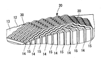
以下、本発明の回転電機のコイル組立体製造方法を具体化した各実施形態について図面を参照しつつ具体的に説明する。最初に、本発明の各実施形態の製造方法により製造されるコイル組立体20を適用した回転電機の固定子10の概略構成について説明する。図1は、コイル組立体20を適用した回転電機の固定子10の外観を示す斜視図であり、(B)は固定子10を側方から見た図である。図2は、固定子10の一部分を拡大して示す斜視図である。
Hereinafter, each embodiment which actualized the coil assembly manufacturing method of the rotary electric machine of the present invention is described concretely, referring to drawings. First, a schematic configuration of the
図1に示す固定子10は、例えば車両の電動機および発電機を兼ねる回転電機に使用される。固定子10は、内周側に回転子(図示せず)を回転自在に収容する。回転子は、永久磁石により周方向に交互に異なる磁極を固定子10の内周側と向き合う外周側に複数形成している。固定子コア12は、所定厚さの磁性鋼板を軸方向に積層して環状に形成されている。固定子コア12には、図2に示すように、軸方向に沿い周方向に隣接するスロット14、15を一組として固定子コア12の内周側の周方向に複数組のスロットが形成されている。固定子巻線としてのコイル組立体20は三相巻線であり、周方向に隣接する一組のスロット14、15に各相の固定子巻線が設置されている。そして、スロット14、15を一組として周方向に隣接する三組のスロット14、15に異なる相の固定子巻線が設置されている。
A
次に、コイル組立体20の構成について説明する。図3は、コイル組立体20の外観を示す斜視図である。図4は、コイル組立体20のコイルエンド部を示す正面図である。図5は、コイル線材30の全体形状を示す正面図である。図6は、コイル線材30の断面図である。図7は、コイル線材30のターン部42の形状を示す斜視図である。
Next, the configuration of the
コイル組立体20のコイル線材30は、図5に示すように、複数のターン部42が所定ピッチで複数形成されたものである。また、コイル線材30は、図6に示すように、銅製の導体32と、導体32の外周を覆い導体32を絶縁する内層34および外層36からなる絶縁被覆とから形成されている。内層34は導体32の外周を覆い、外層36は内層34の外周を覆っている。内層34および外層36を合わせた絶縁被覆の厚みは、100μm〜200μmの間に設定されている。このように、内層34および外層36からなる絶縁被覆の厚みが厚いので、コイル線材30同士を絶縁するためにコイル線材30同士の間に絶縁紙等を挟み込んで絶縁する必要がない。
As shown in FIG. 5, the
外層36は絶縁材、内層34は外層よりもガラス転移温度の高い熱可塑性樹脂またはガラス転移温度の無いポリアミドイミド等の絶縁材で形成されている。これにより、回転電機に発生する熱により外層36は内層34よりも早く軟化するので、同じスロット14に設置されているコイル線材30同士が外層36同士で熱接着する。その結果、同じスロット14に設置されている複数のコイル線材30が一体化しコイル線材30同士が剛体化するので、スロット14内のコイル線材30の機械的強度が向上する。また、過剰な振動が発生しても、内層34と導体32の接着箇所よりも内層34と外層36との接着箇所が先に剥離するので、内層34と導体32との接着を維持し絶縁を確保できる。
The
コイル線材30は、図2に示すように、固定子コア12のスロット14、15内に設置されるスロット収容部40と、スロット14、15から固定子コア12の外に突出し、周方向に異なるスロットに設置されているスロット収容部40同士を接続しているターン部42とを有しており、固定子コア12に波巻されることにより固定子巻線(コイル組立体)20を形成している。ターン部42は固定子コア12の軸方向両側にそれぞれ形成されている。このコイル線材30は、奇数番目のターン部と偶数番目のターン部が、軸線周りの180度位相がずれた位置に交互に設けられている。
As shown in FIG. 2, the
ターン部42の略中央部には、図7に示すように、ねじりを伴わないクランク部44が形成されている。クランク部44は、固定子コア12の端面13に沿ってクランク形状に形成されている。このクランク部44のクランク形状によるずれ量は、線材30の略幅分である。これにより、径方向に隣接している線材30のターン部42同士を密に巻回できる。その結果、コイルエンドの径方向の幅が小さくなるので、コイル組立体20が径方向外側に張り出すことを防止する。
As shown in FIG. 7, a
また、スロット14、15から固定子コア12の外に突出するターン部42の突出箇所に、線材30がまたがって設置されているスロット同士に向けて固定子コア12の軸方向両側の端面13に沿ってクランク部46が形成されている。これにより、スロット14、15から突出している線材30のターン部42の突出箇所の間隔、言い換えればターン部42が形成する三角形状部分の底辺の長さは、コイル線材30がまたがって設置されているスロット同士の間隔よりも狭くなっている。その結果、コイルエンドの高さhが低くなる。
Further, on the end faces 13 on both axial sides of the
また、固定子コア12の端面13に沿ったクランク部46の長さをd1、周方向に隣接するスロット同士の間隔をd2とすると、d1≦d2になっている。これにより、コイル線材30のクランク部46が周方向に隣り合うスロットから突出するコイル線材30と干渉することを防止できる。これにより、周方向に隣接するスロットから突出するコイル線材30同士が互いに干渉することを避けるために、コイルエンドの高さが高くなったり、あるいはコイルエンドの径方向の幅が大きくなったりすることを防止できる。その結果、コイルエンドの高さが低くなる。さらに、コイルエンドの径方向の幅が小さくなるので、コイル組立体20が径方向外側に張り出すことを防止する。
Further, d1 ≦ d2 is satisfied, where d1 is the length of the
さらに、コイル線材30には、ターン部42の略中央部のクランク部44と、ターン部42の突出箇所に形成したクランク部46との間に、それぞれ2個のクランク部48が形成されている。つまり、固定子コア12の一方の軸方向の端面13側のコイル線材30のターン部42には、合計7個のクランク部が形成されている。これにより、クランク部を形成しない三角形状のターン部の高さに比べ、ターン部42の高さhが低くなる。クランク部48のクランク形状も、クランク部44、46と同様に、固定子コア12の端面13に沿ったクランク形状に形成されている。したがって、コイル線材30のターン部42は、クランク部44を挟んで両側を階段状に形成している。
Furthermore, two crank
ここで、三相の固定子巻線としてのコイル組立体20において、回転子の1極当たり各相のコイル線材30は2個のスロット14、15に設置されている。つまり、周方向に連続して隣接しているコイル組立体20の回転子の1極当たりのスロットの総数は3×2=6である。その結果、周方向の異なるスロットにまたがって設置されているコイル線材30は、周方向に6個離れたスロット同士に設置されるので、コイル線材30の略中央部の1個のクランク部44を加え、周方向に隣接しているスロットから突出するコイル線材30同士の干渉を避けるため、(3×2+1)個のクランク部をターン部42に形成することが望ましい。このように固定子コア12の一方の軸方向側のコイルエンドでコイル線材30に7個のクランク部を形成したことにより、コイルエンドの高さを低くし、コイルエンドの径方向の幅を小さくすることができる。
Here, in the
〔実施形態1〕
次に、実施形態1のコイル組立体20の製造方法について、図8〜図13を参照して説明する。本実施形態は、6本のコイル線材が所定の状態に編み込まれて束ねられてなる2束の第1及び第2コイル線材束50、60を用いて編込みを行う方法である。この第1及び第2コイル線材束50、60は、それぞれ6本のコイル線材を所定の状態に編み込んだ後、位置ずれやばらけを防止するために、紐やホルダ等によってその編込み状態を保持するようにされている。
[Embodiment 1]
Next, the manufacturing method of the
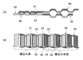
なお、図8〜図13において、それぞれの(A)は平面図であり、それぞれの(B)は正面図である。また、図8は、コイル線材束50、60の一端側(図8の左側)から編込みを開始して、一部分の編込みが終了した時点の状態を示しているが、図8に示す状態が本実施形態の方法における配置工程と同じ状態であるので、図8に示す状態から編込みを開始するものとして説明する。 8 to 13, each (A) is a plan view, and each (B) is a front view. Further, FIG. 8 shows a state at the time when the knitting is started from one end side (the left side in FIG. 8) of the coil wire bundles 50 and 60 and a part of the knitting is finished, but the state shown in FIG. However, since it is the same state as the arrangement | positioning process in the method of this embodiment, it demonstrates as what starts braiding from the state shown in FIG.
本実施形態の製造方法は、配置工程(図8)と、係合工程(図9)と、第1回転工程(図10)と、交差工程(図11)と、第2回転工程(図12)と、移動工程(図13)とを行う。先ず、配置工程では、図8に示すように、第1コイル線材束50と第2コイル線材束60を軸線方向(図8の左右方向)に所定距離(ターン部の約1/2の距離)ずらせると共に、第1及び第2コイル線材束50、60の軸線方向一端側(図8の左側)にある第1ターン部52、61を交差させて対面した状態に並列状に配置する。なお、第1ターン部52、61は、直前の編込み工程で編み込まれた箇所である。
The manufacturing method of this embodiment includes an arrangement step (FIG. 8), an engagement step (FIG. 9), a first rotation step (FIG. 10), a crossing step (FIG. 11), and a second rotation step (FIG. 12). ) And the moving step (FIG. 13). First, in the arranging step, as shown in FIG. 8, the first
この場合、正面側から見て、編込み未完の部分は、第1コイル線材束50が前側に位置し、第2コイル線材束60が後側に位置している。ここで、第1及び第2コイル線材束50、60の並列方向の一方側において最も外側に位置する最外コイル線材束としては、第1及び第2コイル線材束50、60のどちらも該当するが、本実施形態では、第1コイル線材束50を最外コイル線材束とする。
In this case, as viewed from the front side, the first
次の係合工程では、図9に示すように、第1コイル線材束50を平行移動させて、第1コイル線材束50の幅方向一端側(図9の下側)にある第2ターン部52と第2コイル線材束60の軸方向他端側(図9の上側)にある第1ターン部61とを係合させる。
In the next engagement step, as shown in FIG. 9, the first
そして、次の第1回転工程では、図10に示すように、第1コイル線材束50の第2ターン部52と第2コイル線材束60の第1ターン部61との係合部Pを支点として、第1コイル線材束50を第2コイル線材束60と対向する面に沿う方向(矢印a方向)へ相対回転させる。この時、第1コイル線材束50の第4ターン部54と第2コイル線材束60の第3ターン部63とが回転方向(矢印a方向)に所定距離(L)離間した状態になるまで回転させる。この時の第1コイル線材束50の回転角度は、係合部Pを支点としているため小さくすることができる。なお、この時、第2コイル線材束60を第1コイル線材束50の回転方向(矢印a方向)と逆方向へ所定角度回転させてもよい。
In the next first rotation step, as shown in FIG. 10, the engaging portion P between the
次の交差工程では、図11に示すように、係合部Pを支点として、第1コイル線材束50の軸方向他端側(第4ターン部54以降の部分)を、第2コイル線材束60の前側から後側へ移動させて、第1コイル線材束50の第3ターン部53と第2コイル線材束60の第2ターン部62との位置で交差させる。
In the next crossing step, as shown in FIG. 11, the other end side in the axial direction of the first coil wire bundle 50 (the portion after the fourth turn portion 54) is used as the second coil wire bundle with the engaging portion P as a fulcrum. The first
次の第2回転工程では、図12に示すように、係合部Pを支点として、第1コイル線材束50を第1回転工程における回転方向と逆方向(矢印b方向)へ回転させる。これにより、第1コイル線材束50と第2コイル線材束60とが略平行となる状態にする。なお、この時にも、第2コイル線材束60を第1コイル線材束50の回転方向(矢印b方向)と逆方向へ回転させるようにしてもよい。
In the next second rotation step, as shown in FIG. 12, the first
その後、図13に示すように、第1コイル線材束50を第2コイル線材束60と対面する位置へ平行移動させる移動工程行うことにより一連の工程を終了する。これにより、第1コイル線材束50の第3ターン部53と第2コイル線材束60の第2ターン部62とが交差して、第1コイル線材束50の第4ターン部54以降の部分(図13の右側部分)が、第2コイル線材束60を前側から後側へ乗り越えて移動した状態になり、第1コイル線材束50の第3ターン部53が第2コイル線材束60の第2ターン部62に編み込まれた状態になる。
Thereafter, as shown in FIG. 13, a series of steps is completed by performing a moving step of moving the first
なお、上記の移動工程が終了した直後の状態(図13)は、上記の配置工程(図8)の状態から、第1コイル線材束50と第2コイル線材束60との編込み未完の部分(図13の右側部分)が前後方向において入れ替わった状態となっている。即ち、第2コイル線材束60の編込み未完の部分が第1コイル線材束50の前側に位置している。よって、この状態から、第2コイル線材束60に対して、上記の係合工程(図9)から移動工程(図13)までの一連の工程を行うことにより、第1コイル線材束50の第4ターン部54と第2コイル線材束60の第3ターン部63との編込みが行われる。
The state immediately after the moving step is completed (FIG. 13) is an unfinished portion of the first
その後、上記の一連の工程が終了した直後において、編込み未完の部分が前側に位置している第1コイル線材束50又は第2コイル線材束60に対して、上記の一連の工程を同様に繰り返し行うことによって、第1及び第2コイル線材束50、60の一端側から他端側に亘って連続的に、第1及び第2コイル線材束50、60の各ターン部同士の編込みが行われる。なお、この場合、直前に行われた一連の工程で編み込まれた(交差した)状態となったターン部は、次の一連の工程における、第1コイル線材束50の第2ターン部52及び第2コイル線材束60の第1ターン部61として扱われる。
Thereafter, immediately after the above series of steps is completed, the above series of steps is similarly performed on the first
そして、最終的に12本のコイル線材の編込みが完了した場合には、各コイル線材を適宜回転及び平行移動させることにより、各コイル線材の対応するターン部同士が適切な状態で交差して重なり合うように調整して、各コイル線材の端部を複数箇所で接合すると共に、全体をドーナツ状に成形することによって図3に示すコイル組立体20が完成する。
Then, when the braiding of 12 coil wires is finally completed, the corresponding turn portions of each coil wire intersect with each other in an appropriate state by appropriately rotating and translating each coil wire. The
以上のように、本実施形態の製造方法によれば、第1回転工程、交差工程及び第2回転工程を行う際に、第1コイル線材束50の幅方向一端側にあるターン部と第2コイル線材束60の幅方向他端側にあるターン部とが係合する係合部Pを利用している。そのため、特に、第1回転工程において第1コイル線材束50を第2コイル線材束60に対して相対回転させて第1及び第2コイル線材束50、60を開脚させる際の開脚角度を最少にすることができるので、第1及び第2コイル線材束50、60の変形を効果的に回避することができる。
As described above, according to the manufacturing method of the present embodiment, when the first rotation step, the crossing step, and the second rotation step are performed, the turn portion and the second portion on the one end side in the width direction of the first
また、本実施形態の場合には、複数のコイル線材が所定の状態に編み込まれて束ねられた第1及び第2コイル線材束50、60を用いているため、編込み動作中に発生する、コイル線材同士の干渉や引っ掛かり等によるトラブルを有利に回避することができる。よって、多数本のコイル線材の編込みを円滑に且つ容易に行うことができる。 In the case of the present embodiment, since the first and second coil wire bundles 50 and 60 in which a plurality of coil wire rods are knitted and bundled in a predetermined state are used, it occurs during the braiding operation. Troubles due to interference or catching between coil wires can be advantageously avoided. Therefore, a large number of coil wires can be knitted smoothly and easily.
なお、本実施形態では、2本のコイル線材束を用いる場合について説明したが、本実施形態に係る製造方法は、コイル線材束が2本の場合や4本以上の場合にも、適用することができる。また、コイル線材束を構成するコイル線材の本数も、6本に限らず適宜選択することができる。 In addition, although this embodiment demonstrated the case where two coil wire bundles were used, the manufacturing method which concerns on this embodiment is applied also in the case where there are two coil wire bundles or four or more. Can do. Further, the number of coil wire rods constituting the coil wire bundle is not limited to six and can be appropriately selected.
〔実施形態2〕
次に、実施形態2のコイル組立体20の製造方法について、図14〜図19を参照して説明する。本実施形態は、3本の第1〜第3コイル線材70、80、90を用いて編込みを行う方法である。ここで用いる第1〜第3コイル線材70、80、90は、直線状の線材を型のより成形加工することによって、複数のスロット収容部及びターン部が形成されている。
[Embodiment 2]
Next, the manufacturing method of the
なお、図14は、第1〜第3コイル線材70、80、90の一端側(図14の左側)から編込みを開始して、一部分の編込みが終了した時点の状態を示しているが、図14に示す状態は本実施形態の方法における配置工程と同じ状態であるので、図14に示す状態から編込みを開始するものとして説明する。
FIG. 14 shows a state at the time when the knitting is started from one end side (left side in FIG. 14) of the first to third
本実施形態の製造方法は、配置工程(図14)と、係合工程(図15)と、第1回転工程(図16)と、交差工程(図示せず)と、第2回転工程(図17)と、移動工程(図18)とを行う。 The manufacturing method of this embodiment includes an arrangement step (FIG. 14), an engagement step (FIG. 15), a first rotation step (FIG. 16), a crossing step (not shown), and a second rotation step (FIG. 17) and a moving process (FIG. 18).
配置工程では、図14に示すように、第1〜第3コイル線材70、80、90を軸線方向(図14の左右方向)に所定距離(スロットの1ピッチ分)ずらせると共に、第1〜第3コイル線材70、80、90の軸線方向一端側(図14の左側)にある第1ターン部71、81、91を交差させて対面した状態に並列状に配置する。この場合、第1〜第3コイル線材70、80、90の編込み未完の部分は、図14おいて後方側から、第1コイル線材70、第3コイル線材90、第2コイル線材80の順に並んでいる。本実施形態では、各コイル線材の並列方向の一方側において最も外側に位置する最外コイル線材を、第1コイル線材70として説明する。なお、図14は、直前の編込み工程において、第3コイル線材90の第1ターン部91に対して、第2コイル線材80の第1ターン部81の編み込が終了した状態である。よって、この状態から、第2及び第3コイル線材80、90の第1ターン部81、91に対して、第1コイル線材70の第1ターン部71の編込みが開始される。
In the arranging step, as shown in FIG. 14, the first to third
次の係合工程では、図15に示すように、第1コイル線材70を平行移動させて、第1コイル線材70の幅方向一端側(図15の下側)にあるターン部78と、第2及び第3コイル線材80、90の幅方向他端側(図15の上側)にある第1ターン部81、91とを係合させる。この係合部をP2とする。
In the next engagement step, as shown in FIG. 15, the
そして、次の第1回転工程では、図16に示すように、係合部P2を支点として、第1コイル線材70を第2及び第3コイル線材80、90と対向する面に沿う方向(矢印c方向)へ相対回転させる。この時、第1コイル線材70の軸方向他端側と第2及び第3コイル線材80、90の軸方向他端側とが回転方向(矢印c方向)に所定距離(L2)離間した状態になるまで回転させる。この時の第1コイル線材70の回転角度は、係合部P2を支点としてしているため小さくすることができる。なお、この時、第2及び第3コイル線材80、90を第1コイル線材70の回転方向(矢印c方向)と逆方向へ所定角度回転させてもよい。
Then, in the next first rotation step, as shown in FIG. 16, the
次の交差工程では、係合部P2を支点として、第1コイル線材70の軸方向他端側を、第2及び第3コイル線材80、90の後側から前側へ移動させて、第1コイル線材70の第1ターン部71と第2及び第3コイル線材80、90の第2ターン部82、92との位置で交差させる。
In the next crossing step, the
次の第2回転工程では、図17に示すように、係合部P2を支点として、第1コイル線材70を第1回転工程における回転方向と逆方向(矢印d方向)へ回転させる。これにより、第1コイル線材70と第2及び第3コイル線材80、90とが略平行となる状態にする。なお、この時にも、第2及び第3コイル線材80、90を第1コイル線材70の回転方向(矢印d方向)と逆方向へ回転させるようにしてもよい。
In the next second rotation process, as shown in FIG. 17, the
その後、図18に示すように、第1コイル線材70を第2及び第3コイル線材80、90と対面する位置へ平行移動させる移動工程行うことにより一連の工程を終了する。これにより、第1コイル線材70の第1ターン部71と第2及び第3コイル線材80、90の第1ターン部81、91とが交差して、第1コイル線材70の軸方向他端側(図18の右側部分)が、第2及び第3コイル線材80、90を外側から内側へ乗り越えて移動した状態になり、第1コイル線材70の第1ターン部71が第2及び第3コイル線材80、90の第1ターン部81、91に編み込まれた状態になる。
Then, as shown in FIG. 18, a series of process is complete | finished by performing the movement process which translates the
なお、上記の移動工程が終了した直後の状態(図18)は、上記の配置工程(図14)の状態から、第1コイル線材70の編込み未完の部分と、第2及び第3コイル線材80、90との編込み未完の部分(図18の右側部分)が前後方向において入れ替わった状態となっている。即ち、第3コイル線材90の編込み未完の部分が最も後側に位置している。よって、この状態から、第3コイル線材90に対して、上記の係合工程(図14)から移動工程(図18)までの一連の工程を行うことにより、第3コイル線材90の第2ターン部92と第1及び第2コイル線材70、80の第2ターン部72、82との編込みが行われる。
It should be noted that the state immediately after the moving step is completed (FIG. 18) is the same as the arrangement step (FIG. 14) from the unfinished portion of the
その後、上記の一連の工程が終了した直後において、編込み未完の部分が最も後側に位置しているコイル線材束に対して、上記の一連の工程を同様に繰り返し行うことによって、第1〜第3コイル線材70、80、90の一端側から他端側に亘って連続的に、第1〜第3コイル線材70、80、90の各ターン部同士の編込みが行われる(図19参照)。
Then, immediately after the above series of steps is completed, by repeating the above series of steps in the same manner for the coil wire bundle in which the unfinished portion is located on the rearmost side, The braids between the turn portions of the first to third
そして、本実施形態の場合にも、最終的に12本のコイル線材の編込みが完了した場合には、上記のように、各コイル線材を適切な状態に調整して、必要な処置を行った後、全体をドーナツ状に成形することによって図3に示すコイル組立体20が完成する。
And also in the case of this embodiment, when the braiding of 12 coil wires is finally completed, as described above, each coil wire is adjusted to an appropriate state and necessary measures are taken. After that, the whole is formed into a donut shape to complete the
以上のように、本実施形態の製造方法によれば、第1回転工程、交差工程及び第2回転工程を行う際に、第1コイル線材70の幅方向一端側にあるターン部と第2及び第3コイル線材束80、90の幅方向他端側にあるターン部とが係合する係合部Pを利用している。そのため、特に、第1回転工程において第1コイル線材70を第2及び第3コイル線材80、90に対して相対回転させて、第1コイル線材70と第2及び第3コイル線材束80、90とを開脚させる際の開脚角度を最少にすることができるので、第1〜第3コイル線材70、80、90の変形を効果的に回避することができる。
As described above, according to the manufacturing method of the present embodiment, when performing the first rotation step, the crossing step, and the second rotation step, the turn portion on the one end side in the width direction of the
なお、本実施形態では、3本のコイル線材を用いる場合について説明したが、本実施形態に係る製造方法は、コイル線材が2本の場合や4本以上の場合にも、適用することができる。 In addition, although this embodiment demonstrated the case where three coil wires were used, the manufacturing method which concerns on this embodiment is applicable also when the number of coil wires is two, or four or more. .
12…固定子コア 14、15…スロット 20…コイル組立体 30…コイル線材 40…スロット収容部 42…ターン部 50…第1コイル線材束 51…第1ターン部 52…第2ターン部 53…第3ターン部 54…第4ターン部 60…第2コイル線材束 61…第1ターン部 62…第2ターン部 63…第3ターン部 64…第4ターン部 70…第1コイル線材 71…第1ターン部 72…第2ターン部 80…第2コイル線材 81…第1ターン部 82…第2ターン部 90…第3コイル線材 91…第1ターン部 92…第2ターン部
DESCRIPTION OF
Claims (4)
複数の前記コイル線材を軸線方向に所定距離ずらせて対面した状態に並列状に配置すると共に、各前記コイル線材の軸線方向一端側にある各ターン部を交差させた状態に配置する配置工程と、
各前記コイル線材の並列方向の一方側において最も外側に位置する最外コイル線材を平行移動させて、前記最外コイル線材の幅方向一端側にあるターン部と他のコイル線材の幅方向他端側にあるターン部とを係合させる係合工程と、
前記最外コイル線材の幅方向一端側の前記ターン部と他の前記コイル線材の幅方向他端側の前記ターン部との係合部を支点として、前記最外コイル線材を他の前記コイル線材と対向する面に沿う方向へ相対回転させる第1回転工程と、
前記係合部を支点として、前記最外コイル線材の軸方向他端側を、他の前記コイル線材の前記外側から内側へ移動させて他の前記コイル線材と交差させる交差工程と、
前記係合部を支点として、前記最外コイル線材を前記第1回転工程における回転方向と逆方向へ相対回転させる第2回転工程と、
前記最外コイル線材を他の前記コイル線材と対面する位置へ平行移動させる移動工程と、
を有することを特徴とする回転電機のコイル組立体製造方法。 A plurality of coil wire rods having a plurality of slot housing portions formed in a straight line and arranged in parallel, and a plurality of turn portions respectively connecting one end portions and the other end portions of the adjacent slot housing portions. A method of manufacturing a coil assembly of a rotating electrical machine by weaving each other,
An arrangement step of arranging a plurality of the coil wire rods in parallel in a state facing each other by shifting a predetermined distance in the axial direction, and arranging each turn portion on one end side in the axial direction of each of the coil wire rods,
The outermost coil wire located on the outermost side on one side in the parallel direction of each coil wire is translated, and the turn portion on one end side in the width direction of the outermost coil wire and the other end in the width direction of the other coil wire An engagement step for engaging the turn part on the side;
The outermost coil wire is used as another coil wire, with an engaging portion between the turn portion at one end in the width direction of the outermost coil wire and the turn portion at the other end in the width direction of the other coil wire as a fulcrum. A first rotation step of relative rotation in a direction along the surface facing the
Using the engaging portion as a fulcrum, a crossing step of moving the other end side in the axial direction of the outermost coil wire from the outside to the inside of the other coil wire and intersecting with the other coil wire,
A second rotation step in which the outermost coil wire is relatively rotated in a direction opposite to the rotation direction in the first rotation step, with the engaging portion as a fulcrum;
A moving step of translating the outermost coil wire to a position facing the other coil wire;
A coil assembly manufacturing method for a rotating electrical machine, comprising:
複数の前記コイル線材が所定の状態に束ねられてなる複数のコイル線材束を、軸線方向に所定距離ずらせて対面した状態に並列状に配置すると共に、各前記コイル線材束の軸線方向一端側にある各ターン部を交差させた状態に配置する配置工程と、
各前記コイル線材束の並列方向の一方側において最も外側に位置する最外コイル線材束を平行移動させて、前記最外コイル線材束の幅方向一端側にあるターン部と他のコイル線材束の幅方向他端側にあるターン部とを係合させる係合工程と、
前記最外コイル線材束の幅方向一端側の前記ターン部と他の前記コイル線材束の幅方向他端側の前記ターン部との係合部を支点として、前記最外コイル線材束を他の前記コイル線材束と対向する面に沿う方向へ相対回転させる第1回転工程と、
前記係合部を支点として、前記最外コイル線材束の軸方向他端側を、他の前記コイル線材束の前記外側から内側へ移動させて他の前記コイル線材束と交差させる交差工程と、
前記係合部を支点として、前記最外コイル線材束を前記第1回転工程における回転方向と逆方向へ相対回転させる第2回転工程と、
前記最外コイル線材束を他の前記コイル線材束と対面する位置へ平行移動させる移動工程と、
を有することを特徴とする回転電機のコイル組立体製造方法。 A plurality of coil wire rods having a plurality of slot housing portions formed in a straight line and arranged in parallel, and a plurality of turn portions respectively connecting one end portions and the other end portions of the adjacent slot housing portions. A method of manufacturing a coil assembly of a rotating electrical machine by weaving each other,
A plurality of coil wire bundles in which a plurality of coil wire rods are bundled in a predetermined state are arranged in parallel so as to face each other with a predetermined distance shifted in the axial direction, and at one end in the axial direction of each coil wire bundle An arrangement step of arranging each turn part in a crossed state;
The outermost coil wire bundle positioned on the outermost side on one side in the parallel direction of each of the coil wire bundles is translated, and the turn portion on one end side in the width direction of the outermost coil wire bundle and the other coil wire bundle An engagement step for engaging the turn portion on the other end side in the width direction;
The outermost coil wire bundle is used as a fulcrum at the engaging portion between the turn portion on one end side in the width direction of the outermost coil wire bundle and the turn portion on the other end side in the width direction of the other coil wire bundle. A first rotation step of relatively rotating in a direction along the surface facing the coil wire bundle,
Using the engaging portion as a fulcrum, the crossing step of moving the other end side in the axial direction of the outermost coil wire bundle from the outside to the inside of the other coil wire bundle and intersecting with the other coil wire bundle,
A second rotation step of rotating the outermost coil wire bundle in a direction opposite to the rotation direction in the first rotation step, with the engaging portion as a fulcrum;
A moving step of translating the outermost coil wire bundle to a position facing the other coil wire bundle;
A coil assembly manufacturing method for a rotating electrical machine, comprising:
Priority Applications (2)
| Application Number | Priority Date | Filing Date | Title |
|---|---|---|---|
| JP2008171586A JP5201400B2 (en) | 2008-06-30 | 2008-06-30 | Method for manufacturing coil assembly of rotating electrical machine |
| US12/493,419 US8091206B2 (en) | 2008-06-30 | 2009-06-29 | Method of twisting coil wire to make coil assembly for use in electric rotary machine |
Applications Claiming Priority (1)
| Application Number | Priority Date | Filing Date | Title |
|---|---|---|---|
| JP2008171586A JP5201400B2 (en) | 2008-06-30 | 2008-06-30 | Method for manufacturing coil assembly of rotating electrical machine |
Publications (2)
| Publication Number | Publication Date |
|---|---|
| JP2010011714A true JP2010011714A (en) | 2010-01-14 |
| JP5201400B2 JP5201400B2 (en) | 2013-06-05 |
Family
ID=41445754
Family Applications (1)
| Application Number | Title | Priority Date | Filing Date |
|---|---|---|---|
| JP2008171586A Active JP5201400B2 (en) | 2008-06-30 | 2008-06-30 | Method for manufacturing coil assembly of rotating electrical machine |
Country Status (2)
| Country | Link |
|---|---|
| US (1) | US8091206B2 (en) |
| JP (1) | JP5201400B2 (en) |
Cited By (4)
| Publication number | Priority date | Publication date | Assignee | Title |
|---|---|---|---|---|
| JP2012085484A (en) * | 2010-10-14 | 2012-04-26 | Denso Corp | Method of manufacturing coil assembly for rotary electric machine |
| JP2012110105A (en) * | 2010-11-16 | 2012-06-07 | Denso Corp | Method for manufacturing coil assembly for rotary electric machine |
| JP2012110106A (en) * | 2010-11-16 | 2012-06-07 | Denso Corp | Method for manufacturing coil assembly for rotary electric machine |
| JP2014073058A (en) * | 2012-10-02 | 2014-04-21 | Denso Corp | Method for manufacturing coil assembly |
Families Citing this family (11)
| Publication number | Priority date | Publication date | Assignee | Title |
|---|---|---|---|---|
| JP4873261B2 (en) * | 2007-11-20 | 2012-02-08 | 株式会社デンソー | Method for manufacturing coil assembly of rotating electrical machine |
| US9118225B2 (en) | 2012-08-24 | 2015-08-25 | Caterpillar Inc. | Coil with twisted wires and stator assembly of a rotary electric machine |
| FR3020205B1 (en) * | 2014-04-17 | 2017-11-03 | Valeo Equip Electr Moteur | METHOD FOR MAKING AN ELECTRIC MACHINE STATOR COIL COMPRISING A PREFORMING STEP AND CORRESPONDING COIL STATOR |
| FR3020206B1 (en) * | 2014-04-17 | 2017-11-03 | Valeo Equip Electr Moteur | METHOD FOR MAKING A STATOR OF A FRONT-REAR TYPE ELECTRIC MACHINE STATOR AND CORRESPONDING COIL STATOR |
| US20160013693A1 (en) * | 2014-07-08 | 2016-01-14 | Hamilton Sundstrand Corporation | Strand layout for reduced ac winding loss |
| US10347414B2 (en) * | 2015-05-14 | 2019-07-09 | Maxlinear, Inc. | Method and system for winding transformers to maximize symmetry of the primary and secondary coils |
| KR20210031762A (en) * | 2018-08-10 | 2021-03-22 | 보그워너 인크. | Methods of weaving windings of electromechanical components |
| CN112534691B (en) | 2018-08-10 | 2023-12-12 | 博格华纳公司 | Method for winding a component of an electric machine |
| DE112019004070T5 (en) | 2018-08-10 | 2021-06-02 | Borgwarner Inc. | METHOD OF FORMING A COMPONENT FOR AN ELECTRICAL MACHINE |
| DE102021130257B4 (en) | 2021-11-19 | 2023-07-06 | Aumann Espelkamp Gmbh | Method and device for producing a woven winding mat for a coil winding of an electrical machine |
| EP4213353A1 (en) * | 2022-01-14 | 2023-07-19 | Grob-Werke GmbH & Co. KG | Device and method of manufacturing an inserted wave winding |
Citations (3)
| Publication number | Priority date | Publication date | Assignee | Title |
|---|---|---|---|---|
| JP2000139048A (en) * | 1998-05-20 | 2000-05-16 | Denso Corp | Rotating machine and manufacture |
| JP2003244906A (en) * | 2001-12-13 | 2003-08-29 | Asmo Co Ltd | Manufacturing method for rotating electric machine and rotating electric machine |
| JP2004104841A (en) * | 2002-09-04 | 2004-04-02 | Mitsubishi Electric Corp | Manufacturing method for rotating machine and winding assembly, and manufacturing device for its winding member |
Family Cites Families (1)
| Publication number | Priority date | Publication date | Assignee | Title |
|---|---|---|---|---|
| JP3707606B2 (en) | 2000-02-07 | 2005-10-19 | 三菱電機株式会社 | Winding assembly of rotating electrical machine, manufacturing method thereof, and stator of rotating electrical machine using the winding assembly |
-
2008
- 2008-06-30 JP JP2008171586A patent/JP5201400B2/en active Active
-
2009
- 2009-06-29 US US12/493,419 patent/US8091206B2/en active Active
Patent Citations (3)
| Publication number | Priority date | Publication date | Assignee | Title |
|---|---|---|---|---|
| JP2000139048A (en) * | 1998-05-20 | 2000-05-16 | Denso Corp | Rotating machine and manufacture |
| JP2003244906A (en) * | 2001-12-13 | 2003-08-29 | Asmo Co Ltd | Manufacturing method for rotating electric machine and rotating electric machine |
| JP2004104841A (en) * | 2002-09-04 | 2004-04-02 | Mitsubishi Electric Corp | Manufacturing method for rotating machine and winding assembly, and manufacturing device for its winding member |
Cited By (4)
| Publication number | Priority date | Publication date | Assignee | Title |
|---|---|---|---|---|
| JP2012085484A (en) * | 2010-10-14 | 2012-04-26 | Denso Corp | Method of manufacturing coil assembly for rotary electric machine |
| JP2012110105A (en) * | 2010-11-16 | 2012-06-07 | Denso Corp | Method for manufacturing coil assembly for rotary electric machine |
| JP2012110106A (en) * | 2010-11-16 | 2012-06-07 | Denso Corp | Method for manufacturing coil assembly for rotary electric machine |
| JP2014073058A (en) * | 2012-10-02 | 2014-04-21 | Denso Corp | Method for manufacturing coil assembly |
Also Published As
| Publication number | Publication date |
|---|---|
| US8091206B2 (en) | 2012-01-10 |
| JP5201400B2 (en) | 2013-06-05 |
| US20090320275A1 (en) | 2009-12-31 |
Similar Documents
| Publication | Publication Date | Title |
|---|---|---|
| JP5201400B2 (en) | Method for manufacturing coil assembly of rotating electrical machine | |
| JP4873261B2 (en) | Method for manufacturing coil assembly of rotating electrical machine | |
| JP4577588B2 (en) | Method for manufacturing coil assembly of rotating electrical machine | |
| JP4505764B2 (en) | Method for manufacturing coil assembly of rotating electrical machine | |
| JP5332347B2 (en) | Coil wire rod for coil assembly of rotating electrical machine | |
| JP5167939B2 (en) | Method for manufacturing coil assembly of rotating electrical machine | |
| JP5234173B2 (en) | Stator and method of manufacturing unit coil used therein | |
| JP2009011152A (en) | Stator of rotating electric machine | |
| JP5321983B2 (en) | Stator, rotating electric machine, and winding method | |
| WO2012169059A1 (en) | Stator of rotating electric machine, manufacturing method of stator of rotating electric machine, and rotating electric machine | |
| JP5152578B2 (en) | Method for manufacturing coil assembly of rotating electrical machine | |
| JP5177545B2 (en) | Method for manufacturing coil assembly of rotating electrical machine | |
| JP5625788B2 (en) | Method for manufacturing coil assembly of rotating electrical machine | |
| JP5359463B2 (en) | Stator and rotating electric machine | |
| JP5483111B2 (en) | Manufacturing method of stator winding for rotating electric machine | |
| JP5435293B2 (en) | Method for manufacturing coil assembly of rotating electrical machine | |
| JP2013070522A (en) | Armature for rotary electric machine and manufacturing method thereof | |
| JP6331978B2 (en) | Stator winding manufacturing method | |
| JP2013118764A (en) | Stator manufacturing method and stator manufacturing apparatus | |
| JP2010136597A (en) | Motor and winding method for the same | |
| JP2005304108A (en) | Stator of rotary motor, method for applying coil of rotary motor, coil winder | |
| JP5569743B2 (en) | Method for manufacturing coil assembly of rotating electrical machine | |
| JP5915150B2 (en) | Helical wound sheet coil |
Legal Events
| Date | Code | Title | Description |
|---|---|---|---|
| A621 | Written request for application examination |
Free format text: JAPANESE INTERMEDIATE CODE: A621 Effective date: 20110413 |
|
| TRDD | Decision of grant or rejection written | ||
| A01 | Written decision to grant a patent or to grant a registration (utility model) |
Free format text: JAPANESE INTERMEDIATE CODE: A01 Effective date: 20130117 |
|
| A977 | Report on retrieval |
Free format text: JAPANESE INTERMEDIATE CODE: A971007 Effective date: 20130123 |
|
| A61 | First payment of annual fees (during grant procedure) |
Free format text: JAPANESE INTERMEDIATE CODE: A61 Effective date: 20130130 |
|
| R151 | Written notification of patent or utility model registration |
Ref document number: 5201400 Country of ref document: JP Free format text: JAPANESE INTERMEDIATE CODE: R151 |
|
| FPAY | Renewal fee payment (event date is renewal date of database) |
Free format text: PAYMENT UNTIL: 20160222 Year of fee payment: 3 |
|
| R250 | Receipt of annual fees |
Free format text: JAPANESE INTERMEDIATE CODE: R250 |
|
| R250 | Receipt of annual fees |
Free format text: JAPANESE INTERMEDIATE CODE: R250 |
|
| R250 | Receipt of annual fees |
Free format text: JAPANESE INTERMEDIATE CODE: R250 |
|
| R250 | Receipt of annual fees |
Free format text: JAPANESE INTERMEDIATE CODE: R250 |
|
| R250 | Receipt of annual fees |
Free format text: JAPANESE INTERMEDIATE CODE: R250 |
|
| R250 | Receipt of annual fees |
Free format text: JAPANESE INTERMEDIATE CODE: R250 |
|
| R250 | Receipt of annual fees |
Free format text: JAPANESE INTERMEDIATE CODE: R250 |
|
| R250 | Receipt of annual fees |
Free format text: JAPANESE INTERMEDIATE CODE: R250 |
|
| R250 | Receipt of annual fees |
Free format text: JAPANESE INTERMEDIATE CODE: R250 |