JP2010011346A - Receiving device, receiving method and wireless communication system - Google Patents
Receiving device, receiving method and wireless communication system Download PDFInfo
- Publication number
- JP2010011346A JP2010011346A JP2008171142A JP2008171142A JP2010011346A JP 2010011346 A JP2010011346 A JP 2010011346A JP 2008171142 A JP2008171142 A JP 2008171142A JP 2008171142 A JP2008171142 A JP 2008171142A JP 2010011346 A JP2010011346 A JP 2010011346A
- Authority
- JP
- Japan
- Prior art keywords
- transfer function
- unit
- signal
- radio signal
- cross
- Prior art date
- Legal status (The legal status is an assumption and is not a legal conclusion. Google has not performed a legal analysis and makes no representation as to the accuracy of the status listed.)
- Granted
Links
Images


Classifications
-
- H—ELECTRICITY
- H04—ELECTRIC COMMUNICATION TECHNIQUE
- H04L—TRANSMISSION OF DIGITAL INFORMATION, e.g. TELEGRAPHIC COMMUNICATION
- H04L7/00—Arrangements for synchronising receiver with transmitter
- H04L7/04—Speed or phase control by synchronisation signals
- H04L7/041—Speed or phase control by synchronisation signals using special codes as synchronising signal
- H04L7/042—Detectors therefor, e.g. correlators, state machines
Abstract
Description
本発明は、受信装置、受信方法、および無線通信システムに関する。 The present invention relates to a receiving device, a receiving method, and a wireless communication system.
近日、IEEE(Institute of Electrical and Electronic Engineers)802.11に規定される無線通信装置が広く普及している。このような無線通信装置間における無線通信の流れを簡単に以下に示す。
(1)送信側の無線通信装置におけるRF(Radio Frequency)送信処理
(2)RF送信処理により得られた高周波信号を無線信号として無線伝送路を介して送信
(3)受信側の無線通信装置における無線信号の受信およびRF受信処理
(4)RF受信処理により得られた受信信号と、既知信号パターンとの相互相関演算
(5)相互相関が検出されたタイミングに基づく受信信号の復調、復号処理
Recently, wireless communication devices defined by IEEE (Institut of Electrical and Electronic Engineers) 802.11 are widely used. The flow of wireless communication between such wireless communication devices is briefly shown below.
(1) RF (Radio Frequency) transmission processing in the wireless communication device on the transmission side (2) High-frequency signal obtained by the RF transmission processing is transmitted as a wireless signal through the wireless transmission path (3) In the wireless communication device on the reception side Radio signal reception and RF reception processing (4) Cross-correlation calculation between reception signal obtained by RF reception processing and known signal pattern (5) Demodulation and decoding processing of reception signal based on timing at which cross-correlation is detected
ここで、上記(4)の相互相関演算についてより詳細に説明すると、送信側の無線通信装置は、既知信号パターンであるL−LTFを含む無線信号を送信する。そして、受信側の無線通信装置は、RF受信処理により得られた受信信号に含まれるL−LTFと、既知信号パターンであるL−LTFとの相互相関を演算することにより、同期タイミングを検出する。なお、相互相関演算については、例えば特許文献1に記載されている。 Here, the cross-correlation calculation (4) will be described in more detail. The transmitting-side wireless communication apparatus transmits a wireless signal including L-LTF that is a known signal pattern. Then, the wireless communication device on the receiving side detects the synchronization timing by calculating the cross-correlation between the L-LTF included in the received signal obtained by the RF reception processing and the L-LTF that is a known signal pattern. . The cross-correlation calculation is described in, for example, Patent Document 1.
しかし、RF受信処理により得られた受信信号に含まれるL−LTFは、既知信号パターンとして受信側の無線通信装置が保持しているL−LTFと異なる。これは、送信側の無線通信装置におけるRF送信処理、無線伝送路、受信側の無線通信装置におけるRF受信処理などにおいて、L−LTFに伝達関数が混入してしまうことに起因する。その結果、上記(4)の相互相関演算における相互相関の演算精度が劣化してしまうという問題があった。 However, the L-LTF included in the reception signal obtained by the RF reception process is different from the L-LTF held by the reception-side wireless communication apparatus as a known signal pattern. This is because the transfer function is mixed into the L-LTF in the RF transmission process in the wireless communication apparatus on the transmission side, the wireless transmission path, the RF reception process in the wireless communication apparatus on the reception side, and the like. As a result, there is a problem that the calculation accuracy of the cross-correlation in the cross-correlation calculation (4) is deteriorated.
そこで、本発明は、上記問題に鑑みてなされたものであり、本発明の目的とするところは、相互相関の演算精度を向上することが可能な、新規かつ改良された受信装置、受信方法、および無線通信システムを提供することにある。 Therefore, the present invention has been made in view of the above problems, and an object of the present invention is to provide a new and improved receiving apparatus, receiving method, which can improve the calculation accuracy of cross-correlation, And providing a wireless communication system.
上記課題を解決するために、本発明のある観点によれば、無線信号を受信する受信部と、前記無線信号の通信経路の伝達関数を推定する伝達関数推定部と、前記受信部により受信される無線信号に含まれる同期信号と、前記伝達関数推定部により推定された伝達関数が乗算された既知の同期信号との相互相関を演算する相互相関演算部と、を備える受信装置が提供される。 In order to solve the above problem, according to an aspect of the present invention, a reception unit that receives a radio signal, a transfer function estimation unit that estimates a transfer function of a communication path of the radio signal, and the reception unit receive the radio signal. And a cross-correlation calculation unit that calculates a cross-correlation between the synchronization signal included in the radio signal and the known synchronization signal multiplied by the transfer function estimated by the transfer function estimation unit. .
前記受信装置は、前記既知の同期信号を記憶している記憶部と、前記記憶部に記憶されている前記既知の同期信号に、前記伝達関数推定部により推定された伝達関数を乗算する補正部と、をさらに備えてもよい。 The receiving device includes a storage unit that stores the known synchronization signal, and a correction unit that multiplies the known synchronization signal stored in the storage unit by the transfer function estimated by the transfer function estimation unit. And may be further provided.
前記記憶部は、前記伝達関数推定部により推定された伝達関数を前記無線信号の送信元装置と対応付けて記憶し、前記補正部は、前記受信部により受信された無線信号の送信元装置の伝達関数を前記記憶部から抽出し、当該伝達関数を前記既知の同期信号に乗算してもよい。 The storage unit stores the transfer function estimated by the transfer function estimation unit in association with the wireless signal transmission source device, and the correction unit stores the wireless signal transmission source device received by the reception unit. A transfer function may be extracted from the storage unit, and the transfer function may be multiplied by the known synchronization signal.
前記受信装置は、前記既知の同期信号に、前記伝達関数推定部により推定された伝達関数を乗算する補正部と、前記補正部により前記伝達関数が乗算された前記既知の同期信号を記憶する記憶部と、をさらに備えてもよい。 The receiver stores a correction unit that multiplies the known synchronization signal by the transfer function estimated by the transfer function estimation unit, and a memory that stores the known synchronization signal obtained by multiplying the transfer function by the correction unit. And a section.
前記伝達関数推定部は、以降に連続的に無線信号が送信されることを示す情報を含む第1の無線信号に基づいて前記伝達関数を推定し、前記相互相関演算部は、前記第1の無線信号の以降に連続的に送信される第2の無線信号に含まれる同期信号と、前記伝達関数推定部において前記第1の無線信号に基づいて推定された伝達関数が乗算された前記既知の同期信号との相互相関を演算してもよい。 The transfer function estimation unit estimates the transfer function based on a first radio signal including information indicating that the radio signal is continuously transmitted thereafter, and the cross-correlation calculation unit The known signal obtained by multiplying the synchronization signal included in the second radio signal continuously transmitted after the radio signal and the transfer function estimated based on the first radio signal in the transfer function estimation unit You may calculate the cross correlation with a synchronizing signal.
前記通信路の伝達関数には、前記無線信号の無線伝送路の伝達関数、前記受信部の伝達関数、または前記無線信号の送信元装置の伝達関数の少なくともいずれかが含まれてもよい。 The transfer function of the communication path may include at least one of a transfer function of a radio transmission path of the radio signal, a transfer function of the receiving unit, or a transfer function of a transmission source device of the radio signal.
また、上記課題を解決するために、本発明の別の観点によれば、無線信号を受信する第1のステップと、前記無線信号の通信経路の伝達関数を推定する第2のステップと、無線信号を受信する第3のステップと、前記第3のステップにおいて受信した無線信号に含まれる同期信号と、前記第2のステップにおいて推定された伝達関数が乗算された既知の同期信号との相互相関を演算するステップと、を含む受信方法が提供される。 In order to solve the above problem, according to another aspect of the present invention, a first step of receiving a radio signal, a second step of estimating a transfer function of a communication path of the radio signal, and a radio A cross-correlation between a third step of receiving a signal, a synchronization signal included in the radio signal received in the third step, and a known synchronization signal multiplied by the transfer function estimated in the second step A receiving method is provided.
また、上記課題を解決するために、本発明の別の観点によれば、無線信号を送信する送信装置と、前記送信装置から送信された無線信号を受信する受信部、前記無線信号の通信経路の伝達関数を推定する伝達関数推定部、および前記受信部により受信される無線信号に含まれる同期信号と、前記伝達関数推定部により推定された伝達関数が乗算された既知の同期信号との相互相関を演算する相互相関演算部、を有する受信装置と、を備える無線通信システムが提供される。 In order to solve the above problems, according to another aspect of the present invention, a transmission device that transmits a radio signal, a reception unit that receives a radio signal transmitted from the transmission device, and a communication path of the radio signal A transfer function estimating unit that estimates a transfer function of the signal, a synchronization signal included in a radio signal received by the receiving unit, and a known synchronization signal multiplied by the transfer function estimated by the transfer function estimating unit There is provided a wireless communication system including a receiving device having a cross-correlation calculating unit that calculates a correlation.
以上説明したように本発明にかかる受信装置、受信方法、および無線通信システムによれば、相互相関の演算精度を向上することができる。 As described above, according to the receiving apparatus, the receiving method, and the radio communication system according to the present invention, it is possible to improve the calculation accuracy of the cross correlation.
以下に添付図面を参照しながら、本発明の好適な実施の形態について詳細に説明する。なお、本明細書及び図面において、実質的に同一の機能構成を有する構成要素については、同一の符号を付することにより重複説明を省略する。 Exemplary embodiments of the present invention will be described below in detail with reference to the accompanying drawings. In addition, in this specification and drawing, about the component which has the substantially same function structure, duplication description is abbreviate | omitted by attaching | subjecting the same code | symbol.
また、以下に示す項目順序に従って当該「発明を実施するための最良の形態」を説明する。
〔1〕本実施形態に関連する無線通信システム
〔2〕本発明の第1の実施形態
〔2−1〕本発明の第1の実施形態にかかる無線通信装置の構成
〔2−2〕本発明の第1の実施形態にかかる無線通信装置の動作
〔3〕本発明の第2の実施形態
〔4〕まとめ
Further, the “best mode for carrying out the invention” will be described according to the following item order.
[1] Radio communication system related to this embodiment [2] First embodiment of the present invention [2-1] Configuration of radio communication apparatus according to the first embodiment of the present invention [2-2] Present invention Operation of the wireless communication apparatus according to the first embodiment of the present invention [3] Second embodiment of the present invention [4] Summary
〔1〕本実施形態に関連する無線通信システム
まず、本実施形態を説明する前に、本実施形態に関連する無線通信システム11について説明する。
[1] Radio Communication System Related to the Present Embodiment First, before describing the present embodiment, the radio communication system 11 related to the present embodiment will be described.
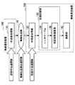
図1は、本実施形態に関連する無線通信システム11の構成を示した説明図である。図1に示したように、無線通信システム11は、複数の無線通信装置100および100’と、無線伝送路16とを含む。また、図1においては、無線通信装置100’が送信側として機能し、無線通信装置100が受信側として機能する例を示している。
FIG. 1 is an explanatory diagram showing a configuration of a wireless communication system 11 related to the present embodiment. As shown in FIG. 1, the wireless communication system 11 includes a plurality of
図1に示したように、無線通信装置100’は、ベースバンドの送信信号をRF送信処理して高周波信号に変換するRF送信処理部110を備える。RF送信処理部110によりRF送信処理された送信信号は、無線伝送路16を介して無線信号として送信される。ここで、無線通信装置100’から送信される無線信号の先頭には、図2に示すプリアンブルが付加される。
As illustrated in FIG. 1, the
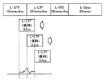
図2は、プリアンブルの構成例を示した説明図である。図2に示したように、プリアンブルは、L−STF(Short Traning Field)と、L−LTF(Long Traning Field)と、L−SIGと、を含み、その後にデータ(L−Data)が付加される。本明細書においては、このようにプリアンブルとデータを含む1単位をパケットと称する場合もある。 FIG. 2 is an explanatory diagram showing a configuration example of a preamble. As shown in FIG. 2, the preamble includes an L-STF (Short Running Field), an L-LTF (Long Translating Field), and an L-SIG, and data (L-Data) is added after that. The In the present specification, one unit including a preamble and data is sometimes referred to as a packet.
L−STF(第1の同期信号)では、周期が0.8μsである既知信号パターンが10回繰り返され、受信側ではかかるL−STFに基づいて無線信号の受信を検出する。L−LTF(第2の同期信号)では、周期が3.2μsである既知信号パターンの後半部分(1.6μs)の後に、当該信号パターンが2回繰り返される(計8μs)。すなわち、L−LTF先頭に付加される信号パターンの後半部分はガードインターバルとして機能する。 In L-STF (first synchronization signal), a known signal pattern with a period of 0.8 μs is repeated 10 times, and the reception side detects reception of a radio signal based on the L-STF. In L-LTF (second synchronization signal), the signal pattern is repeated twice (8 μs in total) after the latter half (1.6 μs) of the known signal pattern having a period of 3.2 μs. That is, the latter half of the signal pattern added to the L-LTF head functions as a guard interval.
L−SIGは、当該フレームに含まれるデータの伝送速度や変調方式などの情報を含む。このようなプリアンブルは、事前に時間領域の信号として無線通信装置100’に保持されており、無線通信装置100’は、保持しているプリアンブルを送信信号の先頭に付加してもよい。 The L-SIG includes information such as a transmission rate and a modulation method of data included in the frame. Such a preamble is held in advance in the radio communication apparatus 100 'as a time domain signal, and the radio communication apparatus 100' may add the held preamble to the head of the transmission signal.
ここで、図1を参照して本実施形態に関連する無線通信システム11の説明に戻る。無線通信装置100は、RF受信処理部120、L−LTFテーブル134および相互相関演算部138を含む同期回路部130、および復調部140を備える。
Here, referring back to FIG. 1, the description returns to the wireless communication system 11 related to the present embodiment. The
RF受信処理部120は、無線伝送路16を介して無線通信装置100に到達した無線信号をRF受信処理し、ベースバンドの受信信号に変換する。L−LTFテーブル134には、図2に示したL−LTFの信号パターンが保持されており、相互相関演算部138は、受信信号に含まれるL−LTFと、L−LTFテーブル134に保持されているL−LTFとの相互相関を演算する。以下、図3を参照し、相互相関の演算について簡単に説明する。
The RF
図3は、相互相関演算を概念的に示した説明図である。上記説明したように、相互相関演算部138は、L−LTFテーブル134に保持されている3.2μs分のL−LTFと、受信信号のうちでL−LTFと推定される部分付近との相互相関を演算する。ここで、図3に示したように、受信信号に含まれるL−LTFの先頭が相互相関のピーク値となると考えられるため、相互相関演算部138は、L−LTFの先頭を相互相関のピーク値により検出することができる。なお、L−LTFにおいては、同一の信号パターンが繰り返されるためピーク値が複数現れることも想定されるが、相互相関演算部138が、図3に示したようにL−LTFの先頭のみを検出するよう構成される例を説明している。
FIG. 3 is an explanatory diagram conceptually showing the cross-correlation calculation. As described above, the
相互相関演算部138によりL−LTFの先頭が検出されると、復調部140などにより、受信信号の復調および復号がL−LTFの先頭の検出タイミング(同期タイミング)に基づいて行なわれる。したがって、相互相関演算部138によるL−LTFの先頭の検出精度は受信信号の正確な復調および復号のために重要である。しかし、本実施形態に関連する無線通信システム11においては、L−LTFの先頭を適確に検出できない場合があった。以下、その理由を説明する。
When the start of the L-LTF is detected by the
図1に示したように、送信信号は、RF送信処理部110の伝達関数(送信RF伝達関数)が乗算され、無線伝送路の伝達関数が乗算され、RF受信処理部120の伝達関数(受信RF伝達関数)が乗算されて同期回路部130へ入力される。したがって、同期回路部130へ入力される受信信号Yは、送信信号をX、送信RF伝達関数をαtx、無線伝送路の伝達関数をαp、受信RF伝達関数をαrxとすると、以下の数式1のように表現される。
As shown in FIG. 1, the transmission signal is multiplied by the transfer function of the RF transmission processing unit 110 (transmission RF transfer function), multiplied by the transfer function of the wireless transmission path, and the transfer function (reception of the RF reception processing unit 120). RF transfer function) is multiplied and input to the
![]()
![]()
このため、受信信号に含まれるL−LTFと、L−LTFテーブル134に保持されているL−LTFが一致せず、図4に示すように、相互相関演算部138がL−LTFの先頭を適確に検出できない場合が想定された。
For this reason, the L-LTF included in the received signal and the L-LTF held in the L-LTF table 134 do not match, and the
図4は、相互相関演算の失敗例を示した説明図である。図4に示したように、受信信号に含まれるL−LTFが各伝達関数の影響を受けることにより、L−LTFの先頭においてピーク値が現れない場合が想定された。また、受信信号に含まれるL−LTFが各伝達関数の影響を受けることにより、L−LTFの先頭と異なる位置でピーク値が現れ、L−LTFの先頭が誤って検出されてしまう場合も想定された。その結果、復調部140などで正しい処理が行われず、スループットの低下やコネクションの切断などの問題が発生しかねなかった。
FIG. 4 is an explanatory view showing a failure example of the cross-correlation calculation. As shown in FIG. 4, it is assumed that the peak value does not appear at the head of the L-LTF due to the influence of each transfer function on the L-LTF included in the received signal. Further, it is assumed that the L-LTF included in the received signal is affected by each transfer function, so that a peak value appears at a position different from the head of the L-LTF and the head of the L-LTF is erroneously detected. It was done. As a result, correct processing is not performed in the
そこで、上記事情を一着眼点にして本実施形態にかかる無線通信装置20を創作するに至った。本実施形態にかかる無線通信装置20によれば、相互相関の演算精度を向上することにより、L−LTFの先頭をより適確に検出することが可能である。以下、このような無線通信装置20の第1の実施形態および第2の実施形態について順次に説明する。
Accordingly, the
〔2〕本発明の第1の実施形態
〔2−1〕本発明の第1の実施形態にかかる無線通信装置の構成
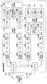
図5は、本発明の第1の実施形態にかかる無線通信システム1の構成、および無線通信装置20の構成を示した説明図である。図5に示したように、無線通信システム1は複数の無線通信装置20および20’を含む。なお、以下では無線通信装置20’が送信側として機能し、無線通信装置20が受信側として機能する例に重きをおいて説明するが、無線通信装置20および20’は、送信側としての機能および受信側としての機能の双方を有する。
[2] First Embodiment of the Present Invention [2-1] Configuration of the Wireless Communication Device According to the First Embodiment of the Present Invention FIG. 5 shows the configuration of the wireless communication system 1 according to the first embodiment of the present invention. 2 is an explanatory diagram showing a configuration and a configuration of a
無線通信装置20は、アンテナ12Aおよび12B、セレクタ18Aおよび18B、MAC処理部30、変調部32、送信信号処理部40、信号パターン保持部42、IFFT部52Aおよび52B、送信フィルタ54Aおよび54B、DAC56Aおよび56B、RF送信処理部58Aおよび58B、RF受信処理部60Aおよび60B、ADC62Aおよび62B、受信フィルタ64Aおよび64B、同期回路部70、FFT部72Aおよび72B、チャネル推定部74Aおよび74B、RF伝達関数推定部76、信号合成部80、および復調部92を備える。
The
なお、本明細書においては、同一機能を有する複数の構成の各々は、同一符号の後に異なるアルファベットを付することで区別する。しかし、同一機能を有する複数の構成の各々を特に区別する必要が無い場合、同一符号のみを付する。例えば、IFFT部52Aおよび52Bを特に区別する必要が無い場合、単にIFFT部52と総称する。
In the present specification, each of a plurality of components having the same function is distinguished by attaching a different alphabet after the same symbol. However, when it is not necessary to distinguish each of a plurality of configurations having the same function, only the same reference numerals are given. For example,
MAC(Medium Access Control)処理部30は無線通信におけるアクセス制御を行う。例えば、MAC処理部30は、送信データに対して自装置のMACアドレス、宛先装置のMACアドレスなどの制御情報を付加し、ビット列として出力する。
A MAC (Medium Access Control)
変調部32は、MAC処理部30から出力されたビット列を変調する。例えば、変調部32は、無線伝送路16の状況に応じ、BPSK(Binary Phase Shift Keying)、QPSK、16QAM、64QAM、256QAM、8PSKなどのいずれかの変調方式により変調を行なってもよい。また、変調部32は、OFDM(Orthogonal Frequency Division Multiplexing)方式を実現するために、各サブキャリアに割当てられたビットごとに変調してもよい。
The
送信信号処理部40は、変調部32から出力されたビット列のMIMO送信処理を行う。MIMO送信処理としては、例えば、各ブランチへのビット列の割り振り、ビームフォーミングなどがあげられる。
The transmission
IFFT(Inverse Fast Fourier Transform)部52は、送信信号処理部40における信号処理により得られた周波数領域の信号を、高速逆フーリエ変換することにより、時間領域の送信信号(OFDM信号)に変換する。送信フィルタ54は、IFFT部52において得られた時間領域の送信信号から、所定の周波数成分を抽出する。なお、当該時間領域の送信信号にはガードインターバルが付加されていてもよい。
An IFFT (Inverse Fast Fourier Transform) unit 52 converts a frequency domain signal obtained by signal processing in the transmission
DAC(デジタル/アナログ変換部)56は、送信フィルタ54により抽出された周波数成分を有する送信信号を、デジタル形式からアナログ形式に変換する。そして、RF送信処理部58が、アナログ形式に変換された送信信号を例えばIQ変調し、高周波信号(例えば、5GHz帯)に変換する。
The DAC (digital / analog conversion unit) 56 converts the transmission signal having the frequency component extracted by the transmission filter 54 from a digital format to an analog format. Then, the RF
セレクタ18は、アンテナ12(受信部)と、RF送信処理部58またはRF受信処理部60のいずれかを接続する。アンテナ12とRF送信処理部58がセレクタ18により接続されると、RF送信処理部58において得られた高周波信号がアンテナ12から無線信号として送信され、無線通信装置20が送信装置として機能する。また、アンテナ12とRF受信処理部60がセレクタ18により接続されると、アンテナ12において受信された無線信号が高周波信号としてRF受信処理部60へ供給され、無線通信装置20が受信装置として機能する。
The selector 18 connects the antenna 12 (reception unit) and either the RF
RF受信処理部60は、アンテナ12から入力される高周波信号をダウンコンバーションし、アナログ形式のベースバンド受信信号(受信信号)を生成する。
The RF
ADC(アナログ/デジタル変換部)62は、RF受信処理部60により生成されたアナログ形式のベースバンド受信信号をデジタル形式のベースバンドの受信信号に変換して出力する。受信フィルタ64は、ADC62から出力されるデジタル形式のベースバンド受信信号に含まれる所定の周波数成分を抽出する。
The ADC (analog / digital conversion unit) 62 converts the analog baseband reception signal generated by the RF
同期回路部70は、図2を参照して説明したL−STFを検出するための自己相関演算部210、およびL−LTFを検出するための相互相関演算部220を備え、プリアンブルに続くパケットフレームの切り出しのための同期タイミングを検出する。なお、当該同期回路部70の構成については図6を参照して後述する。
The
FFT部72は、同期回路部70により検出された同期タイミングに基づいてパケットフレームを切り出し、切り出したパケットフレームごとにFFT処理を行い、周波数領域の受信信号を生成する。そして、チャネル推定部74は、無線信号の伝送路である無線伝送路16の伝達関数を推定する伝達関数推定部としての機能を有する。なお、チャネル推定部74により推定される伝達関数には、送信元装置である無線通信装置20’の伝達関数が含まれてもよい。また、詳細については後述するが、RF伝達関数推定部76は、RF受信処理部60の伝達関数を推定する。
The
信号合成部80は、チャネル推定部74およびRF伝達関数推定部76により推定された伝達関数を考慮してMIMO受信処理を行う。例えば、信号合成部80は、チャネル推定部74から出力される信号に、チャネル推定部74およびRF伝達関数推定部76により推定された伝達関数(例えば、チャネル行列H)の逆行列を乗算してもよい。
The
復調部92は、信号合成部80により得られた信号を復調し、ビット列として出力する。MAC処理部30は、復調部92からビット列が入力され、ビット列に含まれる制御情報を解析するとともに、ビット列に含まれる制御情報以外の情報を上位層へ供給する。
The
以上、無線通信装置20が送信装置として機能するための基本構成、および受信装置として機能するための基本構成について説明した。続いて、無線通信装置20においてキャリブレーションを行なうための信号パターン保持部42およびRF伝達関数推定部76について説明する。なお、キャリブレーションの対象としては、以下に示すものがあげられ、これらを対象とするキャリブレーションの一例として、IQキャリブレーションおよびアンテナキャリブレーションについて説明する。
・送信フィルタ54、RF送信処理部58内のアナログフィルタ、RF受信処理部60内のアナログフィルタなどの周波数特性を有する構成
・DAC56、ADC62などのアパーチャ効果と関連する構成
・PA(ゲインが非線形性である構成)
・IQモジュレータ、IQデモジュレータ(IQインバランスを生じる構成)
・配長線の違い
・無線通信装置間の周波数誤差成分
In the above, the basic configuration for the
A configuration having frequency characteristics such as an analog filter in the transmission filter 54 and the RF
IQ modulator, IQ demodulator (configuration that generates IQ imbalance)
・ Different distribution lines ・ Frequency error components between wireless communication devices
(IQキャリブレーションについて)
IQキャリブレーションは、送信側のIQキャリブレーションと受信側のIQキャリブレーションに分けられる。送信側のIQキャリブレーションは、主にDAC56とRF送信処理部58内のIQモジュレータのキャリブレーションを目的としている。送信側のIQキャリブレーションに際しては、信号パターン保持部42に保持されている既定のキャリブレーションデータが送信フィルタ54Aへ供給され、RF送信処理部58内のIQモジュレータとADC62が接続される。
(About IQ calibration)
IQ calibration is divided into IQ calibration on the transmission side and IQ calibration on the reception side. The IQ calibration on the transmission side is mainly intended for calibration of the DAC 56 and the IQ modulator in the RF
その結果、DAC56からIQモジュレータにキャリブレーションデータが入力されると、IQモジュレータによりキャリブレーションデータがIQ変調され、さらに整流、絶対値化されてADC62へ入力される。 As a result, when calibration data is input from the DAC 56 to the IQ modulator, the calibration data is IQ-modulated by the IQ modulator, further rectified and converted into an absolute value, and input to the ADC 62.
RF伝達関数推定部76は、ADC62を介して帰還されたキャリブレーションデータを観測することにより、送信側のIQ振幅誤差およびIQ位相誤差を補正するための補正係数を取得することができる。
The RF transfer
一方、受信側のIQキャリブレーションは、主にRF受信処理部60内のIQデモジュレータとADC62のキャリブレーションを目的としている。受信側のIQキャリブレーションに際しては、RF送信処理部58内のIQモジュレータとRF受信処理部60内のIQデモジュレータが接続される。
On the other hand, the IQ calibration on the receiving side is mainly intended for calibration of the IQ demodulator in the RF
その結果、DAC56からIQモジュレータにキャリブレーションデータが入力されると、IQモジュレータによりIQ変調されたキャリブレーションデータがIQデモジュレータに入力される。IQデモジュレータは入力された信号をダウンコンバージョンし、ADC62を介してRF伝達関数推定部76に帰還させる。
As a result, when calibration data is input from the DAC 56 to the IQ modulator, calibration data IQ-modulated by the IQ modulator is input to the IQ demodulator. The IQ demodulator down-converts the input signal and feeds it back to the RF transfer
ここで、送信側のIQインバランスは既に補正されているので、帰還された信号からは、受信側のIQインバランスの影響のみ観測することが可能となる。RF伝達関数推定部76は、かかる帰還された信号から受信側の伝達関数としてのIQ振幅誤差とIQ位相誤差を見積り、その誤差に応じた補正係数を取得することが可能となる。
Here, since the IQ imbalance on the transmission side has already been corrected, only the influence of the IQ imbalance on the reception side can be observed from the fed back signal. The RF
(アンテナキャリブレーションについて)
アンテナキャリブレーションは、RF送信処理部58内のアナログフィルタやアンテナ12などの伝達関数のインバランスの解消を目的としており、通常IQキャリブレーションの後に行われる。詳細な説明は省略するが、まず、アンテナキャリブレーションにおいては、アンテナ12Aから送信したキャリブレーションデータをアンテナ12Bが受信してRF伝達関数推定部76へ帰還させる。その後、アンテナ12Bから送信したキャリブレーションデータをアンテナ12Aが受信してRF伝達関数推定部76へ帰還させる。そして、RF伝達関数推定部76が、帰還された双方のキャリブレーションデータに基づいてRF送信処理部58内のアナログフィルタやアンテナ12などの伝達関数の推定、および補正係数の算出を行なう。
(About antenna calibration)
The antenna calibration is intended to eliminate imbalance of transfer functions such as the analog filter and the antenna 12 in the RF
(同期回路部70について)
次に、図6および図7を参照し、同期回路部70についてより詳細に説明する。
(About the synchronization circuit unit 70)
Next, the
図6は、同期回路部70の詳細な構成、および無線通信装置20の一部の構成を示した機能ブロック図である。図6に示したように、同期回路部70は、自己相関演算部210と、相互相関演算部220と、L−LTFテーブル230と、L−LTF補正部240と、を備える。
FIG. 6 is a functional block diagram illustrating a detailed configuration of the
自己相関演算部210は、受信信号と、所定時間遅延させた受信信号との自己相関を演算することにより、L−STFの開始、またはL−STFの終了などを検出する。例えば、自己相関演算部210は、受信信号をL−STFにおける信号パターンの繰り返し周期である0.8μs遅延させ、現在入力された受信信号と、遅延された受信信号の複素共役とを乗算してもよい。L−STFが終了すると自己相関値が減少するため、自己相関演算部210はかかる自己相関値の減少によりL−STFの終了、およびL−LTFの開始を検出することができる。
相互相関演算部220は、受信信号と、L−LTF補正部240から供給されるL−LTFとの相互相関を演算することにより、以降の処理で利用される同期タイミングを検出する。
The
L−LTFテーブル230は、既知信号パターンの同期信号であるL−LTFを記憶している記憶部として機能する。かかるL−LTFテーブル230は、例えば、レジスタ、不揮発性メモリ、磁気ディスク、または光ディスクなどの記憶媒体であってもよい。不揮発性メモリとしては、EEPROM(Electrically Erasable Programmable Read−Only Memory)、EPROM(Erasable Programmable ROM)などがあげられる。また、磁気ディスクとしては、ハードディスク、円盤型磁性体ディスク、MO(Magneto Optical)ディスクなどがあげられる。また、光ディスクとしては、CD(Compact Disc)、DVD(Digital Versatile Disc Recordable)およびBD(Blu−Ray Disc(登録商標))―R/BD−REなどがあげられる。 The L-LTF table 230 functions as a storage unit that stores L-LTF, which is a synchronization signal of a known signal pattern. The L-LTF table 230 may be a storage medium such as a register, a nonvolatile memory, a magnetic disk, or an optical disk. Examples of the nonvolatile memory include an EEPROM (Electrically Erasable Programmable Read-Only Memory) and an EPROM (Erasable Programmable ROM). Examples of the magnetic disk include a hard disk, a disk-type magnetic disk, and an MO (Magneto Optical) disk. Examples of the optical disk include a CD (Compact Disc), a DVD (Digital Versatile Disc Recordable), and a BD (Blu-Ray Disc (registered trademark))-R / BD-RE.
L−LTF補正部240(補正部)は、送信元装置に応じてL−LTFテーブル230に保持されているL−LTFを補正し、相互相関演算部220へ供給する。以下では、送信元装置の判別方法、および具体的な補正方法について説明する。
The L-LTF correction unit 240 (correction unit) corrects the L-LTF held in the L-LTF table 230 according to the transmission source device and supplies the L-LTF to the
(送信元装置の判別方法)
送信元装置は、送信データが1パケットに収まらない場合、複数のパケットをSIFS(16μs)またはRIFS(2μs)間隔でバースト的に送信する(バースティングモード)。また、送信元装置は、バースティングモード時、パケットのMACヘッダに含まれるACKポリシーというフィールドにその旨を記載する。また、MACヘッダには、送信元装置のアドレスが記載される。
(Sending device identification method)
When the transmission data does not fit in one packet, the transmission source apparatus transmits a plurality of packets in bursts at SIFS (16 μs) or RIFS (2 μs) intervals (bursting mode). Further, in the bursting mode, the transmission source device describes that fact in a field called ACK policy included in the MAC header of the packet. The MAC header describes the address of the transmission source device.
したがって、無線通信装置20のMAC処理部30は、MACヘッダに含まれるACKポリシーを参照することにより、次に受信されるパケットの送信元装置を判断することができる。
Therefore, the
なお、ACKポリシーは、ACKパケットの送信を要求するか否かを示すフィールドである。例えば、バースト的に送信された最後のパケットでのみACKパケットの送信が要求される。このため、無線通信装置20のMAC処理部30は、あるパケット(第1の無線信号)ACKポリシーにおいてACKパケットの送信が要求されていない場合、次に受信されるパケット(第2の無線信号)の送信元装置も同一であると判断する。
The ACK policy is a field indicating whether or not transmission of an ACK packet is requested. For example, transmission of an ACK packet is requested only in the last packet transmitted in bursts. For this reason, the
(L−LTFの補正方法)
送信元装置のRF送信処理部58の伝達関数および無線伝送路16の伝達関数(以下、チャネル伝達関数と称する。)は、同一の送信元装置および同一の無線伝送路16であれば、大きな変動は無い。そこで、L−LTF補正部240は、一度受信したパケットの送信元装置と対応付けて、当該送信元装置のチャネル伝達関数を保持しておく。
(L-LTF correction method)
The transfer function of the RF
そして、L−LTF補正部240は、MAC処理部30により判断された次に受信されるパケットの送信元装置に対応するチャネル伝達関数を検索する。ここで、L−LTF補正部240は、次に受信されるパケットの送信元装置に対応するチャネル伝達関数を保持していた場合、当該チャネル伝達関数およびRF伝達関数推定部76により推定された伝達関数を、L−LTFテーブル230のL−LTFに乗算する。その後、L−LTF補正部240は、乗算による補正後のL−LTFを相互相関演算部220へ供給する。
Then, the L-
図7は、本実施形態にかかる相互相関演算の様子を模式的に示した説明図である。図7に示したように、相互相関演算部220は、チャネル伝達関数および受信RF伝達関数を考慮して補正されたL−LTFを利用して相互相関を演算する。このため、本実施形態によれば、受信されたパケットにチャネル伝達関数や受信RF伝達関数が混入していた場合であっても、相互相関演算部220における同期タイミングの検出精度の向上を図ることができる。その結果、復調部92におけるより正確な復調処理が期待されるため、スループットが低下してしまう場合や、コネクションが切断してしまう場合を防止することが可能である。
FIG. 7 is an explanatory diagram schematically showing the state of cross-correlation calculation according to the present embodiment. As shown in FIG. 7, the
なお、「(送信元装置の判別方法)」において説明したように、MAC処理部30は、バースティングモード時に最初に受信されたパケットの送信元装置を、当該パケットの相互相関演算時に把握することは困難である。このため、L−LTF補正部240は、バースティングモード時に最初に受信されたパケットについては、送信元装置に依存しない受信RF伝達関数を利用してL−LTFを補正し、相互相関演算部220に補正後のL−LTFを供給してもよい。
Note that, as described in “(Determination method of transmission source device)”, the
また、上記では、L−LTF補正部240が送信元装置ごとにチャネル伝達関数を保持しておく例を説明したが、本発明はかかる例に限定されない。例えば、L−LTF補正部240は、チャネル伝達関数の乗算による補正後のL−LTFを送信元装置ごとに保持していてもよい。かかる構成によれば、受信時にL−LTFの補正処理を行わなくてよいため、より迅速に相互相関演算部220へ補正後のL−LTFを供給することが可能となる。
In the above description, the example in which the L-
また、無線通信装置20と送信元装置との初期位相の相違により、チャネル伝達関数の推定値が正確に得られない場合がある。そこで、無線通信装置20は、初期位相が、0度、45度、90度、135度、180度、225度、270度、315度である場合の各々で自己相関値を求め、最もピークが鋭く現れる組合せを選択して同期タイミングとしてもよい。
In addition, the estimated value of the channel transfer function may not be obtained accurately due to the difference in the initial phase between the
〔2−2〕本発明の第1の実施形態にかかる無線通信装置の動作
以上、図5〜図7を参照し、本発明の第1の実施形態にかかる無線通信装置の機能を説明した。続いて、図8を参照し、本発明の第1の実施形態にかかる無線通信装置の動作を説明する。
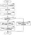
[2-2] Operation of Wireless Communication Device According to First Embodiment of Present Invention The function of the wireless communication device according to the first embodiment of the present invention has been described above with reference to FIGS. Next, the operation of the wireless communication apparatus according to the first embodiment of the present invention will be described with reference to FIG.
図8は、本発明の第1の実施形態にかかる無線通信装置の動作の流れを示したフローチャートである。図8に示したように、まず、無線通信装置20のRF伝達関数推定部76は、キャリブレーションにより、RF受信処理部60やADC62などが有するRF伝達関数を推定する(S304)。続いて、無線通信装置20が無線信号を受信すると(S308)、チャネル推定部74が、送信元装置のRF送信処理部58の伝達関数および無線伝送路16の伝達関数を含むチャネル伝達関数を推定する(S312)。L−LTF補正部240は、チャネル推定部74により推定されたチャネル伝達関数を、送信元装置と対応付けて保持しておく。
FIG. 8 is a flowchart showing an operation flow of the wireless communication apparatus according to the first embodiment of the present invention. As shown in FIG. 8, first, the RF transfer
その後、L−LTF補正部240は、チャネル伝達関数を保持している送信元装置から無線信号を受信する場合(S316)、L−LTFテーブル230のL−LTFを、該当するチャネル伝達関数および受信RF伝達関数を用いて補正する(S320)。そして、相互相関演算部220が、L−LTF補正部240による補正後のL−LTFと、無線信号に含まれるL−LTFとの相互相関を演算することにより同期タイミングを検出する(S324)。
After that, when receiving a radio signal from the transmission source device holding the channel transfer function (S316), the L-
一方、L−LTF補正部240は、チャネル伝達関数を保持していない送信元装置から無線信号を受信する場合(S316)、L−LTFテーブル230に保持されているL−LTFを相互相関演算部220に供給する(S328)。そして、相互相関演算部220は、L−LTFテーブルに保持されているL−LTFと、無線信号に含まれるL−LTFとの相互相関を演算することにより同期タイミングを検出する。なお、L−LTF補正部240は、チャネル伝達関数を保持していない送信元装置から無線信号を受信する場合(S316)、L−LTFテーブル230のL−LTF受信RF伝達関数を用いて補正して相互相関演算部220に供給してもよい。
On the other hand, when receiving a radio signal from a transmission source device that does not hold the channel transfer function (S316), the L-
〔3〕本発明の第2の実施形態
次に、図9を参照し、本発明の第2の実施形態を説明する。図9は、本発明の第2の実施形態にかかる同期回路部71の構成、および無線通信装置20のその他の構成の一部を示した機能ブロック図である。本発明の第2の実施形態にかかる無線通信装置20は、第1の実施形態と実質的に同一の機能も包含するため、以下では、第1の実施形態と異なる機能に重きをおいて説明する。
[3] Second Embodiment of the Present Invention Next, a second embodiment of the present invention will be described with reference to FIG. FIG. 9 is a functional block diagram illustrating a configuration of the
図9に示したように、本実施形態にかかる同期回路部71は、自己相関演算部210と、相互相関演算部220と、L−LTFテーブル232と、を備える。
As shown in FIG. 9, the
自己相関演算部210は、受信信号と、所定時間遅延させた受信信号との自己相関を演算することにより、L−STFの開始、またはL−STFの終了などを検出する。また、相互相関演算部220は、受信信号と、L−LTFテーブル232から供給されるL−LTFとの相互相関を演算することにより、以降の処理で利用される同期タイミングを検出する。
第1の実施形態においては、無線信号の通信経路の伝達関数として、送信元装置のRF送信処理部58の伝達関数、無線伝送路16の伝達関数、RF受信処理部60などの伝達関数を利用する例を説明したが、本実施形態ではRF受信処理部60の伝達関数を利用する。
In the first embodiment, the transfer function of the RF
具体的には、L−LTFテーブル232は、RF受信処理部60の伝達関数を含む受信RF伝達関数による補正後のL−LTFを保持している。なお、当該補正は、L−LTF補正部242が、RF伝達関数推定部76により推定された受信RF伝達関数に基づいて行う。
Specifically, the L-LTF table 232 holds the L-LTF corrected by the reception RF transfer function including the transfer function of the RF
かかる構成によれば、第1の実施形態よりは相互相関の演算精度が落ちるが、何の補正もされていないL−LTFを用いて相互相関演算を行なう本実施形態に関連する無線通信装置100よりは同期特性を向上することが可能である。
According to this configuration, although the cross-correlation calculation accuracy is lower than in the first embodiment, the
〔4〕まとめ
以上説明したように、本発明の第1の実施形態によれば、相互相関演算部220が、チャネル伝達関数および受信RF伝達関数を考慮して補正されたL−LTFを利用して相互相関を演算する。このため、本発明の第1の実施形態態によれば、受信された無線信号にチャネル伝達関数や受信RF伝達関数が混入していた場合であっても、相互相関演算部220における同期タイミングの検出精度の向上を図ることができる。その結果、復調部92におけるより正確な復調処理が期待されるため、スループットが低下してしまう場合や、コネクションが切断してしまう場合を防止することが可能である。
[4] Summary As described above, according to the first embodiment of the present invention, the
なお、第2の実施形態において説明したように、受信された無線信号に混入している伝達関数の一部を考慮してL−LTFを補正してもよい。このような本発明の第2の実施形態によれば、第1の実施形態よりは相互相関の演算精度が落ちるが、何の補正もされていないL−LTFを用いて相互相関演算を行なう本実施形態に関連する無線通信装置100よりは同期特性を向上することが可能である。
As described in the second embodiment, the L-LTF may be corrected in consideration of a part of the transfer function mixed in the received radio signal. According to the second embodiment of the present invention, the cross-correlation calculation accuracy is lower than that of the first embodiment, but the cross-correlation calculation is performed using an L-LTF that has not been corrected. The synchronization characteristic can be improved as compared with the
なお、添付図面を参照しながら本発明の好適な実施形態について説明したが、本発明は係る例に限定されないことは言うまでもない。当業者であれば、特許請求の範囲に記載された範疇内において、各種の変更例または修正例に想到し得ることは明らかであり、それらについても当然に本発明の技術的範囲に属するものと了解される。 In addition, although preferred embodiment of this invention was described referring an accompanying drawing, it cannot be overemphasized that this invention is not limited to the example which concerns. It will be apparent to those skilled in the art that various changes and modifications can be made within the scope of the claims, and these are naturally within the technical scope of the present invention. Understood.
例えば、上記実施形態ではチャネル推定部74およびRF伝達関数推定部76を異なる構成として説明したが、チャネル伝達関数および受信RF伝達関数を併せて推定可能な構成を無線通信装置20に設けてもよい。
For example, in the above embodiment, the
また、上記第1の実施形態では、受信RF伝達関数が補正されていない状態で受信信号が同期回路部70に入力される例を説明したが、本発明はかかる例に限定されない。例えば、無線通信装置20は、受信RF伝達関数を補正した状態で受信信号を同期回路部70に入力してもよい。この場合、L−LTF補正部240は、L−LTFテーブル230のL−LTFをチャネル伝達関数を利用し、受信RF伝達関数を利用せずに補正して相互相関演算部220へ供給してもよい。
In the first embodiment, the example in which the reception signal is input to the
また、本明細書の無線通信装置20の処理における各ステップは、必ずしもフローチャートとして記載された順序に沿って時系列に処理する必要はない。例えば、無線通信装置20の処理における各ステップは、並列的あるいは個別に実行される処理(例えば、並列処理あるいはオブジェクトによる処理)を含んでもよい。
In addition, each step in the processing of the
12 アンテナ
20 無線通信装置
30 MAC処理部
42 信号パターン保持部
52 IFFT部
60 RF受信処理部
62 ADC
64 受信フィルタ
70、71 同期回路部
72 FFT部
74 チャネル推定部
76 RF伝達関数推定部
92 復調部
210 自己相関演算部
220 相互相関演算部
230、232 L−LTFテーブル
240、242 L−LTF補正部
12
64
Claims (8)
前記無線信号の通信経路の伝達関数を推定する伝達関数推定部と;
前記受信部により受信される無線信号に含まれる同期信号と、前記伝達関数推定部により推定された伝達関数が乗算された既知の同期信号との相互相関を演算する相互相関演算部と;
を備える、受信装置。 A receiver for receiving radio signals;
A transfer function estimator for estimating a transfer function of a communication path of the radio signal;
A cross-correlation calculation unit that calculates a cross-correlation between a synchronization signal included in a radio signal received by the reception unit and a known synchronization signal multiplied by the transfer function estimated by the transfer function estimation unit;
A receiving device.
前記既知の同期信号を記憶している記憶部と;
前記記憶部に記憶されている前記既知の同期信号に、前記伝達関数推定部により推定された伝達関数を乗算する補正部と;
をさらに備える、請求項1に記載の受信装置。 The receiving device is:
A storage unit storing the known synchronization signal;
A correction unit that multiplies the known synchronization signal stored in the storage unit by the transfer function estimated by the transfer function estimation unit;
The receiving device according to claim 1, further comprising:
前記補正部は、前記受信部により受信された無線信号の送信元装置と対応付けられている伝達関数を前記記憶部から抽出し、当該伝達関数を前記既知の同期信号に乗算する、請求項2に記載の受信装置。 The storage unit stores the transfer function estimated by the transfer function estimation unit in association with the wireless signal transmission source device,
The correction unit extracts a transfer function associated with a transmission source device of a radio signal received by the receiving unit from the storage unit, and multiplies the known synchronization signal by the transfer function. The receiving device described in 1.
前記既知の同期信号に、前記伝達関数推定部により推定された伝達関数を乗算する補正部と;
前記補正部により前記伝達関数が乗算された前記既知の同期信号を記憶する記憶部と;
をさらに備える、請求項1に記載の受信装置。 The receiving device is:
A correction unit that multiplies the known synchronization signal by the transfer function estimated by the transfer function estimation unit;
A storage unit for storing the known synchronization signal multiplied by the transfer function by the correction unit;
The receiving device according to claim 1, further comprising:
前記相互相関演算部は、前記第1の無線信号の以降に連続的に送信される第2の無線信号に含まれる同期信号と、前記伝達関数推定部において前記第1の無線信号に基づいて推定された伝達関数が乗算された前記既知の同期信号との相互相関を演算する、請求項1に記載の受信装置。 The transfer function estimation unit estimates the transfer function based on a first radio signal including information indicating that the radio signal is continuously transmitted thereafter,
The cross-correlation calculating unit estimates based on the synchronization signal included in the second radio signal continuously transmitted after the first radio signal and the first radio signal in the transfer function estimation unit The receiving apparatus according to claim 1, wherein a cross-correlation with the known synchronization signal multiplied by the determined transfer function is calculated.
前記無線信号の通信経路の伝達関数を推定する第2のステップと;
無線信号を受信する第3のステップと;
前記第3のステップにおいて受信した無線信号に含まれる同期信号と、前記第2のステップにおいて推定された伝達関数が乗算された既知の同期信号との相互相関を演算するステップと;
を含む、受信方法。 A first step of receiving a radio signal;
A second step of estimating a transfer function of a communication path of the wireless signal;
A third step of receiving a radio signal;
Calculating a cross-correlation between the synchronization signal included in the radio signal received in the third step and the known synchronization signal multiplied by the transfer function estimated in the second step;
Including a receiving method.
前記送信装置から送信された無線信号を受信する受信部、
前記無線信号の通信経路の伝達関数を推定する伝達関数推定部、および、
前記受信部により受信される無線信号に含まれる同期信号と、前記伝達関数推定部により推定された伝達関数が乗算された既知の同期信号との相互相関を演算する相互相関演算部、
を有する受信装置と;
を備える、無線通信システム。
A transmitting device for transmitting a radio signal;
A receiver for receiving a radio signal transmitted from the transmitter;
A transfer function estimator for estimating a transfer function of a communication path of the radio signal; and
A cross-correlation calculation unit that calculates a cross-correlation between a synchronization signal included in a radio signal received by the reception unit and a known synchronization signal multiplied by the transfer function estimated by the transfer function estimation unit;
A receiving device having:
A wireless communication system.
Priority Applications (2)
| Application Number | Priority Date | Filing Date | Title |
|---|---|---|---|
| JP2008171142A JP4623151B2 (en) | 2008-06-30 | 2008-06-30 | Reception device, reception method, and wireless communication system |
| US12/492,746 US8270350B2 (en) | 2008-06-30 | 2009-06-26 | Receiving apparatus, receiving method and wireless communication system |
Applications Claiming Priority (1)
| Application Number | Priority Date | Filing Date | Title |
|---|---|---|---|
| JP2008171142A JP4623151B2 (en) | 2008-06-30 | 2008-06-30 | Reception device, reception method, and wireless communication system |
Publications (2)
| Publication Number | Publication Date |
|---|---|
| JP2010011346A true JP2010011346A (en) | 2010-01-14 |
| JP4623151B2 JP4623151B2 (en) | 2011-02-02 |
Family
ID=41447305
Family Applications (1)
| Application Number | Title | Priority Date | Filing Date |
|---|---|---|---|
| JP2008171142A Expired - Fee Related JP4623151B2 (en) | 2008-06-30 | 2008-06-30 | Reception device, reception method, and wireless communication system |
Country Status (2)
| Country | Link |
|---|---|
| US (1) | US8270350B2 (en) |
| JP (1) | JP4623151B2 (en) |
Cited By (4)
| Publication number | Priority date | Publication date | Assignee | Title |
|---|---|---|---|---|
| JP2011228890A (en) * | 2010-04-19 | 2011-11-10 | Ricoh Co Ltd | Radio communication equipment and reception signal processing method |
| WO2012042875A1 (en) * | 2010-09-28 | 2012-04-05 | 三洋電機株式会社 | Receiving device |
| WO2013011973A1 (en) * | 2011-07-19 | 2013-01-24 | 川崎マイクロエレクトロニクス株式会社 | I/q mismatch compensation method and rf transceiver |
| JP2017533626A (en) * | 2014-09-16 | 2017-11-09 | クゥアルコム・インコーポレイテッドQualcomm Incorporated | Frame structure for mixed-rate wireless communication networks |
Families Citing this family (3)
| Publication number | Priority date | Publication date | Assignee | Title |
|---|---|---|---|---|
| US8116397B2 (en) * | 2009-10-20 | 2012-02-14 | Freescale Semiconductor, Inc. | System and method for symbol boundary detection in orthogonal frequency divison multiplexing based data communication |
| WO2012101722A1 (en) | 2011-01-27 | 2012-08-02 | 三洋電機株式会社 | Reception device |
| EP3314832A4 (en) * | 2015-06-25 | 2019-01-30 | Applied Micro Circuits Corporation | Calibration of high-speed interleaved arrays |
Citations (3)
| Publication number | Priority date | Publication date | Assignee | Title |
|---|---|---|---|---|
| JPH10200503A (en) * | 1997-01-09 | 1998-07-31 | Matsushita Electric Ind Co Ltd | Adaptive equalizing circuit for spread spectrum communication |
| JP2005348235A (en) * | 2004-06-04 | 2005-12-15 | Ntt Docomo Inc | Array antenna receiver and transmitter |
| JP2007208719A (en) * | 2006-02-02 | 2007-08-16 | Nippon Telegr & Teleph Corp <Ntt> | Channel information feedback method and radio communication apparatus |
Family Cites Families (6)
| Publication number | Priority date | Publication date | Assignee | Title |
|---|---|---|---|---|
| US6026130A (en) * | 1997-03-04 | 2000-02-15 | Advanced Micro Devices, Inc. | System and method for estimating a set of parameters for a transmission channel in a communication system |
| JP2001053654A (en) * | 1999-08-16 | 2001-02-23 | Matsushita Electric Ind Co Ltd | Signal separating device, signal separation method and recording medium |
| US7916803B2 (en) * | 2003-04-10 | 2011-03-29 | Qualcomm Incorporated | Modified preamble structure for IEEE 802.11a extensions to allow for coexistence and interoperability between 802.11a devices and higher data rate, MIMO or otherwise extended devices |
| JP2006050573A (en) * | 2004-06-28 | 2006-02-16 | Sanyo Electric Co Ltd | Transmitting method and apparatus, and receiving method and apparatus |
| US20060203894A1 (en) * | 2005-03-10 | 2006-09-14 | Nokia Corporation | Method and device for impulse response measurement |
| JP2007324729A (en) | 2006-05-30 | 2007-12-13 | Sony Corp | Receiving method and receiver |
-
2008
- 2008-06-30 JP JP2008171142A patent/JP4623151B2/en not_active Expired - Fee Related
-
2009
- 2009-06-26 US US12/492,746 patent/US8270350B2/en not_active Expired - Fee Related
Patent Citations (3)
| Publication number | Priority date | Publication date | Assignee | Title |
|---|---|---|---|---|
| JPH10200503A (en) * | 1997-01-09 | 1998-07-31 | Matsushita Electric Ind Co Ltd | Adaptive equalizing circuit for spread spectrum communication |
| JP2005348235A (en) * | 2004-06-04 | 2005-12-15 | Ntt Docomo Inc | Array antenna receiver and transmitter |
| JP2007208719A (en) * | 2006-02-02 | 2007-08-16 | Nippon Telegr & Teleph Corp <Ntt> | Channel information feedback method and radio communication apparatus |
Cited By (9)
| Publication number | Priority date | Publication date | Assignee | Title |
|---|---|---|---|---|
| JP2011228890A (en) * | 2010-04-19 | 2011-11-10 | Ricoh Co Ltd | Radio communication equipment and reception signal processing method |
| WO2012042875A1 (en) * | 2010-09-28 | 2012-04-05 | 三洋電機株式会社 | Receiving device |
| US8649454B2 (en) | 2010-09-28 | 2014-02-11 | Sanyo Electric Co., Ltd. | Receiving apparatus that receives packet signal in which a known signal is placed in the beginning of packet signal |
| JP2016029813A (en) * | 2010-09-28 | 2016-03-03 | パナソニックIpマネジメント株式会社 | Reception device |
| JP5887560B2 (en) * | 2010-09-28 | 2016-03-16 | パナソニックIpマネジメント株式会社 | Receiver |
| WO2013011973A1 (en) * | 2011-07-19 | 2013-01-24 | 川崎マイクロエレクトロニクス株式会社 | I/q mismatch compensation method and rf transceiver |
| JPWO2013011973A1 (en) * | 2011-07-19 | 2015-02-23 | 株式会社メガチップス | IQ mismatch correction method and RF transceiver |
| JP2017533626A (en) * | 2014-09-16 | 2017-11-09 | クゥアルコム・インコーポレイテッドQualcomm Incorporated | Frame structure for mixed-rate wireless communication networks |
| KR101904005B1 (en) | 2014-09-16 | 2018-10-04 | 퀄컴 인코포레이티드 | Frame structure for mixed-rate wireless communication networks |
Also Published As
| Publication number | Publication date |
|---|---|
| JP4623151B2 (en) | 2011-02-02 |
| US20090323591A1 (en) | 2009-12-31 |
| US8270350B2 (en) | 2012-09-18 |
Similar Documents
| Publication | Publication Date | Title |
|---|---|---|
| KR101791987B1 (en) | Method and apparatus for transmitting preamble in wireless communication system | |
| JP4623151B2 (en) | Reception device, reception method, and wireless communication system | |
| KR102113713B1 (en) | Receiver and data recovering method | |
| JP5546358B2 (en) | Data processing apparatus and data processing method | |
| JP4816123B2 (en) | Wireless communication apparatus and wireless communication method | |
| JP4409743B2 (en) | Wireless communication apparatus and wireless communication system | |
| CN105024791B (en) | The generation method of leading symbol in physical frame | |
| WO2003071724A1 (en) | Symbol timing correcting circuit, receiver, symbol timing correcting method, and demodulation processing method | |
| JP5287346B2 (en) | Communication device | |
| JP2006314110A (en) | Method and apparatus for multiplexing data, and control information in wireless communications system, based on frequency division multiple access | |
| US20090296862A1 (en) | Receiving apparatus and receiving method | |
| JP2011071704A (en) | Radio communication device, radio communication system, and radio communication method | |
| US10149263B2 (en) | Techniques for transmitting/receiving portions of received signal to identify preamble portion and to determine signal-distorting characteristics | |
| US9210002B2 (en) | Transmitter, receiver, and controlling method thereof | |
| US20050215224A1 (en) | Multi-carrier receiving method and apparatus | |
| JP4254245B2 (en) | Communication device | |
| US20100086083A1 (en) | Receiving apparatus and receiving method | |
| JP2006109104A (en) | Receiving method and set and communication system using the same | |
| JP6061155B2 (en) | Methods and systems | |
| US7760827B2 (en) | Method and apparatus for improving recovery performance of time windowed signals | |
| EP2159981B1 (en) | OFDM signal receiving apparatus and receiving method | |
| JP5215704B2 (en) | Adaptive demodulation method | |
| US9008195B2 (en) | Detection of a packet type in a communications system | |
| JP4766072B2 (en) | Communication device | |
| JP2008022339A (en) | Radio communication device and radio communication method |
Legal Events
| Date | Code | Title | Description |
|---|---|---|---|
| A131 | Notification of reasons for refusal |
Free format text: JAPANESE INTERMEDIATE CODE: A131 Effective date: 20100202 |
|
| A521 | Request for written amendment filed |
Free format text: JAPANESE INTERMEDIATE CODE: A523 Effective date: 20100329 |
|
| A131 | Notification of reasons for refusal |
Free format text: JAPANESE INTERMEDIATE CODE: A131 Effective date: 20100713 |
|
| A521 | Request for written amendment filed |
Free format text: JAPANESE INTERMEDIATE CODE: A523 Effective date: 20100903 |
|
| TRDD | Decision of grant or rejection written | ||
| A01 | Written decision to grant a patent or to grant a registration (utility model) |
Free format text: JAPANESE INTERMEDIATE CODE: A01 Effective date: 20101005 |
|
| A01 | Written decision to grant a patent or to grant a registration (utility model) |
Free format text: JAPANESE INTERMEDIATE CODE: A01 |
|
| A61 | First payment of annual fees (during grant procedure) |
Free format text: JAPANESE INTERMEDIATE CODE: A61 Effective date: 20101018 |
|
| FPAY | Renewal fee payment (event date is renewal date of database) |
Free format text: PAYMENT UNTIL: 20131112 Year of fee payment: 3 |
|
| LAPS | Cancellation because of no payment of annual fees |