JP2010010484A - Linked coil formation apparatus and method of controlling linked coil formation - Google Patents
Linked coil formation apparatus and method of controlling linked coil formation Download PDFInfo
- Publication number
- JP2010010484A JP2010010484A JP2008169362A JP2008169362A JP2010010484A JP 2010010484 A JP2010010484 A JP 2010010484A JP 2008169362 A JP2008169362 A JP 2008169362A JP 2008169362 A JP2008169362 A JP 2008169362A JP 2010010484 A JP2010010484 A JP 2010010484A
- Authority
- JP
- Japan
- Prior art keywords
- coil
- winding
- unit
- coil portion
- dimension
- Prior art date
- Legal status (The legal status is an assumption and is not a legal conclusion. Google has not performed a legal analysis and makes no representation as to the accuracy of the status listed.)
- Granted
Links
Images


Landscapes
- Coil Winding Methods And Apparatuses (AREA)
Abstract
Description
本発明は、連結コイル形成装置および連結コイル形成制御方法に係り、特に、リアクトルコイルとして用いるのに好適な連結コイルを形成する連結コイル形成装置および連結コイル形成制御方法に関する。 The present invention relates to a connected coil forming device and a connected coil formation control method, and more particularly to a connected coil forming device and a connected coil formation control method for forming a connected coil suitable for use as a reactor coil.
リアクトルは、一般に巻線と磁性体のコアを備え、コアに巻線が巻回されてコイルを構成することによりインダクタンスを得ている。
従来、リアクトルは、昇圧回路、インバータ回路、アクティブフィルタ回路等に用いられている。このようなリアクトルとしては、コアと当該コアに巻回されたコイルとを他の絶縁部材等とともに金属等のケース内に収納するものが多く用いられるようになっている。
そして、例えば車載用の昇圧回路に用いられるリアクトルにおいては、高電流流域における高いインダクタンス値を得るために所定の巻径と巻数により形成した単独コイルを2個並列状に形成し、双方コイルを流れる電流の方向が互いに逆向きになるように連結(接続)した構成コイルが用いられている。
A reactor generally includes a winding core and a magnetic core, and an inductance is obtained by forming a coil by winding a winding around the core.
Conventionally, a reactor is used for a booster circuit, an inverter circuit, an active filter circuit, and the like. As such a reactor, one that houses a core and a coil wound around the core together with other insulating members in a case of metal or the like is often used.
And, for example, in a reactor used in a booster circuit for a vehicle, in order to obtain a high inductance value in a high current flow region, two single coils formed with a predetermined winding diameter and the number of turns are formed in parallel, and flow through both coils. Constituent coils connected (connected) so that current directions are opposite to each other are used.
以上のようなコイルの従来例として、上述した2個コイルをそれぞれ別個の巻線により形成し、各巻線の連結側の端部を、連絡用ターミナルを介して溶接することにより接続するものが知られている(例えば特許文献1参照)。
また、他の従来例として、並列状に並ぶ同一巻き方向の2個コイルを1本の平角線のエッジワイズ巻きによって形成すると共に、相互に連続する上記2個コイルの相互間に架かる平角線の連結部を長手方向に沿って二つ折りに返すようにして、双方コイルの端面による外形内に収める構成のものも知られている(例えば特許文献2参照)。
As a conventional example of the coil as described above, the above-described two coils are formed by separate windings, and the connecting ends of the windings are connected by welding via a connecting terminal. (See, for example, Patent Document 1).
As another conventional example, two coils in the same winding direction arranged in parallel are formed by edgewise winding of one flat wire, and a rectangular wire spanned between the two continuous coils is also formed. There is also known a configuration in which the connecting portion is folded in half along the longitudinal direction and is accommodated in the outer shape of the end faces of both coils (see, for example, Patent Document 2).
ところで、多くの場合、リアクトルの2個のコイル内には、例えば略リング状のコアが挿入されるため、2個のコイルは、高い配列精度が要求される。これに対し、前述した従来例のコイルでは、連絡用ターミナルを介して2個のコイルにおける巻線の連結側の端部を相互に連結するため、2個のコイルの配列にバラツキが生じやすく、コアを挿入することができない場合がある。
また、前記特許文献1のコイルでは、両コイルと連絡用ターミナルとの接続のために、まず各巻線や連絡用ターミナルの連結側端部の皮膜を剥がし、その上で、当該箇所を溶接するという作業が必要となり、その結果、製造作業が大変煩雑になっていた。
さらに、個別の巻線により形成された2個のコイルを、連絡用ターミナルを介した溶接により電気的に接続するため、どうしても溶接部の信頼性が問題となり、溶接の出来具合により、コイルの電気的特性にバラツキが生じてしまうという問題もあった。
By the way, in many cases, for example, a substantially ring-shaped core is inserted into the two coils of the reactor, and therefore, the two coils are required to have high arrangement accuracy. On the other hand, in the coil of the above-described conventional example, the ends of the connecting side of the windings of the two coils are connected to each other via the connection terminal, so that the arrangement of the two coils is likely to vary, The core may not be inserted.
Moreover, in the coil of the said
In addition, since the two coils formed by the individual windings are electrically connected by welding via the connecting terminal, the reliability of the welded part inevitably becomes a problem, and depending on the welding performance, There was also a problem that the characteristic of the product would vary.
また、前記特許文献2のコイルでは、2個のコイルを同一の巻線によって形成し、連結部を二つ折り状に折り返すようにしているので、折り返し後の2個のコイルの配列精度を確保するためのコイル折り返し用治工具が必要となる。加えて、折り返し部のスペースが必要となると共に、折り返しの具合如何によりコイルの電気的特性にバラツキが生じてしまうおそれがある。
さらに、両コイルと連絡用ターミナルと接続の工程は不要であるが、上述した折り返しのための作業工程が必要となるので、その分、製造作業が煩雑になるという問題が生じている。
Further, in the coil of
Furthermore, although the process of connecting both the coils and the connecting terminal is not necessary, the above-described work process for turning back is required, which causes a problem that the manufacturing work becomes complicated accordingly.
本発明の目的は、長尺素材の一方の端部に形成された角筒状の第1コイル部に対して長尺素材の他方の端部に角筒状の第2コイル部をずれることなく並列状態に配設することができると共に、溶接や折り返し作業を不要として2つのコイル部を連結することができる連結コイル形成装置および連結コイル形成制御方法を提供することである。 An object of the present invention is to prevent the square coil-shaped second coil portion from shifting to the other end portion of the long material with respect to the square tube-shaped first coil portion formed at one end portion of the long material. To provide a connected coil forming apparatus and a connected coil formation control method that can be arranged in parallel and that can connect two coil portions without requiring welding or turning work.
上記目的を達成するため、本発明にかかる連結コイル形成装置は、一方の端部に形成された角筒状の第1コイル部を有する長尺素材の他方の端部に当該端部を順次巻線加工して角筒状の第2コイル部を形成するコイル巻線機と、このコイル巻線機を装備すると共に当該コイル巻線機による前記第2コイル部の巻線加工に際し前記長尺素材の所定寸法分ずつ往復移動するヘッド送りユニットと、このヘッド送りユニットを往復駆動するユニット駆動手段と、前記コイル巻線機、ヘッド送りユニットおよびユニット駆動手段の各動作を制御する主制御部を含む駆動制御手段とを備え、前記駆動制御手段を、前記主制御部に接続されると共に前記巻線加工の進行と共に接近する前記第1コイル部の予め設定された測定基準位置からの距離を前記第2コイル部の最後の巻線加工の3ターン以上手前の巻線終了後に測定するコイル部位置測定手段と、前記主制御部に接続されると共に予め前記測定基準位置から前記3ターン以上手前での前記第1コイル部までの基準距離を記憶するメモリ手段と、を備えた構成とし、前記主制御部に、前記測定された距離と前記基準距離とを比較演算してその差をオフセット量として求めると共にそのオフセット量を加味して前記第2コイル部の最後より1ターン手前の巻線加工位置を設定する演算制御部を設けると共に、この演算制御部が、前記ユニット駆動手段を介して前記ヘッド送りユニットおよび前記コイル巻線機による前記1ターン手前および最後の巻線加工を制御する巻線加工制御機能を有し、これにより前記第2コイル部を形成すると共に当該第2コイル部を前記前記第1コイル部に並列状に設定したことを特徴とする。
連結コイル形成装置。
In order to achieve the above object, a connected coil forming apparatus according to the present invention sequentially winds the end portion around the other end portion of a long material having a rectangular tube-shaped first coil portion formed at one end portion. A coil winding machine that forms a square coil-shaped second coil portion by wire processing, and the long material that is equipped with the coil winding machine and that is used for winding the second coil portion by the coil winding machine. A head feed unit that reciprocates by a predetermined dimension, unit drive means for reciprocatingly driving the head feed unit, and a main controller for controlling the operations of the coil winding machine, the head feed unit, and the unit drive means. Drive control means, wherein the drive control means is connected to the main control section and sets a distance from a preset measurement reference position of the first coil section that approaches as the winding process proceeds. 2 Coil part position measuring means for measuring after the end of winding three or more turns before the last winding processing of the coil part, and being connected to the main control part and in advance the three or more turns before the measurement reference position And a memory means for storing a reference distance to the first coil unit, and the main control unit compares the measured distance with the reference distance and calculates the difference as an offset amount. In consideration of the offset amount, there is provided a calculation control unit for setting a winding machining position one turn before the end of the second coil unit, and this calculation control unit is connected to the head feed unit via the unit driving means. And a winding processing control function for controlling the previous winding processing and the last winding processing by the coil winding machine, thereby forming the second coil portion and The second coil portion, characterized in that set in parallel form to said first coil portion.
Connecting coil forming device.
また、本発明の連結コイル形成制御方法は、一方の端部に形成された角筒状の第1コイル部を有する長尺素材を他方の端部から導入すると共にその端部を順次巻線加工して角筒状の第2コイル部を形成し前記第1コイル部に並列状態に配設する連結コイル形成制御方法であって、前記第2コイル部の巻線加工の進行と共に接近する前記第1コイル部の予め設定された測定基準位置からの距離を前記第2コイル部の最後の巻線加工の3ターン以上手前で測定する第1の工程と、前記測定された距離を当該測定基準位置における予め設定されている前記第1コイル部位置までの基準の距離と比較してその長短を判断すると共に、両距離の差を演算し前記第1コイル部と第2コイル部との連結部のオフセット量を決定する第2の工程と、前記オフセット量に前記長尺素材を巻線加工する際の1辺分の寸法を加えた寸法で前記長尺素材を送り出して前記第2コイル部の最後の巻線加工の1ターン手前の巻線加工を行う第3の工程と、予め設定されている前記第2コイル部と第1コイル部との間隔寸法に前記長尺素材を巻線加工する際の1辺分の寸法を加えた寸法で前記長尺素材を送り出して最後の巻線加工を行う第4の工程と、を備えていることを特徴とする。 In addition, the connection coil formation control method of the present invention introduces a long material having a rectangular tube-shaped first coil portion formed at one end portion from the other end portion and sequentially winds the end portion. A connected coil formation control method for forming a square cylindrical second coil part and arranging the second coil part in parallel with the first coil part, wherein the first coil part approaches as the winding process of the second coil part proceeds A first step of measuring a distance from a preset measurement reference position of one coil part at least three turns before the last winding of the second coil part; and the measured distance at the measurement reference position In comparison with a preset reference distance to the first coil part position, the length is determined, and the difference between the two distances is calculated to calculate the connection between the first coil part and the second coil part. A second step of determining an offset amount; Winding process one turn before the last winding process of the second coil part by sending out the long material with a dimension obtained by adding the dimension of one side when winding the long material to the amount of winding And a dimension obtained by adding a dimension corresponding to one side when winding the long material to a preset distance dimension between the second coil part and the first coil part. And a fourth step of feeding a long material and performing the final winding process.
本発明は、上述したような連結コイル形成装置としたので、第2コイル部の巻線加工の進行と共に接近する第1コイル部の、測定基準位置からの距離が第2コイル部の最後の巻線加工の3ターン以上手前で測定された後、演算制御部により、測定された距離と基準距離とが比較演算され、その差が第1コイル部と第2コイル部とのズレを調整するオフセット量として求められ、かつオフセット量を加味した送り量で送られて、最後より1ターン手前の巻線加工位置が設定され、その位置で巻線加工される。その結果、長尺素材の一方の端部に形成された角筒状の第1コイル部に対して長尺素材の他方の端部に角筒状の第2コイル部をずれることなく並列状態に配設することができると共に、溶接や折り返し作業を不要として2つのコイル部を連結することができる。 Since the present invention is a connected coil forming apparatus as described above, the distance from the measurement reference position of the first coil part that approaches as the winding process of the second coil part proceeds is the last winding of the second coil part. After measuring at least 3 turns before wire processing, the calculation control unit compares and calculates the measured distance and the reference distance, and the difference is an offset that adjusts the deviation between the first coil unit and the second coil unit. It is obtained as a quantity and is fed with a feed amount that takes into account the offset amount, and a winding machining position one turn before the last is set, and the winding is machined at that position. As a result, the rectangular tube-shaped second coil portion is aligned with the other end portion of the long material in a parallel state with respect to the rectangular tube-shaped first coil portion formed at one end portion of the long material. While being able to arrange | position, two coil parts can be connected without requiring welding and a folding | returning operation | work.
以下、図1〜図5に基づいて、本発明に係る連結コイル形成装置および連結コイル形成制御方法の一実施形態を説明する。 Hereinafter, based on FIGS. 1-5, one Embodiment of the connection coil formation apparatus and connection coil formation control method which concern on this invention is described.
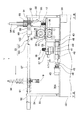
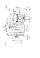
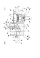
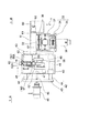
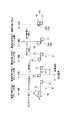
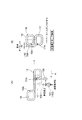
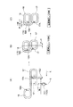
図1は上記実施形態の連結コイル形成装置10を示すブロック図、図2は上記連結コイル形成装置10により形成される連結コイル16の全体斜視図、図3は連結コイル形成装置10を示す全体平面図、図4は図3におけるIV矢視図で連結コイル形成装置10を示す全体側面図、図5は図4におけるV矢視図で連結コイル形成装置10の主に搬送ユニットを示す全体平面図である。
FIG. 1 is a block diagram showing the connecting
本実施形態の連結コイル形成装置10は、図3等に示すように、一方の端部に形成された角筒状の第1コイル部17を有する長尺素材である平角線Wを、その他方の端部から導入すると共にその他方の端部に、当該端部を順次巻線加工して角筒状の第2コイル部18を形成し、かつ当該第2コイル部18と上記第1コイル部17とを並列状態に配置して前記連結コイル16(図2参照)を形成するものである。
As shown in FIG. 3 and the like, the connecting
図1にも示すように、上記連結コイル形成装置10は、前記第2コイル部18を形成するコイル巻線機55と、このコイル巻線機55を装備すると共に当該コイル巻線機55による巻線加工を可能とするよう前記平角線Wの1辺分ずつコイル巻線機55を往復移動させるヘッド送りユニット40と、ヘッド送りユニット40を駆動させるユニット駆動手段であるモータ45と、上記コイル巻線機55、ヘッド送りユニット40およびモータ45を駆動制御する駆動制御手段20と、を備えて構成されている。
As shown in FIG. 1, the connecting
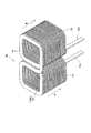
まず、図2に基づいて、連結コイル形成装置10により形成される連結コイル16の説明をする。
連結コイル16は、長尺素材である1本の平角線Wの長さ方向一方と他方との端部に、それぞれ角巻して当該角巻部が角筒状に積層された状態に形成された第1コイル部17および第2コイル部18を備えて形成されている。
また、平角線Wは、断面矩形形状の導線に被膜が施されたものである。
First, the connecting
The connecting
Moreover, the flat wire W is obtained by coating a conducting wire having a rectangular cross section.
本実施形態の連結コイル形成装置10により形成される連結コイル16は、予め一方の端部に第1コイル部17が形成されると共に、その他方の端部に、予め、第2コイル部18を角巻きするのに必要な長さの平角線Wを他方の端部から導入し、その他方の端部に第2コイル部18を角巻きして形成した2連の連結コイル16である。
このため、第2コイル部18の角巻き工程中の各辺を形成するときの線材送り誤差の累積が、第1コイル部17の軸心と第2コイル部18の軸心との距離のバラツキとなって現れるおそれがある。
In the connecting
For this reason, the accumulation of the wire rod feeding error when forming each side during the square winding process of the
この第1コイル部17および第2コイル部18間には、当該各コイル部17,18を同一面上で連結する連結部19が設けられ、この連結部19は、各コイル部17,18相互間に位置する前記平角線Wで形成されている。そして、第1コイル部17および第2コイル部18は、互いに並列状態に配置され、かつ相互に同じ巻き方向に形成されている。
ここで、角巻きとは、コイルを角筒状に巻くことをいい、コイルを丸型に巻く丸巻きと対比されている。
A connecting
Here, square winding refers to winding a coil in a rectangular tube shape, and is contrasted with round winding in which a coil is wound in a round shape.
連結コイル16の第1コイル部17と第2コイル部18とのそれぞれの端部はリード部17A,18Aとなっており、これらのリード部17A,18Aは、第2コイル巻線工程の最終段階で2個のコイル17,18が接近した時に、互いのコイル部17,18と干渉しないように、各巻線工程が始まる直前に、図示のように、平角線Wの厚さ方向(各コイル部17,18の積層方向)に対して略90°曲げられるようになっている。
The end portions of the
各リード部17A,18Aの被膜は剥離され、導体が剥き出しになっており、図示しない圧着端子等を設けて他の電気部品等と接続されるようになっている。
なお、2つのコイル部17,18のリード部17A,18Aは、各コイル部17,18の軸方向の同じ側にあるから、リード部17A,18Aの先端部に、図示しない端子を取り付ける場合にも、端子の位置を揃えることが可能である。
The film of each
In addition, since the
そして、第1コイル部17と第2コイル部18との連結部19近傍の第2コイル部18側の一辺の部分(以下、オフセット部分という)19Aは、連結コイル16を成形したときに発生する第1コイル部17の軸心と、第2コイル部18の軸心との距離のバラツキをなくすために、調整用としてのオフセット量を持たせ、かつ第2コイル部18の外形部より外側に突出させて巻線(以下、オフセット巻きという)されている。
そして、このオフセット部分19Aは第1コイル部17と第2コイル部18とを連結する連結部19を兼ねている。
A portion (hereinafter referred to as an offset portion) 19A on the
The offset
この連結コイル16は、その第2コイル部18の巻終り端部、つまりオフセット部分19Aにおいて、平角線Wを第2コイル部18側から、各コイル部17,18間の隙間長だけ突出させて略90度巻線加工し、第1コイル部17の積層方向(図2中に矢印Aで示す)と同一方向(図2中に矢印Bで示す)に、第2コイル部18が積0層されるように、かつ、第1コイル部17の巻き方向と同方向に角巻きされることにより、第2コイル部18の巻き終わり時点で、第1コイル部17と第2コイル部18とが、前記連結部19を介して、連続して並列状態に形成される。
The connecting
また、連結部19が第1コイル部17と第2コイル部18とが同じ向きに形成されているので、連結コイル16を、図略のリアクトル用熱伝導性ケースに組み込んだとき、例えば熱伝導性ケースの底面に形成されている突起部等に干渉することがない。
このことは、連結部19のために、熱伝導性ケースの底面に形成される突起部の位置や形状を制限する必要がなくなり、これにより、設計の自由度が増す、という効果を得ることができるということである。
Moreover, since the
This eliminates the need for restricting the position and shape of the protrusion formed on the bottom surface of the heat conductive case for the connecting
さらに、第1コイル部17と第2コイル部18とには、図示しないが、略リング状のリアクトルコアの2箇所の直線部が挿入されるようになっており、そのため、第1コイル部17の軸心と第2コイル部18の軸心との距離は高い寸法精度が要求される。
本願では、前述のように、第1コイル部17と第2コイル部18との連結部19を形成する第2コイル部18側のオフセット部分19Aを、第1コイル部17と第2コイル部18間の距離を調整するための余長部分として設けた状態で角巻しているので、第1コイル部17と第2コイル部18との軸心間の距離を高精度で維持することができる。
Further, although not shown, two linear portions of a substantially ring-shaped reactor core are inserted into the
In the present application, as described above, the offset
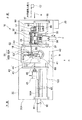
次に、図3〜図5に基づいて連結コイル形成装置10の全体構成を説明する。
連結コイル形成装置10は巻線機架台30を備え、この巻線機架台30の上面30A上には、前記線送り機32やヘッド送りユニット40等が配置されている。
Next, the whole structure of the connection
The connecting
図3〜図4に示すように、上記線送り機32は、上下に配置された一対のプーリ36(図4参照)と、これらのプーリ36をそれぞれ装着した一対の本体部37と、これらの本体部37に装備され上記一対のプーリ36を互いに反対方向に回転させる一対のモータ38とを備えて構成されている。
これにより、線送り機32では、一対のプーリ36で平角線導入側から供給された平角線Wの端部を挟み込み、一対のプーリ36をそれぞれ逆方向に回転させて、平角線Wを次に送り込むことができる。
As shown in FIGS. 3 to 4, the
Thus, in the
この線送り機32では、本体部37および平角線Wを挟み込む前記一対のプーリ36ともども、平角線Wから離れる方向の平角線Wの送り方向Kと直交するY軸方向に退避したとき、導入された平角線Wの一方の端部に形成されている前記第1コイル部17の通過を許容できる構造となっている。
In this
すなわち、図6〜図9にも示すように、一対の本体部37およびプーリ36は、枠体33に取り付けられた左右のスライド軸34に沿ってY軸方向にスライド自在となっている。枠体33は、Y軸方向に間隔をおいて配置された支持部材35と、これらの支持部材35の両端に架けわたされた上記スライド軸34を備えて構成されている。
That is, as shown in FIGS. 6 to 9, the pair of
また、線送り機32には、取り付け部材61を介して第1のコイル受け部材60が装備されている。この第1のコイル受け部材60は、前記コイル巻線機55により平角線Wの他端部に前記第2コイル部18が巻線加工されるに連れ、当該第2コイル部18に接近する第1コイル部17が、前記平角線導入側から巻線機架台31側に導入されたとき、上記第1コイル部17を含む平角線Wを受けるものである。
なお、線送り機32は前述のようにY軸方向に移動可能となっているので、線送り機32に一体的に装備された第1のコイル受け部材60も、線送り機32がY軸方向に退避するとき同時に移動することになる。
Further, the
Since the
前記巻線機架台31において線送り機32の、平角線Wの送り方向Kの下流側には、前記ヘッド送りユニット40が配置されている。
このヘッド送りユニット40は、前記線送り機32がY軸方向に退避した場合に、当該線送り機32に代わって平角線Wを下流側に送り込み、巻線加工の実行を補助するために設けられているものである。
The
The
ヘッド送りユニット40は、平角線Wの送り方向Kに沿って往復スライド自在となった板状の本体部41と、この本体部41を支持する枠体42とを備えて構成されている。枠体42は、平角線Wの送り方向に間隔をおいて配置された支持部材43と、これらの支持部材43の両端間に架けわたされ、上記本体部41をスライド自在とするスライド軸44とを備えて構成されている。
The
また、枠体42を挟んで前記線送り機32の反対側には、本体部41をスライド駆動させるユニット駆動手段としてのパルスモータ45が配置されている。このモータ45の主軸はボールネジ46に連結されている。
本体部41の裏面には、図6等に示すように、上記ボールネジ46と螺合するナット47と、スライド軸44をガイドするガイド部材48とが設けられている。これにより、パルスモータ45を駆動させるとボールネジ46とナット47との螺合により、本体部41がスライド軸44に沿って支持部材43間でスライドできるようになっている。
Further, a
As shown in FIG. 6 and the like, a
前記コイル巻線機55は、図6〜図9に詳細を示すように、上記ヘッド送りユニット40の本体部41の上面に設置されている。
コイル巻線機55は、前記線送り機32、またはヘッド送りユニット40による1辺ずつの送りにより、平角線Wの他端部に、当該他端部を順次角巻して角筒状の前記第2コイル部18を形成するものである。
The
The
なお、第2コイル部18の巻線工程の最終段階で、2個のコイル部17,18が接近した時に互いのコイル部17,18に干渉しないように、第2コイル部18の前記リード部18Aは、当該第2コイル部18の巻線工程が始まる前に、図示しない機構等により、平角線Wの表面、つまり第2コイル部18の積層方向に対して直交する方向に90°曲げられている(図2参照)。
ここで、第1コイル部17の前記リード部17Aも、前記連結コイル形成装置10に導入されるときは、上記第2コイル部18と同様、すでに90°曲げられている(図2参照)。
In addition, when the two
Here, when the
前記コイル巻線機55は、平角線Wの90度巻線加工を実行する巻線部56を備えている。この巻線部56は、丸軸状の固定治具56Aと角棒状の巻治具56Bとで構成され、これらの固定治具56Aおよび巻治具56Bは、ヘッド本体部57に設けられている。
固定治具56Aは、送られてくる平角線Wをガイドすると共に、その平角線Wの巻線加工時に幅方向一端側側面を固定するものである。
The
The fixing
また、巻治具56Bは、平角線Wの巻線加工時に幅方向他端側の側面を固定治具56A側に押圧すると共に、平角線Wの巻線加工方向に略90度回動できるような構成となっている。また、角棒状の巻治具56Bは、その先端が平角線Wの幅方向他端側側面と当接した状態で回転するようになっている。
Further, the winding
ヘッド本体部57等は基台58に設けられ、また、この基台58には、図略の駆動モータが設けられている。したがって、巻治具56Bの90度巻線加工のための回動は、図略の駆動モータを駆動させて、固定治具56Aを中心としてヘッド本体部57等を基台58に対して回動させて行われる。
The head
また、ヘッド送りユニット40の本体部41の上面には第2のコイル受け部材62が設けられている。この第2のコイル受け部材62は、図6等に示すように、前記第1のコイル受け部材60上に載置されている平角線Wを、当該第1のコイル受け部材60から引き継いで導入するものである。
A second
さらに、第2のコイル受け部材62には第2コイル部18を受ける上面ガイド62Aが設けられている。この上面ガイド62Aは、シリンダ63によってY軸方向にスライド可能となっており、また、シリンダ63は、第2のコイル受け部材62の側面に設けられている。
上面ガイド62Aは、コイル巻線機55による第2コイル部18の巻線加工が終了し、第1コイル部17との間で並列状の連結コイル16が完成した後、その連結コイル16を第2のコイル受け部材62から、平角線Wの送り方向先側に送り出して、あるいは固定治具56Aの上方に抜き出して取り出すとき、第2のコイル受け部材62および固定治具56Aのどこにも干渉せずに取り出せるように、連結コイル16の並列方向、かつ線送り機32の退避方向とは逆方向にスライドできるようになっている。
Further, the second
After the winding of the
図3〜図5に示すように、巻線機架台31の上面31Aには、巻線機架台31における平角線Wの送り方向Kの両端にわたってコイル搬出ユニット84が設けられている。
このコイル搬出ユニット84は、巻線機架台31の平角線Wの送り方向Kの両端のそれぞれ2箇所に所定間隔をおいて立設された2本の柱状部材85と、これらの柱状部材85間に架けわたされたチャックユニット用ガイド部材87とを備えて構成されている。
As shown in FIGS. 3 to 5, a coil carry-out
The coil carry-out
チャックユニット用ガイド部材87にはチャックユニット88が係合し、このチャックユニット88は、平角線Wの送り方向Kに沿ってスライド可能となっている。
チャックユニット88は、矩形形状の箱状に形成されたスライド本体89を備えており、このスライド本体89の厚さ方向(上下方向)側面に、上記2本のチャックユニット用ガイド部材87に係合する水平な貫通穴89Aがあけられている。また、スライド本体89の側面で2本のチャックユニット用ガイド部材87の中間位置には、貫通穴89Aと平行に、かつスライド本体89の長さ方向略中央部に達するチャック移動シリンダ90のロッド90A用の穴89Bがあけられている。
A
The
上記チャック移動シリンダ90のロッド90Aの先端はスライド本体89の上記中央部の図示しない固定部に係止されている。また、上記チャック移動シリンダ90は、柱状部材85において平角線Wの送り方向Kの流れの最下流側に取り付けられている。
したがって、チャック移動シリンダ90を駆動させ、そのロッド90Aを前後移動させることにより、スライド本体89がチャックユニット用ガイド部材87に沿って前後方向にスライドすることになる。
The tip of the
Therefore, by driving the
スライド本体89には、前記連結コイル16を把持するチャック機構91が設けられている。すなわち、チャック機構91は、図4,5に示すように、支持ブロック93を介してスライド本体89に取り付けられ、この支持ブロック93は、スライド本体89の送り方向と直交する方向の一方の側面に上方に突起して設けられている。
The
チャック機構91は、上下移動用シリンダ94に連結されている。
すなわち、スライド本体89の上面には支持ブロック93が設けられ、この支持ブロック93には、上下方向に貫通するシリンダ用穴と、チャック機構91の上下移動をガイドするガイド軸95用の貫通穴とがあけられている。
The
That is, a
チャック機構91は、支持ブロック93の下方に位置しており、支持ブロック93に吊るされた状態となって設けられている。そして、チャック機構91の下端には連結部96が設けられ、この連結部96の上面に上記上下移動用シリンダ94のロッドが連結され、また、連結部96においてロッドの両側に上記ガイド軸95が立設されている。
さらに、連結部96には、下方に延びてチャック部92が設けられている。チャック部92は、周知の構造により開閉可能となっている。
The
Further, the connecting
したがって、上下移動用シリンダ94を駆動させると、そのロッドが前進あるいは後退することにより、チャック機構91が下降、あるいは上昇する。そして、チャック機構91が所定位置まで下降したとき、チャック部92が閉じて、所定位置に送られてきた前記第1コイル部17を把持できるようになっている。
Therefore, when the
以上のようなコイル搬出ユニット84には、図4,5に示すように、スライド本体89の幅方向両側面に、当該スライド本体89の移動をストップする移動ストッパ機構98が設けられている。
この移動ストッパ機構98は、スライド本体89の幅方向両側面に取り付けられたシリンダ98と、このシリンダ98のロッド先端に設けられた図略のストッパ部材とで構成されている。そして、上記ストッパ部材がロッドの前後動、つまりガイド部材87の径方向移動により前記ガイド部材87と接触・離隔可能となり、接近して当接することでガイド部材87を押圧し、これによりスライド本体89、ひいてはチャック機構91の移動をストップさせるようになっている。
As shown in FIGS. 4 and 5, the coil carry-out
The moving
前記対向配置された柱状部材85間のガイド部材87の反対側にはセンサ取り付け軸100が架けわたされている。このセンサ取り付け軸100の長さ方向所定位置には、コイル位置を測定するコイル位置測定センサ101が取り付けられており、このコイル位置測定センサ101は、第2コイル部18の巻線加工に連れて当該第2コイル部18側に接近する前記第1コイル部17の位置を測定するものである。この測定センサ101としては、例えば透過型フォトセンサが用いられている。
A
これに対して、前記スライド本体89の上面、かつ前記支持ブロック93の突出部の対角線上には、上記センサ101と対応するセンサドグ102が取り付けられている。そして、センサ101とセンサドグ102とで前記コイル部位置測定手段22が構成されている。
そして、スライド本体89が平角線Wの送り方向に沿って移動する際、センサドグ102の移動を上記センサ101が検出し、その信号を前記主制御部21の演算制御部24に送信するようになっている。
On the other hand, a
When the
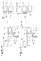
以上のような構成のコイル搬出ユニット84のチャックユニット88と、前記線送り機32と、前記ヘッド送りユニット40との相互の関連を図6〜図9に基づいて説明する。
図6に示すように、前記コイル巻線機55と前記線送り機32の連動により第2コイル部18の巻線が進むに連れて、平角線材Wの一方の端部に形成されている第1コイル部17は線送り機32に接近してくる。
The mutual relationship among the
As shown in FIG. 6, as the winding of the
第1コイル部17が線送り機32と干渉する直前の所定位置に到着すると、その位置で待機しているコイル搬出ユニット84のチャック機構91を下降させると共に、最下点に達したとき、そのチャック部92を閉じて第1コイル部17を把持させる。このとき、移動ストッパ機構98のストッパ機能は作動していない状態で、かつチャック移動シリンダ90はピストンのいずれの側にも駆動エアー圧が供給されていない摺動フリーの状態である。
When the
次いで、図7に示すように、線送り機32の一対のプーリ36による平角線Wのクランプを解除すると共に、線送り機32の本体部37およびプーリ36をY軸方向に移動させて平角線Wから離れる方向に退避させる。
Next, as shown in FIG. 7, the clamp of the rectangular wire W by the pair of
その後、固定治具56Aに直結した図略のシリンダによって、固定治具56Aを下方に駆動することで平角線Wをクランプし、かつ固定治具56Aで引掛けた状態でヘッド送りユニット40のモータ45を駆動させ、ボールネジ46とナット47との作用により本体部41を送り平角線Wを引出す。このとき、チャック機構91は動きがフリーであり、移動ストッパ機構98のストッパ機能は作動していない状態である。
Thereafter, the rectangular wire W is clamped by driving the fixing
次に、図8に示すように、コイル巻線機55により次の辺の巻線加工をするために、平角線Wを引き出した後、固定治具56Aによるクランプを開放して、ヘッド送りユニット40を一辺の長さ分戻す。このとき、第1コイル部17を把持した状態でチャック機構91の移動がフリーだと、ヘッド送りユニット40の戻りに連れ動きするため、移動ストッパ機構98のストッパ機能を作動させる。つまり、シリンダ99を駆動させ、そのロッド先端のパッドをガイド部材87に押し付けてチャック機構91をストップさせる。巻線時には、ストッパ機構98を解除してチャック機構91を再び移動フリーの状態とする。
Next, as shown in FIG. 8, in order to perform winding processing of the next side by the
図6〜図8の動作を繰り返し、第1コイル部17と第2コイル部18とが、図9に示すように、並列状態に配設した連結コイル16が完成したら、上面ガイド62Aを連結コイル16が取外し可能な位置までスライドさせた後に、図4に示すように、コイル巻線機55の位置から、第1コイル部17を把持した状態でチャック機構91を上昇させ、スライド本体89を移動させて連結コイル16を完成連結コイル搬出位置Bまで搬送する。
スライド本体89は、その後、平角線導入側A(図3参照)の初期位置に戻り、そこで待機するようになっている。
When the operation of FIGS. 6 to 8 is repeated and the connecting
Thereafter, the slide
図1に戻って、前記連結コイル形成装置10には、前記駆動制御手段20が設けられている。
この駆動制御手段20は、前記コイル巻線機55、ヘッド送りユニット40およびモータ45の各動作を制御する主制御部21を含んで構成されている。
Returning to FIG. 1, the connecting
The drive control means 20 includes a
主制御部21には、コイル部位置測定手段22とメモリ手段23とが接続されている。
また、主制御部21には各種情報を入力するための入力手段27が接続されている。
コイル部位置測定手段22は、巻線加工の進行と共に接近する前記第1コイル部17の予め設定された測定基準位置S(図11,13等参照)からの距離を、第2コイル部18の最後の巻線加工の3ターン前で測定するものである。
なお、本実施形態では、第2コイル部18の最後の巻線加工の3ターン前で測定しているが、3ターン以上手前で測定しても位置補正は可能である。ただし、位置測定後に発生する巻線加工による誤差の累積ということについては、3ターン前測定が一番有利である。
Coil portion position measuring means 22 and memory means 23 are connected to the
The
The coil part position measuring means 22 determines the distance from the preset measurement reference position S (see FIGS. 11 and 13, etc.) of the
In the present embodiment, the measurement is performed 3 turns before the last winding of the
メモリ手段23には、予め設定されている上記測定基準位置Sから3ターン前での第1コイル部17までの基準距離が記憶されている。
また、このメモリ手段23には、上記基準距離の他、主制御部21による制御に必要な各種の情報、例えば、予め設定された第1、第2コイル部17,18間の隙間の基準寸法(設定寸法)、平角線Wの幅および厚さ寸法、矩形形状の角筒状に巻き上げる積層段数、矩形角筒形状の長辺寸法、および短辺寸法、第1、2コイル部17,18を形成するのに必要な平角線Wの全長寸法、等の情報も記憶されている。
The memory means 23 stores a reference distance from the measurement reference position S set in advance to the
In addition to the above-mentioned reference distance, the memory means 23 has various information necessary for control by the
また、主制御部21には、測定された距離と基準距離とを比較演算してその差をオフセット量として求めると共に、そのオフセット量を加味して第2コイル部18の最後より2ターン手前の巻線加工位置を設定する演算制御部24が設けられている。
In addition, the
そして、この演算制御部24が、パルスモータ45を介してヘッド送りユニット40およびコイル巻線機55による1ターン手前の位置、および最後の巻線加工位置での巻線加工を制御する巻線加工制御機能を有し、これにより第2コイル部18を形成すると共に当該第2コイル部18を第1コイル部17に並列状に設定できるようになっている。
Then, the
演算制御部24では、上記最後の巻線より1ターン手前の巻線加工のためにオフセット寸法を加味した寸法で1辺分を送り出し、また、最終巻線加工のために各コイル部17,18の間隔を加味した寸法で1辺分を送り出す際、前述のように、各寸法に相当するようなパルス数を、レジスタ30を介してモータ45に発するようになっている。
The
主制御部21には、当該コイル巻線機55が平角線Wの巻線加工を行う際、実際に折り返した回数をカウントする巻数カウント部25が設けられている。この巻数カウント部25でカウントされた巻線回数は、主制御部21に設けられている測定時期演算判定部28に常時送出されている。
また、主制御部21は、予め設定されている第2コイル部18の基準の総巻線回数が記憶された巻線加工用回数記憶部26を備えている。
The
Further, the
そして、巻線加工用回数記憶部26に記憶されている基準の巻線回数と、巻数カウント部25でカウントされた実際の巻線回数とが、上記測定時期演算判定部28により、常時、比較演算され、前記第2コイル部18の最後の巻線加工の3ターン前が判断されるようになっている。
また、測定時期演算判定部28では、第2コイル部18の最後の巻線加工の3ターン前であることの判断を行なった後、測定開始時期の指令を前記コイル部位置測定手段22に発する機能を有している。
Then, the reference winding number stored in the winding processing
In addition, the measurement timing
主制御部21には、コイル巻線機用駆動制御部29が設けられ、この駆動制御部29により前記コイル巻線機55が駆動制御されるようになっている。
すなわち、コイル巻線機55における巻線部56の固定治具56Aと巻治具56Bとによる巻線のタイミング、戻りのタイミング等が駆動制御される。
The
In other words, the timing of winding and the timing of return by the fixing
また、主制御部21と前記線送り機32、コイル搬出ユニット84、およびチャックユニット88とは接続されており、線送り機32等を主制御部21により駆動制御することができる。
Further, the
主制御部21と線送り機32との間では、入力手段27からの指令に基づいて、コイル巻線機55で平角線Wの他端部に第2コイル部18を形成するために当該コイル巻線機55に平角線Wを送り出し、あるいは、必要に応じて平角線Wから離れる方向に退避させる等の制御が行われる。
すなわち、第2コイル部18の巻線加工が進むに連れ第2コイル部18側に接近する第1コイル部17が測定開始位置に到達したとき、線送り機32をY軸方向に退避させるタイミング、および退避速度等の制御が行われる。
In order to form the
That is, when the
主制御部21とヘッド送りユニット40との間では、前述のように、第2コイル部18の最後の巻線加工の3ターン前、最後の巻線加工の1ターン手前でのパルス信号を送って駆動させると共に、通常では、入力手段27からの指令に基づいて、線送り機32による平角線Wの送り作用が及ばなくなった場合に、ヘッド本体部41を矢印M方向(図3等参照)に往復移動させることで、平角線Wを移送させる制御等が行われる。
As described above, a pulse signal is sent between the
主制御部21とコイル搬出ユニット84との間では、入力手段27からの指令に基づいて、一端部に第1コイル部17が形成された平角線Wが形成途中の第2コイル部18に接近する所定位置で、第1コイル部17を把持すると共に、ヘッド送りユニット40およびコイル巻線機55による第2コイル部18の巻線加工に追従し、また、連結コイル16の完成後に、その連結コイル16を所定位置に搬出させる等の制御が行われる。
Between the
次に、図10のフローチャート、および図11の巻線加工ごとに変化する第1コイル部17、第2コイル部18の形状等の模式図に基づいて、かつ図12〜21を参照しながら、前記連結コイル形成装置10による連結コイル形成制御方法を説明する。
本連結コイル形成制御方法は、一方の端部に形成された角筒状の第1コイル部17を有する平角線を他方の端部から導入すると共に、その端部を順次1辺ずつ巻線加工して角筒状の第2コイル部18を形成し、かつ当該第2コイル部18と第1コイル部17とを並列状態に配置し連結コイル16を形成する方法である。
Next, based on the flowchart of FIG. 10 and schematic diagrams such as the shapes of the
This connected coil formation control method introduces a rectangular wire having a rectangular tube-shaped
まず、図12に基づいて第1コイル部17と第2コイル部18の相対位置関係について説明する。
First, the relative positional relationship between the
各コイル部17,18の相対位置図におけるコイルピッチXは、予め設定されたコイルスキマL2の値に応じて、第2コイル部18の巻線工程最終ターンで形成される。
一方、コイルズレYは最終巻線工程の1ターン手前の巻線動作においてゼロになるよう、すなわち第1コイル部17と第2コイル部18がズレなく並列となるように位置補正される。このコイルズレYは、第2コイル部18の巻線工程における平角線Wの送り誤差等の累積により生じるものである。
The coil pitch X in the relative position diagram of each of the
On the other hand, the position of the coil deviation Y is corrected so that it becomes zero in the winding operation one turn before the final winding process, that is, the
本連結コイル形成装置10による連結コイル形成制御方法では、第2コイル部18の巻線加工中のある時点で任意の基準位置(前記測定基準位置S)から第1コイル部17の距離を測定し、この距離データに応じて調整代であるオフセット部を形成することで、第2コイル部18の巻線加工を行う時点までの累積誤差を解消するものである。
In the coupled coil formation control method by the coupled
連結コイル形成制御方法は、まず、平角線Wの一方の端部に第1コイル部17が形成されている状態で、ヘッド送りユニット40上に装備されているコイル巻線機55に導入され、このコイル巻線機55により、第2コイル部18の巻線加工が開始される。
第2コイル部18の巻線加工が進むに連れ、図13に示すように、第1コイル部17は線送り方向Kに沿って移動し、第2コイル部18側に接近する。
前記図10のフローチャートは、この状態からスタートしている。
The connected coil formation control method is first introduced into the
As the winding process of the
The flowchart of FIG. 10 starts from this state.
第1コイル部17が第2コイル部18側に接近し、当該第2コイル部18の最後の巻線加工より3ターン手前の巻線加工が終了して2ターン手前の巻線加工のために平角線材の送り出しを開始したとき、第1コイル部17の位置測定がスタートし、図10に示すように、第1の工程として、ステップ(ST)1では、前記コイル部位置測定手段22を構成するコイル測定センサ101とセンサドグ102とにより、第1コイル部17の位置を測定するコイル位置測定が行なわれる。
The
ここで、コイル位置測定の開始は、前述のように、前記巻数カウント部25でカウントしたコイル巻線機55の巻数と、巻線加工用回数記憶部26に予め設定されている基準の巻線回数とを比較・演算し、第2コイル部18の最後の巻線加工の3ターン前の巻線動作が終了したことを、測定時期演算判定部28で判断した後、その情報を、測定時期演算判定部28からコイル部位置測定手段22に発信することにより行なわれる。
Here, the coil position measurement is started with the number of turns of the
ステップ(ST)2では、測定パルスPと基準パルスPの差が、ΔP=P−P基準として演算される。
この演算は、前記演算制御部24により、メモリ手段23に記憶されている基準位置からの第1コイル部17までの距離と、コイル部位置測定手段22により測定された距離とを基に行われる。
In step (ST) 2, the difference between the measurement pulse P and the reference pulse P is calculated as ΔP = P−P reference.
This calculation is performed by the
ステップ(ST)3では、最後の巻線加工1ターン手前のヘッド本体部57の送り補正パルスが、Pヘッド送り補正=ΔP/2として演算され、これにより、オフセット量が決定される。
この演算も、上記演算制御部24により行われる。
In step (ST) 3, the feed correction pulse of the head
This calculation is also performed by the
ステップ(ST)4では、次回巻線時の第2コイル用リード長の補正パルスが、
Pリード長補正=k×ΔP(k:設定パラメータ)として演算される。
この演算も、上記演算制御部24により行われる。
なお、第1コイル部17と第2コイル部18のズレYは、巻線動作時の機械的累積誤差以外に、平角線Wの硬さや線材ボビンに巻かれた線材の巻きグセの影響も受けるものと考えられ、また、これらの平角線Wの品質のバラツキは、連続的にゆるやかに変化するものと考えられる。
そういった品質のばらつきによる影響も、コイル位置の測定結果をフィードバックさせることで、ある程度低い範囲に抑えようとする目的で、次回の巻線の第2コイル用リード線の設定長さに対してk×ΔPという補正量を加減することもできるようにしたものである。
そして、上記式において、kはいわゆる重みの乗数で、k=1であれば、コイル位置の長短が次回巻線の第2コイルリード長さの長短にそのまま反映され、1以下であればそれがより緩やかになるといった、実際の稼動を通して求められる数値である。
In step (ST) 4, the correction pulse for the lead length for the second coil at the next winding time is
P lead length correction = k × ΔP (k: setting parameter)
This calculation is also performed by the
In addition, the deviation Y between the
For the purpose of suppressing the influence of such quality variations to a certain low range by feeding back the measurement result of the coil position, it is k × with respect to the set length of the second coil lead wire of the next winding. The correction amount ΔP can be adjusted.
In the above equation, k is a so-called weight multiplier. If k = 1, the length of the coil position is directly reflected in the length of the second coil lead length of the next winding. It is a numerical value required through actual operation, such as becoming more gradual.
ステップ(ST)5では、演算された巻線加工ヘッド送り補正パルスおよび演算された第2コイル用リード長の補正パルスが、演算制御部24から制御部レジスタ30に転送される。
In step (ST) 5, the calculated winding machining head feed correction pulse and the calculated second coil lead length correction pulse are transferred from the
ステップ(ST)6では、巻線が最後の巻線加工1ターン手前になったか否かの判断が行なわれる。最後の巻線加工1ターン手前になったことが確認できたら(YES)、次のステップ(ST)7に進み、最後の巻線加工1ターン手前になったことの確認ができなかったら(NO)、ステップ(ST)6の前に戻り、最後の巻線加工1ターン手前になるまで繰り返す。 In step (ST) 6, it is determined whether or not the winding is one turn before the final winding processing. If it can be confirmed that the last winding process is one turn (YES), the process proceeds to the next step (ST) 7 and if it is not confirmed that the last winding process is one turn (NO) (NO) ), Return to step (ST) 6 and repeat until one turn before the last winding process.
ステップ(ST)7では、コイル位置補正用の送りパルスを、P位置補正送り=P辺送り+Pヘッド送り補正として演算する。これにより連結部のオフセット量が決定される。
そして、上記ステップ(ST)2からステップ(ST)7までが、連結コイル形成制御方法における第2の工程となる。
In step (ST) 7, a feed pulse for coil position correction is calculated as P position correction feed = P side feed + P head feed correction. Thereby, the offset amount of the connecting portion is determined.
Steps (ST) 2 to (ST) 7 are the second step in the connected coil formation control method.
ステップ(ST)8では、演算値に基づく最後の巻線加工1ターン手前の加工位置が設定される。 In step (ST) 8, the machining position one turn before the last winding machining based on the calculated value is set.
第3の工程として、ステップ(ST)9では、演算された巻線加工ヘッド送り補正パルスの値、つまりP位置補正送りの値で線材(平角線)を送り、最後の巻線加工1ターン手前の巻線加工を行い、第1コイル部17の位置を補正する。
As a third step, in step (ST) 9, a wire rod (flat wire) is sent at the calculated value of the winding machining head feed correction pulse, that is, the value of the P position correction feed, and one turn before the last winding machining. The winding process is performed to correct the position of the
第4の工程として、ステップ(ST)10では、第1コイル部17と第2コイル部18との隙間を考慮した最後の巻線加工が行なわれ、連結コイルが完成する。
As a fourth step, in step (ST) 10, the final winding processing is performed in consideration of the gap between the
ここで、前記第1の工程の前工程として、第2コイル巻線途中での第2コイル部18に対する第1コイル部17の位置を監視する第1コイル位置監視工程が設けられている。
すなわち、この第1コイル位置監視工程では、パルスモータ45の稼動と共に出力される計測用パルスを、パルスモータ45の駆動開始から予め取り付けられたコイル位置測定センサ101が第1コイル部17側に取付けられたセンサドグ102を検知するまでカウントすることによって第1コイル部17の位置を監視するようになっている。
Here, a first coil position monitoring step for monitoring the position of the
That is, in this first coil position monitoring step, a coil
次に、第1コイル部17の接近と第2コイル部18の形状の変化とを、図11に基づいて詳細に説明する。
第2コイル部18は四角筒形状となっているので、1ターンは順次90度ずつ折曲げる際の最初の巻線加工であり、つまり1/4巻きである。
したがって、上記最後の巻線加工3ターン前の巻線動作が終了したときは、1つの角筒を形成するための最初の1/4巻線加工が終了したときである。
Next, the approach of the
Since the
Therefore, when the winding operation three turns before the last winding processing is completed, the first quarter winding processing for forming one rectangular tube is completed.
また、最後の巻線より3ターン手前の巻線動作が終了し(コイル姿勢は図11中の1/4巻)、次回巻線動作のために平角線Wが通常の送り寸法で送られるときに前記コイル部位置測定が行われる。
コイル部位置測定後の巻線動作により最後の巻線より2ターン手前の巻線(図11中2/4巻線加工)が終了する。次いで最後の巻線加工1ターン手前では、最後の巻線加工における3回目の巻線加工、つまり3/4巻線加工が実行される。この3/4巻線加工は図12におけるコイルのY方向のずれを前記コイル部位置測定のデータに基いて補正する巻線動作である。
ここで、最後の巻線加工2ターン前までは、1ターンごとに通常の送り寸法BP(パルス)送りと、AP(パルス)送りとが交互に繰り返されている。そして、BP送りは、前記第1コイル部17の長辺寸法をパルス数で表した寸法、AP送りは、前記第1コイル部17の短辺寸法をパルス数で表した寸法である。
When the winding operation three turns before the last winding is completed (coil posture is 1/4 turn in FIG. 11), and the rectangular wire W is sent with the normal feed dimensions for the next winding operation. The coil part position is measured.
By the winding operation after the coil position measurement, the winding two turns before the last winding (2/4 winding processing in FIG. 11) is completed. Next, the third winding process in the last winding process, that is, the 3/4 winding process is executed one turn before the last winding process. This 3/4 winding process is a winding operation for correcting the deviation in the Y direction of the coil in FIG. 12 based on the data of the coil part position measurement.
Here, until two turns before the final winding, the normal feed dimension BP (pulse) feed and AP (pulse) feed are alternately repeated every turn. The BP feed is a dimension in which the long side dimension of the
最後の巻線加工2ターン前での巻線加工が終了した後、平角線Wは、最後の巻線加工2ターン前までの通常の辺送り寸法と、前述のようにオフセット量Fが加味された寸法とを加えた送り寸法で送られ、最後の巻線加工1ターン手前では、3回目の巻線加工、つまり3/4巻線加工が実行される。 After the winding process is completed two turns before the final winding process, the rectangular wire W is added with the normal edge feed dimension until the last two turns of the winding process and the offset amount F as described above. The third winding process, that is, 3/4 winding process, is performed one turn before the final winding process.
また、最後の巻線加工1ターン手前での巻線加工が終了した後、平角線Wは、通常の辺送り寸法と、前述のように予め設定されている第1コイル部17と第2コイル部18との間隔寸法を加えた送り寸法、すなわちBP+間隔寸法で送られ、4回目の巻線加工、つまり4/4巻線加工が実行されて第2コイル部18が完成する。
そして、第2コイル部18の完成と同時に、第1コイル部17と第2コイル部18とのズレがなく、かつ両コイル部17,18間の隙間が予め設定されている寸法と等しい寸法となった連結コイル16が完成する。
In addition, after the winding process is completed one turn before the final winding process, the flat wire W has a normal side feed dimension and the
At the same time as the completion of the
前述のように、第2コイル部18の巻線が進み、第1コイル部17が線送り方向Kに沿って移動し、第2コイル部18側に更に接近して、例えば巻線完了から3ターン以上(90度ずつ3回巻線)手前の状態になったら、コイル部位置測定手段22を構成するコイル測定センサ101とセンサドグ102により、第1コイル部17の位置が検出され、その情報が前記演算制御部24に伝送される。
As described above, the winding of the
測定センサ101は前述のようにセンサ取付け軸100の距離測定用の基準位置Sに固定されており、これに対応するセンサドグ102がスライド本体89に取付けられている。
このスライド本体89には第1コイル部17をチャックするチャック部92が設けられている。したがって、チャック部92に保持された第1コイル部17とセンサドグ102の位置関係は常に同じであるため、距離測定用基準位置Sからセンサドグ102までの距離を測定することで、第1コイル部17の位置情報を得ることができる。
この測定は、前述のように、最後の巻線加工3ターン手前で、次の曲げ工程のために平角線Wを送るときに行われる。
The
The
As described above, this measurement is performed when the flat wire W is sent for the next bending process three turns before the final winding process.
ヘッド送りユニット40により平角線Wを送るときには、前記パルスモータ45の図略の制御ドライバに駆動パルスが入力される。入力された駆動パルスによりモータが回転し、回転に同期してモータのエンコーダからパルスが出力される。
駆動パルス1個あたりのヘッド送りユニット40の移動量は、モータ部の減速比とボールネジ46のネジリード長さから算定され、駆動パルスとエンコーダ出力パルスは1:1に対応しているので、ヘッド送りユニット40が動作開始して、センサドグ102が測定センサ101に到達するまでに出力されるエンコーダパルス数をカウントすれば(図14の測定パルス数P)、これをセンサドグ102から距離測定用基準位置Sに固定された測定センサ101までの距離に換算することができる。
When the rectangular wire W is sent by the
The amount of movement of the
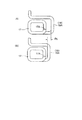
測定されたエンコーダパルス数に基づいて算定された測定センサ101(測定基準位置S)からセンサドグ102までの距離(リード)は、図15に示すように基準長さ、つまり適正距離である場合、図16に示すように適正距離より長い場合、図17に示すように適正距離より短い場合、という三様となる。
When the distance (lead) from the measurement sensor 101 (measurement reference position S) to the
図15(A)に示すように、センサ101とセンサドグ102間の距離が適正であるということは、第1コイル部17と第2コイル部18間の距離が、図15(B)に示すように、連結コイル16を形成するのに適正であるということである。すなわち、位置補正なしで巻線すると、図15(B)に示すように、両コイル部17,18は基準オフセットを伴って、前記コイルズレYがない状態、つまりコイルズレYがゼロの状態で連結コイル16が形成されるということである。
なお、図15(A)に示す両コイル部17,18の位置関係は、最後の巻線加工2ターン手前の状態である。
As shown in FIG. 15A, the appropriate distance between the
Note that the positional relationship between the
また、図16(A)に示すように、センサ101とセンサドグ102間の距離(リード)が長いということは、第1コイル部17と第2コイル部18間の距離が図15に示す適正値よりも長いということであり、図16(B)に示すように、位置補正なしで巻線したとき、両コイル部17,18間のコイルズレYが+側にズレルということである。
つまり、第1コイル部17が第2コイル部18に対して連結部19から離れる方向に位置しているということである。
そのため、図16(C)に示すように、上記ズレ分を+側にオフセットして(オフセット量を多くする位置補正)巻線することで、第1コイル部17と第2コイル部18間の距離、つまりコイルズレYを適正とすることができる。
Further, as shown in FIG. 16A, the long distance (lead) between the
That is, the
For this reason, as shown in FIG. 16C, the above-described misalignment is offset to the + side (position correction to increase the offset amount), and winding is performed, so that the
さらに、図17(A)に示すように、センサ101とセンサドグ102間の距離(リード)が短いということは、第1コイル部17と第2コイル部18間の距離が適正値よりも短いということであり、図17(B)に示すように、位置補正なしで巻線したとき、両コイル部17,18間のコイルズレYが−側にズレルということである。
つまり、第1コイル部17が第2コイル部18に対して連結部19に近づく方向に位置しているということである。
そのため、図17(C)に示すように、上記ズレ分を−側にオフセットして(オフセット量を少なくする位置補正)巻線することで、第1コイル部17と第2コイル部18間の距離、つまりコイルズレYを適正とすることができる。
Furthermore, as shown in FIG. 17A, the short distance (lead) between the
That is, the
For this reason, as shown in FIG. 17C, the above-described deviation is offset to the negative side (position correction to reduce the offset amount), and winding is performed, so that the
以上に説明したように、コイル間リード長がそれぞれ異なる場合に、連結コイルを形成するために、位置補正なしで(オフセット部は設ける)巻き終わったとき、それぞれの第1、第2コイル部17,18の相互位置はコイル間リード長の長短に応じてずれる。
As described above, when the inter-coil lead lengths are different from each other, when the winding is completed without position correction (offset portion is provided) in order to form a coupling coil, each of the first and
本方法は、コイル間リード長の長短に応じてオフセット長を変えることによって、巻線終了時のコイルズレYを補正するものである。そして、位置補正して巻き終わった図16(C)、図17(C)の連結コイル16が、それぞれの第1、第2コイル部17,18の相互位置のズレがない状態である。すなわち、コイルリードの長短はオフセット部のズレに表れていることを示している。
ここで、オフセット部を設けて、位置補正なしで相互位置のズレなく巻線された場合のコイル間リード長を適正長さと設定したのは、適正リード長さより短いコイル間リード長のコイルを補正巻線したときに、調整代であるオフセット部がコイルの内径内に表れないようにするためである。
This method corrects the coil misalignment Y at the end of winding by changing the offset length according to the length of the lead length between the coils. And the
Here, an offset part is provided, and the lead length between coils when winding is performed without misalignment without correcting the position is set to the appropriate length. The coil with a lead length shorter than the proper lead length is corrected. This is to prevent the offset portion, which is an adjustment allowance, from appearing within the inner diameter of the coil when it is wound.
図18において、1パルスPあたりの線送り量がLmmであれば、同図18(A)の場合の線送り補正量Fは次のような式(1)に基づいて求められる。
F=F0+(P1−P0)×L/2…(1)(F0は基準オフセット量)
この式(1)を図19(A)、(B)に基づいて補足説明すると、測定した2個の第1コイル部17において、オフセット部14のオフセット量が、図19(A)と図19(B)とでΔk違えば、その部分の線材長は2×Δkとなる。上記式(1)において(P1−P0)×Lを2で除すのはこの理由による。
In FIG. 18, if the line feed amount per pulse P is Lmm, the line feed correction amount F in the case of FIG. 18A is obtained based on the following equation (1).
F = F0 + (P1-P0) × L / 2 (1) (F0 is a reference offset amount)
This formula (1) will be supplementarily explained based on FIGS. 19A and 19B. In the two measured
線送り補正量Fが設定されたら、その補正量Fがオフセット寸法、つまり調整代とされる。そして、図20(A)に示すように、通常の送り寸法(ここでは、長辺寸法分)にオフセット寸法Fを加えた補正送り寸法L1が設定され、その補正送り寸法L1となるようなパルスPの値で線送りされる。
その後、この補正送り寸法L1で第1コイル部17を送った後、図20(B)に示すように、前記巻治具56Bを90度回動させて、平角線Wを巻線加工したとき、その部分の第2コイル部18の長辺寸法が上記オフセット寸法Fを加えた寸法となって現れるようになる。
When the line feed correction amount F is set, the correction amount F is used as an offset dimension, that is, an adjustment allowance. Then, as shown in FIG. 20A, a correction feed dimension L1 obtained by adding an offset dimension F to a normal feed dimension (long side dimension in this case) is set, and the pulse is set to the corrected feed dimension L1. The line is fed with the value of P.
Thereafter, after feeding the
次いで、図21(A)に示すように、予め設定されている図21(B)の両コイル部17,18間の隙間寸法L2を確保するために、通常の送り寸法、すなわち第1コイル部17の短辺の長さと隙間L2分の送り寸法L3で送り、その位置で、図21(B)に示すように、巻治具56Bを90度回動させるようになっており、これにより、最終角巻き工程として平角線Wを巻線加工したとき、両コイル部17,18間の隙間L2が正確に確保される。
なお、上記隙間寸法L2は、両コイル部17,18の軸心W1、W2間の寸法が、前記図12に示したコイルピッチXと一致しているとき必然的に決まる寸法であり、また、そのコイルピッチXは、予め特定されている。
Next, as shown in FIG. 21 (A), in order to ensure a predetermined gap dimension L2 between the
The gap dimension L2 is a dimension that is inevitably determined when the dimension between the axial centers W1 and W2 of the
以上のように、連結コイル16の第1コイル部17の軸心W1と第2コイル部18の軸心W2との寸法を予め設定(特定)されているコイルピッチXとすることにより、連結コイル16の第1コイル部17と第2コイル部18とに、略リング状のリアクトルコアの2箇所の直線部が確実に挿入されることになる。
As described above, the dimensions of the axial center W1 of the
ここで、前記線送り機32がY軸方向に移動して平角線Wから離れ、線送り機32による平角線Wの送り動作が停止されている際、特に、最後の巻線加工2ターン手前の状態から最終角巻きまでの第2コイル部18の巻き動作は、前記駆動制御手段20の指令によりモータ45を駆動させ、このモータ45の駆動により、前記ヘッド送りユニット40の本体部41を平角線送り方向Kに沿った方向に往復移動させ、それぞれの位置で、固定治具56Aを基点として巻治具56Bを90度回動させることで行われる。
Here, when the
すなわち、図20(A)に示すように、両コイル部17,18間の前記補正送り寸法L1となるように線送りパルス数Pが設定されたとき、ヘッド送りユニット40が固定治具56Aと巻治具56Bとを搭載するコイル巻線機55をS1の位置まで移動させることで平角線Wを補正寸法L1長さ送り出し、次いでS1の位置にあった仮想線で示す固定治具56Aと巻治具56Bとが、前述のようにヘッド本体部41が同じ補正寸法L1長さ戻ることにより、巻線加工位置S2まで移動する。
このとき、送り出した平角線Wがコイル巻線機55とともに戻らないようになっている。そして、巻線加工位置S2の位置で、図20(B)に示すように、90度の巻線加工が実施される。
なお、補正寸法L1は、図11に表示されているAP+オフセット寸法と同じである。
That is, as shown in FIG. 20A, when the number P of line feed pulses is set so that the correction feed dimension L1 between the
At this time, the fed rectangular wire W is prevented from returning together with the
The correction dimension L1 is the same as the AP + offset dimension displayed in FIG.
同様に、前記両コイル部17,18間の最後の巻線加工時には、図21(A)に示すように、S2の位置にあった仮想線で示す固定治具56Aと巻治具56Bとが、前述のようにヘッド送りユニット40が辺送り分移動することにより、前記寸法L3を得るために巻線加工位置S3まで移動する。そして、その位置で、図21(B)に示すように、90度の曲げが実施される。
なお、補正寸法L3は、図11に表示されているBP+隙間寸法と同じである。
Similarly, at the time of the final winding processing between the
The correction dimension L3 is the same as the BP + gap dimension displayed in FIG.
以上のような本第1実施形態によれば、次のような効果が得られる。
(1)第2コイル部18の巻線加工の進行と共に接近する第1コイル部17の位置が、第2コイル部18の最後の巻線加工の3ターン前で測定され、その距離が、演算制御部24により基準距離と比較演算され、第1コイル部17と第2コイル部18とのズレを調整するオフセット量Fとして求められる。そして、このオフセット量Fと第1コイル部17の一辺(長辺寸法)とをプラスした寸法で平角線Wを送り、第2コイル部18の最後の巻線加工1ターン手前の位置が設定され、その位置で巻線加工される。その結果、平角線Wの一方の端部に形成された角筒状の第1コイル部に対して平角線Wの他方の端部に角筒状の第2コイル部18をずれることなく並列状態に配設することができ、寸法精度の高い連結コイル16を得ることができる。
According to the first embodiment as described above, the following effects can be obtained.
(1) The position of the
(2)第1コイル部17と第2コイル部18とのズレがオフセット量Fとして演算され、そのオフセット量Fを加味した送り寸法で平角線Wを送る際、演算制御部24から出力されるパルス信号によりモータ45を駆動して行われるので、より高精度の送りが可能となり、寸法精度の高い連結コイル16を得ることができる。
(2) The deviation between the
(3)第1コイル部17と第2コイル部18とを連結する連結部19が両コイル部17,18に連続して設けられているので、連結部19を、溶接や折り返しを不要として、かつ容易に形成することができる。
(3) Since the connecting
(4)第1コイル部17までの距離を測定したとき、固定されている測定センサ101から第1コイル部17と共に移動するセンサドグ102までの距離(リード)が、適正距離である場合、適正距離より長い場合、適正距離より短い場合、という三様となって表れるが、適正距離の場合は、そのまま巻線加工すれば2つのコイル部17,18をズレなく並列状に配設することができ、また、適正距離より長い場合は、オフセット量Fを多くする位置補正で巻線加工し、適正距離より短い場合は、オフセット量Fを少なくする位置補正で巻線加工すればよく、これにより、測定結果に係わらず、2つのコイル部17,18をズレなく並列状に配設することができる。
(4) When the distance to the
(5)第1の工程(ST1)の前工程として、第2コイル巻線途中での第2コイル部18に対する第1コイル部17の位置を監視する第1コイル位置監視工程が設けられ、この第1コイル位置監視工程により、第2コイル部18の最後の巻線加工の3ターン前までの第1コイル部17の位置を常時、正確に把握できる。その結果、巻線動作時の機械的累積誤差以外に、平角線Wの硬さや線材ボビンに巻かれた線材の巻きグセの影響を受ける等の、平角線Wに品質のバラツキが生じていても、第1コイル部17の位置を正確に把握できるので、高精度の装置とすることができる。
(5) As a pre-step of the first step (ST1), a first coil position monitoring step for monitoring the position of the
なお、本発明は前述の実施形態に限定されるものではなく、本発明の目的を達成できる範囲での変形、改良等は本発明に含まれるものである。
例えば、前記実施形態では、長尺素材として平角線Wを用い、この平角線Wの一端部と他短部とに、それぞれ第1コイル部17と第2コイル部18を形成するようにしたが、これに限らない。長尺素材として丸棒等の線材を用いてもよい。
It should be noted that the present invention is not limited to the above-described embodiments, and modifications, improvements, and the like within the scope that can achieve the object of the present invention are included in the present invention.
For example, in the embodiment, the rectangular wire W is used as the long material, and the
また、前記実施形態では、一端部に第1コイル部17が形成された平角線Wを、本実施形態の連結コイル形成装置10に導入するに際し、一端部に第1コイル部17を形成する巻線装置についてはどのような構成のものでもよい。
例えば、架台上に固定され平角線Wを送り出す線送り機と、上記架台上に固定され上記線送り機から送り出された平角線Wを順次角巻するコイル巻線機とを備えてコイル巻線装置を構成すると共に、このコイル巻線装置で平角線Wの一端部に第1コイル部17を形成した後、前記連結コイル形成装置10に導入するようにしてもよい。
Moreover, in the said embodiment, when introduce | transducing into the connection
For example, a coil feeder comprising: a wire feeder that is fixed on a pedestal and sends out a flat wire W; and a coil winding machine that is fixed on the cradle and sequentially turns the flat wire W sent from the wire feeder. The apparatus may be configured, and the
さらに、平角線Wの一端部に第1コイル部17を形成するコイル巻線装置を、第1の加工ラインと、第2の加工ラインと、これらの加工ライン間を往復移動しコイルを移載するコイル移載手段とを備えて構成すると共に、前記連結コイル形成装置10を第2の加工ラインの終端部に配設してもよい。この場合、第1の加工ラインで第1コイル部17を形成した後、その第1コイル部17をコイル移載手段で第2の加工ラインに移載し、コイル移載手段から第1コイル部17を有する平角線Wを連結コイル形成装置10に導入するようにしてもよい。
Further, the coil winding device for forming the
また、本実施例では、3ターン手前の巻線が終了後、次の2ターン手前の巻線のための送り工程において、ヘッド送りモータの駆動パルスを駆動開始から定位置に取付けられた測定センサがセンサドグを検知するまでカウントしたが、オブソリュート・エンコーダを搭載した駆動モータを使用して、2ターン手前の巻線が終了した直後のモータのエンコーダの位置を測定してコイルの位置補正データとしてもよい。 Also, in this embodiment, after the winding three turns before the end, in the feeding process for the next winding two turns before, the measurement sensor attached to the head feed motor drive pulse at a fixed position from the start of driving Was counted until the sensor dog was detected, but the position of the encoder of the motor immediately after the winding two turns before was measured using a drive motor equipped with an obsolete encoder as coil position correction data. Also good.
また、本実施例では、ユニット駆動手段としてパルスモータ45を用いたが、これに限らない。パルス駆動可能なサーボモータを用いても、パルスモータ45を用いた場合と同様の効果を得ることができる。
In this embodiment, the
本発明は、例えばリアクトル用のコイルとして用いられる連結コイルを形成する際に利用できる。 The present invention can be used, for example, when forming a connecting coil used as a coil for a reactor.
10 連結コイル形成装置
16 連結コイル
17 第1コイル部
18 第2コイル部
19 連結部
19A オフセット部分
20 駆動制御部
21 主制御部
22 コイル部位置測定手段
23 メモリ手段
24 演算制御部
25 巻数カウント部
26 巻数加工用回数記憶部
27 入力手段
28 測定時期演算判定部
40 ヘッド送りユニット
55 コイル巻線機
84 コイル搬出ユニット
88 チャックユニット
101 コイル位置測定センサ
102 センサドグ
DESCRIPTION OF
Claims (8)
前記駆動制御手段を、
前記主制御部に接続されると共に前記巻線加工の進行と共に接近する前記第1コイル部の予め設定された測定基準位置からの距離を前記第2コイル部の最後の巻線加工の3ターン以上手前の巻線終了後に測定するコイル部位置測定手段と、
前記主制御部に接続されると共に予め前記測定基準位置から前記3ターン以上手前での前記第1コイル部までの基準距離を記憶するメモリ手段と、を備えた構成とし、
前記主制御部に、前記測定された距離と前記基準距離とを比較演算してその差をオフセット量として求めると共にそのオフセット量を加味して前記第2コイル部の最後より1ターン手前の巻線加工位置を設定する演算制御部を設けると共に、
この演算制御部が、前記ユニット駆動手段を介して前記ヘッド送りユニットおよび前記コイル巻線機による前記1ターン手前および最後の巻線加工を制御する巻線加工制御機能を有し、これにより前記第2コイル部を形成すると共に当該第2コイル部を前記前記第1コイル部に並列状に設定したことを特徴とする連結コイル形成装置。 Coil winding for forming a square tube-shaped second coil portion by sequentially winding the end portion on the other end portion of the long material having a square tube-shaped first coil portion formed at one end portion. A wire feed machine, a head feed unit equipped with the coil winding machine and reciprocally moved by a predetermined dimension of the long material when winding the second coil portion by the coil winding machine, and the head feed unit Unit driving means for reciprocating driving, and drive control means including a main control unit for controlling the operations of the coil winding machine, the head feeding unit, and the unit driving means,
The drive control means;
The distance from the preset measurement reference position of the first coil unit that is connected to the main control unit and approaches as the winding process proceeds is 3 turns or more of the last winding process of the second coil unit Coil part position measuring means for measuring after the end of the previous winding,
A memory unit that is connected to the main control unit and stores a reference distance from the measurement reference position to the first coil unit at least three turns before the measurement reference position;
The main control unit compares the measured distance with the reference distance and obtains the difference as an offset amount, and takes the offset amount into consideration, and the winding one turn before the end of the second coil unit While providing a calculation control unit to set the processing position,
The arithmetic control unit has a winding machining control function for controlling the winding process before and after the first turn by the head feed unit and the coil winding machine via the unit driving means. A coupled coil forming apparatus, wherein two coil parts are formed and the second coil part is set in parallel with the first coil part.
前記主制御部は、
前記コイルの巻線加工回数をカウントする巻線カウント部と、
予め設定されている前記第2コイル部の巻線総加工回数および前記コイル部位置測定を実行する開始ポイントである最後の巻線加工の3ターン以上手前における予め設定された測定ポイントを特定するための巻始めからの巻線加工回数を記憶した巻線加工用回数記憶部と、を備えていることを特徴とする連結コイル形成装置。 The connected coil forming apparatus according to claim 1,
The main control unit
A winding count unit for counting the number of windings of the coil;
In order to specify a preset measurement point at least 3 turns before the last winding processing, which is a starting point for executing the coil portion position measurement and the total number of windings of the second coil portion set in advance A connected coil forming apparatus, comprising: a winding processing number storage unit that stores a winding processing count from the beginning of winding.
前記主制御部には、前記第2コイル部の巻線加工回数を前記巻線加工用回数記憶部に入力する入力手段が接続されていることを特徴とする連結コイル形成装置。 In the connection coil formation device according to claim 1 or 2,
The main control unit is connected to input means for inputting the number of windings of the second coil unit to the winding processing number storage unit.
前記ユニット駆動手段がパルス駆動可能なパルスモータで構成され、
前記演算制御部は、前記第2コイル部の最終より1ターン手前の巻線加工のための平角線材送り長さを決定する際および前記最後の巻線加工のための平角線材送り長さを決定する際に、それぞれ前記長尺素材の一辺分の寸法に前記オフセット量を加味した距離および前記長尺素材の一辺と直交する一辺分の寸法に前記第1コイル部と前記第2コイル部との間隔寸法を加味した距離を前記パルス駆動モータ用のパルス数に変換し出力する機能を有することを特徴とする連結コイル形成装置。 In the connection coil formation device according to any one of claims 1 to 3,
The unit driving means is composed of a pulse motor capable of pulse driving,
The arithmetic control unit determines a rectangular wire feed length for winding processing one turn before the last of the second coil portion and a rectangular wire feed length for the final winding processing. When the first coil part and the second coil part have a distance that includes the offset amount in the dimension of one side of the long material and a dimension of one side that is orthogonal to one side of the long material, A connected coil forming apparatus having a function of converting a distance taking into account a distance dimension into the number of pulses for the pulse drive motor and outputting the number of pulses.
前記第2コイル部の巻線加工の進行と共に接近する前記第1コイル部の予め設定された測定基準位置からの距離を前記第2コイル部の最後の巻線加工の3ターン以上手前で測定する第1の工程と、
前記測定された距離を当該測定基準位置における予め設定されている前記第1コイル部位置までの基準の距離と比較してその長短を判断すると共に、両距離の差を演算し前記第1コイル部と第2コイル部との連結部のオフセット量を決定する第2の工程と、
前記オフセット量に前記長尺素材を巻線加工する際の1辺分の寸法を加えた寸法で前記長尺素材を送り出して前記第2コイル部の最後の巻線加工の1ターン手前の巻線加工を行う第3の工程と、
予め設定されている前記第2コイル部と第1コイル部との間隔寸法に前記長尺素材を巻線加工する際の1辺分の寸法を加えた寸法で前記長尺素材を送り出して最後の巻線加工を行う第4の工程と、を備えていることを特徴とする連結コイル形成制御方法。 A long material having a rectangular tube-shaped first coil portion formed at one end portion is introduced from the other end portion, and the end portion is sequentially wound to form a rectangular tube-shaped second coil portion. A connected coil formation control method arranged in parallel with the first coil part,
The distance from the preset measurement reference position of the first coil part approaching with the progress of the winding process of the second coil part is measured at least 3 turns before the last winding process of the second coil part. A first step;
The measured distance is compared with a preset reference distance to the first coil portion position at the measurement reference position to determine the length, and the difference between both distances is calculated to calculate the first coil portion. A second step of determining the offset amount of the connecting portion between the first coil portion and the second coil portion;
Winding one turn before the last winding processing of the second coil portion by feeding the long material in a dimension obtained by adding the dimension of one side when winding the long material to the offset amount A third step of processing;
The long material is fed out in the final dimension by adding a dimension corresponding to one side when winding the long material to the interval dimension between the second coil portion and the first coil portion set in advance. A connected coil formation control method, comprising: a fourth step of performing winding processing.
前記第3の工程では、前記第2コイル部を送るヘッド送りユニットのパルス駆動可能なパルスモータに、前記オフセット量に前記長尺素材を巻線加工する際の1辺分の寸法を加えた寸法に対応するパルス数を前記パルスモータ駆動用として設定し、
前記第4の工程では、前記第2コイル部を送るヘッド送りユニットのパルス駆動可能なパルスモータに、前記第2コイル部と第1コイル部との間隔寸法に前記長尺素材を巻線加工する際の1辺分の寸法を加えた寸法に対応するパルス数を前記パルスモータ駆動用として設定したことを特徴とする連結コイル形成制御方法。 In the connection coil formation control method according to claim 5,
In the third step, a dimension obtained by adding a dimension corresponding to one side when winding the long material to the offset amount to a pulse motor capable of pulse driving of a head feed unit that sends the second coil portion Set the number of pulses corresponding to the pulse motor drive,
In the fourth step, the long material is wound into a distance between the second coil portion and the first coil portion on a pulse-driven pulse motor of a head feed unit that sends the second coil portion. A connected coil formation control method, wherein the number of pulses corresponding to a dimension obtained by adding a dimension corresponding to one side is set for driving the pulse motor.
前記第1の工程の前工程として、前記第2コイル巻線途中での当該第2コイル部に対する前記第1コイルの位置を監視する第1コイル位置監視工程を設けたことを特徴とする連結コイル形成制御方法。 In the connection coil formation control method according to claim 5 or 6,
A connecting coil comprising a first coil position monitoring step for monitoring a position of the first coil with respect to the second coil portion in the middle of the winding of the second coil as a pre-step of the first step. Formation control method.
前記第1コイル位置監視工程では、前記パルスモータの稼動と共に出力される計測用パルスを、前記パルスモータの駆動開始から予め取り付けられた外部センサが前記第1コイル部側に取付けられたセンサドグを検知するまでカウントすることによって前記第1コイル部の位置を監視することを特徴とする連結コイル形成制御方法。
In the connection coil formation control method according to claim 7,
In the first coil position monitoring step, an external sensor attached in advance from the start of driving of the pulse motor detects a sensor dog attached to the first coil portion side for a measurement pulse output with the operation of the pulse motor. The connected coil formation control method is characterized in that the position of the first coil portion is monitored by counting until it is performed.
Priority Applications (1)
| Application Number | Priority Date | Filing Date | Title |
|---|---|---|---|
| JP2008169362A JP4917577B2 (en) | 2008-06-27 | 2008-06-27 | Connected coil forming apparatus and connected coil forming control method |
Applications Claiming Priority (1)
| Application Number | Priority Date | Filing Date | Title |
|---|---|---|---|
| JP2008169362A JP4917577B2 (en) | 2008-06-27 | 2008-06-27 | Connected coil forming apparatus and connected coil forming control method |
Publications (2)
| Publication Number | Publication Date |
|---|---|
| JP2010010484A true JP2010010484A (en) | 2010-01-14 |
| JP4917577B2 JP4917577B2 (en) | 2012-04-18 |
Family
ID=41590602
Family Applications (1)
| Application Number | Title | Priority Date | Filing Date |
|---|---|---|---|
| JP2008169362A Active JP4917577B2 (en) | 2008-06-27 | 2008-06-27 | Connected coil forming apparatus and connected coil forming control method |
Country Status (1)
| Country | Link |
|---|---|
| JP (1) | JP4917577B2 (en) |
Cited By (4)
| Publication number | Priority date | Publication date | Assignee | Title |
|---|---|---|---|---|
| JP2009129961A (en) * | 2007-11-20 | 2009-06-11 | Tamura Seisakusho Co Ltd | Coupling coil forming method and coupling coil forming device |
| US20140237807A1 (en) * | 2011-05-19 | 2014-08-28 | Chang Sung Co. | Production Method for a Figure-of-Eight-Shaped Laminated Coil |
| US9601273B2 (en) | 2013-09-30 | 2017-03-21 | Kabushiki Kaisha Toshiba | Winding device and winding method |
| CN114446632A (en) * | 2022-01-17 | 2022-05-06 | 重庆雄帮汽车配件有限公司 | Coil winding machine |
Citations (4)
| Publication number | Priority date | Publication date | Assignee | Title |
|---|---|---|---|---|
| JP2000114088A (en) * | 1998-08-06 | 2000-04-21 | Union Giken:Kk | Winding machine |
| JP2004055920A (en) * | 2002-07-22 | 2004-02-19 | Togo Seisakusho Corp | Coil component and method for forming the same |
| WO2007132558A1 (en) * | 2006-05-11 | 2007-11-22 | Tamura Corporation | Coil and coil shaping method |
| JP2008186980A (en) * | 2007-01-30 | 2008-08-14 | Tamura Seisakusho Co Ltd | Coil, and forming method of the coil |
-
2008
- 2008-06-27 JP JP2008169362A patent/JP4917577B2/en active Active
Patent Citations (4)
| Publication number | Priority date | Publication date | Assignee | Title |
|---|---|---|---|---|
| JP2000114088A (en) * | 1998-08-06 | 2000-04-21 | Union Giken:Kk | Winding machine |
| JP2004055920A (en) * | 2002-07-22 | 2004-02-19 | Togo Seisakusho Corp | Coil component and method for forming the same |
| WO2007132558A1 (en) * | 2006-05-11 | 2007-11-22 | Tamura Corporation | Coil and coil shaping method |
| JP2008186980A (en) * | 2007-01-30 | 2008-08-14 | Tamura Seisakusho Co Ltd | Coil, and forming method of the coil |
Cited By (7)
| Publication number | Priority date | Publication date | Assignee | Title |
|---|---|---|---|---|
| JP2009129961A (en) * | 2007-11-20 | 2009-06-11 | Tamura Seisakusho Co Ltd | Coupling coil forming method and coupling coil forming device |
| US20140237807A1 (en) * | 2011-05-19 | 2014-08-28 | Chang Sung Co. | Production Method for a Figure-of-Eight-Shaped Laminated Coil |
| US9672982B2 (en) * | 2011-05-19 | 2017-06-06 | Chang Sung Co. | Production method for a figure-of-eight-shaped laminated coil |
| US9601273B2 (en) | 2013-09-30 | 2017-03-21 | Kabushiki Kaisha Toshiba | Winding device and winding method |
| CN104517719B (en) * | 2013-09-30 | 2017-07-11 | 株式会社东芝 | Coiling apparatus and winding method |
| CN114446632A (en) * | 2022-01-17 | 2022-05-06 | 重庆雄帮汽车配件有限公司 | Coil winding machine |
| CN114446632B (en) * | 2022-01-17 | 2023-03-24 | 重庆雄帮汽车配件有限公司 | Coil winding machine |
Also Published As
| Publication number | Publication date |
|---|---|
| JP4917577B2 (en) | 2012-04-18 |
Similar Documents
| Publication | Publication Date | Title |
|---|---|---|
| JP5142339B2 (en) | Connecting coil forming apparatus and connecting coil forming method | |
| JP4997074B2 (en) | Connecting coil forming method and connecting coil forming apparatus | |
| KR101191471B1 (en) | Coil and coil shaping method | |
| JP4917577B2 (en) | Connected coil forming apparatus and connected coil forming control method | |
| CN101443860B (en) | Coil and coil shaping method | |
| JP5400981B1 (en) | Wire twisting device, twisted wire manufacturing device, twisted wire manufacturing method | |
| EP2306473A1 (en) | Wire winding device | |
| TWI606883B (en) | Wire feed device | |
| JP4960759B2 (en) | Flat wire connecting coil winding device | |
| EP2899860A1 (en) | Winding device and winding method | |
| JP2009262210A (en) | Long-length material-bending device and long-length material-bending method | |
| KR101948499B1 (en) | Coil winding method and winding apparatus | |
| KR102394415B1 (en) | Automatically manufacturing apparatus of plate coil element for transformer | |
| KR102332123B1 (en) | winding device | |
| JP2012257442A (en) | Manufacturing method and manufacturing apparatus of flat wire coil | |
| JP5149680B2 (en) | Coil unloader | |
| JPWO2021024363A1 (en) | Electric wire straightening device, electric wire processing device equipped with it, electric wire straightening method and manufacturing method | |
| CN115985659B (en) | Automatic change copper foil rubber coating machine | |
| CN105185572A (en) | Full-automatic winding equipment for winding inductor | |
| JP2008178168A (en) | Bending device of rotor coil of rotating electric machine, and coil formation method | |
| CN113488332B (en) | Coil forming machine | |
| CN220232926U (en) | Paint stripping and wire feeding mechanism | |
| CN103688451B (en) | Back iron and the method for manufacturing back iron | |
| CN219393170U (en) | Automatic deviation correcting device and automatic production equipment | |
| EP4303900A1 (en) | Linear material manufacturing apparatus |
Legal Events
| Date | Code | Title | Description |
|---|---|---|---|
| A621 | Written request for application examination |
Free format text: JAPANESE INTERMEDIATE CODE: A621 Effective date: 20100326 |
|
| A977 | Report on retrieval |
Free format text: JAPANESE INTERMEDIATE CODE: A971007 Effective date: 20110826 |
|
| A131 | Notification of reasons for refusal |
Free format text: JAPANESE INTERMEDIATE CODE: A131 Effective date: 20110906 |
|
| A521 | Written amendment |
Free format text: JAPANESE INTERMEDIATE CODE: A523 Effective date: 20111107 |
|
| TRDD | Decision of grant or rejection written | ||
| A01 | Written decision to grant a patent or to grant a registration (utility model) |
Free format text: JAPANESE INTERMEDIATE CODE: A01 Effective date: 20120124 |
|
| A01 | Written decision to grant a patent or to grant a registration (utility model) |
Free format text: JAPANESE INTERMEDIATE CODE: A01 |
|
| A61 | First payment of annual fees (during grant procedure) |
Free format text: JAPANESE INTERMEDIATE CODE: A61 Effective date: 20120126 |
|
| FPAY | Renewal fee payment (event date is renewal date of database) |
Free format text: PAYMENT UNTIL: 20150203 Year of fee payment: 3 |
|
| R150 | Certificate of patent or registration of utility model |
Ref document number: 4917577 Country of ref document: JP Free format text: JAPANESE INTERMEDIATE CODE: R150 Free format text: JAPANESE INTERMEDIATE CODE: R150 |