JP2010009702A - Optical information recording medium and manufacturing method thereof - Google Patents
Optical information recording medium and manufacturing method thereof Download PDFInfo
- Publication number
- JP2010009702A JP2010009702A JP2008169420A JP2008169420A JP2010009702A JP 2010009702 A JP2010009702 A JP 2010009702A JP 2008169420 A JP2008169420 A JP 2008169420A JP 2008169420 A JP2008169420 A JP 2008169420A JP 2010009702 A JP2010009702 A JP 2010009702A
- Authority
- JP
- Japan
- Prior art keywords
- information recording
- recording medium
- optical information
- resin
- refractive index
- Prior art date
- Legal status (The legal status is an assumption and is not a legal conclusion. Google has not performed a legal analysis and makes no representation as to the accuracy of the status listed.)
- Granted
Links
Images


Abstract
Description
本発明は、樹脂層同士の界面を反射面とする光情報記録媒体に関するものである。 The present invention relates to an optical information recording medium having a reflection surface at the interface between resin layers.
近年、光情報記録媒体のさらなる大容量化が求められている。この大容量化を実現するために、光情報記録媒体に複数の情報記録層を設ける技術が提案されており、DVD(Digital Versatile Disc)やBD(Blu-ray Disc)では既に実施も行われている。 In recent years, further increase in capacity of optical information recording media has been demanded. In order to realize this large capacity, a technique for providing a plurality of information recording layers on an optical information recording medium has been proposed, and has already been implemented in DVD (Digital Versatile Disc) and BD (Blu-ray Disc). Yes.
例えば、特許文献1には、凹凸記録ピットを有する記録面および反射層が形成された樹脂層を3層以上有する多層光情報記録媒体が開示されている。また、非特許文献1および非特許文献2には、SiN合金またはAg合金の反射膜が形成された中間層を8層有する多層光情報記録媒体が開示されている。
For example, Patent Document 1 discloses a multilayer optical information recording medium having three or more resin layers on which a recording surface having concavo-convex recording pits and a reflective layer is formed. Non-Patent Document 1 and Non-Patent
特許文献1ならびに非特許文献1および2に記載された多層光情報記録媒体では、再生光の反射手段として、反射膜(反射層)が、記録面の形成された複数の中間層(樹脂層)の間に設けられている。また、反射膜としては、Ag合金などの金属材料が用いられており、その反射率を制御するために、反射膜を非常に薄い膜厚(数nm〜10数nm)で高精度に形成している。
In the multilayer optical information recording media described in Patent Document 1 and
一方、特許文献2には、反射膜を用いることなく、樹脂層同士の界面を反射面とする光情報記録媒体が開示されている。特許文献2に記載の構成では、記録面が形成された樹脂層(基板)上に、この樹脂層(基板)とは異なる屈折率を有する他の樹脂層(中間層)が積層されている。基板と中間層との屈折率が互いに異なっていることにより、これらの樹脂層間の界面が、再生光を反射する反射面として機能する。
特許文献1ならびに非特許文献1および2における多層光情報記録媒体の製造方法は、複数の中間層に対してそれぞれ反射膜を成膜する工程を有する。しかしながら、反射膜を成膜する工程は、真空装置を用いた煩雑な手順を必要としており、多層光情報記録媒体は、その多層化によって多数の反射膜工程を繰り返さねばならない。このため、多層光情報記録媒体の製造コストは、多層化するに伴って著しく増大してしまう。
The manufacturing method of the multilayer optical information recording medium in Patent Document 1 and
また、多層光情報記録媒体を再生するとき、各層の情報記録面に、材料、膜厚、および反射率がすべて共通の反射膜を適用すると仮定する。その場合、再生光を、再生光に対して奥側にある情報記録面(反射膜)に焦点を当てて照射すると、その入射光は、手前側に
ある反射膜を透過してから目的の情報記録面に到達し、その反射光は、手前側にある反射膜を透過してから外部で受光される。このため、再生光と、外部で検出される反射光との比率から反射率を計算するとき、奥側に焦点を当てた再生光の反射率は、手前側に焦点を当てた再生光の反射率よりも小さくなる。したがって、手前側および奥側にある情報記録面から同じ程度の信号強度を得るためには、手前側にある情報記録面に再生光を照射するときよりも、奥側にある情報記録面に再生光を照射するときに、より高い再生パワーを必要とすることになる。
Further, when reproducing a multilayer optical information recording medium, it is assumed that a reflective film having a common material, film thickness, and reflectance is applied to the information recording surface of each layer. In that case, when the reproduction light is focused on the information recording surface (reflection film) on the back side with respect to the reproduction light, the incident light is transmitted through the reflection film on the near side and then the target information is obtained. The reflected light that reaches the recording surface is transmitted through the reflective film on the near side and then received externally. For this reason, when calculating the reflectance from the ratio between the reproduction light and the reflected light detected externally, the reflectance of the reproduction light focused on the back side is the reflection of the reproduction light focused on the near side. Smaller than the rate. Therefore, in order to obtain the same level of signal intensity from the information recording surface on the front side and the back side, reproduction is performed on the information recording surface on the back side, rather than when reproducing light is irradiated on the information recording surface on the front side. When irradiating light, higher reproduction power is required.
なお、本明細書においては、以下、ある情報記録面に入射した入射光の強度と、その情報記録面にて反射された反射光の強度とのエネルギー比で定義される理論反射率を、その情報記録面の単独理論反射率と表現する。すなわち、ある情報記録面の単独理論反射率は、その情報記録面を除く他の情報記録面による影響を考慮することなく定義された反射率である。一方、ある情報記録面にフォーカスした状態で多層光情報記録媒体に入射した入射光の強度と、そのとき多層光情報記録媒体から出射する反射光の強度とから算出されるエネルギー反射率を、その情報記録面の媒体反射率と表現する。すなわち、ある情報記録面の媒体反射率は、その情報記録面だけでなく、その手前側に位置する他のすべての情報記録面の影響を含んだ反射率である。たとえば、各層の情報記録面を共通の反射膜により構成した場合、各情報記録面の単独理論反射率は共通になるのに対し、各情報記録面の媒体反射率は、手前側で高く奥側で低くなる。 In the present specification, hereinafter, the theoretical reflectance defined by the energy ratio between the intensity of incident light incident on an information recording surface and the intensity of reflected light reflected on the information recording surface is expressed as Expressed as the single theoretical reflectance of the information recording surface. That is, the single theoretical reflectance of an information recording surface is a reflectance defined without considering the influence of other information recording surfaces other than the information recording surface. On the other hand, the energy reflectance calculated from the intensity of the incident light incident on the multilayer optical information recording medium in a state of being focused on a certain information recording surface and the intensity of the reflected light emitted from the multilayer optical information recording medium at that time, Expressed as the medium reflectivity of the information recording surface. That is, the medium reflectance of a certain information recording surface is a reflectance including the influence of not only the information recording surface but also all other information recording surfaces positioned on the near side. For example, when the information recording surface of each layer is configured by a common reflecting film, the single theoretical reflectance of each information recording surface is common, whereas the medium reflectance of each information recording surface is high on the near side and on the far side It becomes low at.
この媒体反射率および単独理論反射率は、多層媒体の各層の反射率について比較説明を行うための便宜上の定義であって、数値の厳密性を問うものではない。情報記録面が1層のみの媒体においては、実際には、透明樹脂の界面反射や各光学素子での反射および散乱などが起こるため、媒体反射率は単独理論反射率と完全には一致しないが、本明細書中では、媒体反射率が単独理論反射率にほぼ等しいと考えるものとする。また、以下、特に断らない限り、単に反射率と表現する場合は、実際に媒体を測定した媒体反射率を示すものとする。 The medium reflectivity and the single theoretical reflectivity are definitions for convenience for comparative explanation of the reflectivity of each layer of the multilayer medium, and do not ask for strict numerical values. In a medium having only one information recording surface, in reality, interface reflection of transparent resin, reflection and scattering at each optical element, etc. occur. Therefore, the medium reflectance does not completely match the single theoretical reflectance. In the present specification, it is assumed that the medium reflectance is substantially equal to the single theoretical reflectance. In the following description, unless otherwise specified, when the term “reflectance” is simply used, it refers to the reflectivity of the medium actually measured.
各層の情報記録面に共通の反射膜を適用した構成では、単独理論反射率も共通である。しかしながら、フォーカスエラー信号の電圧値は媒体反射率に依存するため、各層によって再生光の媒体反射率が異なると、各情報記録面におけるフォーカスエラー信号の電圧値も異なってしまう。このため、情報記録面から検出されるフォーカスエラー信号の電圧値を適切な値とするためのゲインが、各情報記録面において異なる。したがって、フォーカスサーチ処理では、各情報記録面においてゲイン変更をしなければならず、フォーカスサーチ処理に時間がかかってしまう。さらに、各情報記録面においてゲインを調整する回路を設けなければならない等の問題が生じる。 In a configuration in which a common reflective film is applied to the information recording surface of each layer, the single theoretical reflectance is also common. However, since the voltage value of the focus error signal depends on the medium reflectivity, the voltage value of the focus error signal on each information recording surface also differs if the medium reflectivity of the reproduction light differs for each layer. For this reason, the gain for setting the voltage value of the focus error signal detected from the information recording surface to an appropriate value is different for each information recording surface. Therefore, in the focus search process, the gain must be changed on each information recording surface, and the focus search process takes time. Furthermore, there arises a problem that a circuit for adjusting the gain must be provided on each information recording surface.
上記問題を解消するためには、同じ再生パワーによって同じ信号強度を得られるようにするために、各情報記録面における媒体反射率を揃える必要がある。すなわち各情報記録面において反射膜を最適な膜厚に制御することによって、各情報記録面における再生光の単独理論反射率および媒体反射率を設計する必要がある。特許文献1ならびに非特許文献1および2に記載の多層光情報記録媒体では、膜厚および材料によって、そのような設計が企図されている。しかしながら、反射膜の膜厚を制御および薄型化することは困難な作業であり、多層化を行う場合には限界が生じてしまう。
In order to solve the above problem, it is necessary to make the medium reflectivity uniform on each information recording surface in order to obtain the same signal intensity with the same reproduction power. That is, it is necessary to design the single theoretical reflectance and the medium reflectance of the reproduction light on each information recording surface by controlling the reflective film to an optimum film thickness on each information recording surface. In the multilayer optical information recording medium described in Patent Document 1 and
また、特許文献2に開示されている構成を多層光情報記録媒体に適応することは、以下の理由により困難である。
Moreover, it is difficult to apply the configuration disclosed in
特許文献2では、基板上に、基板よりも屈折率の大きい中間層を形成している。例えば、この中間層を第1中間層とし、第1中間層上に、情報記録面、および第1中間層よりも
屈折率の大きい第2中間層を形成し、さらに、第3、第4・・・と同様に形成してn層の多層光情報記録媒体に適用していくとする。このとき、隣接する中間層間の界面を反射面として用いるためには、隣接する中間層同士の屈折率の差が、十分な大きさを有さなくてはならない。しかしながら、中間層を構成する材料の屈折率の数値範囲には限界が存在する。そのため、上記中間層の数を増やしていくと、終には第n中間層よりも屈折率の大きい第n+1中間層を形成することができなくなってしまう。また、各中間層に適切な屈折率をそれぞれ設定する必要があり、n層であればn種類の屈折率の中間層材料をそれぞれ準備しなければならず、コスト増は避けられない。
In
本発明は、上記の問題点に鑑みてなされたものであり、その目的は、媒体反射率が均一であることによって再生が容易であり、かつ低コストにて多層化に柔軟に対応することができる光情報記録媒体を実現することにある。 The present invention has been made in view of the above problems, and its purpose is that the medium reflectivity is easy to reproduce, and can flexibly cope with multi-layering at low cost. It is to realize an optical information recording medium that can be used.
本発明に係る光情報記録媒体は、樹脂層同士の界面を反射面とする光情報記録媒体であって、第1の屈折率を有する樹脂層と第2の屈折率を有する樹脂層とを交互に積層することによって形成された3層以上の樹脂層を備えている、ことを特徴としている。 An optical information recording medium according to the present invention is an optical information recording medium having a reflection surface at an interface between resin layers, and alternately includes a resin layer having a first refractive index and a resin layer having a second refractive index. It is characterized by comprising three or more resin layers formed by laminating.
本発明に係る光情報記録媒体では、隣接する樹脂層間の界面は反射面として機能している。反射面は、光情報記録媒体を再生するとき、再生光を反射させる機能を有している。 In the optical information recording medium according to the present invention, the interface between adjacent resin layers functions as a reflecting surface. The reflection surface has a function of reflecting the reproduction light when reproducing the optical information recording medium.
樹脂層は、それぞれ第1の屈折率または第2の屈折率を有しており、第1の屈折率を有する樹脂層と、第2の屈折率を有する樹脂層とは、それぞれ交互に積層されている。上記構成によれば、隣接する樹脂層同士の界面における屈折率の差は、第1の屈折率と第2の屈折率との差となる。このため、第1の屈折率と第2の屈折率とを一定の差を有する数値に設定すれば、全ての隣接する樹脂層同士の屈折率の差は、隣接する樹脂層間の界面を反射面とするのに十分な大きさを確保することができる。 The resin layers each have a first refractive index or a second refractive index, and the resin layers having the first refractive index and the resin layers having the second refractive index are alternately stacked. ing. According to the above configuration, the difference in refractive index at the interface between adjacent resin layers is the difference between the first refractive index and the second refractive index. For this reason, if the first refractive index and the second refractive index are set to numerical values having a certain difference, the difference in refractive index between all adjacent resin layers causes the interface between the adjacent resin layers to be a reflective surface. A sufficient size can be secured.
また、本発明に係る光情報記録媒体では、樹脂層に用いられる屈折率が、第1の屈折率と第2の屈折率という2つの屈折率であるため、樹脂層の数は、一般的樹脂材料の取り得る屈折率の範囲に制限されない。したがって、本発明に係る光情報記録媒体は、樹脂層の数を任意に増加することができ、低コストにて多層化に対して柔軟に対応することができる。 In the optical information recording medium according to the present invention, since the refractive index used for the resin layer is two refractive indexes, ie, a first refractive index and a second refractive index, the number of resin layers is a general resin. The range of refractive index that the material can take is not limited. Therefore, the optical information recording medium according to the present invention can arbitrarily increase the number of resin layers, and can flexibly cope with multilayering at low cost.
また、上記構成によれば、隣接する樹脂層同士の屈折率の差は全て同一となる。各反射面における単独理論反射率は、該反射面を間に挟む2つの樹脂層の屈折率の差に依存するため、各反射面における単独理論反射率はそれぞれ等しくなる。さらに、上記構成では、従来の多層光情報記録媒体には必ず設けられていた反射層を用いないため、各反射面における透過率が充分に高くなり、吸収および散乱を事実上無視することができる。これによって、各反射面における再生光の媒体反射率が、事実上ほぼ等しくなる。 Moreover, according to the said structure, the difference of the refractive index of adjacent resin layers becomes all the same. Since the single theoretical reflectance at each reflecting surface depends on the difference in refractive index between the two resin layers sandwiching the reflecting surface, the single theoretical reflectance at each reflecting surface is equal. Further, in the above configuration, since the reflection layer that is always provided in the conventional multilayer optical information recording medium is not used, the transmittance at each reflection surface becomes sufficiently high, and absorption and scattering can be virtually ignored. . As a result, the medium reflectivity of the reproduction light at each reflecting surface is substantially equal.
このため、本発明に係る光情報記録媒体を再生するとき、各樹脂層に形成された情報記録面において、例えばフォーカスエラー信号などの再生条件を同様にして再生することができる。したがって、本発明に係る光情報記録媒体の再生は容易となる。 For this reason, when reproducing the optical information recording medium according to the present invention, reproduction conditions such as a focus error signal can be reproduced in the same manner on the information recording surface formed on each resin layer. Therefore, reproduction of the optical information recording medium according to the present invention is facilitated.
また、現在普及しつつある、より大容量に適した青色可視光領域である青色レーザ(波長略405nm)を再生光とする従来の多層光情報記録媒体の場合、ROM面に薄く形成されたAg、Al、またはAu等の金属反射膜は、青色可視光領域において吸収係数を有する。このため、従来の赤色可視光領域である赤色レーザ(波長略660nm)と比較して再生光照射による膜の劣化が激しく、十分な再生耐久性が得られない。これに対して、
本発明に係る光情報記録媒体では、反射層が存在しないことによって光吸収率が小さく、光情報記録媒体の再生耐久性を向上することができる。
In addition, in the case of a conventional multilayer optical information recording medium that uses a blue laser (wavelength of about 405 nm), which is a blue visible light region suitable for a larger capacity, which is now widely used as reproduction light, Ag formed thinly on the ROM surface A metal reflective film such as Al, Au, or Au has an absorption coefficient in the blue visible light region. For this reason, compared with the red laser (wavelength of about 660 nm) which is the conventional red visible light region, the film is greatly deteriorated by the reproduction light irradiation, and sufficient reproduction durability cannot be obtained. On the contrary,
In the optical information recording medium according to the present invention, the absence of the reflective layer reduces the light absorption rate and can improve the reproduction durability of the optical information recording medium.
さらに、青色レーザ波長については、上記従来のROM層材料の中で最も透過率が得られるAgの金属反射膜において、その膜厚を均一に成膜できる限界程度まで薄く形成したとしても、当該Agの金属反射膜における透過率は80%程度であり、その反射率は約10%となる。 Furthermore, with regard to the blue laser wavelength, even if the Ag metal reflection film, which has the highest transmittance among the conventional ROM layer materials, is formed so thin that it can be uniformly formed, the Ag The transmittance of the metal reflective film is about 80%, and the reflectance is about 10%.
これに対して、本発明に係る光情報記録媒体では、反射層が存在しないことによって、各情報記録面において、高い透過率を保持し、かつ単独理論反射率を低く抑えることができるため、光利用効率が高くなる。したがって、本発明に係る光情報記録媒体は、多層光情報記録媒体に適している。さらに、本発明に係る光情報記録媒体では、各樹脂層の屈折率を第1の屈折率と第2の屈折率に調整することによって、各情報記録面の反射率制御が可能であり、反射層が存在しないことによって、従来では各情報記録面毎に必要とする反射層膜厚の調整および設計が不要となる。このため、本発明に係る光情報記録媒体の製造が容易となる。 On the other hand, in the optical information recording medium according to the present invention, since there is no reflective layer, each information recording surface can maintain high transmittance and suppress the single theoretical reflectance low. Use efficiency is increased. Therefore, the optical information recording medium according to the present invention is suitable for a multilayer optical information recording medium. Furthermore, in the optical information recording medium according to the present invention, the reflectance of each information recording surface can be controlled by adjusting the refractive index of each resin layer to the first refractive index and the second refractive index. The absence of the layer eliminates the need for adjustment and design of the reflective layer film thickness conventionally required for each information recording surface. This facilitates the production of the optical information recording medium according to the present invention.
また、本発明に係る光情報記録媒体において、第1の屈折率と第2の屈折率との差は0.2以上であることが好ましい。 In the optical information recording medium according to the present invention, the difference between the first refractive index and the second refractive index is preferably 0.2 or more.
上記構成によれば、再生光を多層光情報記録媒に照射したとき、一般的な透明樹脂の屈折率範囲内(例えば1.3〜1.7)であれば、反射面における再生光の反射率は0.3%以上となる。反射率が0.3%以上であれば、光情報記録媒体を再生するときに、消費電力を過剰に大きくせずとも十分な信号強度を得ることができる。 According to the above configuration, when the reproduction light is irradiated onto the multilayer optical information recording medium, the reflection of the reproduction light on the reflection surface is within the refractive index range of a general transparent resin (for example, 1.3 to 1.7). The rate is 0.3% or more. If the reflectance is 0.3% or more, a sufficient signal intensity can be obtained without excessively increasing power consumption when reproducing an optical information recording medium.
また、本発明に係る光情報記録媒体において、上記樹脂層の母材は、共通の官能基材料であることが好ましい。 In the optical information recording medium according to the present invention, the base material of the resin layer is preferably a common functional group material.
上記構成によれば、互いに隣接する樹脂層は、その屈折率を異ならせたまま、その他の特性を同様にすることができる。その他の特性としては、線膨張係数および透湿度(湿度透過性)などが挙げられる。例えば、隣接する樹脂層同士の線膨張係数の差を小さくすれば、温度変化によって生じる樹脂層の応力や反りを防止することができる。また、隣接する樹脂層の透湿度を共通にすれば、樹脂において湿度分布が均一となり、湿度変化による応力や反りを防止することができる。さらに、特性の同様な樹脂層同士が接するため、樹脂同士の密着性が高まる。したがって、本発明に係る光情報記録媒体は、強度および耐久性、また、その結果として信頼性を向上させることができる。 According to the said structure, the resin layer which mutually adjoins can make the other characteristic the same, making the refractive index different. Other characteristics include linear expansion coefficient and moisture permeability (humidity permeability). For example, if the difference in linear expansion coefficient between adjacent resin layers is reduced, the stress and warpage of the resin layer caused by temperature changes can be prevented. Further, if the moisture permeability of adjacent resin layers is made common, the humidity distribution in the resin becomes uniform, and stress and warpage due to humidity change can be prevented. Furthermore, since the resin layers having similar characteristics are in contact with each other, the adhesion between the resins is enhanced. Therefore, the optical information recording medium according to the present invention can improve strength and durability, and as a result, reliability.
また、本発明に係る光情報記録媒体において、上記樹脂層は、金属酸化物または金属窒化物からなる透明微粒子を含むことが好ましい。 In the optical information recording medium according to the present invention, the resin layer preferably contains transparent fine particles made of a metal oxide or a metal nitride.
上記構成によれば、樹脂層に対する透明微粒子の含有率によって、樹脂層の屈折率を、本来の屈折率から、含有させる金属酸化物または金属窒化物の屈折率の範囲までに調整することができる。すなわち屈折率の制御範囲を広げることができる。これによって、本発明に係る光情報記録媒体を製造する際、樹脂層の屈折率を精密に、かつ広い範囲で容易に調整することができるため、反射面による反射率の制御が容易になる。 According to the above configuration, the refractive index of the resin layer can be adjusted from the original refractive index to the range of the refractive index of the metal oxide or metal nitride to be contained depending on the content of the transparent fine particles with respect to the resin layer. . That is, the control range of the refractive index can be expanded. As a result, when the optical information recording medium according to the present invention is manufactured, the refractive index of the resin layer can be adjusted precisely and easily in a wide range, so that the reflectance can be easily controlled by the reflecting surface.
本発明に係る光情報記録媒体の製造方法は、樹脂層同士の界面を反射面とする光情報記録媒体の製造方法であって、第1の屈折率を有する樹脂層と第2の屈折率を有する樹脂層とを交互に積層することによって、3層以上の樹脂層を形成する工程を含んでいる、ことを特徴としている。 An optical information recording medium manufacturing method according to the present invention is an optical information recording medium manufacturing method in which an interface between resin layers is a reflection surface, and a resin layer having a first refractive index and a second refractive index are set. It is characterized by including a step of forming three or more resin layers by alternately laminating resin layers.
上記方法によれば、本発明に係る光情報記録媒体を効率よく製造することができる。 According to the above method, the optical information recording medium according to the present invention can be efficiently produced.
本発明に係る光情報記録媒体によれば、樹脂層同士の界面を反射面とする光情報記録媒体において、第1の屈折率を有する樹脂層と第2の屈折率を有する樹脂層とを交互に積層することによって形成された3層以上の樹脂層を備えていることによって、再生を容易に行うことができ、かつ低コストにて多層化に柔軟に対応させることができる光情報記録媒体を実現することができる。 According to the optical information recording medium of the present invention, in the optical information recording medium in which the interface between the resin layers is a reflection surface, the resin layer having the first refractive index and the resin layer having the second refractive index are alternately arranged. An optical information recording medium that can be easily reproduced and can flexibly cope with multi-layering at low cost by having three or more resin layers formed by laminating Can be realized.
〔実施形態1〕
本発明に係る光情報記録媒体の一実施形態について、図1から4を参照して以下に説明する。なお、以下の説明では、本発明を実施するために技術的に好ましい種々の限定が付されているが、本発明の範囲は以下の実施形態および図面に限定されるものではない。
[Embodiment 1]
An embodiment of an optical information recording medium according to the present invention will be described below with reference to FIGS. In the following description, various technically preferable limitations for carrying out the present invention are given, but the scope of the present invention is not limited to the following embodiments and drawings.
(光情報記録媒体1)
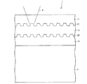
まず、光情報記録媒体1の構成について図1を参照して以下に説明する。図1は、光情報記録媒体1を部分的に示す断面図である。図1に示すように、光情報記録媒体1は、基板2と、基板2上に積層された3層の樹脂層11〜13とを備えている。樹脂層11は、例えば、厚さ75μmの透明紫外線硬化樹脂からなり、樹脂層12,13は、例えば、厚さ25μmの透明紫外線硬化樹脂からなる。
(Optical information recording medium 1)
First, the configuration of the optical information recording medium 1 will be described below with reference to FIG. FIG. 1 is a sectional view partially showing the optical information recording medium 1. As shown in FIG. 1, the optical information recording medium 1 includes a
基板2は、樹脂層11〜13を補強するために十分な強度を有するものであればよく、例えば、厚さ1.1mmの透明樹脂からなる。透明樹脂としては、例えば、ポリカーボネートやポリオレフィン樹脂などを用いることができる。また、再生光4は、樹脂層11側から入射するので、金属からなる基板2を用いてもよい。また多層構造であってもよい。
The board |
基板2上には、基板2側から順に、樹脂層13、樹脂層12、および樹脂層11が積層されている。樹脂層13において樹脂層12と接する面には、記録される情報に応じた凹凸形状のプリピット(情報ピット)が形成された後に樹脂層12が形成されている。同様に、樹脂層12において樹脂層11と接する面には、情報ピットが形成された後に樹脂層11が形成されている。その結果として、樹脂層13と樹脂層12との界面が情報記録面22を成しており、樹脂層12と樹脂層11との界面が情報記録面21を成している。各情報記録面21,22はROM面となっており、各情報記録面21,22に記録された情報は、樹脂層11側から入射する再生光4によって読み出すことができる。
On the board |
光情報記録媒体1では、樹脂層11〜13の各々は、2種類の異なる屈折率のいずれかを、隣接する樹脂層同士の屈折率が異なるようにして有していればよい。すなわち、樹脂層11,13が第1の屈折率を有し、樹脂層11と樹脂層13との間に配置される樹脂層12が第2の屈折率を有していればよい。具体的には、2種類の異なる屈折率を1.45と1.70とにする場合、樹脂層11の屈折率は1.45となり、樹脂層12の屈折率は1.70となり、樹脂層13の屈折率は1.45となる。このとき、隣接する樹脂層同士の屈折率の差はそれぞれ0.25となる。光情報記録媒体における透明な樹脂層の屈折率は、一般的に1.45〜1.70の範囲内で用いられることが多く、本構成は充分に実現可能な構成である。
In the optical information recording medium 1, each of the resin layers 11 to 13 only needs to have one of two different refractive indexes so that adjacent resin layers have different refractive indexes. That is, it is only necessary that the resin layers 11 and 13 have the first refractive index, and the
隣接する樹脂層11〜13間の界面は、反射界面(反射面)として機能する。図1に示すように、樹脂層11と樹脂層12との界面が情報記録面21であり、樹脂層12と樹脂層13との界面が情報記録面22である。再生光を各情報記録面21,22(すなわち各
反射界面)にフォーカスすることによって、各情報記録面21,22にて再生光の反射および回折が生じる。情報記録面21,22(の平坦部)における再生光の単独理論反射率は、理論上(計算上)0.6%となる。
The interface between the adjacent resin layers 11 to 13 functions as a reflection interface (reflection surface). As shown in FIG. 1, the interface between the
また、例えば2種類の屈折率を1.3と1.5とにする場合には、各情報記録面21,22おける単独理論反射率は0.5%となり、2種類の屈折率を1.5と1.7とにする場合には、情報記録面21,22における単独理論反射率は0.4%となる。 For example, when the two types of refractive indexes are set to 1.3 and 1.5, the single theoretical reflectance on each of the information recording surfaces 21 and 22 is 0.5%, and the two types of refractive indexes are set to 1. In the case of 5 and 1.7, the single theoretical reflectance at the information recording surfaces 21 and 22 is 0.4%.
なお、本発明における樹脂層11〜13の屈折率は、上記数値に限られず、反射界面を形成するために必要な差を有する2種類の屈折率から選ばれればよい。また、隣接する樹脂層同士の屈折率の差は、0.2以上であることが好ましい。一般的な透明樹脂の屈折率範囲内(例えば1.3〜1.7)であれば、屈折率の差を0.2以上とすることによって、情報記録面21,22における再生光の単独理論反射率を0.3%以上にすることができる。光情報記録媒体1においては、各反射面における透過率が充分に高く、吸収および散乱を事実上無視することができるので、各反射面における再生光の単独理論反射率と媒体反射率とは事実上ほぼ等しくなる。したがって、単独理論反射率を0.3%以上にすれば、媒体反射率は0.3%以上となる。媒体反射率が0.3%以上であれば、光情報記録媒体を再生する際に、フォーカスおよび再生に必要な信号強度を得ることができる。 In addition, the refractive index of the resin layers 11-13 in this invention is not restricted to the said numerical value, What is necessary is just to be selected from two types of refractive indexes which have a difference required in order to form a reflective interface. Further, the difference in refractive index between adjacent resin layers is preferably 0.2 or more. If it is within the range of the refractive index of a general transparent resin (for example, 1.3 to 1.7), by setting the difference in refractive index to 0.2 or more, the single theory of the reproduction light on the information recording surfaces 21 and 22 The reflectance can be 0.3% or more. In the optical information recording medium 1, the transmittance at each reflecting surface is sufficiently high, and absorption and scattering can be virtually ignored. Therefore, the single theoretical reflectance and medium reflectance of the reproduction light at each reflecting surface are the facts. Almost equal. Therefore, if the single theoretical reflectance is 0.3% or more, the medium reflectance is 0.3% or more. When the medium reflectance is 0.3% or more, it is possible to obtain signal intensity necessary for focusing and reproduction when reproducing an optical information recording medium.
また、樹脂層12の層厚については、情報記録面21における情報ピットと、情報記録面22における情報ピットとの間の距離を十分に有し、層間クロストークを防止できる程度の厚さがあればよい。層間クロストークとは、光情報記録媒体1の再生時に生じる、目的以外の情報記録面からの迷光による再生ノイズを意味する。
Further, the thickness of the
また、基板2から最も離れた側に配置される樹脂層11の層厚については、光情報記録媒体1に用いられる再生装置に応じて適宜変更可能である。さらに、樹脂層11には、基板2と反対側の表面に、表面保護のためのハードコートが設けられていてもよい。
Further, the thickness of the
(樹脂層11〜13の材料)
次に、樹脂層11〜13に用いられる材料について説明する。
(Material of resin layers 11-13)
Next, materials used for the resin layers 11 to 13 will be described.
樹脂層11〜13の材料には、透明な紫外線硬化樹脂を用いることが好ましい。紫外線硬化樹脂の屈折率は、一般に1.30〜1.70の範囲で調整される。樹脂層11〜13の材料について、本発明は紫外線硬化樹脂に限られず、再生光の波長に対して透過率が高く、かつ屈折率を調整できる樹脂であればよい。例えば、紫外線硬化樹脂以外の光硬化性樹脂であってもよいし、熱硬化性樹脂であってもよい。さらに、樹脂層11〜13の材料は、形成前に液状樹脂であるものに限られず、シート状のもの、固形状のもの、および基板状のものであってもよい。 As the material for the resin layers 11 to 13, it is preferable to use a transparent ultraviolet curable resin. The refractive index of the ultraviolet curable resin is generally adjusted in the range of 1.30 to 1.70. Regarding the material of the resin layers 11 to 13, the present invention is not limited to the ultraviolet curable resin, but may be any resin that has a high transmittance with respect to the wavelength of the reproduction light and can adjust the refractive index. For example, a photocurable resin other than an ultraviolet curable resin may be used, or a thermosetting resin may be used. Furthermore, the material of the resin layers 11 to 13 is not limited to a liquid resin before formation, and may be a sheet-like material, a solid material, or a substrate-like material.
なお、本明細書中において、「屈折率」とは、光情報記録媒体1に用いられる再生光の波長に対する屈折率のことを意味し、「透明」および「透過率が高い」とは、光情報記録媒体1に対する再生光の透過率が80%以上となることを意味する。 In the present specification, “refractive index” means a refractive index with respect to the wavelength of reproduction light used in the optical information recording medium 1, and “transparent” and “high transmittance” This means that the transmittance of the reproduction light to the information recording medium 1 is 80% or more.
また、基板2から最も離れて配置される樹脂層11は、紫外線硬化樹脂の他に、ポリカーボネートフィルムと透明粘着材とから形成されるものであってもよく、0.6mmのポリカーボネート基板であってもよい。
Further, the
紫外線硬化樹脂としては、エポキシ系、ビニル系、アクリル系、およびメタクリル系などがあり、それぞれ官能基として、エポキシ基、ビニル基、アクリル基、またはメタクリル基を有している。例えばアクリル系樹脂は、アクリレートモノマーやアクリレートオリ
ゴモノマーに光硬化開始剤などの配合物を加えた混合物から成る。
Examples of the ultraviolet curable resin include epoxy, vinyl, acrylic, and methacrylic resins, each having an epoxy group, a vinyl group, an acrylic group, or a methacryl group as a functional group. For example, the acrylic resin is composed of a mixture obtained by adding a compound such as a photocuring initiator to an acrylate monomer or an acrylate oligomonomer.
紫外線硬化樹脂の屈折率の調整は、一般的に、樹脂材料に対して屈折率の異なる他の材料を配合することによって行われる。配合される材料には、原子屈折の低いフッ素原子や、原子屈折の高い硫黄原子(他にも芳香族環、フッ素を除くハロゲンなど)を含む材料が用いられる。 Adjustment of the refractive index of the ultraviolet curable resin is generally performed by blending another material having a different refractive index with respect to the resin material. As a material to be blended, a material containing a fluorine atom having a low atomic refraction or a sulfur atom having a high atomic refraction (in addition, an aromatic ring, a halogen other than fluorine, etc.) is used.
通常、様々な紫外線硬化樹脂の中から使用する紫外線硬化樹脂を選定する際、光損失や硬化性のみを考慮して、種々の官能基を有する紫外線硬化樹脂を組み合わせて選定する場合がある。 Normally, when selecting an ultraviolet curable resin to be used from among various ultraviolet curable resins, there are cases where an ultraviolet curable resin having various functional groups is selected in combination in consideration of only light loss and curability.
これに対して、本発明では、樹脂層11〜13の材料に、それぞれ共通の官能基を有する紫外線硬化樹脂を用いることが好ましい。 On the other hand, in this invention, it is preferable to use the ultraviolet curable resin which has a respectively common functional group for the material of the resin layers 11-13.
上記構成によれば、樹脂層11〜13における線膨張係数、透湿度(湿度透過性)を近い値にすることができる。隣接する樹脂層同士の線膨張係数の差を小さくすれば、温度変化によって生じる樹脂層の応力や反りを防止することができる。また、隣接する樹脂層の透湿度を共通にすれば、樹脂において湿度分布が均一となり、湿度変化による応力や反りを防止することができる。さらに、特性の同様な樹脂層同士が接するため、樹脂同士の密着性が高まり、光情報記録媒体1の強度が向上する。 According to the said structure, the linear expansion coefficient in the resin layers 11-13 and a water vapor transmission rate (humidity permeability) can be made into a near value. If the difference in linear expansion coefficient between adjacent resin layers is reduced, stress and warpage of the resin layer caused by temperature change can be prevented. Further, if the moisture permeability of adjacent resin layers is made common, the humidity distribution in the resin becomes uniform, and stress and warpage due to humidity change can be prevented. Furthermore, since resin layers having similar characteristics are in contact with each other, the adhesion between the resins is increased, and the strength of the optical information recording medium 1 is improved.
また、樹脂層11〜13の材料には、透明紫外線硬化樹脂に対して透明微粒子を混合させた物を用いてもよい。透明微粒子には、金属酸化物または金属窒化物などを用いることができる。具体的には、酸化インジウム(In2O3)、酸化インジウム錫(ITO:In2SO3−Sn)、酸化錫(SnO2)、アンチモン含有酸化錫(ATO:SnO2−Sb)、酸化亜鉛(ZnO)、酸化チタン(TiO2)、石英(SiO2)、酸化アルミニウム(Al2O3)、チタン酸バリウム(BaTiO3)、および窒化シリコン(SiN)などが挙げられる。 Moreover, you may use the thing which mixed the transparent fine particle with the transparent ultraviolet curable resin as the material of the resin layers 11-13. A metal oxide or a metal nitride can be used for the transparent fine particles. Specifically, indium oxide (In 2 O 3 ), indium tin oxide (ITO: In 2 SO 3 —Sn), tin oxide (SnO 2 ), antimony-containing tin oxide (ATO: SnO 2 —Sb), zinc oxide (ZnO), titanium oxide (TiO 2 ), quartz (SiO 2 ), aluminum oxide (Al 2 O 3 ), barium titanate (BaTiO 3 ), and silicon nitride (SiN).
ここで、透明微粒子は、透明紫外線硬化樹脂の屈折率とは異なる屈折率を有すものであることが好ましい。例えば、屈折率が2.0の透明微粒子(酸化錫)を用いた場合、樹脂層11〜13の屈折率を、紫外線硬化樹脂の屈折率の範囲(1.30〜1.70)を超えた屈折率に調整することができる。また、透明紫外線硬化樹脂に混合する透明微粒子の量を調節することによって、樹脂層11〜13の屈折率を精度よく調整することができる。 Here, the transparent fine particles preferably have a refractive index different from that of the transparent ultraviolet curable resin. For example, when transparent fine particles (tin oxide) having a refractive index of 2.0 are used, the refractive index of the resin layers 11 to 13 exceeds the refractive index range (1.30 to 1.70) of the ultraviolet curable resin. The refractive index can be adjusted. Moreover, the refractive index of the resin layers 11-13 can be accurately adjusted by adjusting the quantity of the transparent fine particles mixed with transparent ultraviolet curable resin.
透明微粒子の粒径は、情報記録面21または22の凹凸形状に入り込むことができる程度に小さいことが好ましい。さらに、光情報記録媒体1を再生するとき、再生光の波長に対して再生ノイズを発生しない程度に小さいことが好ましい。
The particle diameter of the transparent fine particles is preferably small enough to enter the uneven shape of the
(光情報記録媒体1の製造方法)
光情報記録媒体1の製造方法について、図1を参照して以下に説明する。なお、以下の製造方法では、樹脂層11〜13の材料に紫外線硬化樹脂を用いているが、光情報記録媒体1の製造方法はこれに限られない。
(Method for manufacturing optical information recording medium 1)
A method for manufacturing the optical information recording medium 1 will be described below with reference to FIG. In the following manufacturing method, an ultraviolet curable resin is used as the material of the resin layers 11 to 13, but the manufacturing method of the optical information recording medium 1 is not limited to this.
光情報記録媒体1の製造方法は、以下の工程を含んでいる。 The manufacturing method of the optical information recording medium 1 includes the following steps.
(S1)基板2上に紫外線硬化樹脂(樹脂層13の材料)を塗布する。
(S1) An ultraviolet curable resin (material of the resin layer 13) is applied on the
(S2)情報ピットが形成されたスタンパを押圧することによって、工程S1において塗布した紫外線硬化樹脂にピット形状を転写する。 (S2) By pressing the stamper on which the information pits are formed, the pit shape is transferred to the ultraviolet curable resin applied in step S1.
(S3)ピット形状を転写しつつ、紫外線を照射して紫外線硬化樹脂を硬化させることによって、樹脂層13を形成する。
(S3) The
(S4)スタンパを除去した後、樹脂層13上に紫外線硬化樹脂(樹脂層12の材料)を塗布する。
(S4) After removing the stamper, an ultraviolet curable resin (material of the resin layer 12) is applied on the
(S5)情報ピットが形成されたスタンパを押圧することによって、工程S4において塗布した紫外線硬化樹脂にピット形状を転写する。 (S5) By pressing the stamper on which the information pits are formed, the pit shape is transferred to the ultraviolet curable resin applied in step S4.
(S6)ピット形状を転写しつつ、紫外線を照射して紫外線硬化樹脂を硬化させることによって、樹脂層12を形成する。
(S6) The
(S7)スタンパを除去した後、樹脂層12上に紫外線硬化樹脂(樹脂層11の材料)を塗布する。
(S7) After removing the stamper, an ultraviolet curable resin (material of the resin layer 11) is applied on the
(S8)紫外線を照射して紫外線硬化樹脂を硬化させることによって、樹脂層11を形成する。
(S8) The
以上の工程によって、光情報記録媒体1を製造することができる。 The optical information recording medium 1 can be manufactured through the above steps.
なお、本発明は、上記製造方法に限定されず、適宜変更可能である。例えば、上記製造方法における、液状の紫外線硬化樹脂を塗布する工程は、シート状の紫外線硬化樹脂を接着する工程に置換してもよく、最終的に形成された各樹脂層が所定の要件を満たしていればよい。
(光情報記録媒体1の多層化)
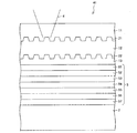
本発明によれば、さらに他の樹脂層を積層することによって、光情報記録媒体1をさらに多層化することが容易である。以下、多層化された光情報記録媒体40について図2を参照して説明する。図2は、光情報記録媒体40を部分的に示す断面図であり、光情報記録媒体1の構成要素と同様の構成要素には、同一符号を用いている。
In addition, this invention is not limited to the said manufacturing method, It can change suitably. For example, the step of applying a liquid UV curable resin in the above manufacturing method may be replaced with a step of bonding a sheet of UV curable resin, and each finally formed resin layer satisfies predetermined requirements. It only has to be.
(Multi-layered optical information recording medium 1)
According to the present invention, it is easy to further multilayer the optical information recording medium 1 by laminating other resin layers. Hereinafter, the multilayered optical
図2に示すように、光情報記録媒体40は、光情報記録媒体1の構成と比較して、さらに樹脂層14,15がさらに積層されている構成である。すなわち、光情報記録媒体40では、基板2上に5層の樹脂層11〜15が積層されている。樹脂層11は、例えば、厚さ70μmの透明紫外線硬化樹脂からなり、樹脂層12〜15は、例えば、厚さ10μmの透明紫外線硬化樹脂からなる。
As shown in FIG. 2, the optical
また、光情報記録媒体40においては、情報記録面21,22の他に、情報記録面23,24が形成されている。具体的には、樹脂層15と樹脂層14との界面が情報記録面24となり、樹脂層14と樹脂層13との界面が情報記録面23となる。
Further, in the optical
光情報記録媒体40においても、樹脂層11〜15の各々は、2種類の異なる屈折率のいずれかを、隣接する樹脂層同士の屈折率が異なるようにして有していればよい。樹脂層11〜15の各々が有する屈折率を、例えば1.45および1.70のいずれかとする場合、樹脂層11〜15の屈折率は、再生光4側から順に、1.45、1.70、1.45、1.70、1.45となる。このとき、隣接する樹脂層同士の屈折率の差は、全て0.25となる。
Also in the optical
上記構成によれば、光情報記録媒体40は、隣接する樹脂層の屈折率の差を十分に確保したまま、光情報記録媒体1を多層化した構成を実現している。
According to the above configuration, the optical
なお、光情報記録媒体1の多層化は、光情報記録媒体40に限られない。本発明によれば、積層される樹脂層の数は、樹脂層の材料の取り得る屈折率の数値範囲に制限されないため、さらに樹脂層の数を増加された光情報記録媒体を実現することができる。
Note that the multilayered optical information recording medium 1 is not limited to the optical
また、多層化された光情報記録媒体40においても、隣接する樹脂層の屈折率の差は常に一定である。このため、各情報記録面21〜24における再生光に対する単独理論反射率も全て均一な値であり、媒体反射率も全てほぼ均一な値となる。したがって、多層化された光情報記録媒体40を再生するとき、例えばフォーカスエラー信号などの、各情報記録面21〜24に対する再生条件を同様にして再生することができる。これによって、光情報記録媒体40を再生することが容易になる。
Also in the multilayered optical
(他の情報記録層との組み合わせ)
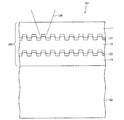
光情報記録媒体1は、樹脂層11〜13からなる樹脂層群と基板2との間に、他の情報記録層を設けてもよい。他の情報記録層として、RE(繰り返し書き込み可能)層を設けた光情報記録媒体41を図3に示す。図3は、光情報記録媒体41を部分的に示す断面図である。樹脂層11〜13は、図1に示した光情報記録媒体1と同様に構成されているので、ここではその説明を省略する。
(Combination with other information recording layers)
In the optical information recording medium 1, another information recording layer may be provided between the resin layer group including the resin layers 11 to 13 and the
図3に示すように、RE層5は7層の薄膜から構成されている。RE層5の各層については、第1保護膜51として厚さ35nmの硫化亜鉛−酸化シリコン(ZnS−SiO2)、第2保護膜52として厚さ5nmのZrO2、記録層53として厚さ10nmのGeTe−Sb2Te3、第3保護膜54として厚さ5nmのZrO2、第4保護膜55として厚さ35nmのZnS−SiO2、第5保護膜56として厚さ5nmのZrO2、及び反射膜57として厚さ20nmの銀パラジウム銅(APC:AgPdCu)を用いることができる。
As shown in FIG. 3, the
ただし、RE層5における各層の材料はこれらに限られるものではなく、RE層として機能するものであればよい。また、RE層5を形成する基板として、基板2の表面にはグルーブまたは凹凸が形成されていてもよい。
However, the material of each layer in the
光情報記録媒体41によれば、樹脂層11〜13までの透過率が高く、光利用効率が高いため、RE層5を記録再生する際に、従来よりも低い記録再生パワーによって、良好な記録再生ができる。
According to the optical
また、光情報記録媒体41の製造方法は、上述の光情報記録媒体1の製造方法において、工程S1の代わりに以下の工程を含む。
Moreover, the manufacturing method of the optical
(S1)RE層のグルーブなどの凹凸が形成された基板2に、反射膜57、第5保護膜56、第4保護膜55、第3保護膜54、記録層53、第2保護膜52、および第1保護膜51、を順次スパッタリングなどにより形成することによって、RE層5を形成する。
(S1) The
(S2)RE層5上に、紫外線硬化樹脂(樹脂層13の材料)を塗布する。
(S2) An ultraviolet curable resin (material of the resin layer 13) is applied on the
(S3)情報ピットが形成されたスタンパを押圧することによって、工程S2において塗布した紫外線硬化樹脂にピット形状を転写する。 (S3) By pressing the stamper on which the information pits are formed, the pit shape is transferred to the ultraviolet curable resin applied in step S2.
(S4)ピット形状を転写しつつ、紫外線を照射して紫外線硬化樹脂を硬化させることによって、樹脂層13を形成する。
(S4) The
(S5)スタンパを除去した後、樹脂層13上に紫外線硬化樹脂(樹脂層12の材料)を塗布する。
(S5) After removing the stamper, an ultraviolet curable resin (material of the resin layer 12) is applied on the
(S6)情報ピットが形成されたスタンパを押圧することによって、工程S4において塗布した紫外線硬化樹脂にピット形状を転写する。 (S6) By pressing the stamper on which the information pits are formed, the pit shape is transferred to the ultraviolet curable resin applied in step S4.
(S7)ピット形状を転写しつつ、紫外線を照射して紫外線硬化樹脂を硬化させることによって、樹脂層12を形成する。
(S7) The
(S8)スタンパを除去した後、樹脂層12上に紫外線硬化樹脂(樹脂層11の材料)を塗布する。
(S8) After removing the stamper, an ultraviolet curable resin (material of the resin layer 11) is applied on the
(S9)紫外線を照射して紫外線硬化樹脂を硬化させることによって、樹脂層11を形成する。
(S9) The
以上の工程によって、光情報記録媒体41を製造することができる。
The optical
(従来技術との比較)
本発明に係る光情報記録媒体1と、従来の光情報記録媒体との比較について以下に述べる。
(Comparison with conventional technology)
A comparison between the optical information recording medium 1 according to the present invention and a conventional optical information recording medium will be described below.
まず、本発明に係る光情報記録媒体1は、従来、各情報記録面に必ず設けられていた反射膜が不要となり、真空装置が必須の成膜工程が各情報記録面で不要になるので、製造が容易であり、かつ製造コストを低減することができる。 First, the optical information recording medium 1 according to the present invention eliminates the need for a reflective film that has always been provided on each information recording surface, and eliminates the need for a film forming process that requires a vacuum apparatus on each information recording surface. Manufacture is easy and manufacturing cost can be reduced.
次に、本発明に係る光情報記録媒体1では、樹脂層同士が接着しているいため、従来の光情報記録媒体における反射膜と樹脂層とのように異なる材料間が接着する場合よりも、密着性を確保することが容易となる。さらに、本発明に係る光情報記録媒体1では、樹脂層の母材を同じ官能基を有する材料とすることで、異なる官能基材料を主成分とする樹脂層間の密着性よりも、密着性が向上している。これらによって、光情報記録媒体1は、媒体の強度、耐久性、および信頼性を実現することができる。 Next, in the optical information recording medium 1 according to the present invention, since the resin layers are desired to be bonded to each other, compared to the case where different materials are bonded such as the reflective film and the resin layer in the conventional optical information recording medium, It becomes easy to ensure adhesion. Furthermore, in the optical information recording medium 1 according to the present invention, the base material of the resin layer is made of a material having the same functional group, so that the adhesiveness is higher than the adhesiveness between resin layers mainly composed of different functional group materials. It has improved. Thus, the optical information recording medium 1 can realize the strength, durability, and reliability of the medium.
次に、従来の光情報記録媒体では、反射膜の成膜によってステップカバレッジが悪くなるという問題がある。すなわち、反射膜の膜厚が増えるに従って、本来の凹凸形状がなまっていき、信号品質が低下してしまう。これに対して本発明に係る光情報記録媒体1では、各情報記録面21,22での情報再生を、反射界面による反射光にて行うため、本来形成された凹凸面にて情報再生が可能となり、従来よりも信号品質が向上する。 Next, the conventional optical information recording medium has a problem that the step coverage is deteriorated by the formation of the reflective film. That is, as the film thickness of the reflective film increases, the original uneven shape becomes distorted and the signal quality decreases. On the other hand, in the optical information recording medium 1 according to the present invention, information is reproduced on each of the information recording surfaces 21 and 22 by reflected light from the reflective interface, so that information can be reproduced on the originally formed uneven surface. Thus, the signal quality is improved as compared with the conventional case.
また、現在普及し始めている、より大容量に適した青色可視光領域を有する青色レーザ(波長略405nm)を再生光とした光情報記録媒体の場合、ROM面に薄く形成されるAg、Al、またはAu等の金属反射膜は、青色可視光領域において吸収係数を有するため、従来の赤色可視光領域である赤色レーザ(波長略660nm)と比較して、再生光照射による反射膜の劣化が激しく、十分な再生耐久性が得られない。これに対して、本発明に係る光情報記録媒体1によれば、反射膜が存在しないため、光吸収率が小さくなり、再生耐久性を向上させることができる。 In addition, in the case of an optical information recording medium using a blue laser (wavelength of about 405 nm) having a blue visible light region suitable for a larger capacity, which is becoming popular, as reproduction light, Ag, Al, Alternatively, a metal reflective film such as Au has an absorption coefficient in the blue visible light region, and therefore, the deterioration of the reflective film due to reproduction light irradiation is severe compared to a red laser (wavelength of about 660 nm) that is a conventional red visible light region. , Sufficient reproduction durability cannot be obtained. On the other hand, according to the optical information recording medium 1 according to the present invention, since there is no reflective film, the light absorptance is reduced and the reproduction durability can be improved.
さらに、3層構造以上の光情報記録媒体の場合、従来ROM層材料の中で最も透過率が得られるAgにおいて膜厚を均一に成膜できる限界程度まで薄く形成しても、青色レーザ波長における透過率は80%程度であり、その時の反射率は約10%となる。 Furthermore, in the case of an optical information recording medium having a three-layer structure or more, even if the film thickness is made thin enough to the extent that the film thickness can be uniformly formed in Ag that can obtain the most transmittance among conventional ROM layer materials, The transmittance is about 80%, and the reflectance at that time is about 10%.
これに対して本発明に係る光情報記録媒体1によれば、反射層が存在しないため、各情報記録面の透過率を高く保持し、単独理論反射率および媒体反射率を低く抑えることができる。したがって、本発明に係る光情報記録媒体1は、光利用効率が高く、多層光情報記録媒体として適している。さらに、光情報記録媒体1では、各樹脂層の屈折率を第1の屈折率と第2の屈折率に調整することによって、各情報記録面21,22の反射率制御が可能であり、反射層が存在しないことによって、従来では各情報記録面毎に必要とする反射層膜厚の調整および設計が不要となる。このため、光情報記録媒体1の製造が容易となる。
On the other hand, according to the optical information recording medium 1 of the present invention, since there is no reflective layer, the transmittance of each information recording surface can be kept high, and the single theoretical reflectance and the medium reflectance can be kept low. . Therefore, the optical information recording medium 1 according to the present invention has high light utilization efficiency and is suitable as a multilayer optical information recording medium. Furthermore, in the optical information recording medium 1, the reflectance of each
〔実施形態2〕
本発明の第2の実施形態について図4を参照して以下に説明する。図4は、本実施形態に係る光情報記録媒体42を部分的に示す断面図である。なお、実施形態1における要素と同様の要素には、同一符号を用いている。また、同様の要素についての説明は、実施形態1における説明を参照する。
[Embodiment 2]
A second embodiment of the present invention will be described below with reference to FIG. FIG. 4 is a sectional view partially showing the optical information recording medium 42 according to this embodiment. In addition, the same code | symbol is used for the element similar to the element in Embodiment 1. FIG. For the description of similar elements, refer to the description in the first embodiment.
樹脂層11は、例えば、厚さ75μmの透明紫外線硬化樹脂からなり、樹脂層12は、例えば、厚さ25μmの透明紫外線硬化樹脂からなる。基板2aは、例えば厚さ1.1mmの透明樹脂からなる。
The
図4に示すように、光情報記録媒体42では、基板2a上に、樹脂層11,12が積層されている。基板2aにおいて、樹脂層12と接する面には、情報ピットが形成されており、この面を情報記録面25とする。また、樹脂層12において、樹脂層11と接する面(情報記録面21)には、情報ピットが形成されている。各情報記録面21,25はROM面となっており、各情報記録面21,25に記録された情報は、樹脂層11側から入射する再生光4によって読み出すことができる。
As shown in FIG. 4, in the optical information recording medium 42, resin layers 11 and 12 are laminated on the
本実施形態においては、基板2aと樹脂層12との間の界面も、反射界面として機能する。このため、基板2aの屈折率も調整することが必要となる。すなわち、2種類の異なる屈折率のいずれかを、隣接する樹脂層同士の屈折率が異なるように有していればよい。基板2aと樹脂層11が第1の屈折率を有し、樹脂層12が第2の屈折率を有す。例えば、異なる2種の屈折率を1.45と1.70とにする場合、基板2aの屈折率は1.45であり、樹脂層11の屈折率は1.45であり、樹脂層12の屈折率は1.70である。
In the present embodiment, the interface between the
上記構成によれば、隣接する樹脂層11,12の屈折率の差と、基板2aと樹脂層12との屈折率の差とを、同様に0.25とする。これによって、光情報記録媒体42は、基板2aまで含めて、実施形態1における光情報記録媒体1と同様の効果を奏することができる。
According to the said structure, the difference of the refractive index of the adjacent resin layers 11 and 12 and the difference of the refractive index of the board |
なお、本実施形態における基板2aの材料には、樹脂層11,12と同様に、紫外線硬化樹脂などを用いてもよいし、屈折率条件を満たせば他の樹脂材料を用いてもよい。
As the material of the
(光情報記録媒体42の製造方法)
光情報記録媒体42の製造方法について、図4を参照して以下に説明する。なお、以下の製造方法では、基板2aおよび樹脂層11,12の材料に紫外線硬化樹脂を用いているが、光情報記録媒体1の製造方法はこれに限られない。
(Method for Manufacturing Optical Information Recording Medium 42)
A method for manufacturing the optical information recording medium 42 will be described below with reference to FIG. In the following manufacturing method, an ultraviolet curable resin is used as the material of the
光情報記録媒体42の製造方法は、以下の工程を含んでいる。 The manufacturing method of the optical information recording medium 42 includes the following steps.
(S1)情報ピットが形成された基板2a上に紫外線硬化樹脂(樹脂層12の材料)を塗布する。
(S1) An ultraviolet curable resin (material of the resin layer 12) is applied on the
(S2)情報ピットが形成されたスタンパを押圧することによって、工程S1において塗布した紫外線硬化樹脂にピット形状を転写する。 (S2) By pressing the stamper on which the information pits are formed, the pit shape is transferred to the ultraviolet curable resin applied in step S1.
(S3)ピット形状を転写しつつ、紫外線を照射して紫外線硬化樹脂を硬化させることによって、樹脂層12を形成する。
(S3) The
(S4)スタンパを除去した後、樹脂層12上に紫外線硬化樹脂(樹脂層11の材料)を塗布する。
(S4) After removing the stamper, an ultraviolet curable resin (material of the resin layer 11) is applied on the
(S5)紫外線を照射して紫外線硬化樹脂を硬化させることによって、樹脂層11を形成する。
(S5) The
以上の工程によって、光情報記録媒体42を製造することができる。 The optical information recording medium 42 can be manufactured through the above steps.
なお、本発明は、上記製造方法に限定されず、適宜変更可能である。例えば、上記製造方法における、液状の紫外線硬化樹脂を塗布する工程は、シート状の紫外線硬化樹脂を接着する工程に置換してもよく、最終的に形成された各樹脂層が所定の要件を満たしていればよい。 In addition, this invention is not limited to the said manufacturing method, It can change suitably. For example, the step of applying a liquid UV curable resin in the above manufacturing method may be replaced with a step of bonding a sheet of UV curable resin, and each finally formed resin layer satisfies predetermined requirements. It only has to be.
本発明について、実施例および比較例に基づいてより具体的に説明するが、本発明はこれに限定されるものではない。当業者は本発明の範囲を逸脱することなく、種々の変更、修正、および改変を行うことができる。 The present invention will be described more specifically based on examples and comparative examples, but the present invention is not limited to this. Those skilled in the art can make various changes, modifications, and alterations without departing from the scope of the present invention.
まず、実施例1および比較例2について説明する。 First, Example 1 and Comparative Example 2 will be described.
〔実施例1〕
実施例1には、上述の実施形態1における図1に示すような構成を有する光情報記録媒体を用いた。その具体的な構成については、以下に示す通りである。
[Example 1]
In Example 1, an optical information recording medium having the configuration shown in FIG. The specific configuration is as follows.
基板2には、直径120mm、および厚さ1.1mmの円盤状基板を用いた。なお、上記円盤状基板の材料には、屈折率1.58の透明なポリカーボネートを用いた。
As the
樹脂層11〜13の材料には透明紫外線効果樹脂を用い、樹脂層11の厚さは75μm、その他の樹脂層12,13の厚さは25μmとした。また、樹脂層11〜13の各屈折率は、再生光照射側から順に、1.45、1.70、1.45とした。なお、この屈折率および層厚は後述のBD規格の規定を満たす範囲内である。
Transparent ultraviolet effect resin was used for the material of the resin layers 11-13, the thickness of the
また、情報記録面21および22には、Blu−ray Disc(BD)規格の再生専用光情報記録媒体(BD−ROM)規格において、最短マーク長(0.149μm)のピットおよびスペースの繰り返しからなる連続パターンを、2P法(photo polymarization法)を用いて形成した。 In addition, the information recording surfaces 21 and 22 are composed of pits and spaces having the shortest mark length (0.149 μm) in the Blu-ray Disc (BD) standard for reproduction-only optical information recording media (BD-ROM). A continuous pattern was formed using a 2P method (photo polymerization method).
〔比較例1〕
比較例1には、従来の反射膜を有する光情報記録媒体101を用いた。
[Comparative Example 1]
In Comparative Example 1, an optical
光情報記録媒体101は、以下の方法によって製造した。この製造方法について、図5を参照して以下に説明する。図5は、光情報記録媒体101を部分的に示す断面図である。
The optical
まず、基板102上に形成した樹脂層113上に、情報記録面を形成した後、従来の金属半透明膜APCを用いて反射膜121を厚さ5nmで成膜した。その後、反射膜121上に樹脂層112を形成し、樹脂層112上に情報記録面を形成した後、金属半透明膜APCを用いて反射膜122を厚さ5nmで成膜した。その後、反射膜122上に樹脂層111を形成した。
First, an information recording surface was formed on the
なお、基板102、および樹脂層111〜113の層厚および材料は、実施例1と同様にした。また、樹脂層111〜113の屈折率は、3層とも1.6とし、従来どおり全て共通の屈折率とした。
The layer thickness and materials of the
次に、実施例1および比較例2に対して、信号強度、反射率、および光利用効率の評価を以下のようにして行った。 Next, with respect to Example 1 and Comparative Example 2, evaluation of signal intensity, reflectance, and light utilization efficiency was performed as follows.
〔信号強度および反射率の評価〕
信号強度については、実施例1の光情報記録媒体を、BD光学系(NA0.85、再生波長400nm〜410nm)で再生し、その信号強度(CNR:搬送波対雑音比、キャリア対ノイズ比)を測定した。なお、信号強度の測定は、BD光学系を媒体反射率に応じて調整した上で行った。
[Evaluation of signal strength and reflectance]
Regarding the signal intensity, the optical information recording medium of Example 1 was reproduced with a BD optical system (NA 0.85, reproduction wavelength 400 nm to 410 nm), and the signal intensity (CNR: carrier to noise ratio, carrier to noise ratio) was It was measured. The signal intensity was measured after adjusting the BD optical system according to the medium reflectance.
反射率については、実施例1の光情報記録媒体を、BD光学系(NA0.85、再生波長400nm〜410nm)で再生し、受光部で検出した反射光量に基づき、各情報記録面による反射率を計算した。なお、反射率の測定は、光情報記録媒体における凹凸の存在しない領域(平面部、ミラー部)を、フォーカスサーボ適用状態で測定した。 Regarding the reflectance, the optical information recording medium of Example 1 was reproduced by a BD optical system (NA 0.85, reproduction wavelength 400 nm to 410 nm), and the reflectance by each information recording surface based on the amount of reflected light detected by the light receiving unit. Was calculated. Note that the reflectance was measured in an area where no irregularities exist in the optical information recording medium (planar portion, mirror portion) in a state where the focus servo was applied.
ここで、本実施例における反射率(媒体反射率)は、次のように算出した。まず、ある情報記録面のミラー部(平面部)に焦点を当てて媒体へ照射した再生光の光量と、情報記録面で反射されて多層光情報記録媒体の外側で検出される反射光量との比率を算出した。それをさらに、絶対反射率が既知であるリファレンスディスクにて上記と同様の比率を算出した結果によって補正した。このため、本実施例における反射率(媒体反射率)は、絶対反射率となる。 Here, the reflectance (medium reflectance) in this example was calculated as follows. First, the amount of reproduction light irradiated onto the medium while focusing on a mirror portion (planar portion) of a certain information recording surface and the amount of reflected light reflected on the information recording surface and detected outside the multilayer optical information recording medium The ratio was calculated. It was further corrected by the result of calculating the same ratio as described above with a reference disk having a known absolute reflectance. For this reason, the reflectance (medium reflectance) in the present embodiment is an absolute reflectance.
また、比較例1については、実施例1と同様に評価を行った。 Further, Comparative Example 1 was evaluated in the same manner as Example 1.
その結果、信号強度の測定では、実施例1および比較例1のいずれにおいても、フォーカスおよびトラッキングを良好に行うことができ、各信号強度は、実用化が可能とされる信号強度である40dB以上をそれぞれ示した。 As a result, in the measurement of signal intensity, focusing and tracking can be performed satisfactorily in both Example 1 and Comparative Example 1, and each signal intensity is 40 dB or more, which is a signal intensity that can be put to practical use. Respectively.
しかしながら、実施例1では、2つの情報記録面おいて同程度の信号を得るために、再生パワーを同程度必要としたのに対し、比較例1では、反射膜121よりも反射膜122において、より高い再生パワーを必要とした。
However, in Example 1, in order to obtain the same level of signal on the two information recording surfaces, the same level of reproduction power was required, whereas in Comparative Example 1, the
反射率の測定では、実施例1の反射率は、情報記録面21および22において、ともに約0.6%であった。一方、比較例1の反射率は、反射膜121において約10%であり、反射膜122において約6%であった。
In the measurement of reflectance, the reflectance of Example 1 was about 0.6% on the information recording surfaces 21 and 22. On the other hand, the reflectance of Comparative Example 1 was about 10% in the
比較例1では、反射膜121の金属半透明膜APCによって透過光量が減少し、反射膜122を再生する際により高い再生パワーが必要となったと考えられる。さらに、反射膜122において再生光が反射した後も、再度、反射膜121を透過する必要があるため、各反射膜121,122における反射率が異なったと考えられる。
In Comparative Example 1, it is considered that the amount of transmitted light is reduced by the metal translucent film APC of the
〔光利用効率の評価〕
光利用効率の評価を以下の方法で行った。
[Evaluation of light utilization efficiency]
The light utilization efficiency was evaluated by the following method.
実施例1および比較例1において、再生光入射側から見てさらに奥側に仮想層X(記録層もしくは再生層)が存在すると仮定する。仮想層Xに到達する光量が大きければ大きいほど光利用効率が大きく、仮想層Xにおける信号品質の劣化が少なく、仮想層Xを始めとしたさらなる多層化に有利であるということになる。 In Example 1 and Comparative Example 1, it is assumed that a virtual layer X (recording layer or reproducing layer) exists further on the back side when viewed from the reproducing light incident side. The larger the amount of light reaching the virtual layer X, the higher the light utilization efficiency, the less the signal quality degradation in the virtual layer X, and the more advantageous the multilayering including the virtual layer X.
実施例1の場合は、樹脂層11、情報記録面21、樹脂層12、情報記録面22、および樹脂層13を透過した再生光の光量が仮想層Xへの到達光量に相当する。比較例1の場合は、樹脂層111、反射膜121、樹脂層112、反射膜122、および樹脂層113を透過した再生光が同様に仮想層Xへの到達光量に相当する。実際に多層化した場合、仮想層Xへの到達光量を評価する際は、仮想層Xでのみ再生光がフォーカスするため、それまでの層においては集光途中の傾斜光が透過するのであるが、相対比較には平行光による評価で十分である。従って、上記光情報記録媒体の凹凸(情報ピット)の存在しないミラー部を透過した平行光の透過光量を比較すれば仮想層Xへの到達光量を評価することができる。
In the case of Example 1, the amount of reproduction light transmitted through the
そこで、実施例1および比較例1の光情報記録媒体のミラー部に、実施例1では樹脂層11から基板2へ、また比較例1では樹脂層111から基板102へ光を透過させ、分光光度計にて透過率を測定して比較を行った。この測定では、実際には、基板2または基板102をも透過した光を測定しているが、実施例1の基板2、および比較例1の基板102には、共に屈折率1.58の透明なポリカーボネートを用いたため、相対的な透過光量比較を行うことは可能である。
Therefore, light is transmitted from the
その結果、実施例1の透過率は、約85%であり、比較例1の透過率は約55%であった。したがって、実施例1は仮想層Xへの到達光量、すなわち光利用効率において比較例1を大きく上回ることが分かった。すなわち、実施例1の方がさらなる多層化に有利であると言える。 As a result, the transmittance of Example 1 was about 85%, and the transmittance of Comparative Example 1 was about 55%. Therefore, it was found that Example 1 far exceeded Comparative Example 1 in the amount of light reaching the virtual layer X, that is, the light utilization efficiency. That is, it can be said that Example 1 is more advantageous for further multilayering.
多層化された光情報記録媒体では、再生光入射側から見て最も奥に配置された情報記録面(この評価の場合仮想層X)に到達する再生光の光量が大きいほど、光利用効率が大きいと言える。光利用効率が大きければ、奥に配置された情報記録面における信号品質の劣化が少ないため、実施例1は、光情報記録媒体の多層化に有利な構成となる。 In a multilayered optical information recording medium, the greater the amount of reproduction light that reaches the information recording surface (the virtual layer X in this evaluation) arranged at the farthest when viewed from the reproduction light incident side, the more efficient the light utilization. It can be said that it is big. If the light use efficiency is high, the signal quality is less deteriorated on the information recording surface arranged at the back, so the first embodiment is advantageous for multilayering optical information recording media.
本発明は、例えばCD−ROM、CD−R、CD−RW、DVD−ROM、DVD−RW、BD、およびBD−ROMなどの光学読取式のディスク、光磁気ディスク、ならびに相変化型ディスクなどの種々の光情報記録媒体に適用することができる。 The present invention relates to optically readable discs such as CD-ROM, CD-R, CD-RW, DVD-ROM, DVD-RW, BD, and BD-ROM, magneto-optical disc, and phase change disc. The present invention can be applied to various optical information recording media.
1,40〜42、101 光情報記録媒体
2、2a、102 基板
4 再生光
11〜15、111〜113 樹脂層
21〜25 情報記録面
1, 40-42, 101 Optical
Claims (5)
第1の屈折率を有する樹脂層と第2の屈折率を有する樹脂層とを交互に積層することによって形成された3層以上の樹脂層を備えている、ことを特徴とする光情報記録媒体。 An optical information recording medium having a reflection surface at an interface between resin layers,
An optical information recording medium comprising three or more resin layers formed by alternately laminating a resin layer having a first refractive index and a resin layer having a second refractive index .
第1の屈折率を有する樹脂層と第2の屈折率を有する樹脂層とを交互に積層することによって、3層以上の樹脂層を形成する工程を含んでいる、ことを特徴とする光情報記録媒体の製造方法。 A method for producing an optical information recording medium having a reflection surface at an interface between resin layers,
An optical information comprising a step of forming three or more resin layers by alternately laminating a resin layer having a first refractive index and a resin layer having a second refractive index. A method for manufacturing a recording medium.
Priority Applications (1)
| Application Number | Priority Date | Filing Date | Title |
|---|---|---|---|
| JP2008169420A JP4890507B2 (en) | 2008-06-27 | 2008-06-27 | Optical information recording medium and manufacturing method thereof |
Applications Claiming Priority (1)
| Application Number | Priority Date | Filing Date | Title |
|---|---|---|---|
| JP2008169420A JP4890507B2 (en) | 2008-06-27 | 2008-06-27 | Optical information recording medium and manufacturing method thereof |
Publications (2)
| Publication Number | Publication Date |
|---|---|
| JP2010009702A true JP2010009702A (en) | 2010-01-14 |
| JP4890507B2 JP4890507B2 (en) | 2012-03-07 |
Family
ID=41589991
Family Applications (1)
| Application Number | Title | Priority Date | Filing Date |
|---|---|---|---|
| JP2008169420A Expired - Fee Related JP4890507B2 (en) | 2008-06-27 | 2008-06-27 | Optical information recording medium and manufacturing method thereof |
Country Status (1)
| Country | Link |
|---|---|
| JP (1) | JP4890507B2 (en) |
Cited By (4)
| Publication number | Priority date | Publication date | Assignee | Title |
|---|---|---|---|---|
| WO2010061557A1 (en) * | 2008-11-26 | 2010-06-03 | パナソニック株式会社 | Information recording medium, recording device, reproduction device, and reproduction method |
| WO2010064372A1 (en) * | 2008-12-01 | 2010-06-10 | パナソニック株式会社 | Information recording medium, recording device, reproduction device, and reproduction method |
| JP2012089211A (en) * | 2010-10-21 | 2012-05-10 | Tdk Corp | Multilayer optical recording medium |
| JP2012164405A (en) * | 2011-02-09 | 2012-08-30 | Tdk Corp | Multilayer optical recording medium |
Citations (5)
| Publication number | Priority date | Publication date | Assignee | Title |
|---|---|---|---|---|
| JP2003242677A (en) * | 2002-02-13 | 2003-08-29 | Ricoh Co Ltd | Multilayer recording medium and system using the same |
| JP2005071601A (en) * | 2004-11-01 | 2005-03-17 | Sony Corp | Method of manufacturing multilayered optical disk |
| JP2005346791A (en) * | 2004-06-01 | 2005-12-15 | Tdk Corp | Optical recording medium and its manufacturing method |
| JP2006052260A (en) * | 2004-08-10 | 2006-02-23 | Lintec Corp | Coating composition, coated film, method for producing the coated film, and optical recording medium |
| JP2006227419A (en) * | 2005-02-18 | 2006-08-31 | Fuji Photo Film Co Ltd | Optical film, antireflection film, polarizer, display apparatus, hard coat film, and optical information recording medium |
-
2008
- 2008-06-27 JP JP2008169420A patent/JP4890507B2/en not_active Expired - Fee Related
Patent Citations (5)
| Publication number | Priority date | Publication date | Assignee | Title |
|---|---|---|---|---|
| JP2003242677A (en) * | 2002-02-13 | 2003-08-29 | Ricoh Co Ltd | Multilayer recording medium and system using the same |
| JP2005346791A (en) * | 2004-06-01 | 2005-12-15 | Tdk Corp | Optical recording medium and its manufacturing method |
| JP2006052260A (en) * | 2004-08-10 | 2006-02-23 | Lintec Corp | Coating composition, coated film, method for producing the coated film, and optical recording medium |
| JP2005071601A (en) * | 2004-11-01 | 2005-03-17 | Sony Corp | Method of manufacturing multilayered optical disk |
| JP2006227419A (en) * | 2005-02-18 | 2006-08-31 | Fuji Photo Film Co Ltd | Optical film, antireflection film, polarizer, display apparatus, hard coat film, and optical information recording medium |
Cited By (5)
| Publication number | Priority date | Publication date | Assignee | Title |
|---|---|---|---|---|
| WO2010061557A1 (en) * | 2008-11-26 | 2010-06-03 | パナソニック株式会社 | Information recording medium, recording device, reproduction device, and reproduction method |
| US8259556B2 (en) | 2008-11-26 | 2012-09-04 | Panasonic Corporation | Information recording medium, recording apparatus, reproducing apparatus and reproducing method |
| WO2010064372A1 (en) * | 2008-12-01 | 2010-06-10 | パナソニック株式会社 | Information recording medium, recording device, reproduction device, and reproduction method |
| JP2012089211A (en) * | 2010-10-21 | 2012-05-10 | Tdk Corp | Multilayer optical recording medium |
| JP2012164405A (en) * | 2011-02-09 | 2012-08-30 | Tdk Corp | Multilayer optical recording medium |
Also Published As
| Publication number | Publication date |
|---|---|
| JP4890507B2 (en) | 2012-03-07 |
Similar Documents
| Publication | Publication Date | Title |
|---|---|---|
| TWI260622B (en) | Optical recording medium and method for recording and reproducing data | |
| JPS6127815B2 (en) | ||
| WO1999000794A1 (en) | Optical recording medium and optical disk device | |
| JP4136980B2 (en) | Multi-layer phase change information recording medium and recording / reproducing method thereof | |
| JP2003051140A (en) | Optical disk and method of manufacturing the same | |
| JP2010218636A (en) | Method of manufacturing optical recording medium, and optical recording medium | |
| KR100994944B1 (en) | System comprising an optical information medium and an apparatus for reading/recording | |
| JPS5990248A (en) | Information recording medium | |
| JP2000011454A (en) | Optical recording medium, optical recording and reproducing device using in, and manufacture thereof | |
| JP4890507B2 (en) | Optical information recording medium and manufacturing method thereof | |
| WO2011132371A1 (en) | Optical recording medium | |
| JP2011042070A5 (en) | ||
| US6747944B2 (en) | Optical recording medium | |
| JP4342439B2 (en) | Double stacked optical data storage media and use of such media | |
| JPH09320117A (en) | Optical disk | |
| JP2001101709A (en) | Optical recording medium, optical recording medium producing method and optical recording method | |
| US8144561B2 (en) | Multilayer optical recording medium | |
| JP2003242677A (en) | Multilayer recording medium and system using the same | |
| JPH11283278A (en) | Optical recording medium | |
| JP2004327007A (en) | Optical information recording medium and reproducing device | |
| JP4071060B2 (en) | Multi-layer phase change information recording medium and information recording / reproducing method using the same | |
| JP2009093750A (en) | Optical information recording medium | |
| WO2012035740A1 (en) | Optical recording medium | |
| JP2005092927A (en) | Multilayer optical disk | |
| JP2006252706A (en) | Optical recording medium and manufacturing method of optical recording medium |
Legal Events
| Date | Code | Title | Description |
|---|---|---|---|
| A621 | Written request for application examination |
Free format text: JAPANESE INTERMEDIATE CODE: A621 Effective date: 20100826 |
|
| A977 | Report on retrieval |
Free format text: JAPANESE INTERMEDIATE CODE: A971007 Effective date: 20110826 |
|
| A131 | Notification of reasons for refusal |
Free format text: JAPANESE INTERMEDIATE CODE: A131 Effective date: 20110830 |
|
| A521 | Request for written amendment filed |
Free format text: JAPANESE INTERMEDIATE CODE: A523 Effective date: 20111018 |
|
| TRDD | Decision of grant or rejection written | ||
| A01 | Written decision to grant a patent or to grant a registration (utility model) |
Free format text: JAPANESE INTERMEDIATE CODE: A01 Effective date: 20111122 |
|
| A01 | Written decision to grant a patent or to grant a registration (utility model) |
Free format text: JAPANESE INTERMEDIATE CODE: A01 |
|
| A61 | First payment of annual fees (during grant procedure) |
Free format text: JAPANESE INTERMEDIATE CODE: A61 Effective date: 20111214 |
|
| R150 | Certificate of patent or registration of utility model |
Free format text: JAPANESE INTERMEDIATE CODE: R150 |
|
| FPAY | Renewal fee payment (event date is renewal date of database) |
Free format text: PAYMENT UNTIL: 20141222 Year of fee payment: 3 |
|
| LAPS | Cancellation because of no payment of annual fees |