JP2010009570A - Computer implemented method for energy conservation in multipath data communication, computer usable program product, and data processing system - Google Patents
Computer implemented method for energy conservation in multipath data communication, computer usable program product, and data processing system Download PDFInfo
- Publication number
- JP2010009570A JP2010009570A JP2008273948A JP2008273948A JP2010009570A JP 2010009570 A JP2010009570 A JP 2010009570A JP 2008273948 A JP2008273948 A JP 2008273948A JP 2008273948 A JP2008273948 A JP 2008273948A JP 2010009570 A JP2010009570 A JP 2010009570A
- Authority
- JP
- Japan
- Prior art keywords
- computer
- computer usable
- usable code
- additional
- indication
- Prior art date
- Legal status (The legal status is an assumption and is not a legal conclusion. Google has not performed a legal analysis and makes no representation as to the accuracy of the status listed.)
- Granted
Links
Images


Classifications
-
- G—PHYSICS
- G06—COMPUTING; CALCULATING OR COUNTING
- G06F—ELECTRIC DIGITAL DATA PROCESSING
- G06F3/00—Input arrangements for transferring data to be processed into a form capable of being handled by the computer; Output arrangements for transferring data from processing unit to output unit, e.g. interface arrangements
- G06F3/06—Digital input from, or digital output to, record carriers, e.g. RAID, emulated record carriers or networked record carriers
- G06F3/0601—Interfaces specially adapted for storage systems
- G06F3/0602—Interfaces specially adapted for storage systems specifically adapted to achieve a particular effect
- G06F3/0625—Power saving in storage systems
-
- G—PHYSICS
- G06—COMPUTING; CALCULATING OR COUNTING
- G06F—ELECTRIC DIGITAL DATA PROCESSING
- G06F1/00—Details not covered by groups G06F3/00 - G06F13/00 and G06F21/00
- G06F1/26—Power supply means, e.g. regulation thereof
- G06F1/32—Means for saving power
- G06F1/3203—Power management, i.e. event-based initiation of a power-saving mode
- G06F1/3206—Monitoring of events, devices or parameters that trigger a change in power modality
- G06F1/3215—Monitoring of peripheral devices
- G06F1/3221—Monitoring of peripheral devices of disk drive devices
-
- G—PHYSICS
- G06—COMPUTING; CALCULATING OR COUNTING
- G06F—ELECTRIC DIGITAL DATA PROCESSING
- G06F3/00—Input arrangements for transferring data to be processed into a form capable of being handled by the computer; Output arrangements for transferring data from processing unit to output unit, e.g. interface arrangements
- G06F3/06—Digital input from, or digital output to, record carriers, e.g. RAID, emulated record carriers or networked record carriers
- G06F3/0601—Interfaces specially adapted for storage systems
- G06F3/0628—Interfaces specially adapted for storage systems making use of a particular technique
- G06F3/0629—Configuration or reconfiguration of storage systems
- G06F3/0634—Configuration or reconfiguration of storage systems by changing the state or mode of one or more devices
-
- G—PHYSICS
- G06—COMPUTING; CALCULATING OR COUNTING
- G06F—ELECTRIC DIGITAL DATA PROCESSING
- G06F3/00—Input arrangements for transferring data to be processed into a form capable of being handled by the computer; Output arrangements for transferring data from processing unit to output unit, e.g. interface arrangements
- G06F3/06—Digital input from, or digital output to, record carriers, e.g. RAID, emulated record carriers or networked record carriers
- G06F3/0601—Interfaces specially adapted for storage systems
- G06F3/0668—Interfaces specially adapted for storage systems adopting a particular infrastructure
- G06F3/0671—In-line storage system
- G06F3/0683—Plurality of storage devices
-
- Y—GENERAL TAGGING OF NEW TECHNOLOGICAL DEVELOPMENTS; GENERAL TAGGING OF CROSS-SECTIONAL TECHNOLOGIES SPANNING OVER SEVERAL SECTIONS OF THE IPC; TECHNICAL SUBJECTS COVERED BY FORMER USPC CROSS-REFERENCE ART COLLECTIONS [XRACs] AND DIGESTS
- Y02—TECHNOLOGIES OR APPLICATIONS FOR MITIGATION OR ADAPTATION AGAINST CLIMATE CHANGE
- Y02D—CLIMATE CHANGE MITIGATION TECHNOLOGIES IN INFORMATION AND COMMUNICATION TECHNOLOGIES [ICT], I.E. INFORMATION AND COMMUNICATION TECHNOLOGIES AIMING AT THE REDUCTION OF THEIR OWN ENERGY USE
- Y02D10/00—Energy efficient computing, e.g. low power processors, power management or thermal management
Landscapes
- Engineering & Computer Science (AREA)
- Theoretical Computer Science (AREA)
- Physics & Mathematics (AREA)
- General Engineering & Computer Science (AREA)
- General Physics & Mathematics (AREA)
- Human Computer Interaction (AREA)
- Power Sources (AREA)
Abstract
Description
本発明は、改良されたデータ処理システムに関し、特にマルチパス・データ通信のためのコンピュータ実行される方法に関する。さらに特に、本発明は、マルチパス・データ通信におけるエネルギー節約のためのコンピュータ実行される方法、システム、およびコンピュータ使用可能なプログラム・コードに関する。 The present invention relates to an improved data processing system, and more particularly to a computer-implemented method for multipath data communication. More particularly, the present invention relates to computer-implemented methods, systems, and computer usable program code for energy saving in multipath data communications.
データ処理システムは、論理的パーティション(LPAR)に分割され得る。論理的パーティションは単に“パーティション”としても知られている。各パーティションは、他のパーティションとは無関係に別個のデータ処理システムとして動作する。一般に、パーティション管理ファームウェアが種々のパーティションを接続して、それらの間にネットワーク接続性を提供する。ハイパーバイザ(Hypervisor)は、そのようなパーティション管理ファームウェアの一例である。 A data processing system may be divided into logical partitions (LPARs). Logical partitions are also known simply as “partitions”. Each partition operates as a separate data processing system independent of other partitions. In general, partition management firmware connects the various partitions and provides network connectivity between them. A hypervisor is an example of such partition management firmware.
パーティションは、データを読み出し、書き込み、格納し、管理するために1つ以上のデータ記憶装置にアクセスすることができる。或る分割型データ処理システムでは、仮想入出力(I/O)サーバがパーティションに1つ以上のデータ記憶装置へのアクセスを提供する。データ記憶装置は、ストレージ・アレイあるいはストレージ・エリア・ネットワーク(SAN)の場合のように、ハードディスクのような1つ以上の物理的データ記憶ユニットを含むことができる。 A partition can access one or more data storage devices to read, write, store, and manage data. In some partitioned data processing systems, virtual input / output (I / O) servers provide a partition with access to one or more data storage devices. A data storage device may include one or more physical data storage units, such as a hard disk, as in a storage array or storage area network (SAN).
仮想I/Oサーバを使用しあるいは使用しないパーティションは、2つ以上のデータ通信経路を介して特定のデータ記憶装置にアクセスすることができる。パーティションとデータ記憶装置との間で2つ以上のデータ通信経路を介して行われるデータ通信はマルチパス入出力(マルチパスI/O)と呼ばれる。 A partition with or without a virtual I / O server can access a particular data storage device via two or more data communication paths. Data communication performed between a partition and a data storage device via two or more data communication paths is called multipath input / output (multipath I / O).
マルチパスI/Oを利用するパーティションは、データ記憶装置と通信するために複数のI/Oアダプタを使用することができる。各I/Oアダプタは別個のデータ・ネットワークを介してデータ記憶装置と通信する。マルチパスI/Oコンフィギュレーションは、パーティションとデータ記憶装置との間のデータ・スループット・レートを増大させるために分割型データ処理システムでよく使われる。マルチパスI/Oコンフィギュレーションは、また、パーティションとデータ記憶装置との間のデータ通信の信頼性を、それらの間に冗長データ通信経路を提供することによって、改善する。 A partition that utilizes multipath I / O can use multiple I / O adapters to communicate with a data storage device. Each I / O adapter communicates with the data storage device via a separate data network. Multipath I / O configurations are often used in partitioned data processing systems to increase the data throughput rate between partitions and data storage devices. Multipath I / O configuration also improves the reliability of data communication between the partition and the data storage device by providing a redundant data communication path between them.
本発明は、マルチパス・データ通信におけるエネルギー節約を目的とする。 The present invention aims to save energy in multipath data communications.
実施例は、マルチパス・データ通信におけるエネルギー節約のための方法、システム、およびコンピュータ使用可能なプログラム製品を提供する。数個のI/O装置の各々の現在の使用率が判定される。数個のI/O装置のうちのI/O装置がルールに違反せずにパワー・ダウンされ得るか否かを判定する、違反判定を形成する判定が行われる。そのI/O装置は、違反判定が偽であることに応答してパワー・ダウンされる。 The embodiments provide a method, system, and computer usable program product for energy saving in multipath data communications. The current usage rate of each of several I / O devices is determined. A determination is made to form a violation determination that determines whether an I / O device of several I / O devices can be powered down without violating a rule. The I / O device is powered down in response to the violation determination being false.
マルチパスI/Oコンフィギュレーションにおいて追加のI/O装置が必要か否かを判定する、パワー・アップ判定を形成する判定が行われ得る。そのI/O装置が特定され得る。そのI/O装置はパワー・アップされ得る。そのI/O装置はマルチパスI/Oコンフィギュレーションのために利用可能にされ得る。そのI/O装置の特定が履行されないことに応答してユーザに対して通知が行われ得る。 A determination may be made that forms a power-up determination that determines whether additional I / O devices are required in a multipath I / O configuration. The I / O device can be identified. The I / O device can be powered up. The I / O device may be made available for multipath I / O configuration. A notification may be made to the user in response to the identification of the I / O device not being implemented.
追加のI/O装置が必要とされる時間が判定され得る。追加のI/O装置が必要とされる時間より前に該I/O装置の待ち時間が経過し得るか否かを判定する、待ち時間判定を形成する判定が行われ得る。そのI/O装置は、待ち時間判定が真であることに応答してパワー・オンされ得る。一実施態様では、そのパワー・オンは、追加のI/O装置が必要とされる時間より前に遅くとも待ち時間までに行われ得る。 The time required for additional I / O devices can be determined. A determination may be made that forms a latency determination that determines whether the latency of the I / O device may elapse before the time that the additional I / O device is required. The I / O device may be powered on in response to the latency determination being true. In one embodiment, the power on may occur at the latest, but not later than the time that additional I / O devices are needed.
パワー・アップ判定は、追加のI/O装置を求めるリクエストを受け取ること、あるいは追加のI/O装置に対するニーズを予測することをさらに含み得る。違反判定は、ルールを実行すること、システム・ポリシーを実行すること、あるいはコンフィギュレーションを実行することをさらに含むことができる。パワー・ダウンは、I/O装置をパワー・ダウンするロジックをルールに基いて作動させることをさらに含み得る。 The power up determination may further include receiving a request for additional I / O devices or predicting a need for additional I / O devices. Violation determination can further include executing rules, executing system policies, or performing configuration. Powering down may further include operating logic to power down the I / O device based on rules.
本発明を特徴付けると考えられる新規な特徴が、添付されている請求項に記載されている。しかし、本発明自体は、好ましい使用方法、その更なる目的および利点と共に、実施例についての以下の詳細な説明を添付図面と関連させて読んだときに最善に理解されるであろう。 The novel features believed characteristic of the invention are set forth in the appended claims. However, the present invention itself, together with preferred methods of use, its further objects and advantages, will be best understood when the following detailed description of the embodiments is read in conjunction with the accompanying drawings.
本書において記載される実施例は、マルチパス・データ通信におけるエネルギー節約のための方法、システム、およびコンピュータ使用可能なプログラム製品を提供する。実施例は、本書において時には記述を明瞭にするためにパーティションと特定のパーティション技術とを単なる一例として用いて記載される。実施例は、いろいろなデータ処理システムにおいてマルチパスI/Oを記述された仕方で管理するために使用され得る。例えば、マルチパスI/Oコンフィギュレーションを採用する非分割型システムは、実施例の範囲内でここに記載された仕方で該実施例を用いることができる。 The embodiments described herein provide methods, systems, and computer usable program products for energy saving in multipath data communications. Embodiments are described herein using partitions and specific partition techniques as examples only, sometimes for clarity of description. Embodiments may be used to manage multipath I / O in a manner described in various data processing systems. For example, a non-partitioned system that employs a multipath I / O configuration can use the embodiments in the manner described herein within the scope of the embodiments.
現在利用可能なマルチパスI/Oソリューションがデータ処理システムとデータ記憶装置との間のI/Oのために、ネットワーク・アダプタなどの、設定されているI/O装置の全部または大部分を使用するということを実施例は認識している。さらに、現在利用可能なマルチパスI/Oソリューションは、しばしば、それらのI/O装置を充分に活用しない。活用が不十分であることは、一般に、I/O装置と、関連するデータ・ネットワークとが全体としてパーティションまたはデータ処理システムが必要とするより大きなデータ収容能力を持っていることに起因する。 Currently available multipath I / O solutions use all or most of the configured I / O devices, such as network adapters, for I / O between data processing systems and data storage devices The embodiment recognizes that it does. Furthermore, currently available multipath I / O solutions often do not fully utilize their I / O devices. Insufficient utilization generally results from the I / O devices and associated data networks generally having more data capacity than the partition or data processing system requires.
実施例は、マルチパスI/Oを使用する現在の方法が計算リソースに関して不経済であり、またエネルギーに関して不経済であることを認識している。一例として、一つの代表的なマルチパス・データ通信コンフィギュレーションでは、I/O装置のうちの幾つかは動作可能な状態に留まっているが、どんなデータも全く伝達できないということがあり得る。動作可能であるということは、パワー・オンされた状態にあり、指示された機能を何時でも実行できるということである。動作可能であることにより、I/O装置は電力を消費する。しかし、実施例が認識しているように、データ通信に携わっていないかもしれないネットワーク・アダプタでは、その電力は浪費されている。 The example recognizes that current methods using multipath I / O are uneconomical with respect to computational resources and uneconomical with respect to energy. As an example, in one typical multipath data communication configuration, some of the I / O devices remain operational, but no data can be transmitted at all. Being operational means that it is powered on and can perform the indicated function at any time. Being operational allows the I / O device to consume power. However, as the embodiments recognize, power is wasted on network adapters that may not be engaged in data communications.
さらに、マルチパスI/Oコンフィギュレーションにおいてたとえ幾つかのI/O装置がデータ通信に携わっているかもしれなくても、それらのI/O装置を解放するようにデータ通信を調整できることを実施例は認識している。例えば、1つのI/O装置は、自分のデータ通信能力の僅か20パーセントを利用しているに過ぎないかもしれない。第2のI/O装置は、自分のデータ通信能力の40パーセントを利用しているかもしれない。従って、これらのI/O装置は、パワー・アップされて自分たちが動作可能であるために必要とする電力の全部を消費しているけれども、不十分に利用されているに過ぎない。実施例は、このようなI/O装置で電力がまた無駄に消費されていることを認識する。 Further, in the multipath I / O configuration, even if some I / O devices may be engaged in data communication, the data communication can be adjusted so as to release those I / O devices. Is aware. For example, an I / O device may only use 20 percent of its data communication capability. The second I / O device may be using 40 percent of its data communication capability. Thus, these I / O devices are powered up and consume all of the power they need to be able to operate, but are underutilized. The embodiment recognizes that power is also wasted in such an I / O device.
受信者のグループに電子メールを送ることに関連するこれらの及び他の問題に対処するために、実施例は、マルチパス・データ通信におけるエネルギー節約のための方法、システムおよびコンピュータ使用可能なプログラム製品を提供する。実施例によれば、第1I/O装置のデータ通信は第2I/O装置に移され得る。移されたデータ通信は、第2I/O装置の使用率を増大させ、第1I/O装置の使用率をゼロに減少させることができ、第1I/O装置は最早データ通信に携わらないかもしれない。 In order to address these and other problems associated with sending email to a group of recipients, embodiments provide a method, system and computer usable program product for energy saving in multipath data communications. I will provide a. According to an embodiment, data communication of the first I / O device may be transferred to the second I / O device. The transferred data communication can increase the usage rate of the second I / O device and decrease the usage rate of the first I / O device to zero, and the first I / O device may no longer be engaged in data communication. Absent.
実施例は、使用されていないI/Oアダプタをパワー・ダウンする方法をさらに提供する。実施例に従って、使用されていないI/Oアダプタをパワー・ダウンすることは、データ処理システムのデータ通信能力を損なわずに、またマルチパス・データ通信システムの目標を犠牲にせずに、エネルギーを節約する。 The embodiment further provides a method for powering down an unused I / O adapter. According to an embodiment, powering down an unused I / O adapter saves energy without compromising the data communication capabilities of the data processing system and without sacrificing the goals of the multipath data communication system. To do.
本書に記載されている利点は、単なる例に過ぎず、実施例に関して限定をするように意図されてはいない。付加的な、あるいは異なる利点が特定の実施例によって実現され得る。さらに、特定の実施例は、上記の利点の幾つかあるいは全部を持つことができ、あるいは全く持たないかもしれない。 The advantages described herein are merely examples and are not intended to be limiting with respect to the embodiments. Additional or different advantages may be realized with certain embodiments. Further, certain embodiments may have some, all, or none of the above advantages.
図を、特に図1および2を参照すると、これらの図は、実施例をその中で実現できるデータ処理環境の線図例である。図1および2は、単に例であるに過ぎず、種々の実施態様がその中で実現され得る環境に関して何らかの限定を主張しあるいは示唆するように意図されてはいない。特定のインプリメンテーションは、以下の記述に基づいて、描かれている環境に多くの改変を加えることができる。 Referring to the figures, and in particular to FIGS. 1 and 2, these figures are example diagrams of data processing environments in which embodiments may be implemented. 1 and 2 are merely examples, and are not intended to assert or imply any limitation with regard to the environments in which various embodiments may be implemented. A particular implementation can make many modifications to the depicted environment based on the following description.
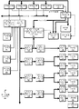
図1は、実施例をその中で実現できるデータ処理システムのブロック図を描いている。データ処理システム100は、システム・バス106に接続する複数のプロセッサ101,102,103,104を含む対称マルチプロセッサ(SMP)システムであり得る。例えば、データ処理システム100は、ネットワーク内でサーバとして実現されたIBM社のeServer(登録商標)であり得る。(eServerは1つの製品であり、e(ロゴ)serverは米国および他の国におけるIBM社の商標である)。あるいは、シングル・プロセッサ・システムが採用されても良い。システム・バス106にメモリ・コントローラ/キャッシュ108も接続されており、これは複数のローカル・メモリ160−163とのインターフェースを提供する。I/Oバス・ブリッジ110は、システム・バス106に接続し、I/Oバス112とのインターフェースを提供する。メモリ・コントローラ/キャッシュ108とI/Oバス・ブリッジ110とは、図示されているように統合され得る。
FIG. 1 depicts a block diagram of a data processing system in which embodiments may be implemented.
データ処理システム100は論理分割されたデータ処理システムである。従って、データ処理システム100は、同時に動作する複数の異種オペレーティング・システム(あるいは単一のオペレーティング・システムの複数のインスタンス)を持つことができる。これらの複数のオペレーティング・システムの各々は、その中で実行する任意の数のソフトウェア・プログラムを持ち得る。データ処理システム100は、異なるPCI I/Oアダプタ120−121,128−129,136、グラフィックス・アダプタ148、およびハードディスク・アダプタ149が異なる論理パーティションに割り当てられ得るように、論理的に分割されている。この場合、グラフィックス・アダプタ148は表示装置(図示されていない)に向けて接続し、ハードディスク・アダプタ149はハードディスク150に接続して制御する。
The
例えば、データ処理システム100は3つの論理パーティションP1,P2,P3に分割されていると想定する。PCI I/Oアダプタ120−121,128−129,136、グラフィックス・アダプタ148、ハードディスク・アダプタ149の各々と、ホスト・プロセッサ101−104の各々と、ローカル・メモリ160−163からのメモリとが3つのパーティションの各々に割り当てられる。これらの例において、メモリ160−163は、デュアル・インライン・メモリ・モジュール(DIMM)の形をとることができる。DIMMは普通はDIMM毎にはパーティションに割り当てられない。代わりに、パーティションは、プラットフォームにより見られるメモリ全体の一部分を得る。例えば、プロセッサ101と、ローカル・メモリ160−163からのメモリの多少の部分と、I/Oアダプタ120,128,129とが論理パーティションP1に割り当てられることができ、プロセッサ102−103と、ローカル・メモリ160−163からのメモリの多少の部分と、PCI I/Oアダプタ121,136とがパーティションP2に割り当てられることができ、プロセッサ104と、ローカル・メモリ160−163からのメモリの多少の部分と、グラフィックス・アダプタ148と、ハードディスク・アダプタ149とが論理パーティションP3に割り当てられることができる。
For example, assume that the
データ処理システム100の中で実行する各オペレーティング・システムは、別々の論理パーティションに割り当てられる。従って、データ処理システム100の中で実行する各オペレーティング・システムは、その論理パーティションの中にあるI/Oユニットだけにアクセスできる。例えば、アドバンスト・インタラクティブ・エグゼクティブ(AIX(登録商標))の1つのインスタンスはパーティションP1の中で実行することができ、AIXオペレーティング・システムの第2インスタンス(イメージ)はパーティションP2の中で実行することができ、Linux(登録商標)またはOS/400(登録商標)オペレーティング・システムは論理パーティションP3の中で動作することができる。(AIXとOS/400とはIBM社の米国および他の国における商標である。Linuxはリーナス・トーバルズの米国および他の国における商標である。)
Each operating system executing within
I/Oバス112に接続されたペリフェラル・コンポーネント・インターコネクト(PCI)ホスト・ブリッジ114は、PCIローカル・バス115とのインターフェースを提供する。数個のPCI入出力アダプタ120−121は、PCI−PCIブリッジ116、PCIバス118、PCIバス119、I/Oスロット170、およびI/Oスロット171を通してPCIバス115に接続する。PCI−PCIブリッジ116は、PCIバス118およびPCIバス119とのインターフェースを提供する。PCI I/Oアダプタ120,121は、それぞれ、I/Oスロット170,171に挿入される。代表的なPCIバス・インプリメンテーションは4個ないし8個のI/Oアダプタ(すなわち、アドイン・コネクタのための拡張スロット)をサポートする。各PCI I/Oアダプタ120−121は、データ処理システム100と、例えば、データ処理システム100のクライアントである他のネットワーク・コンピュータなどの入出力装置との間のインターフェースを提供する。
A peripheral component interconnect (PCI) host bridge 114 connected to the I /
付加的なPCIホスト・ブリッジ122は、付加的なPCIバス123のためのインターフェースを提供する。PCIバス123は複数のPCI I/Oアダプタ128−129に接続する。PCI I/Oアダプタ128−129は、PCI−PCIブリッジ124、PCIバス126、PCIバス127、I/Oスロット172、およびI/Oスロット173を通してPCIバス123に接続する。PCI−PCIブリッジ124は、PCIバス126およびPCIバス127とのインターフェースを提供する。PCI I/Oアダプタ128,129は、それぞれ、I/Oスロット172,173に挿入される。このように、例えばモデムまたはネットワーク・アダプタなどの付加的なI/O装置はPCI I/Oアダプタ128−129の各々を通してサポートされ得る。従って、データ処理システム100は、複数のネットワーク・コンピュータとの接続を可能にする。
Additional PCI host bridge 122 provides an interface for additional PCI bus 123. The PCI bus 123 is connected to a plurality of PCI I / O adapters 128-129. The PCI I / O adapter 128-129 is connected to the PCI bus 123 through the PCI-
メモリマップの(memory mapped)グラフィックス・アダプタ148は、I/Oスロット174に挿入され、PCIバス144、PCI−PCIブリッジ142、PCIバス141、およびPCIホスト・ブリッジ140を通してI/Oバス112に接続する。ハードディスク・アダプタ149はI/Oスロット175に挿入されることができ、これはPCIバス145に接続する。このバスはPCI−PCIブリッジ142に接続し、これはPCIバス141によりPCIホストブリッジ140に接続する。
A memory-mapped
PCIホスト・ブリッジ130は、PCIバス131にI/Oバス112との接続のためのインターフェースを提供する。PCI I/Oアダプタ136はI/Oスロット176に接続し、これはPCIバス133によりPCI−PCIブリッジ132に接続する。PCI−PCIブリッジ132はPCIバス131に接続する。このPCIバスは、また、PCIホスト・ブリッジ130を、サービス・プロセッサ・メールボックス・インターフェース・アンドISAバス・アクセス・パス・スルー・ロジック194とPCI−PCIブリッジ132とに接続する。
The PCI host bridge 130 provides an interface for connection to the I /
サービス・プロセッサ・メールボックス・インターフェース・アンドISAバス・アクセス・パス・スルー・ロジック194は、PCI/ISAブリッジ193に向けられたPCIアクセスを転送する。NVRAM記憶装置192は、ISAバス196に接続する。サービス・プロセッサ135は、そのローカルPCIバス195を通してサービス・プロセッサ・メールボックス・インターフェース・アンドISAバス・アクセス・パス・スルー・ロジック194に接続する。サービス・プロセッサ135は、また、複数のJTAG/I2Cバス134を介してプロセッサ101−104に接続する。JTAG/I2Cバス134は、JTAG/スキャン・バス(IEEE1149.1を参照)とフィリップスI2Cバスとの組み合わせである。
Service processor mailbox interface and ISA bus access pass-through
しかし、その代わりに、JTAG/I2Cバス134は、フィリップスI2CバスだけにあるいはJTAG/スキャン・バスだけに取って代わられても良い。ホスト・プロセッサ101,102,103,104の全てのSP−ATTN信号は、互いに結合しあってサービス・プロセッサ135のインターラプト入力信号となる。サービス・プロセッサ135は、それ自身のローカル・メモリ191を有し、ハードウェアOP−パネル190へのアクセスを有する。
Alternatively, however, the JTAG / I2C bus 134 may be replaced by just a Philips I2C bus or just a JTAG / scan bus. All SP-ATTN signals of the
データ処理システム100が最初にパワー・アップされるとき、サービス・プロセッサ135は、システム(ホスト)プロセッサ101−104、メモリ・コントローラ/キャッシュ108、およびI/Oブリッジ110に質問をするためにJTAG/I2Cバス134を使用する。このステップの完了時に、サービス・プロセッサ135はデータ処理システム100についてのインベントリおよびトポロジ理解を有する。サービス・プロセッサ135は、また、ホスト・プロセッサ101−104、メモリ・コントローラ/キャッシュ108、およびI/Oブリッジ110に質問をすることによって発見された全てのエレメントに対してビルトイン・セルフ・テスト(BIST)、ベーシック・アシュアランス・テスト(BAT)、およびメモリ・テストを実行する。このBIST、BAT、およびメモリ・テストの間に検出された故障についてのエラー情報は、サービス・プロセッサ135により集められて報告される。
When the
BIST、BAT、およびメモリ・テストの間に故障していると分かったエレメントを取り除いた後でもなおシステム・リソースの有意義な/有効なコンフィギュレーションが可能であるならば、データ処理システム100は実行可能なコードをローカル(ホスト)メモリ160−163にロードすることを許される。サービス・プロセッサ135は、その後、ローカル・メモリ160−163にロードされたコードの実行のためにホスト・プロセッサ101−104を解放する。ホスト・プロセッサ101−104がデータ処理システム100内のそれぞれのオペレーティング・システムからのコードを実行している間に、サービス・プロセッサ135はエラーを監視し報告するモードに入る。サービス・プロセッサ135により監視されるアイテムの種類は、例えば、冷却ファンの速度および動作、温度センサ、電源制御装置、並びに、プロセッサ101−104、ローカル・メモリ160−163およびI/Oブリッジ110により報告される回復可能なエラーおよび回復不能のエラーを含む。
サービス・プロセッサ135は、データ処理システム100の全ての監視されるアイテムに関連するエラー情報を保存し報告する。サービス・プロセッサ135は、また、エラーの種類と定められた閾値とに基づいて処置をとる。例えば、サービス・プロセッサ135は、プロセッサのキャッシュ・メモリにおける過度の回復可能なエラーを記録し、これが重大な故障の前兆であると判断することができる。この判断に基づいて、サービス・プロセッサ135は、現在実行中のセッションと将来の初期プログラム・ロード(IPL)のときにコンフィギュレーションから外すためにそのリソースをマークすることができる。IPLは、時には“ブート”または“ブートストラップ”とも称される。
Service processor 135 stores and reports error information associated with all monitored items of
データ処理システム100は、種々の商業的に利用可能なコンピュータ・システムを用いて実現され得る。例えば、データ処理システム100は、IBM社から入手できるIBMのeServer iSeries(IBM社の登録商標)モデル840システムを用いて実現され得る。その様なシステムはOS/400(IBM社の登録商標)オペレーティング・システムを用いて論理的分割をサポートすることができ、これもIBM社から入手できる。
図1に描かれているハードウェアが変わり得ることを当業者は認めるであろう。例えば、図示されているハードウェアに加えてあるいはその代わりに、光ディスク・ドライブなどの他の周辺装置を使用することができる。図示されている例は、実施例に関してアーキテクチャ上の限定を示唆するように意図されてはいない。 Those skilled in the art will appreciate that the hardware depicted in FIG. 1 can vary. For example, other peripheral devices such as optical disk drives can be used in addition to or instead of the hardware shown. The depicted example is not intended to imply architectural limitations with respect to the embodiments.
図2を参照すると、実施例をその中で実現できる代表的な論理分割プラットフォームのブロック図が描かれている。論理分割プラットフォーム200のハードウェアは、例えば、図1のデータ処理システム100として実現され得る。
Referring to FIG. 2, a block diagram of an exemplary logical partitioning platform in which embodiments may be implemented is depicted. The hardware of the logical partitioning platform 200 can be realized as, for example, the
論理分割プラットフォーム200は、分割されたハードウェア230、オペレーティング・システム202,204,206,208、およびプラットフォーム・ファームウェア210を含む。プラットフォーム・ファームウェア210のようなプラットフォーム・ファームウェアは、パーティション管理ファームウェアとしても知られている。オペレーティング・システム202,204,206,208は、単一のオペレーティング・システムの複数のコピー、あるいは論理分割プラットフォーム200上で同時に動作する複数の異種オペレーティング・システムであり得る。これらのオペレーティング・システムはOS/400を用いて実現されることができ、これはハイパーバイザ(Hypervisor)のようなパーティション管理ファームウェアとインターフェースするように設計されている。OS/400(IBM社の登録商標)は、これらの実施例において単に例として用いられるに過ぎない。もちろん、個々のインプリメンテーションにより、AIX(IBM社の登録商標)およびリナックス(Linux)のような他のタイプのオペレーティング・システムを使用しても良い。オペレーティング・システム202,204,206,208はパーティション203,205,207,209に置かれている。
The logical partitioning platform 200 includes partitioned
ハイパーバイザ(Hypervisor)ソフトウェアは、パーティション管理ファームウェア210を実現するために使用され得るソフトウェアの例であり、IBM社から入手できる。ファームウェアは、例えば、読み出し専用メモリ(ROM)、プログラマブルROM(PROM)、消去可能プログラマブルROM(EPROM)、電気的に消去可能なプログラマブルROM(EEPROM)、および不揮発性ランダム・アクセス・メモリ(不揮発性RAM)などの電力無しでその内容を保持するメモリ・チップに格納される“ソフトウェア”である。 Hypervisor software is an example of software that can be used to implement partition management firmware 210 and is available from IBM. Firmware includes, for example, read only memory (ROM), programmable ROM (PROM), erasable programmable ROM (EPROM), electrically erasable programmable ROM (EEPROM), and non-volatile random access memory (non-volatile RAM) "Software" stored in a memory chip that retains its contents without power.
さらに、これらのパーティションはパーティション・ファームウェア211,213,215,217も含む。パーティション・ファームウェア211,213,215,217は、イニシャル・ブート・ストラップ・コード、IEEE−1275スタンダード・オープン・ファームウェア、およびIBM社から入手できるランタイム・アブストラクション・ソフトウェア(RTAS)を用いて実現され得る。パーティション203,205,207,209がインスタンス化されるとき、ブート・ストラップ・コードのコピーがプラットフォーム・ファームウェア210によってパーティション203,205,207,209にロードされる。その後、コントロールはブート・ストラップ・コードに移され、ブート・ストラップ・コードはその後、オープン・ファームウェアとRTASとをロードする。その後、パーティションに関連付けられあるいは割り当てられているプロセッサは、パーティション・ファームウェアを実行するためにパーティションのメモリにディスパッチされる。 In addition, these partitions also include partition firmware 211, 213, 215, 217. Partition firmware 211, 213, 215, 217 may be implemented using initial bootstrap code, IEEE-1275 standard open firmware, and runtime abstraction software (RTAS) available from IBM. When partitions 203, 205, 207, 209 are instantiated, a copy of the bootstrap code is loaded into partitions 203, 205, 207, 209 by platform firmware 210. Control is then transferred to the bootstrap code, which then loads the open firmware and RTAS. Thereafter, the processors associated with or assigned to the partition are dispatched to the partition's memory to execute the partition firmware.
分割されたハードウェア230は、複数のプロセッサ232−238と、複数のシステム・メモリ・ユニット240−246と、複数の入出力(I/O)アダプタ248−262と、記憶装置270とを含む。プロセッサ232−238、メモリ・ユニット240−246、NVRAM記憶装置298、およびI/Oアダプタ248−262の各々は論理分割プラットフォーム200内の複数のパーティションのうちの1つに割り当てられることができ、その各々はオペレーティング・システム202,204,206,208のうちの1つに対応する。
The divided
パーティション管理ファームウェア210は、論理分割プラットフォーム200のパーティショニングを引き起こし実施するべくパーティション203,205,207,209のために幾つかの機能およびサービスを実行する。パーティション管理ファームウェア210は、下に存在するハードウェアと同一のファームウェア実現される仮想マシンである。パーティション管理ファームウェア210は、論理分割プラットフォーム200の全てのハードウェア・リソースを仮想化することによって独立のOSイメージ202,204,206,208の同時実行を可能にする。
Partition management firmware 210 performs several functions and services for partitions 203, 205, 207, and 209 to cause and implement partitioning of logical partitioning platform 200. The partition management firmware 210 is a virtual machine implemented with the same firmware as the underlying hardware. The partition management firmware 210 enables simultaneous execution of
サービス・プロセッサ290は、パーティションにおけるプラットフォーム・エラーの処理などの種々のサービスを提供するために使用され得る。これらのサービスは、IBM社のようなベンダーにエラーを報告するためにサービス・エージェントとして行動することもできる。種々のパーティションの動作は、ハードウェア管理コンソール280のようなハードウェア管理コンソールを通して制御され得る。ハードウェア管理コンソール280は1つの独立のデータ処理システムであって、これからシステム管理者は種々のパーティションへのリソースの再割り当てを含む種々の機能を実行することができる。
Service processor 290 may be used to provide various services such as handling platform errors in partitions. These services can also act as service agents to report errors to vendors such as IBM. The operation of the various partitions can be controlled through a hardware management console, such as
図1−2のハードウェアは、インプリメンテーションにより変わり得る。図1−2に示されている或るハードウェアに加えてあるいはその代わりに、フラッシュ・メモリ、同等の不揮発性メモリ、あるいは光ディスク・ドライブなどの他の内部ハードウェアまたは周辺装置が使用され得る。実施例の1つのインプリメンテーションは、実施例の範囲から逸脱せずにパーティションを管理するために代わりのアーキテクチャを使用することもできる。 The hardware of FIGS. 1-2 may vary depending on the implementation. Other internal hardware or peripheral devices such as flash memory, equivalent non-volatile memory, or optical disk drives may be used in addition to or instead of certain hardware shown in FIGS. 1-2. One implementation of the embodiment may use an alternative architecture to manage the partitions without departing from the scope of the embodiment.
図1−2に示されている例と上記の例とは、アーキテクチャに関する限定事項を示唆するように意図されてはいない。例えば、論理分割プラットフォーム200は、実施例の範囲内で実施例を実施するために非分割型データ処理システムと置き換えられても良い。さらに、その非分割型データ処理システムは、PDAの形をとるほかに、タブレット・コンピュータ、ラップトップ・コンピュータまたは電話装置であり得る。代わりのデータ処理システムのこれらの例は、マルチパスI/Oコンフィギュレーションと同様に動作し得る複数のネットワーク・アダプタまたは無線通信装置を含むことができる。従って、実施例は、この開示に記載されている仕方で、これらのデータ処理システムに応用され得る。 The example shown in FIG. 1-2 and the above example are not intended to imply architectural limitations. For example, the logical partitioning platform 200 may be replaced with a non-partitioned data processing system to implement embodiments within the scope of the embodiments. Further, the non-split data processing system may be a tablet computer, laptop computer or telephone device in addition to taking the form of a PDA. These examples of alternative data processing systems may include multiple network adapters or wireless communication devices that may operate similarly to multipath I / O configurations. Accordingly, embodiments can be applied to these data processing systems in the manner described in this disclosure.
図3を参照すると、この図は、一実施例に従ってマルチパス・データ通信を監視することのブロック図を描いている。 Referring to FIG. 3, this figure depicts a block diagram of monitoring multipath data communication according to one embodiment.
データ処理システム300は、図2のパーティション203のようなパーティションであり得る。あるいは、データ処理システム300は、図2の論理分割プラットフォーム200全体であり得る。あるいは、データ処理システム300は、マルチパス・データ通信を使用するクライアントまたはサーバ・データ処理システムのような任意タイプのコンピュータにおいて実現され得る。 Data processing system 300 may be a partition such as partition 203 of FIG. Alternatively, the data processing system 300 may be the entire logical partitioning platform 200 of FIG. Alternatively, data processing system 300 may be implemented in any type of computer, such as a client or server data processing system that uses multipath data communications.
データ処理システム300は、イーサネット(登録商標)でのデータ通信のための物理的ネットワーク・アダプタのような、数個のI/O装置を含むことができる。アダプタ302,304,306は、その様なI/O装置の例である。データ処理システム300は、アダプタ302,304,306の代わりとなるかあるいはこれらのアダプタと組み合わされるI/O装置として、無線トランシーバのような、無線通信に使用できる装置を含むこともできる。 The data processing system 300 can include several I / O devices, such as a physical network adapter for data communication over Ethernet. Adapters 302, 304, and 306 are examples of such I / O devices. The data processing system 300 can also include devices that can be used for wireless communication, such as wireless transceivers, as I / O devices that can replace or be combined with the adapters 302, 304, 306.
データ処理システム300は、さらにオペレーティング・システム308を含む。1つ以上のアプリケーション310がデータ処理システム300上で実行できる。 Data processing system 300 further includes an operating system 308. One or more applications 310 can execute on the data processing system 300.
データ処理システム300は、マルチパス・データ通信コンフィギュレーションでデータ記憶装置312と通信することができる。データ記憶装置312も数個のI/O装置を含むことができる。アダプタ314,316,318,320は、その様なI/O装置の例であり、ネットワーク・アダプタ、無線トランシーバ、またはその組み合わせの形をとることができる。アダプタ314,316,318,320は、データ記憶装置312を許容し、あるいは、数個のデータ・ネットワークを介するデータ処理システム300および他のデータ処理システムとのデータ通信に参加する。
The data processing system 300 can communicate with the
この図例では、データ処理システム300は、マルチパス・データ通信を用いてデータ記憶装置312と通信する。マルチパス・データ通信は、アダプタ302,304,306をそれぞれアダプタ314,316,320と通信するように設定することによって確立される。
In this illustrative example, data processing system 300 communicates with
一実施例では、監視アプリケーション322は、データ処理システム300のアダプタ302,304,306の使用率を監視する。監視アプリケーション322は、さらにオペレーティング・システム308からのデータ通信容量についての要求を監視することができる。 In one embodiment, the monitoring application 322 monitors the usage rate of the adapters 302, 304, 306 of the data processing system 300. The monitoring application 322 can further monitor requests for data communication capacity from the operating system 308.
図4を参照すると、この図は一実施例に従う監視アプリケーションのブロック図を描いている。監視アプリケーション400は、図3の監視アプリケーション322として実現され得る。 Referring to FIG. 4, this figure depicts a block diagram of a monitoring application according to one embodiment. The monitoring application 400 can be realized as the monitoring application 322 of FIG.
監視アプリケーション400は、コンフィギュレーション・コンポーネント402を含むことができる。コンフィギュレーション・コンポーネント402は、例えば、ユーザが監視アプリケーション400の動作を設定することを可能にする。他の例として、コンフィギュレーション・コンポーネント402は、図3のデータ処理システム300のような、監視アプリケーション400がそこで実行できるところのデータ処理システムが、監視アプリケーション400がそのもとで実行できるところの基準、条件、あるいはパラメータを確立することを可能にすることができる。 The monitoring application 400 can include a configuration component 402. Configuration component 402 allows, for example, a user to configure the operation of monitoring application 400. As another example, the configuration component 402 may be a criteria for a data processing system on which the monitoring application 400 can run, such as the data processing system 300 of FIG. , Conditions, or parameters can be established.
監視アプリケーション400は、ルール406を処理することのできるルール・ベース・エンジン404をさらに含むことができる。一実施態様では、ルール406は、コンフィギュレーション・コンポーネント402に記載されているコンフィギュレーションに由来し得る。例えば、ユーザは、コンフィギュレーション・コンポーネント402において、任意の時点でアクティブな物理的ネットワーク・アダプタの総数が2未満ではあり得ないと指定することができる。コンフィギュレーション・コンポーネント402からのこの指定は、ルール・ベース・エンジン404が実行できるルール406中のルールに変換され得る。 The monitoring application 400 can further include a rule base engine 404 that can process the rules 406. In one implementation, the rules 406 can be derived from the configuration described in the configuration component 402. For example, the user may specify in the configuration component 402 that the total number of active physical network adapters at any given time cannot be less than two. This designation from the configuration component 402 can be translated into rules in rules 406 that the rule base engine 404 can execute.
他の1つの実施態様では、ルール406の中のルールは、監視アプリケーション400がそこで実行できるところのデータ処理システムにおけるシステム全体にわたるポリシーに由来し、該ポリシーを前身とし、該ポリシーに起因し、該ポリシーに依拠し、あるいは該ポリシーに別様に基づくことができる。例えば、システム・ポリシーは、1つのネットワーク・アダプタの使用率が5分間以上にわたって80パーセントを上回ることはできないと指定することができる。このシステム・ポリシーは、ルール・ベース・エンジン404が実行できるルール406の中のルールに変換され得る。 In another embodiment, the rules in rule 406 are derived from a system-wide policy in the data processing system where monitoring application 400 can execute, predecessor of the policy, attributed to the policy, You can rely on or otherwise depend on the policy. For example, a system policy may specify that the usage of one network adapter cannot exceed 80 percent for more than 5 minutes. This system policy may be translated into rules in rules 406 that can be executed by rule base engine 404.
さらに、ルール406の中のルールは、どの様にデータ通信を1つのI/O装置から他の1つのI/O装置に移すことによって1つのI/O装置の使用率を減少させて他のI/O装置の使用率を増大させるかを記述することができる。 In addition, the rules in rule 406 reduce the usage rate of one I / O device by moving data communication from one I / O device to another I / O device. Whether to increase the usage rate of the I / O device can be described.
ルール406の中のルールは、パワー・オフされたI/O装置をどの様な状況下でどんな手続きを用いて再びパワー・オンできるかを指定することもできる。ルール406の中のルールは、オペレーティング・システムがより大きなデータ通信容量あるいはより高度のデータ通信可用性を要求するときに追加のI/O装置をパワー・オンし利用可能にするためにとるべきステップを指定することができる。ルール406の中のルールは、どの様に増大したデータ通信負荷を予測し、増大したデータ通信ニーズが生じる前にI/O装置を予測的にパワー・オンするかを指定することもできる。 The rules in rule 406 can also specify under what circumstances and under what circumstances can be used to power on the I / O device again. The rules in rule 406 take steps to be taken to power on and make available additional I / O devices when the operating system requires greater data communication capacity or higher data communication availability. Can be specified. The rules in rule 406 can also specify how to predict increased data communication load and predictively power on I / O devices before increased data communication needs arise.
ルール406の中のルールの例は、ここで記述を明瞭にするために記載されたに過ぎなくて、実施例を限定するものではない。他の多くのタイプの処置とルールの構成とがこの開示から明らかとなろう。その様な付加的なルールは、実施例の範囲内で考慮される。さらに、コンフィギュレーション・コンポーネント402、ルール・ベース・エンジン404、およびルール406の関連相互作用も、明瞭性を目的として例として記載されているに過ぎなくて、それにより実施例に関して何らかの限定を課すものではない。実施例の特定のインプリメンテーションは、実施例の範囲から逸脱せずに代替コンポーネントを通して同様の機能性を達成することができる。 The example rules in rule 406 are provided here for clarity only and are not intended to limit the embodiments. Many other types of actions and rule configurations will be apparent from this disclosure. Such additional rules are considered within the scope of the embodiments. In addition, the associated interaction of the configuration component 402, the rule base engine 404, and the rule 406 is also described by way of example for purposes of clarity and thereby imposes some limitations with respect to the embodiment. is not. Certain implementations of the embodiments can achieve similar functionality through alternative components without departing from the scope of the embodiments.
図の説明に戻ると、監視アプリケーション400はパワー・コントロール・ロジック408をさらに含むことができる。パワー・コントロール・ロジック408は、図3のアダプタ302,304、あるいは306のいずれかなどの特定のI/O装置をオンあるいはオフにする命令をルール・ベース・エンジン404から受け取ることができる。さらに、パワー・コントロール・ロジック408は、特定のI/O装置の使用率を、そのI/O装置をパワー・オフする前に減少させるために、一定のデータ通信を1つのI/O装置から他のI/O装置に移すために一定のステップを実行するように構成され得る。 Returning to the description of the figure, the monitoring application 400 may further include power control logic 408. The power control logic 408 may receive an instruction from the rule base engine 404 to turn on or off a particular I / O device such as any of the adapters 302, 304, or 306 of FIG. In addition, the power control logic 408 allows certain data communication from one I / O device to reduce the utilization of a particular I / O device before powering off that I / O device. It may be configured to perform certain steps for transfer to other I / O devices.
監視アプリケーション400の図示されているコンポーネントは網羅的ではない。図示されているコンポーネントは、1つの実施例の機能性を記述するために選択されたのであって、実施例についての限定事項として選択されたのではない。特定のインプリメンテーションは、実施例の範囲から逸脱せずに監視アプリケーション400に追加のあるいは異なるコンポーネントを含むことができる。 The illustrated components of the monitoring application 400 are not exhaustive. The components shown are chosen to describe the functionality of one embodiment, not as a limitation on the embodiment. Certain implementations may include additional or different components to the monitoring application 400 without departing from the scope of the embodiments.
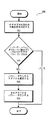
図5を参照すると、この図は一実施例に従ってマルチパス・データ通信コンフィギュレーションにおいてエネルギーを節約するプロセスのフローチャートを描いている。プロセス500は、図4の監視アプリケーション400において実行され得る。さらに、プロセス500は、単なる例としてのI/O装置のアダプタ実施態様に関して記載される。プロセス500で記述されるアダプタは実施例を限定するものではなく、プロセス500と関連して任意の適切なI/O装置が使用され得る。
Referring to FIG. 5, this figure depicts a flow chart of a process for saving energy in a multipath data communication configuration according to one embodiment.
プロセス500は、マルチパス・データ通信コンフィギュレーションにおいて設定されている各アダプタの現在の作業負荷または使用率を判定することから始まる(ステップ502)。プロセス500は、コンフィギュレーションまたはルールに違反せずにいずれかのアダプタをパワー・オフできるか否かを判定する(ステップ504)。ステップ504の判定を行うことと関連して、プロセス500は、上記のようにアダプタを解放するために作業負荷を1つのアダプタから他のアダプタに移す追加のステップを実行することができる。
もしプロセス500が1つのアダプタをパワー・オフできると判定したならば(ステップ504の“はい”経路)、プロセス500はパワー・ダウンに関して複数のアダプタが候補であると判定することができる。プロセス500は、パワー・ダウンする1つのアダプタを選択する(ステップ506)。
If
デバイスをパワー・ダウンするということは、その装置を完全にまたは部分的にオフにすることである。例えば、或る装置は、その装置への相当の電力がオフにされてその装置の相当の機能が停止しているときにも、なお電力を引くことができる。装置のパワー・ダウン・モードは、装置がパワー・ダウンされているときのその装置の状態である。逆に、装置をパワー・アップするということは、装置の相当の機能を使用可能にするためにその装置に電力を供給することである。装置のパワー・アップ・モードは、その装置の機能の相当の部分を実行するために充分な電力を受け取っている場合のその装置の状態のことである。 To power down a device is to turn it off completely or partially. For example, a device can still draw power when significant power to the device is turned off and significant functionality of the device is stopped. A device's power down mode is the state of the device when the device is powered down. Conversely, to power up a device is to supply power to the device in order to enable considerable functionality of the device. A device's power-up mode is the state of the device when it receives enough power to perform a significant portion of the device's function.
プロセス500は、選択されたアダプタをパワー・ダウンする(ステップ508)。プロセス500は、その後、終了する。アダプタがパワー・オフされ得ないとプロセス500が判定したならば(ステップ504の“いいえ”経路)、プロセス500はその後にも終了する。
Process 500 powers down the selected adapter (step 508).
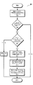
図6を参照すると、この図は1つの実施例に従ってI/O装置をリスタートさせるプロセスのフローチャートを描いている。プロセス600は、図4の監視アプリケーション400で実行され得る。図5の場合と同じく、プロセス600も単に例証を目的としてI/O装置の例としてアダプタを用いる。 Referring to FIG. 6, this figure depicts a flowchart of a process for restarting an I / O device according to one embodiment. Process 600 may be performed by monitoring application 400 of FIG. As in FIG. 5, process 600 uses an adapter as an example of an I / O device for illustrative purposes only.
プロセス600は、追加のアダプタに対するニーズを判定することから始まる(ステップ602)。プロセス600は、図7Aおよび7Bに描かれているように少なくとも2つの仕方で該ニーズを判定することができる。 Process 600 begins with determining the need for additional adapters (step 602). Process 600 can determine the need in at least two ways as depicted in FIGS. 7A and 7B.
追加のアダプタに対するニーズが存在するかあるいは所定間隔の内に発生しそうであるとプロセス600がステップ602で判定したとき、プロセス600はパワー・ダウン・モードになっているアダプタがあるか否かを判定する(ステップ604)。一実施態様では、その待ち時間がステップ602の判定の時間と該ニーズが発生するべき時間との間の間隔より短いアダプタがパワー・ダウン・モードで利用できるか否かを判定することができる。
When process 600 determines in
プロセス600は、適切なアダプタを特定すると(ステップ604の“はい”経路)、そのアダプタをパワー・アップする(ステップ606)。プロセス600は、そのアダプタをマルチパス・データ通信のために利用可能にする(ステップ608)。プロセス600はその後、終了する。 Once process 600 identifies an appropriate adapter (the “yes” path of step 604), it powers up the adapter (step 606). Process 600 makes the adapter available for multipath data communication (step 608). Process 600 then ends.
もし増大したデータ通信に対するニーズが発生したかあるいは発生しそうであり、パワー・ダウン・モードの適切なアダプタが利用できなければ(ステップ604の“いいえ”経路)、プロセス600はユーザに通知する(ステップ610)。プロセス600はその後、終了する。一実施態様では、プロセス600はステップ610でシステムに通知することができる。他の1つの実施態様では、プロセス600はステップ610でメッセージを記録することができる。プロセス600は、実施例の範囲から逸脱せずに、描かれているステップ610に代わる任意の適切な選択肢をステップ610で実行することができる。
If the need for increased data communication has occurred or is likely to occur and an appropriate adapter in power down mode is not available ("No" path of step 604), process 600 notifies the user (step 610). Process 600 then ends. In one implementation, process 600 may notify the system at
図7Aを参照すると、この図は一実施例に従って増大したデータ通信に対するニーズを判定する一プロセスのフローチャートを描いている。プロセス700は、図6のステップ602として実行され得る。
Referring to FIG. 7A, this figure depicts a flowchart of a process for determining the need for increased data communication according to one embodiment.
プロセス700は、追加のアダプタを求めるリクエストを受け取ることができる(ステップ702)。例えば、ステップ702を実行するとき、プロセス700は、追加のアダプタをマルチパスI/Oコンフィギュレーションに加えることによって満たされ得る増大したデータ通信容量を該オペレーティング・システムが必要とするという命令を該オペレーティング・システムから受け取ることができる。プロセス700は図6のプロセス600のステップ604に進むことができる(エントリ・ポイントA)。プロセス700は、その後にプロセス600が終了するときに終了する。
図7Bを参照すると、この図は一実施例に従って増大したデータ通信に対するニーズを判定する他の一プロセスのフローチャートを描いている。プロセス720は、図6のステップ602として実行され得る。
Referring to FIG. 7B, this figure depicts a flowchart of another process for determining the need for increased data communication according to one embodiment.
プロセス720は、追加のアダプタに対するニーズを特定することができる(ステップ722)。一例として、ステップ722を実行するとき、プロセス700は、マルチパスI/Oコンフィギュレーションに追加のアダプタを加えることによって満たされ得る将来の或る時点での増大したニーズを予報あるいは予測することができる。
一実施態様では、その様な予測のために、プロセス720は、アダプタをパワー・アップすることについての待ち時間を考慮に入れることができる。例えば、特定のアダプタをパワー・オンすることと、そのアダプタがデータ通信に利用され得るようになることとの間に5秒の時間が経過し得る。I/O装置をパワー・オンした時点から該I/O装置が利用可能になる時点までのその様な時間間隔は、そのI/O装置の待ち時間と称される。プロセス720は、いずれかのパワー・ダウンされているアダプタの待ち時間のうちに追加のアダプタに対するニーズが発生しそうであるか否かを予測するとき、ステップ722でその様な待ち時間を考慮することができる。図8のプロセス800は、待ち時間を含む予測プロセスの一例を詳しく示す。
In one implementation, for such a prediction,
プロセス720は、図6のプロセス600のステップ604に進むことができる(エントリ・ポイントA)。プロセス720は、その後にプロセス600が終了するときに終了する。プロセス700および720も、単なる例証の目的でI/O装置の例としてアダプタを用いている。
図8を参照すると、この図は、一実施例に従ってI/O装置待ち時間を用いてマルチパス・データ通信作業負荷を管理するプセセスのフローチャートを描いている。プロセス800は、図7Bのステップ722と図6のプロセス600との組み合わせとして実行され得る。プロセス800も、単なる例証の目的でI/O装置の例としてアダプタを用いる。プロセス800は、実施例の範囲内で任意のタイプのI/O装置で実行され得る。
Referring to FIG. 8, this figure depicts a flowchart of a process for managing a multipath data communication workload using I / O device latency according to one embodiment.
プロセス800は、始めに、将来の時点“T”における作業負荷予測を受け取るかあるいは判定する(ステップ802)。プロセス800は、時点Tにおいて追加のアダプタをマルチパス・コンフィギュレーションに加えなければならないかも知れないか否かを判定する(ステップ804)。もしプロセス800が追加のアダプタが必要でないかも知れないと判定したならば(ステップ804の“いいえ”経路)、プロセス800は終了することができる。
しかし、もし追加のアダプタが加えられなければならないかも知れないとプロセス800が判定すれば(ステップ804の“はい”経路)、プロセス800はパワー・ダウン・モードのアダプタが利用できるか否かを判定する(ステップ806)。パワー・ダウン・モードのアダプタが利用可能ではないけれども1つ必要であるとプロセス800が判定したならば(ステップ806の“いいえ”経路)、プロセス800は通知を行うかあるいは図6のステップ610に類似する他の行動をとることができる(ステップ808)。プロセス800は、その後に終了することができる。
However, if
もしパワー・ダウン・モードのアダプタが利用可能であるとプロセス800が判定したならば(ステップ806の“はい”経路)、プロセス800は、そのアダプタのパワー・アップ待ち時間を判定することができる(ステップ810)。プロセス800は、ステップ806で、ステップ802のニーズの時点が到来する前にその待ち時間が経過し得るアダプタだけを選択できる。利用可能なアダプタの全てがその時点までに完全に経過し得ない待ち時間を有するならば、プロセス800は、あたかもニーズを満たすために利用できるアダプタが無いかのようにステップ806の“いいえ”経路を進むことができる。
If
プロセス800は、Tマイナス待ち時間より遅くない時点で該アダプタをパワー・アップすることができる(ステップ812)。プロセス800は、時点Tまたはそれより前に該アダプタをマルチパス・データ通信のために利用できるようにする(ステップ814)。プロセス800は、その後に終了する。
ブロック図中のコンポーネントと、上記フローチャートのステップとは単に例として記述されたに過ぎない。該コンポーネントおよびステップは、説明を明瞭にするために選択されたのであって、実施例に関して限定をするものではない。例えば、具体的なインプリメンテーションは、実施例の範囲から逸脱せずに該コンポーネントまたはステップのいずれかを組み合わせ、省略し、さらに細分し、改変し、増大させ、減少させ、あるいは択一的に実施することができる。さらに、上記プロセスのステップは、実施例の範囲内で異なる順序で実行されても良い。 The components in the block diagram and the steps in the flowchart are described merely as examples. The components and steps have been chosen for clarity of explanation and are not limiting with respect to the embodiments. For example, a specific implementation may combine, omit, further subdivide, modify, increase, decrease, or alternatively any of the components or steps without departing from the scope of the embodiments. Can be implemented. Furthermore, the steps of the above process may be performed in a different order within the scope of the embodiments.
この様に、マルチパス・データ通信においてエネルギーを節約するために実施例においてコンピュータ実行される方法、装置およびコンピュータ・プログラム製品が提供される。実施例を用いて、データ処理システムは、マルチパス・データ通信向けに構成されたI/O装置を選択的にパワー・オンしパワー・オフすることができる。データ処理システムは、データ通信スループットまたは信頼性に悪影響を及ぼさずにエネルギーを節約するためにデータ通信作業負荷を動作中のI/O装置に再分配し、また1つ以上のI/O装置をパワー・オフし得るであろう。 Thus, a computer-implemented method, apparatus and computer program product are provided in embodiments to conserve energy in multipath data communications. Using embodiments, the data processing system can selectively power on and power off I / O devices configured for multipath data communications. The data processing system redistributes the data communication workload to active I / O devices and saves one or more I / O devices to save energy without adversely affecting data communication throughput or reliability. Could power off.
実施例は、変化するデータ通信ニーズに応じて、パワー・ダウンされているI/O装置を柔軟に再使用可能にする。或る実施態様は、データ通信のスループットまたは信頼性における切迫した増大についての予測に基づいてI/O装置をパワー・アップするために使用され得る。 Embodiments allow flexible reuse of powered down I / O devices in response to changing data communication needs. Certain embodiments may be used to power up an I / O device based on a prediction for an impending increase in data communication throughput or reliability.
或るインプリメンテーションでは、実施例は、一定の状況下で電力を節約するために1つのI/O装置以外の全てのI/O装置をオフにすることを可能にすることができる。他のインプリメンテーションでは、実施例は、冗長性を維持するために少なくとも2つのI/O装置を除いて他の全てのI/O装置をオフにすることを可能にすることができる。実施例の1つの特定のインプリメンテーションは、任意の時点で作動状態に留まっていなければならないI/O装置の閾値個数をセットすることができる。この条件と、他のコンフィギュレーション関連条件とは、実施例においてルールとルール・ベース・エンジンとを用いて実施され得る。 In some implementations, embodiments may allow all I / O devices other than one I / O device to be turned off to save power under certain circumstances. In other implementations, embodiments may allow all other I / O devices to be turned off except for at least two I / O devices to maintain redundancy. One particular implementation of the embodiment can set a threshold number of I / O devices that must remain operational at any point in time. This condition and other configuration-related conditions can be implemented using rules and a rule base engine in an embodiment.
本発明は、完全にハードウェアの実施態様、完全にソフトウェアの実施態様、あるいはハードウェア要素とソフトウェア要素との両方を含む実施態様の形をとることができる。1つの好ましい実施態様では、本発明はソフトウェアで実施され、それはファームウェア、常駐ソフトウェア、マイクロコードを含むけれども、それらに限定されない。 The invention can take the form of an entirely hardware embodiment, an entirely software embodiment or an embodiment containing both hardware and software elements. In one preferred embodiment, the present invention is implemented in software, which includes but is not limited to firmware, resident software, microcode.
さらに、本発明は、コンピュータまたは任意の命令実行システムによりあるいはそれらと関連して使用されるプログラム・コードを提供するコンピュータ使用可能なまたはコンピュータ可読の媒体からアクセスできるコンピュータ・プログラム製品の形をとることができる。この記述の目的上、コンピュータ使用可能なまたはコンピュータ可読の媒体は、命令実行システム、装置、またはデバイスにより、あるいはそれらと関連して、使用されるプログラムを包含し、記憶し、伝達し、伝播し、あるいは運ぶことのできる任意の有形装置であり得る。 Furthermore, the present invention takes the form of a computer program product accessible from a computer-usable or computer-readable medium that provides program code for use by or in connection with a computer or any instruction execution system. Can do. For the purposes of this description, a computer-usable or computer-readable medium encompasses, stores, communicates, and propagates programs used by or in connection with an instruction execution system, apparatus, or device. Or any tangible device that can be carried.
該媒体は、電子、磁気、光学、電磁、赤外線、あるいは半導体のシステム(あるいは装置またはデバイス)または伝播媒体であり得る。コンピュータ可読媒体の例は、半導体または固体メモリ、磁気テープ、取り外し可能なコンピュータ・ディスケット、ランダム・アクセス・メモリ(RAM)、読み出し専用メモリ(ROM)、リジッド磁気ディスクおよび光ディスクを含む。光ディスクの現在の例は、コンパクト・ディスク−読み出し専用メモリ(CD−ROM)、コンパクト・ディスク−読み出し/書き込み(CD−R/W)およびDVDを含む。 The medium can be an electronic, magnetic, optical, electromagnetic, infrared, or semiconductor system (or apparatus or device) or a propagation medium. Examples of computer readable media include semiconductor or solid state memory, magnetic tape, removable computer diskette, random access memory (RAM), read only memory (ROM), rigid magnetic disk and optical disk. Current examples of optical disks include compact disk-read only memory (CD-ROM), compact disk-read / write (CD-R / W) and DVD.
さらに、コンピュータ可読のプログラム・コードがコンピュータ上で実行されるときに、このコンピュータ可読のプログラム・コードの実行が該コンピュータに他のコンピュータ可読プログラム・コードを通信リンクを介して送信させるように、コンピュータ記憶媒体はコンピュータ可読のプログラム・コードを収容しあるいは記憶することができる。この通信リンクは、例えば限定無しで、物理的なまたは無線の媒体を使用することができる。 Further, when the computer readable program code is executed on a computer, the computer causes execution of the computer readable program code to transmit the other computer readable program code over a communication link. The storage medium may contain or store computer readable program code. This communication link may use physical or wireless media, for example without limitation.
プログラム・コードを記憶し、かつ、または、実行するために適するデータ処理システムは、メモリ素子に直接にあるいはシステム・バスを通して間接的に結合される少なくとも1つのプロセッサを含むであろう。メモリ素子は、プログラム・コードの現実の実行時に使用されるローカル・メモリ、大容量記憶装置、および、実行中にコードが大容量記憶装置から取り出されなければならない回数を減らすために少なくとも多少のプログラム・コードの一時記憶を提供するキャッシュ・メモリを含み得る。 A data processing system suitable for storing and / or executing program code will include at least one processor coupled directly to the memory elements or indirectly through a system bus. The memory element is a local memory used during the actual execution of program code, a mass storage device, and at least some programs to reduce the number of times code must be fetched from the mass storage device during execution. It may include a cache memory that provides temporary storage of code.
データ処理システムは、サーバ・データ処理システムまたはクライアント・データ処理システムとして動作することができる。サーバ・データ処理システムおよびクライアント・データ処理システムは、コンピュータ可読であるなどしてコンピュータ使用可能であるデータ記憶媒体を含むことができる。サーバ・データ処理システムと関連付けられたデータ記憶媒体は、コンピュータ使用可能なコードを含むことができる。クライアント・データ処理システムは、そのコンピュータ使用可能なコードを、そのクライアント・データ処理システムと関連付けられたデータ記憶媒体に格納し、あるいは該クライアント・データ処理システムで使用するなどのために、ダウンロードすることができる。サーバ・データ処理システムは、コンピュータ使用可能なコードをクライアント・データ処理システムから同様にアップロードすることができる。実施例のコンピュータ使用可能なプログラム製品実施態様に由来するコンピュータ使用可能なコードは、この様にしてサーバ・データ処理システムとクライアント・データ処理システムとを用いてアップロードまたはダウンロードされ得る。 The data processing system can operate as a server data processing system or a client data processing system. Server data processing systems and client data processing systems may include data storage media that are computer usable, such as computer readable. The data storage medium associated with the server data processing system can include computer usable code. The client data processing system stores its computer usable code in a data storage medium associated with the client data processing system or downloads it for use in the client data processing system, etc. Can do. The server data processing system can similarly upload computer usable code from the client data processing system. Computer usable code from the example computer usable program product implementation may be uploaded or downloaded in this manner using a server data processing system and a client data processing system.
入出力あるいはI/O装置(キーボード、ディスプレイ、ポインティング・デバイスなどを含むが、これらに限定されない)は、直接に、あるいは介在するI/Oコントローラを通して、システムに結合され得る。 Input / output or I / O devices (including but not limited to keyboards, displays, pointing devices, etc.) can be coupled to the system either directly or through intervening I / O controllers.
データ処理システムが、介在する構内ネットワークまたは公衆網を通して他のデータ処理システムまたはリモート・プリンタまたは記憶装置に結合され得るようにネットワーク・アダプタをシステムに結合させることもできる。モデム、ケーブル・モデムおよびイーサネット(登録商標)・カードは、ほんの幾つかの現在利用可能なタイプのネットワーク・アダプタである。 Network adapters can also be coupled to the system so that the data processing system can be coupled to other data processing systems or remote printers or storage devices through intervening local or public networks. Modems, cable modems and Ethernet cards are just a few currently available types of network adapters.
本発明の記述は、例証および記述の目的で提示されており、網羅的であることや、開示された形の発明に限定されることは意図されていない。多くの改変および変形が当業者にとっては明らかであろう。実施態様は、本発明の原理、実際的応用を説明し、意図されている特定の用途に適する種々の改変を伴う種々の実施態様を目的として他の当業者が本発明を理解できるように、選択され記述された。 The description of the present invention has been presented for purposes of illustration and description, and is not intended to be exhaustive or limited to the invention in the form disclosed. Many modifications and variations will be apparent to practitioners skilled in this art. The embodiments are illustrative of the principles, practical applications of the invention, and will enable others skilled in the art to understand the invention for various embodiments with various modifications suitable for the particular intended use. Selected and described.
Claims (20)
複数のI/O装置の各々の現在の使用率を判定することと、
前記複数のI/O装置のうちのI/O装置がルールに違反せずにパワー・ダウンされ得るか否かを判定し、違反の表示を形成することと、
前記違反の表示が偽であることに応答して前記I/O装置をパワー・ダウンすることと、
を含む、前記コンピュータ実行される方法。 A computer-implemented method for energy saving in multipath data communication comprising:
Determining the current utilization of each of the plurality of I / O devices;
Determining whether an I / O device of the plurality of I / O devices can be powered down without violating a rule, and forming a violation indication;
Powering down the I / O device in response to the indication of the violation being false;
A computer-implemented method comprising:
前記I/O装置を特定することと、
前記I/O装置をパワー・アップすることと、
前記I/O装置をマルチパスI/Oコンフィギュレーションのために利用可能にすることと、
をさらに含む、請求項1に記載のコンピュータ実行される方法。 Determining whether additional I / O devices are required in a multipath I / O configuration and forming a power-up indication;
Identifying the I / O device;
Powering up the I / O device;
Making the I / O device available for multipath I / O configuration;
The computer-implemented method of claim 1, further comprising:
前記追加のI/O装置が必要とされる前記時間より前に前記I/O装置の待ち時間が経過し得るか否かを判定し、待ち時間の表示を形成することと、
前記待ち時間の表示が真であることに応答して前記I/O装置をパワー・オンすることと、
をさらに含む、請求項2に記載のコンピュータ実行される方法。 Determining the time required for the additional I / O device;
Determining whether the waiting time of the I / O device can elapse before the time when the additional I / O device is needed, and forming a display of the waiting time;
Powering on the I / O device in response to the indication of the latency being true;
The computer-implemented method of claim 2, further comprising:
ルールに基づいて、前記I/O装置をパワー・ダウンするロジックを作動させること、
をさらに含む、請求項1に記載のコンピュータ実行される方法。 The power down is
Activating logic to power down the I / O device based on rules;
The computer-implemented method of claim 1, further comprising:
複数のI/O装置の各々の現在の使用率を判定するためのコンピュータ使用可能なコードと、
前記複数のI/O装置のうちのI/O装置がルールに違反せずにパワー・ダウンされ得るか否かを判定し、違反の表示を形成するためのコンピュータ使用可能なコードと、
前記違反の表示が偽であることに応答して前記I/O装置をパワー・ダウンするためのコンピュータ使用可能なコードであって、ルールに基づいて、前記I/O装置をパワー・ダウンするロジックを作動させるためのコンピュータ使用可能なコードを含む前記パワー・ダウンするためのコンピュータ使用可能なコードと、
を含む、前記コンピュータ使用可能なプログラム製品。 A computer-usable program product comprising a computer-usable medium including computer-usable code for energy saving in multipath data communication, wherein the computer-usable code is
A computer usable code for determining the current utilization of each of the plurality of I / O devices;
A computer usable code for determining whether an I / O device of the plurality of I / O devices can be powered down without violating a rule, and forming a violation indication;
Computer-usable code for powering down the I / O device in response to the indication of the violation being false, the logic for powering down the I / O device based on a rule A computer usable cord for powering down, including a computer usable cord for operating
The computer usable program product comprising:
前記I/O装置を特定するためのコンピュータ使用可能なコードと、
前記I/O装置をパワー・アップするためのコンピュータ使用可能なコードと、
前記I/O装置をマルチパスI/Oコンフィギュレーションのために利用可能にするためのコンピュータ使用可能なコードと、
前記I/O装置を特定することに失敗したことに応答してユーザに通知をするためのコンピュータ使用可能なコードと、
をさらに含む、請求項9に記載のコンピュータ使用可能なプログラム製品。 Computer usable code for determining whether additional I / O devices are required in a multipath I / O configuration and forming a power-up indication;
A computer usable code for identifying the I / O device;
A computer usable code for powering up the I / O device;
Computer usable code for making the I / O device available for multipath I / O configuration;
A computer usable code for notifying a user in response to failure to identify the I / O device;
10. The computer usable program product of claim 9, further comprising:
前記追加のI/O装置が必要とされる前記時間より前に前記I/O装置の待ち時間が経過し得るか否かを判定し、待ち時間の表示を形成するためのコンピュータ使用可能なコードと、
前記待ち時間の表示が真であることに応答して前記I/O装置をパワー・オンするためのコンピュータ使用可能なコードと、
をさらに含む、請求項10に記載のコンピュータ使用可能なプログラム製品。 Computer usable code for determining the time required for the additional I / O device;
Computer-usable code for determining whether the latency of the I / O device can elapse before the time required for the additional I / O device and forming a latency indication When,
A computer usable code for powering on the I / O device in response to the indication of the latency being true;
The computer usable program product of claim 10, further comprising:
コンピュータ使用可能なプログラム・コードを記憶する、記憶媒体を含む記憶装置と、
前記コンピュータ使用可能なプログラム・コードを実行するプロセッサとを含み、前記コンピュータ使用可能なプログラム・コードは、
複数のI/O装置の各々の現在の使用率を判定するためのコンピュータ使用可能なコードと、
前記複数のI/O装置のうちのI/O装置がルールに違反せずにパワー・ダウンされ得るか否かを判定し、違反の表示を形成するためのコンピュータ使用可能なコードと、
前記違反の表示が偽であることに応答して前記I/O装置をパワー・ダウンするためのコンピュータ使用可能なコードであって、ルールに基づいて、前記I/O装置をパワー・ダウンするロジックを作動させるためのコンピュータ使用可能なコードを含む前記パワー・ダウンするためのコンピュータ使用可能なコードと、
を含む、前記データ処理システム。 A data processing system for energy saving in multipath data communication, the data processing system comprising:
A storage device including a storage medium for storing computer usable program code;
A processor for executing the computer usable program code, the computer usable program code comprising:
A computer usable code for determining the current utilization of each of the plurality of I / O devices;
A computer usable code for determining whether an I / O device of the plurality of I / O devices can be powered down without violating a rule, and forming a violation indication;
Computer-usable code for powering down the I / O device in response to the indication of the violation being false, the logic for powering down the I / O device based on a rule A computer usable cord for powering down, including a computer usable cord for operating
Including the data processing system.
前記I/O装置を特定するためのコンピュータ使用可能なコードと、
前記I/O装置をパワー・アップするためのコンピュータ使用可能なコードと、
前記I/O装置をマルチパスI/Oコンフィギュレーションのために利用可能にするためのコンピュータ使用可能なコードと、
前記I/O装置を特定することに失敗したことに応答してユーザに通知をするためのコンピュータ使用可能なコードと、
をさらに含む、請求項15に記載のデータ処理システム。 Computer usable code for determining whether additional I / O devices are required in a multipath I / O configuration and forming a power-up indication;
A computer usable code for identifying the I / O device;
A computer usable code for powering up the I / O device;
Computer usable code for making the I / O device available for multipath I / O configuration;
A computer usable code for notifying a user in response to failure to identify the I / O device;
The data processing system of claim 15, further comprising:
前記追加のI/O装置が必要とされる前記時間より前に前記I/O装置の待ち時間が経過し得るか否かを判定し、待ち時間の表示を形成するためのコンピュータ使用可能なコードと、
前記待ち時間の表示が真であることに応答して前記I/O装置をパワー・オンするためのコンピュータ使用可能なコードと、
をさらに含む、請求項16に記載のデータ処理システム。 Computer usable code for determining the time required for the additional I / O device;
Computer-usable code for determining whether the latency of the I / O device can elapse before the time required for the additional I / O device and forming a latency indication When,
A computer usable code for powering on the I / O device in response to the indication of the latency being true;
The data processing system of claim 16, further comprising:
Applications Claiming Priority (2)
| Application Number | Priority Date | Filing Date | Title |
|---|---|---|---|
| US12/147,565 US7958381B2 (en) | 2008-06-27 | 2008-06-27 | Energy conservation in multipath data communications |
| US12/147565 | 2008-06-27 |
Publications (2)
| Publication Number | Publication Date |
|---|---|
| JP2010009570A true JP2010009570A (en) | 2010-01-14 |
| JP4852585B2 JP4852585B2 (en) | 2012-01-11 |
Family
ID=40990300
Family Applications (1)
| Application Number | Title | Priority Date | Filing Date |
|---|---|---|---|
| JP2008273948A Expired - Fee Related JP4852585B2 (en) | 2008-06-27 | 2008-10-24 | Computer-implemented method, computer-usable program product, and data processing system for saving energy in multipath data communication |
Country Status (5)
| Country | Link |
|---|---|
| US (1) | US7958381B2 (en) |
| EP (1) | EP2138925A1 (en) |
| JP (1) | JP4852585B2 (en) |
| CN (1) | CN101615066B (en) |
| TW (1) | TW201015290A (en) |
Families Citing this family (3)
| Publication number | Priority date | Publication date | Assignee | Title |
|---|---|---|---|---|
| US8356193B2 (en) * | 2009-05-19 | 2013-01-15 | International Business Machines Corporation | Scaling energy use in a virtualized environment |
| US9304570B2 (en) | 2011-12-15 | 2016-04-05 | Intel Corporation | Method, apparatus, and system for energy efficiency and energy conservation including power and performance workload-based balancing between multiple processing elements |
| US11068420B2 (en) * | 2015-05-12 | 2021-07-20 | Hewlett Packard Enterprise Development Lp | Scalable software stack |
Citations (10)
| Publication number | Priority date | Publication date | Assignee | Title |
|---|---|---|---|---|
| JP2000293314A (en) * | 1999-04-05 | 2000-10-20 | Hitachi Ltd | Disk array device |
| JP2001093220A (en) * | 1999-09-20 | 2001-04-06 | Nec Eng Ltd | Power saving control system and power saving control method in environment of plurality of hard disk drives |
| JP2002297320A (en) * | 2001-03-30 | 2002-10-11 | Toshiba Corp | Disk array device |
| JP2003051176A (en) * | 2001-08-07 | 2003-02-21 | Matsushita Electric Ind Co Ltd | Video recording and reproducing device and video recording and reproducing method |
| JP2004252988A (en) * | 2003-02-20 | 2004-09-09 | Internatl Business Mach Corp <Ibm> | Section-to-section dynamic processor redistribution in computer system |
| JP2005539303A (en) * | 2002-09-12 | 2005-12-22 | コパン システムズ, インコーポレイテッド | Method and apparatus for power efficient high capacity scalable storage system |
| WO2006098036A1 (en) * | 2005-03-17 | 2006-09-21 | Fujitsu Limited | Power conservation control apparatus, power conservation control method, and power conservation control program |
| JP2007086941A (en) * | 2005-09-21 | 2007-04-05 | Nec Corp | Configuration control system and method for information processing apparatus, and information processing apparatus using the same |
| JP2007266816A (en) * | 2006-03-28 | 2007-10-11 | Funai Electric Co Ltd | Recording and reproducing device |
| JP2008015662A (en) * | 2006-07-04 | 2008-01-24 | Nec Corp | Disk array control device, method, and program |
Family Cites Families (18)
| Publication number | Priority date | Publication date | Assignee | Title |
|---|---|---|---|---|
| US6108684A (en) * | 1996-12-23 | 2000-08-22 | Lsi Logic Corporation | Methods and apparatus for balancing loads on a storage subsystem among a plurality of controllers |
| US6704879B1 (en) * | 1999-08-26 | 2004-03-09 | Micron Technology, Inc. | Dynamically controlling a power state of a graphics adapter |
| US6618814B1 (en) * | 2000-03-30 | 2003-09-09 | Intel Corporation | System for conserving power by ceasing at least one clock signal from PHY layer to MAC layer in network adapter if signal from cable is not detected |
| US6823477B1 (en) * | 2001-01-23 | 2004-11-23 | Adaptec, Inc. | Method and apparatus for a segregated interface for parameter configuration in a multi-path failover system |
| US6993571B2 (en) * | 2001-08-16 | 2006-01-31 | International Business Machines Corporation | Power conservation in a server cluster |
| US20040068672A1 (en) * | 2002-03-21 | 2004-04-08 | Tempest Microsystems | Lower power disk array as a replacement for robotic tape storage |
| US6968401B2 (en) * | 2003-06-26 | 2005-11-22 | International Business Machines Corporation | Method, system, and program for maintaining and swapping paths in an MPIO environment |
| US7058758B2 (en) * | 2003-10-16 | 2006-06-06 | International Business Machines Corporation | Load balancing to support tape and disk subsystems on shared fibre channel adapters |
| JP4518541B2 (en) * | 2004-01-16 | 2010-08-04 | 株式会社日立製作所 | Disk array device and disk array device control method |
| US7366921B2 (en) * | 2004-04-23 | 2008-04-29 | Hewlett-Packard Development Company, L.P. | Selecting input/output devices to control power consumption of a computer system |
| JP4322173B2 (en) * | 2004-06-17 | 2009-08-26 | 富士通株式会社 | Data transfer method and system, input / output request apparatus, data transfer program, and computer-readable recording medium recording the program |
| JP2006215664A (en) * | 2005-02-01 | 2006-08-17 | Hitachi Ltd | Storage system and its power source control method and adapter device and its power source control method and storage controller and its control method |
| US7984228B2 (en) * | 2006-02-28 | 2011-07-19 | Microsoft Corporation | Device connection routing for controller |
| JP2007241334A (en) * | 2006-03-03 | 2007-09-20 | Hitachi Ltd | Storage system and control method therefor |
| JP4837780B2 (en) | 2006-07-28 | 2011-12-14 | アーム・リミテッド | Power management in data processing devices with master and slave |
| US7584229B2 (en) * | 2006-10-31 | 2009-09-01 | Sun Microsystems, Inc. | Method and system for priority-based allocation in a storage pool |
| US7783847B2 (en) * | 2006-10-31 | 2010-08-24 | Oracle America Inc. | Method and system for reallocating blocks in a storage pool |
| US7840657B2 (en) * | 2006-10-31 | 2010-11-23 | Oracle America, Inc. | Method and apparatus for power-managing storage devices in a storage pool |
-
2008
- 2008-06-27 US US12/147,565 patent/US7958381B2/en not_active Expired - Fee Related
- 2008-10-17 EP EP08166912A patent/EP2138925A1/en not_active Withdrawn
- 2008-10-24 JP JP2008273948A patent/JP4852585B2/en not_active Expired - Fee Related
-
2009
- 2009-06-10 CN CN2009101474273A patent/CN101615066B/en not_active Expired - Fee Related
- 2009-06-24 TW TW098121241A patent/TW201015290A/en unknown
Patent Citations (10)
| Publication number | Priority date | Publication date | Assignee | Title |
|---|---|---|---|---|
| JP2000293314A (en) * | 1999-04-05 | 2000-10-20 | Hitachi Ltd | Disk array device |
| JP2001093220A (en) * | 1999-09-20 | 2001-04-06 | Nec Eng Ltd | Power saving control system and power saving control method in environment of plurality of hard disk drives |
| JP2002297320A (en) * | 2001-03-30 | 2002-10-11 | Toshiba Corp | Disk array device |
| JP2003051176A (en) * | 2001-08-07 | 2003-02-21 | Matsushita Electric Ind Co Ltd | Video recording and reproducing device and video recording and reproducing method |
| JP2005539303A (en) * | 2002-09-12 | 2005-12-22 | コパン システムズ, インコーポレイテッド | Method and apparatus for power efficient high capacity scalable storage system |
| JP2004252988A (en) * | 2003-02-20 | 2004-09-09 | Internatl Business Mach Corp <Ibm> | Section-to-section dynamic processor redistribution in computer system |
| WO2006098036A1 (en) * | 2005-03-17 | 2006-09-21 | Fujitsu Limited | Power conservation control apparatus, power conservation control method, and power conservation control program |
| JP2007086941A (en) * | 2005-09-21 | 2007-04-05 | Nec Corp | Configuration control system and method for information processing apparatus, and information processing apparatus using the same |
| JP2007266816A (en) * | 2006-03-28 | 2007-10-11 | Funai Electric Co Ltd | Recording and reproducing device |
| JP2008015662A (en) * | 2006-07-04 | 2008-01-24 | Nec Corp | Disk array control device, method, and program |
Also Published As
| Publication number | Publication date |
|---|---|
| TW201015290A (en) | 2010-04-16 |
| EP2138925A1 (en) | 2009-12-30 |
| US7958381B2 (en) | 2011-06-07 |
| JP4852585B2 (en) | 2012-01-11 |
| CN101615066B (en) | 2012-10-03 |
| US20090327779A1 (en) | 2009-12-31 |
| CN101615066A (en) | 2009-12-30 |
Similar Documents
| Publication | Publication Date | Title |
|---|---|---|
| JP6530774B2 (en) | Hardware failure recovery system | |
| JP5016028B2 (en) | Computer-implemented method, apparatus, and computer program for stopping DMA operation during memory migration | |
| US8381028B2 (en) | Accelerating recovery in MPI environments | |
| US8949659B2 (en) | Scheduling workloads based on detected hardware errors | |
| US9547359B2 (en) | Dynamic system management communication path selection | |
| US20070260910A1 (en) | Method and apparatus for propagating physical device link status to virtual devices | |
| US7793139B2 (en) | Partial link-down status for virtual Ethernet adapters | |
| US9229843B2 (en) | Predictively managing failover in high availability systems | |
| US20120210091A1 (en) | Modeling memory compression | |
| JP2005209198A (en) | Method and apparatus for reducing power consumption in logically partitioned data processing system | |
| KR20130112908A (en) | Method and apparatus to configure thermal design power in a microprocessor | |
| US20070165520A1 (en) | Port trunking between switches | |
| US10893626B2 (en) | Information handling system having synchronized power loss detection armed state | |
| US20070174723A1 (en) | Sub-second, zero-packet loss adapter failover | |
| US20210081234A1 (en) | System and Method for Handling High Priority Management Interrupts | |
| CN111949320A (en) | Method, system and server for providing system data | |
| US8205209B2 (en) | Selecting a number of processing resources to run an application effectively while saving power | |
| US8799625B2 (en) | Fast remote communication and computation between processors using store and load operations on direct core-to-core memory | |
| JP4852585B2 (en) | Computer-implemented method, computer-usable program product, and data processing system for saving energy in multipath data communication | |
| US11334416B2 (en) | System and method for transferring peripheral firmware core data | |
| US9092205B2 (en) | Non-interrupting performance tuning using runtime reset | |
| US8880858B2 (en) | Estimation of boot-time memory requirement |
Legal Events
| Date | Code | Title | Description |
|---|---|---|---|
| A621 | Written request for application examination |
Free format text: JAPANESE INTERMEDIATE CODE: A621 Effective date: 20100113 |
|
| A871 | Explanation of circumstances concerning accelerated examination |
Free format text: JAPANESE INTERMEDIATE CODE: A871 Effective date: 20100315 |
|
| A975 | Report on accelerated examination |
Free format text: JAPANESE INTERMEDIATE CODE: A971005 Effective date: 20100511 |
|
| A131 | Notification of reasons for refusal |
Free format text: JAPANESE INTERMEDIATE CODE: A131 Effective date: 20100518 |
|
| RD12 | Notification of acceptance of power of sub attorney |
Free format text: JAPANESE INTERMEDIATE CODE: A7432 Effective date: 20100528 |
|
| A521 | Written amendment |
Free format text: JAPANESE INTERMEDIATE CODE: A821 Effective date: 20100528 |
|
| A521 | Written amendment |
Free format text: JAPANESE INTERMEDIATE CODE: A523 Effective date: 20100716 |
|
| A131 | Notification of reasons for refusal |
Free format text: JAPANESE INTERMEDIATE CODE: A131 Effective date: 20101019 |
|
| A521 | Written amendment |
Free format text: JAPANESE INTERMEDIATE CODE: A523 Effective date: 20110117 |
|
| A02 | Decision of refusal |
Free format text: JAPANESE INTERMEDIATE CODE: A02 Effective date: 20110419 |
|
| A521 | Written amendment |
Free format text: JAPANESE INTERMEDIATE CODE: A523 Effective date: 20110817 |
|
| A911 | Transfer to examiner for re-examination before appeal (zenchi) |
Free format text: JAPANESE INTERMEDIATE CODE: A911 Effective date: 20110830 |
|
| TRDD | Decision of grant or rejection written | ||
| A01 | Written decision to grant a patent or to grant a registration (utility model) |
Free format text: JAPANESE INTERMEDIATE CODE: A01 Effective date: 20111004 |
|
| RD14 | Notification of resignation of power of sub attorney |
Free format text: JAPANESE INTERMEDIATE CODE: A7434 Effective date: 20111004 |
|
| A01 | Written decision to grant a patent or to grant a registration (utility model) |
Free format text: JAPANESE INTERMEDIATE CODE: A01 |
|
| A61 | First payment of annual fees (during grant procedure) |
Free format text: JAPANESE INTERMEDIATE CODE: A61 Effective date: 20111024 |
|
| R150 | Certificate of patent or registration of utility model |
Free format text: JAPANESE INTERMEDIATE CODE: R150 |
|
| FPAY | Renewal fee payment (event date is renewal date of database) |
Free format text: PAYMENT UNTIL: 20141028 Year of fee payment: 3 |
|
| LAPS | Cancellation because of no payment of annual fees |