JP2010009359A - Transmission device and receiving device - Google Patents
Transmission device and receiving device Download PDFInfo
- Publication number
- JP2010009359A JP2010009359A JP2008168695A JP2008168695A JP2010009359A JP 2010009359 A JP2010009359 A JP 2010009359A JP 2008168695 A JP2008168695 A JP 2008168695A JP 2008168695 A JP2008168695 A JP 2008168695A JP 2010009359 A JP2010009359 A JP 2010009359A
- Authority
- JP
- Japan
- Prior art keywords
- video
- information
- unit
- displayed
- transmission
- Prior art date
- Legal status (The legal status is an assumption and is not a legal conclusion. Google has not performed a legal analysis and makes no representation as to the accuracy of the status listed.)
- Granted
Links
Images


Abstract
Description
本発明は、交差点に設置されて交差点の交通状況を表す映像情報を送信する送信装置と、車両に搭載されて送信装置からの映像情報を受信して表示する受信装置に関する。 The present invention relates to a transmission device that is installed at an intersection and transmits video information representing traffic conditions at the intersection, and a reception device that is mounted on a vehicle and receives and displays video information from the transmission device.
見通しの悪い十字路やT字路の交差点は、車両と車両あるいは車両と人物との衝突事故、接触事故が多発するポイントの1つである。近年では、交差点での衝突事故や接触事故を防止するため、交差点にカメラを設置し、映像送信装置を用いて交差点に進入する全車両に対して交差点の映像を送信するシステムが提案されている。
例えば、特許文献1には、情報送信装置から送信された交差点全体の映像を情報受信装置が受信し、運転者にとって、交差点の通行に際して特に注意をする必要のある方向、領域の画像を選択し表示する情報提供システムが開示されている。
また、特許文献2には、情報送信装置から送信された映像を情報受信装置が受信し、車両運転者が必要と思われる映像を表示パターンに従って1つずつ車両の状況に応じて切り替えながら表示する情報提供システムが開示されている。
For example, in
Also, in
しかしながら、特許文献1および特許文献2の情報提供システムを含み、従来技術では、交差点の交通状況を表す映像を、走行する車両に搭載された情報受信装置が受信する場合、情報送信装置と通信路を確立してから映像情報を受信する通信技術を用いているため、大量の車両が行き交う交差点などでは輻輳が発生し、車両側で受信する映像に遅延が発生することが考えられる。車両運転者にとって必要なのは現在の状況をリアルタイムに映し出す映像であるため、このような交差点の交通状況を表す映像を送信する技術には遅延が発生する可能性のある技術を用いるべきではない。
However, including the information providing systems of
また、特許文献1によると情報送信装置から送信された映像を情報受信装置が受信し、車両運転者にとって特に注意をする必要のある方向、領域の画像を選択し表示するとしているが、車両進行状況によって車両運転者が必要とする映像は複数あるため、映像をただ1つに選択するのは望ましくない。
Further, according to
また、特許文献2によると情報送信装置から送信された映像を情報受信装置が受信し、車両運転者が必要と思われる複数映像を車両状況に応じて順番に切り替えながら1つの画面に表示するとしているが、車両運転者は車両の前後左右の様々な状況を視点を高速に切り替えることで確認しながら運転をしているのが通常である。したがって各状況下で車両運転者が必要となる映像は車両運転者によって異なるため、順番に切り替えるとはいえ、瞬間的な判断が必要な車両運転中においてただ1つの映像を表示する状態が存在するのは望ましくない。
According to
本発明は、このような問題点に鑑みてなされたものであり、本発明の目的は、交差点の交通状況を表す複数の映像を送信し、交差点に進入する全ての車両に対して、複数の映像を同時に遅延なく受信することを可能とする送信装置および受信装置を提供することにある。 The present invention has been made in view of such problems, and an object of the present invention is to transmit a plurality of videos representing traffic conditions at an intersection and to a plurality of vehicles entering the intersection. An object of the present invention is to provide a transmission device and a reception device that can simultaneously receive video without delay.
上記目的を達成するため、本発明の送信装置は、伝送帯域が複数のセグメントに分割された放送信号を送信する送信装置において、それぞれ異なる方位を撮影するために設置された複数の撮影装置から、それぞれの撮影装置が撮影した映像を取得する取得部と、該取得部が取得した映像を、各撮影装置が撮影する方位に対応するセグメントのそれぞれに割り当てて、送信する送信部とを備えることを特徴とする。 In order to achieve the above object, the transmission device of the present invention is a transmission device that transmits a broadcast signal whose transmission band is divided into a plurality of segments. An acquisition unit that acquires video captured by each imaging device, and a transmission unit that allocates and transmits the video acquired by the acquisition unit to each of the segments corresponding to the orientations captured by each imaging device. Features.
前記送信部は、隣接する送信装置が送信する放送信号と干渉しないように送信出力を調整することが好ましい。 It is preferable that the transmission unit adjusts the transmission output so as not to interfere with a broadcast signal transmitted by an adjacent transmission device.
また、本発明の受信装置は、伝送帯域が複数のセグメントに分割された放送信号を受信する受信部と、該受信部が受信した放送信号の各セグメントから、映像信号と該映像信号に対応する方位情報とを抽出する抽出部と、地図を表示する表示部と、前記抽出部が抽出した方位情報と地図上の方位に基づいて、前記表示部が表示している当該地図上の方位に対して、前記抽出部が抽出した映像信号を表示するように制御する制御部とを備えることを特徴とする。 The receiving device of the present invention corresponds to a video signal and the video signal from a receiving unit that receives a broadcast signal whose transmission band is divided into a plurality of segments, and each segment of the broadcast signal received by the receiving unit. Based on the azimuth information extracted by the extraction unit, the azimuth on the map, and the azimuth on the map based on the azimuth information extracted by the extraction unit and the azimuth on the map And a control unit that controls to display the video signal extracted by the extraction unit.
本発明の受信装置は、移動する受信装置の進行方向を検出する検出部を備え、前記制御部は、前記検出部が検出した受信装置の進行方向に基づいて、優先的に表示する方位の順位を決定し、決定した順位にしたがって該方位に対応する映像信号を表示することが好ましい。 The receiving device of the present invention includes a detection unit that detects a traveling direction of a moving receiving device, and the control unit is configured to preferentially display an orientation based on the traveling direction of the receiving device detected by the detecting unit. It is preferable to display the video signal corresponding to the direction according to the determined order.
また、本発明の受信装置は、前記方位に対応して表示された映像信号のうち、前記順位の最も高い方位に対応する映像信号を強調して表示することが好ましく、前記進行方向に対して反対方向の映像信号を左右反転して表示することが好ましい。 The receiving apparatus of the present invention preferably emphasizes and displays the video signal corresponding to the highest azimuth among the video signals displayed corresponding to the azimuth, with respect to the traveling direction. It is preferable that the video signal in the opposite direction is displayed horizontally reversed.
本発明の情報送信装置は、交差点の交通状況を表す複数の映像を、伝送帯域が複数のセグメントに分割された放送信号で送信するので、交差点に進入する全ての車両の情報受信装置は、複数の映像を同時に遅延なく受信することができる。 Since the information transmission device of the present invention transmits a plurality of videos representing traffic conditions at an intersection with a broadcast signal whose transmission band is divided into a plurality of segments, information reception devices for all vehicles entering the intersection are Can be received simultaneously without delay.
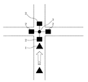
本発明の実施の形態について図面を参照して説明する。図1は、交差点の状況を示す図である。車両1は十字路交差点に向かって進行しており、交差点には、交差点でのそれぞれ異なる方位を撮影する複数の撮影装置(カメラ)2と、各撮影装置2が撮影した映像を送信するための情報送信装置3が設置されている。また、車両1には、情報送信装置3から送信された映像を受信するための情報受信装置が搭載されている。
Embodiments of the present invention will be described with reference to the drawings. FIG. 1 is a diagram illustrating the situation of an intersection. The
図2は、交差点に設置される本発明の情報送信装置の構成図である。情報送信装置3は、映像取得部11と、映像変換部12と、映像送信部13と、制御部15と、メモリ16とにより構成される。
映像取得部11は、交差点に設置された、交差点でのそれぞれ異なる方位を撮影する複数の撮影装置2に接続されており、撮影装置2が撮影した映像を取得する。
メモリ16には、情報送信装置の緯度/経度、情報送信装置の識別ID、各セグメントの映像の有無、進行方向毎の各セグメントの優先度表、撮影装置2と方位との対応付け、方位とセグメントとの対応付けの情報が記憶されており、映像変換部12は、メモリ16に記憶されている情報と制御部15からの制御によって、取得した映像を地上デジタル放送のフォーマットに変換する。映像変換部12は、1つの周波数帯域を用いて複数の番組を同時に放送可能な技術(ISDB−T(Integrated Service Digital Broadcasting-Terrestrial)、MediaFLO(Forward Link Only)などの技術)を用いることができ、映像取得部11が取得した複数の映像を、映像が取得された撮影装置2に対応する方位を基に各セグメントに割り当て、また、特定のセグメントに対して、情報送信装置の識別を表す情報(識別ID情報)と、どのセグメントにどの方位の映像が割り当てられているのかを示す値と、進行方向毎に各セグメントの優先度を表す値を付加する機能を有する。
映像送信部13は、変換後の映像を、指定のチャンネル周波数でアンテナ14を用いて送信する。情報送信装置3が映像を配信するチャンネルは、各都道府県の空きチャンネルまたは全国共通チャンネルが望ましい。なお、本発明は、映像変換部12と映像送信部13とで送信部を構成するものとする。
FIG. 2 is a configuration diagram of the information transmission apparatus of the present invention installed at an intersection. The
The video acquisition unit 11 is connected to a plurality of
In the
The
図3は、車両に搭載される本発明の情報受信装置の構成図である。本発明の情報受信装置は、例えば、車載のカーナビゲーション装置に適用可能である。図3に示す情報受信装置は、アンテナ21と、チューナ部22と、復調部23と、音声デコーダ部24と、映像デコーダ部25と、データ放送デコーダ部26と、スピーカ27と、映像制御部28と、映像表示部29と、操作入力部30と、制御部33と、情報受信装置を搭載する車両の位置を検出する車両位置検出部31と、情報受信装置を搭載する車両の進行方向を検出する進行方向検出部32と、メモリ34を備える。なお、必要に応じて、スピーカ27や映像表示部29は、本装置とは別に構成されるものでも良い。
FIG. 3 is a configuration diagram of the information receiving apparatus of the present invention mounted on a vehicle. The information receiving apparatus of the present invention is applicable to, for example, an in-vehicle car navigation apparatus. 3 includes an
チューナ部22は、情報送信装置3から送信された地上デジタル放送の信号をアンテナ21で受信して、制御部33からの周波数(チャンネル)指定命令に基づいてチューニングする。復調部23は、チューナ部22で周波数変換されたチャンネル信号をMPEG(Moving Picture Experts Group)のTS(Transport Stream)信号に復調し、TS信号内のパケットIDに基づいて音声パケット、映像パケット、データ放送パケットを検出し、それぞれのパケットを音声デコーダ部24、映像デコーダ部25、データ放送デコーダ部26に出力する。
The
音声デコーダ部24は、音声データをデコードし、スピーカ27に出力する。映像デコーダ部25は、映像データをデコードし、映像制御部28に出力する。データ放送デコーダ部26は、受信したBML(Broadcast Markup Language)を元に画面イメージを作成し、映像制御部28に出力する。また、データ放送デコーダ部26は、受信したBMLから番組表を取り出し、メモリ34に記憶する。
映像制御部28は、映像デコーダ部25およびデータ放送デコーダ部26から出力されたデータを制御部33からの命令に基づいて映像表示部29に出力する。映像表示部29は、映像デコーダ部25およびデータ放送デコーダ部26から出力されたデータや、メモリ34に記憶している地図などを表示する。
The audio decoder unit 24 decodes the audio data and outputs it to the
The
車両位置検出部31は、GPSやジャイロセンサーなどを用いて自車両の現在の位置を検出し、検出した位置の位置情報を制御部33に出力する。
進行方向検出部32は、加速度センサーと傾きを測定するジャイロセンサーを用いて自車両の現在の進行方向を検出し、検出した進行方向に関する情報を制御部33に出力する。なお、本実施例では、加速度センサーと傾きを測定するジャイロセンサーを用いて自車両の現在の進行方向を検出しているが、運転者によるウィンカ操作により進行方向を検出しても良い。また、運転者が、操作入力部30から進行方向を入力して、進行方向に関する情報を制御部33に出力するようにしても良い。
また、車両位置検出部31や進行方向検出部32も別に構成された部から情報だけを取得して検出するようにしても良い。
メモリ34は、地図情報51と、情報送信装置を識別するための情報送信装置情報52を記憶する。さらに、メモリ34は、BML、ラストチャンネル、番組表を記憶する。
The vehicle
The traveling
Further, the vehicle
The
また、制御部33は、車両位置判定部41と、情報送信装置判定部42と、情報取得部43と、映像分析部44と、優先度判定部45と、映像選択部46を備える。
情報取得部43と映像分析部44は、放送受信部が受信した放送信号の各セグメントから、映像信号と映像信号に対応する方位情報とを抽出する抽出部を構成する。
また、優先度判定部45と映像選択部46は、制御部の一部を構成し、抽出部が抽出した方位情報と地図上の方位に基づいて、映像表示部29が表示している地図上の方位に対応して、抽出部が抽出した映像信号を表示するように制御し、さらに、進行方向検出部32が検出した車両(情報受信装置)の進行方向に基づいて、優先的に表示する方位の順位(優先度)を決定し、決定した順位(優先度)に基づいて該方位に対応する映像信号を表示するように制御する。
The
The
Moreover, the
車両位置判定部41は、メモリ34内に記憶されている地図情報51と、車両位置検出部31から出力された位置情報と、進行方向検出部32から出力された進行方向に関する情報を用いて車両の現在位置および向きを判定する。また、車両位置判定部41は、判定された現在位置や向きと、メモリ34内に記憶されている情報送信装置情報52に含まれている情報送信装置の位置情報とを比較することによって、情報送信装置が設置されている地点に接近したことを検出した場合、上述した放送受信部を稼動させる機能を備える。
情報送信装置判定部42は、複数の情報送信装置を識別する。
情報取得部43は、情報送信装置が送信した情報送信装置の識別情報(情報送信装置の緯度/経度と、情報送信装置の識別ID)と、各セグメントの映像に関する情報(どのセグメントにどの方位の映像が割り当てられているのかを示す値と、進行方向毎に各セグメントの表示優先度を表す値)とを取得する。
映像分析部44は、放送受信部が受信した放送信号の各セグメントから、映像信号を抽出する。また、受信した映像を分析し、映像内に移動する物体(車両、人物など)が存在するかどうかを判定する。
優先度判定部45は、映像表示部29に表示する映像の優先度を判定する。
映像選択部46は、車両位置検出部31から出力された位置情報と、進行方向検出部32から出力された進行方向に関する情報と、映像分析部44が分析した映像内における移動物体の存在の有無に関する情報と、情報取得部43が取得した情報送信装置の識別情報(情報送信装置の緯度/経度と、情報送信装置の識別ID)と、各セグメントの映像に関する情報(どのセグメントにどの方位の映像が割り当てられているのかを示す値と、進行方向毎に各セグメントの表示優先度を表す値)とに基づいて、映像表示部29に表示する最適な映像を選択する。
The vehicle
The information transmission
The
The video analysis unit 44 extracts a video signal from each segment of the broadcast signal received by the broadcast reception unit. In addition, the received video is analyzed to determine whether there are moving objects (vehicles, people, etc.) in the video.
The
The
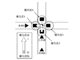
図4は、自車両が十字路交差点に接近しているときの自車両周辺の交通状況を示す図である。図4では自車両は十字路交差点に向かって進行しており、十字路交差点において右折する予定となっている。また、右側から他車両が接近してきている。交差点には交差点の交通状況を映像で取得するための撮影装置2と映像を送信するための情報送信装置3が設置されている。
FIG. 4 is a diagram illustrating a traffic situation around the own vehicle when the own vehicle is approaching the crossroad intersection. In FIG. 4, the host vehicle is traveling toward the crossroad intersection and is scheduled to turn right at the crossroad intersection. In addition, another vehicle is approaching from the right side. At the intersection, a photographing
図5は、図4の状態において、自車両に設置された情報受信装置の映像表示部に表示される映像を表す図である。情報受信装置の表示部には、情報受信装置のメモリ34に記憶されている地図情報51が表示され、地図情報上にはそれぞれの方向における映像が表示されている。また、進行方向である右側道路における映像が強調されて表示されている。
FIG. 5 is a diagram illustrating an image displayed on the image display unit of the information receiving apparatus installed in the own vehicle in the state of FIG. 4. The
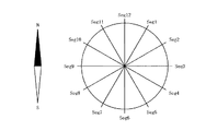
図6は、方位とセグメントとの関係を示す図であり、図7は、情報送信装置から送信される信号のセグメント構成を示す図である。図6および図7は、情報送信装置が撮影装置2から取得した映像情報を、映像が取得された方位に基づいて地上デジタル放送の信号の各セグメントに割り当てる方法を示している。各セグメントは方位を表しており、取得した映像情報は、方位が最も近似する方向を表すセグメントに配置される。また、セグメント0は、ガイドセグメントとし、情報送信装置の緯度/経度、情報送信装置の識別ID、各セグメントに割り当てられた映像の有無、進行方向毎の各セグメントの優先度表などの付加情報を送信するために用いられる。
FIG. 6 is a diagram showing the relationship between the direction and the segment, and FIG. 7 is a diagram showing the segment configuration of the signal transmitted from the information transmitting apparatus. 6 and 7 show a method of assigning video information acquired by the information transmission apparatus from the
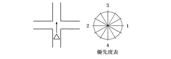
図8は、情報送信装置のメモリ16記憶されている優先度表に基づいて、十字路交差点において直進するときの各セグメントの映像表示に関する優先度(優先的に表示する方位の順位)を、方位と共に表した図である。優先度表によれば、十字路交差点で直進する場合、優先度は、右方向が最も高く、左方向、前方向、後方向の順に低くなる。図9は、十字路交差点で左折するときの各セグメントの映像表示に関する優先度を、方位と共に表した図である。優先度表によれば、十字路交差点で左折する場合、優先度は、左方向が最も高く、後方向、右方向、前方向の順に低くなる。図10は、十字路交差点で右折するときの各セグメントの映像表示に関する優先度を、方位と共に表した図である。優先度表によれば、十字路交差点で右折する場合、優先度は、右方向が最も高く、前方向、左方向、後方向の順に低くなる。
FIG. 8 shows the priorities related to the video display of each segment when moving straight at the intersection (based on the priority order) and the direction based on the priority table stored in the
優先度表は、情報受信装置が受信した映像の数と情報受信装置で再生可能な映像数を比較し、再生する映像を優先度の高い順に決定する場合に用いる。また、この優先度表は、情報受信装置のメモリ内に保持しても良いし、情報送信装置によって各セグメントにおける付加情報として送信しても良い。 The priority table is used when the number of videos received by the information receiving apparatus is compared with the number of videos that can be played back by the information receiving apparatus, and the videos to be played back are determined in descending order of priority. Further, this priority table may be held in the memory of the information receiving apparatus, or may be transmitted as additional information in each segment by the information transmitting apparatus.
図11は、自車両が十字路交差点で左折するときの自車両周辺の交通状況を示す図であり、図12は、図11の状態において、情報受信装置で再生可能な映像数が2で、情報送信装置から送信されている映像数が4の場合において、進行方向毎の各セグメントの優先度表を適用した場合に、情報受信装置の映像表示部に表示される映像を表した図である。この場合、自車両は左折をしようとしており、優先度表によれば、左折時に最も優先度の高い映像は、左折方向の映像であるので、左折方向の映像が強調して表示されている。次に優先度の高い映像は、後方を確認するために用いる巻き込み防止用の映像である。この巻き込み防止用の映像は、情報受信装置を搭載した車両の進行方向に対して反対方向の映像(車両後方の映像)であり、情報受信装置によって左右を反転した映像となっている。これは車両後方に装着されているカメラが撮影した映像のように見せたほうが車両運転者にとって好ましいからである。この場合、情報受信装置側では優先度の高い順に2つの映像を表示部に再生することになる。 FIG. 11 is a diagram showing the traffic situation around the host vehicle when the host vehicle makes a left turn at a crossroad intersection. FIG. 12 shows the number of images that can be reproduced by the information receiving device in the state of FIG. When the number of videos transmitted from the transmission device is 4, when the priority table of each segment for each traveling direction is applied, the image is displayed on the video display unit of the information reception device. In this case, the host vehicle is about to make a left turn, and according to the priority table, the image with the highest priority at the time of the left turn is the image in the left turn direction, so the image in the left turn direction is highlighted. The video with the next highest priority is a video for preventing entrainment used for confirming the rear. The image for preventing the entrainment is an image in the direction opposite to the traveling direction of the vehicle on which the information receiving device is mounted (image behind the vehicle), and is an image that is reversed left and right by the information receiving device. This is because it is preferable for the vehicle driver to look like an image taken by a camera mounted on the rear of the vehicle. In this case, on the information receiving apparatus side, the two videos are played back on the display unit in descending order of priority.
図13は、情報送信装置が隣接して設置されている場合を表す図である。情報送信装置は同一チャンネルで映像を送信しているため、お互いに影響を及ぼしあってしまう。したがって、設置時には、隣接する情報送信装置が送信する放送信号同士が干渉しないように送信出力を調整する必要がある。また、情報受信装置側では、情報送信装置の位置によって映像を受信する方向を変更可能なアンテナ技術が利用されることが望ましい。
また、図13に示すように、情報受信装置側で情報送信装置の設置場所を把握している場合、情報送信装置を識別IDで識別して、受信エリアの接近をトリガにして放送受信部の電源をONにし、受信エリア外となった場合には、放送受信部の電源をOFFとすることで、消費電力の削減を行うことも考えられる。
FIG. 13 is a diagram illustrating a case where information transmission apparatuses are installed adjacent to each other. Since the information transmitting apparatuses transmit images on the same channel, they affect each other. Therefore, at the time of installation, it is necessary to adjust the transmission output so that broadcast signals transmitted by adjacent information transmission apparatuses do not interfere with each other. Moreover, it is desirable that the information receiving apparatus side uses an antenna technique that can change the direction in which the video is received depending on the position of the information transmitting apparatus.
Further, as shown in FIG. 13, when the information receiving apparatus side knows the installation location of the information transmitting apparatus, the information transmitting apparatus is identified by the identification ID, and the approach of the receiving area is used as a trigger. If the power is turned on and the broadcast receiving unit is out of the reception area, the power consumption of the broadcast receiving unit may be turned off to reduce power consumption.
図14は、情報受信装置が放送信号を受信した場合における優先度表を用いた映像割り当て手順を表すフローチャートである。まず、情報受信装置は、情報送信装置から映像を含む放送信号を受信すると(ステップ101)、セグメント0の付加情報の内容を解析し、セグメントに割り当てられている映像数を確認する(ステップ102)。次に、情報受信装置が再生可能な映像数(=デコーダ数)と映像数を比較し(ステップ103)、デコーダ数が、セグメントに割り当てられている映像数より上回っている場合(YESの場合)は、全映像をデコーダに割り当て(ステップ104)、映像再生を開始する(ステップ105)。デコーダ数が映像数を満たしていない場合(NOの場合)は、優先度表を利用し、優先度の高い順に映像をデコーダに割り当て(ステップ106)、映像の再生を開始する(ステップ105)。
FIG. 14 is a flowchart showing a video assignment procedure using a priority table when the information receiving apparatus receives a broadcast signal. First, when the information receiving apparatus receives a broadcast signal including video from the information transmitting apparatus (step 101), the information receiving apparatus analyzes the content of the additional information of the
上述したように、本発明の情報送信装置は、輻輳などによる遅延が発生することがある通信技術ではなく、放送技術を使用するので、全ての車両に対して同時に遅延なく映像を送信することが可能となる。
また、本発明の情報受信装置は、表示部に表示する映像をただ1つに選択するのではなく、受信する映像に優先度を設けることで優先度順に表示する。情報受信装置の処理能力によって1つしか映像を出せない性能であれば最も優先度の高い映像を1つ表示し、複数の映像を表示可能であれば、優先度の高い順に表示可能な数だけ映像を表示する。したがって、映像をただ1つに選択する必要がなくなる。
また、本発明の情報受信装置は、映像を切り換えながら表示するのではなく、必要な複数の映像を同時に表示し、車両の状況に応じて最も注意すべき映像を強調するような処理を加える。したがって、車両運転者は必要に応じて様々な映像を自由に確認することができ、また注意すべき映像は強調されているため、特に注意して確認することも可能となる。
As described above, the information transmission apparatus according to the present invention uses a broadcasting technique rather than a communication technique that may cause a delay due to congestion or the like, and therefore can transmit video to all vehicles simultaneously without delay. It becomes possible.
In addition, the information receiving apparatus of the present invention does not select only one video to be displayed on the display unit but displays the received video in order of priority by providing priority. If the performance is such that only one video can be displayed depending on the processing capability of the information receiving device, one video with the highest priority is displayed, and if multiple videos can be displayed, only the number that can be displayed in the order of priority. Display video. Therefore, it is not necessary to select only one video.
In addition, the information receiving apparatus of the present invention does not display while switching the video, but displays a plurality of necessary videos at the same time, and adds a process for emphasizing the video that should be most watched according to the situation of the vehicle. Therefore, the vehicle driver can freely check various images as necessary, and since the images to be noted are emphasized, it is also possible to check with particular care.
1 車両
2 撮影装置
3 情報送信装置
11 映像取得部
12 映像変換部
13 映像送信部
14,21 アンテナ
15,33 制御部
16,34 メモリ
22 チューナ部
23 復調部
24 音声デコーダ部
25 映像デコーダ部
26 データ放送デコーダ部
27 スピーカ
28 映像制御部
29 映像表示部
30 操作入力部
31 車両位置検出部
32 進行方向検出部
41 車両位置判定部
42 情報送信装置判定部
43 情報取得部
44 映像分析部
45 優先度判定部
46 映像選択部
51 地図情報
52 情報送信装置情報
DESCRIPTION OF
Claims (6)
それぞれ異なる方位を撮影するために設置された複数の撮影装置から、それぞれの撮影装置が撮影した映像を取得する取得部と、
該取得部が取得した映像を、各撮影装置が撮影する方位に対応するセグメントのそれぞれに割り当てて、送信する送信部と、
を備える送信装置。 In a transmission device that transmits a broadcast signal whose transmission band is divided into a plurality of segments,
An acquisition unit that acquires images captured by each of the imaging devices from a plurality of imaging devices installed to capture different orientations;
A transmission unit that allocates and transmits the video acquired by the acquisition unit to each of the segments corresponding to the azimuths captured by each imaging device;
A transmission apparatus comprising:
該受信部が受信した放送信号の各セグメントから、映像信号と該映像信号に対応する方位情報とを抽出する抽出部と、
地図を表示する表示部と、
前記抽出部が抽出した方位情報と地図上の方位に基づいて、前記表示部が表示している当該地図上の方位に対して、前記抽出部が抽出した映像信号を表示するように制御する制御部と、
を備える受信装置。 A receiver for receiving a broadcast signal whose transmission band is divided into a plurality of segments;
An extraction unit that extracts a video signal and direction information corresponding to the video signal from each segment of the broadcast signal received by the reception unit;
A display for displaying a map;
Control for controlling to display the video signal extracted by the extraction unit with respect to the direction on the map displayed by the display unit based on the direction information extracted by the extraction unit and the direction on the map And
A receiving device.
前記制御部は、前記検出部が検出した受信装置の進行方向に基づいて、優先的に表示する方位の順位を決定し、決定した順位に基づいて該方位に対応する映像信号を表示することを特徴とする請求項3に記載の受信装置。 A detection unit for detecting the traveling direction of the moving receiving device;
The control unit determines the order of orientation to be preferentially displayed based on the traveling direction of the receiving device detected by the detection unit, and displays a video signal corresponding to the orientation based on the determined order. The receiving device according to claim 3, wherein
Priority Applications (1)
| Application Number | Priority Date | Filing Date | Title |
|---|---|---|---|
| JP2008168695A JP5280118B2 (en) | 2008-06-27 | 2008-06-27 | Transmitter and receiver |
Applications Claiming Priority (1)
| Application Number | Priority Date | Filing Date | Title |
|---|---|---|---|
| JP2008168695A JP5280118B2 (en) | 2008-06-27 | 2008-06-27 | Transmitter and receiver |
Publications (2)
| Publication Number | Publication Date |
|---|---|
| JP2010009359A true JP2010009359A (en) | 2010-01-14 |
| JP5280118B2 JP5280118B2 (en) | 2013-09-04 |
Family
ID=41589767
Family Applications (1)
| Application Number | Title | Priority Date | Filing Date |
|---|---|---|---|
| JP2008168695A Active JP5280118B2 (en) | 2008-06-27 | 2008-06-27 | Transmitter and receiver |
Country Status (1)
| Country | Link |
|---|---|
| JP (1) | JP5280118B2 (en) |
Cited By (1)
| Publication number | Priority date | Publication date | Assignee | Title |
|---|---|---|---|---|
| WO2021095481A1 (en) * | 2019-11-13 | 2021-05-20 | パナソニック株式会社 | Driving assistance method, roadside device, and in-vehicle device |
Citations (14)
| Publication number | Priority date | Publication date | Assignee | Title |
|---|---|---|---|---|
| JPH08129700A (en) * | 1994-11-01 | 1996-05-21 | Nippondenso Co Ltd | Dead-angle image transmission and reception device |
| JPH09180087A (en) * | 1995-12-25 | 1997-07-11 | Sumitomo Electric Ind Ltd | Traffic information provision system |
| JPH11161888A (en) * | 1997-11-28 | 1999-06-18 | Hitachi Denshi Ltd | Itv display method/device for monitoring important traffic point |
| JP2001184595A (en) * | 1999-12-27 | 2001-07-06 | Matsushita Electric Ind Co Ltd | Transmitting system, transmitter, receiver, display device and vehicle |
| JP2002117496A (en) * | 2000-10-12 | 2002-04-19 | Matsushita Electric Ind Co Ltd | On-vehicle rear confirmation support device and on- vehicle navigation device |
| JP2003177026A (en) * | 2001-08-14 | 2003-06-27 | Matsushita Electric Ind Co Ltd | Navigation apparatus and selecting method for information |
| JP2006023985A (en) * | 2004-07-08 | 2006-01-26 | Nissan Motor Co Ltd | Traffic information providing system, traffic information providing method, information providing device and on-vehicle information terminal |
| JP2006078357A (en) * | 2004-09-10 | 2006-03-23 | Alpine Electronics Inc | Navigation system and navigation method |
| JP2006267754A (en) * | 2005-03-25 | 2006-10-05 | Keikaku Gijutsu Kenkyusho:Kk | Voice guidance apparatus using weak electric wave |
| JP2007089083A (en) * | 2005-09-26 | 2007-04-05 | Pioneer Electronic Corp | Receiver |
| JP2007108837A (en) * | 2005-10-11 | 2007-04-26 | Matsushita Electric Ind Co Ltd | On-board communication device and inter-vehicle communication system |
| JP2007306363A (en) * | 2006-05-12 | 2007-11-22 | Pioneer Electronic Corp | Digital broadcast receiver |
| JP2008070955A (en) * | 2006-09-12 | 2008-03-27 | Sumitomo Electric Ind Ltd | Display system for displaying traveling object, on-vehicle apparatus, image transmitter and display method |
| JP2008068837A (en) * | 2006-09-15 | 2008-03-27 | Toyota Motor Corp | Electric parking brake system |
-
2008
- 2008-06-27 JP JP2008168695A patent/JP5280118B2/en active Active
Patent Citations (14)
| Publication number | Priority date | Publication date | Assignee | Title |
|---|---|---|---|---|
| JPH08129700A (en) * | 1994-11-01 | 1996-05-21 | Nippondenso Co Ltd | Dead-angle image transmission and reception device |
| JPH09180087A (en) * | 1995-12-25 | 1997-07-11 | Sumitomo Electric Ind Ltd | Traffic information provision system |
| JPH11161888A (en) * | 1997-11-28 | 1999-06-18 | Hitachi Denshi Ltd | Itv display method/device for monitoring important traffic point |
| JP2001184595A (en) * | 1999-12-27 | 2001-07-06 | Matsushita Electric Ind Co Ltd | Transmitting system, transmitter, receiver, display device and vehicle |
| JP2002117496A (en) * | 2000-10-12 | 2002-04-19 | Matsushita Electric Ind Co Ltd | On-vehicle rear confirmation support device and on- vehicle navigation device |
| JP2003177026A (en) * | 2001-08-14 | 2003-06-27 | Matsushita Electric Ind Co Ltd | Navigation apparatus and selecting method for information |
| JP2006023985A (en) * | 2004-07-08 | 2006-01-26 | Nissan Motor Co Ltd | Traffic information providing system, traffic information providing method, information providing device and on-vehicle information terminal |
| JP2006078357A (en) * | 2004-09-10 | 2006-03-23 | Alpine Electronics Inc | Navigation system and navigation method |
| JP2006267754A (en) * | 2005-03-25 | 2006-10-05 | Keikaku Gijutsu Kenkyusho:Kk | Voice guidance apparatus using weak electric wave |
| JP2007089083A (en) * | 2005-09-26 | 2007-04-05 | Pioneer Electronic Corp | Receiver |
| JP2007108837A (en) * | 2005-10-11 | 2007-04-26 | Matsushita Electric Ind Co Ltd | On-board communication device and inter-vehicle communication system |
| JP2007306363A (en) * | 2006-05-12 | 2007-11-22 | Pioneer Electronic Corp | Digital broadcast receiver |
| JP2008070955A (en) * | 2006-09-12 | 2008-03-27 | Sumitomo Electric Ind Ltd | Display system for displaying traveling object, on-vehicle apparatus, image transmitter and display method |
| JP2008068837A (en) * | 2006-09-15 | 2008-03-27 | Toyota Motor Corp | Electric parking brake system |
Cited By (2)
| Publication number | Priority date | Publication date | Assignee | Title |
|---|---|---|---|---|
| WO2021095481A1 (en) * | 2019-11-13 | 2021-05-20 | パナソニック株式会社 | Driving assistance method, roadside device, and in-vehicle device |
| JP7349888B2 (en) | 2019-11-13 | 2023-09-25 | パナソニックホールディングス株式会社 | Driving support method and in-vehicle device |
Also Published As
| Publication number | Publication date |
|---|---|
| JP5280118B2 (en) | 2013-09-04 |
Similar Documents
| Publication | Publication Date | Title |
|---|---|---|
| KR101431264B1 (en) | Terminal for receiving traffic information, method of providing singal lamp information, and method of guiding a signal | |
| EP2442291A1 (en) | Traffic event monitoring | |
| KR20000068332A (en) | Satellite broadcasting system | |
| US20170025011A1 (en) | Radio device | |
| KR102572667B1 (en) | Communication device | |
| US20050273233A1 (en) | In-vehicle electronic apparatus and method for displaying digital broadcast in the same | |
| JP2002053043A (en) | Platform monitoring device ! stairway ascending cart | |
| JP2006270378A (en) | Onboard television display device | |
| JP2001077712A (en) | Device and method for receiving digital broadcasting | |
| JP5280118B2 (en) | Transmitter and receiver | |
| JP2001053635A (en) | Receiver and receiving method | |
| JP2009059039A (en) | On-vehicle device for preventing stop within intersection, system for preventing stop within intersection, program for this device, on-vehicle device for preventing stop within railroad crossing, system for preventing stop within railroad crossing, and program for this device | |
| JP4923579B2 (en) | Behavior information acquisition device, display terminal, and behavior information notification system | |
| JP4582945B2 (en) | In-vehicle information processing system and information processing method | |
| JP4813978B2 (en) | In-vehicle information provider | |
| CN103313112B (en) | Semiconductor equipment and its signal processing method | |
| JP4089466B2 (en) | Car broadcast receiver | |
| JP2010014487A (en) | Navigation device | |
| JP2007145283A (en) | On-vehicle device | |
| JP3501052B2 (en) | Image processing device for vehicles | |
| JP4752713B2 (en) | Television receiver | |
| JP6678618B2 (en) | Digital broadcast receiving apparatus and digital broadcast receiving program | |
| JP2007201590A (en) | Vehicle-mounted video apparatus | |
| KR101325833B1 (en) | Broadcasting receiver providing traffic information service and operating method thereof | |
| JP2006248349A (en) | On-vehicle digital broadcasting receiving device |
Legal Events
| Date | Code | Title | Description |
|---|---|---|---|
| A621 | Written request for application examination |
Free format text: JAPANESE INTERMEDIATE CODE: A621 Effective date: 20110530 |
|
| A977 | Report on retrieval |
Free format text: JAPANESE INTERMEDIATE CODE: A971007 Effective date: 20121121 |
|
| A131 | Notification of reasons for refusal |
Free format text: JAPANESE INTERMEDIATE CODE: A131 Effective date: 20121204 |
|
| A521 | Written amendment |
Free format text: JAPANESE INTERMEDIATE CODE: A523 Effective date: 20130204 |
|
| TRDD | Decision of grant or rejection written | ||
| A01 | Written decision to grant a patent or to grant a registration (utility model) |
Free format text: JAPANESE INTERMEDIATE CODE: A01 Effective date: 20130423 |
|
| A61 | First payment of annual fees (during grant procedure) |
Free format text: JAPANESE INTERMEDIATE CODE: A61 Effective date: 20130522 |
|
| R150 | Certificate of patent or registration of utility model |
Free format text: JAPANESE INTERMEDIATE CODE: R150 Ref document number: 5280118 Country of ref document: JP Free format text: JAPANESE INTERMEDIATE CODE: R150 |