JP2010009024A - Image forming apparatus and double-sided image forming apparatus - Google Patents
Image forming apparatus and double-sided image forming apparatus Download PDFInfo
- Publication number
- JP2010009024A JP2010009024A JP2009117594A JP2009117594A JP2010009024A JP 2010009024 A JP2010009024 A JP 2010009024A JP 2009117594 A JP2009117594 A JP 2009117594A JP 2009117594 A JP2009117594 A JP 2009117594A JP 2010009024 A JP2010009024 A JP 2010009024A
- Authority
- JP
- Japan
- Prior art keywords
- transfer material
- image
- transfer
- timing
- image forming
- Prior art date
- Legal status (The legal status is an assumption and is not a legal conclusion. Google has not performed a legal analysis and makes no representation as to the accuracy of the status listed.)
- Granted
Links
Images


Classifications
-
- G—PHYSICS
- G03—PHOTOGRAPHY; CINEMATOGRAPHY; ANALOGOUS TECHNIQUES USING WAVES OTHER THAN OPTICAL WAVES; ELECTROGRAPHY; HOLOGRAPHY
- G03G—ELECTROGRAPHY; ELECTROPHOTOGRAPHY; MAGNETOGRAPHY
- G03G15/00—Apparatus for electrographic processes using a charge pattern
- G03G15/22—Apparatus for electrographic processes using a charge pattern involving the combination of more than one step according to groups G03G13/02 - G03G13/20
- G03G15/23—Apparatus for electrographic processes using a charge pattern involving the combination of more than one step according to groups G03G13/02 - G03G13/20 specially adapted for copying both sides of an original or for copying on both sides of a recording or image-receiving material
- G03G15/231—Arrangements for copying on both sides of a recording or image-receiving material
- G03G15/232—Arrangements for copying on both sides of a recording or image-receiving material using a single reusable electrographic recording member
- G03G15/234—Arrangements for copying on both sides of a recording or image-receiving material using a single reusable electrographic recording member by inverting and refeeding the image receiving material with an image on one face to the recording member to transfer a second image on its second face, e.g. by using a duplex tray; Details of duplex trays or inverters
-
- G—PHYSICS
- G03—PHOTOGRAPHY; CINEMATOGRAPHY; ANALOGOUS TECHNIQUES USING WAVES OTHER THAN OPTICAL WAVES; ELECTROGRAPHY; HOLOGRAPHY
- G03G—ELECTROGRAPHY; ELECTROPHOTOGRAPHY; MAGNETOGRAPHY
- G03G15/00—Apparatus for electrographic processes using a charge pattern
- G03G15/14—Apparatus for electrographic processes using a charge pattern for transferring a pattern to a second base
- G03G15/16—Apparatus for electrographic processes using a charge pattern for transferring a pattern to a second base of a toner pattern, e.g. a powder pattern, e.g. magnetic transfer
- G03G15/1605—Apparatus for electrographic processes using a charge pattern for transferring a pattern to a second base of a toner pattern, e.g. a powder pattern, e.g. magnetic transfer using at least one intermediate support
-
- G—PHYSICS
- G03—PHOTOGRAPHY; CINEMATOGRAPHY; ANALOGOUS TECHNIQUES USING WAVES OTHER THAN OPTICAL WAVES; ELECTROGRAPHY; HOLOGRAPHY
- G03G—ELECTROGRAPHY; ELECTROPHOTOGRAPHY; MAGNETOGRAPHY
- G03G2215/00—Apparatus for electrophotographic processes
- G03G2215/01—Apparatus for electrophotographic processes for producing multicoloured copies
- G03G2215/0103—Plural electrographic recording members
- G03G2215/0119—Linear arrangement adjacent plural transfer points
- G03G2215/0122—Linear arrangement adjacent plural transfer points primary transfer to an intermediate transfer belt
- G03G2215/0125—Linear arrangement adjacent plural transfer points primary transfer to an intermediate transfer belt the linear arrangement being horizontal or slanted
- G03G2215/0132—Linear arrangement adjacent plural transfer points primary transfer to an intermediate transfer belt the linear arrangement being horizontal or slanted vertical medium transport path at the secondary transfer
Abstract
Description
本発明は、画像形成装置に関するものであり、転写材の両面に画像を形成する画像形成装置に関するものである。 The present invention relates to an image forming apparatus, and more particularly to an image forming apparatus that forms images on both sides of a transfer material.
従来の画像形成装置の構成について以下に説明する。 The configuration of a conventional image forming apparatus will be described below.
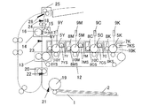
<カラー画像形成装置の構成>
図8はカラー画像形成装置としてのレーザプリンタの一例を示す概略全体構成図である。画像形成装置は、図8に示すように画像形成部において、図示しないコントローラ部から送信された画像信号に基づいて形成される画像光により静電潜像を形成し、この静電潜像を現像して可視画像を重畳転写してカラー可視画像を形成する。そして、このカラー可視画像を転写材へ転写し、その転写材上のカラー可視画像を定着させるものである。画像形成部は、まず、現像色分並置したステーション毎の像担持体としての感光ドラム5Y、5M、5C、5K(複数の像担持体)、一次帯電手段としての帯電器7Y、7M、7C、7Kにより構成される。また、画像形成部は、現像手段としての現像器8Y、8M、8C、8K、中間転写体としての中間転写ベルト12、二次転写位置13となる転写部、定着器14、給紙ローラ19及びレジストローラ20によって構成されている。
<Configuration of color image forming apparatus>
FIG. 8 is a schematic overall configuration diagram showing an example of a laser printer as a color image forming apparatus. As shown in FIG. 8, the image forming apparatus forms an electrostatic latent image with image light formed based on an image signal transmitted from a controller unit (not shown) in the image forming unit, and develops the electrostatic latent image. The visible image is superimposed and transferred to form a color visible image. The color visible image is transferred to a transfer material, and the color visible image on the transfer material is fixed. First, the image forming unit includes
感光ドラム5Y、5M、5C、5K、帯電器7Y、7M、7C、7K、現像器8Y、8M、8C、8Kは、画像形成装置本体に着脱可能なトナーカートリッジ10Y、10M、10C、10Kに搭載されている。
The
感光ドラム5Y、5M、5C、5Kは、アルミシリンダの外周に有機光導伝層を塗布して構成し、図示しない駆動モータの駆動力が伝達されて回転するものである。そして、駆動モータは感光ドラム5Y、5M、5C、5Kを画像形成動作に応じて反時計周り方向に回転させる。感光ドラム5Y、5M、5C、5Kへの露光光はスキャナ部9Y、9M、9C、9Kから送られ、感光ドラム5Y、5M、5C、5Kの表面(像担持体上)に選択的に露光することにより、静電潜像が形成されるように構成されている。
The
一次帯電手段は、ステーション毎にイエロー(Y)、マゼンタ(M)、シアン(C)、ブラック(K)の感光ドラムを帯電させるための4個の帯電器7Y、7M、7C、7Kを備える構成である。また、各帯電器7Y、7M、7C、7Kにはスリーブ7YS、7MS、7CS、7KSが備えられている。
The primary charging means includes four
現像手段は、静電潜像を可視化するために、ステーション毎にイエロー(Y)、マゼンタ(M)、シアン(C)、ブラック(K)の現像を行う4個の現像器8Y、8M、8C、8Kを備える構成である。そして、各現像器8Y、8M、8C、8Kには、スリーブ8YS、8MS、8CS、8CKが設けられている。
The developing means includes four developing
中間転写ベルト12は、感光ドラム5Y、5M、5C、5Kに接触しており、カラー画像形成時に感光ドラム5Y、5M、5C、5Kの回転に伴って時計回りに回転し、可視画像の転写(一次転写)を受ける。また、転写材を挟持搬送することにより転写材と中間転写ベルト12上のカラー可視画像(多色のトナー像)を同時に重畳転写(多重転写)する。
The
二次転写位置13となる転写部は、中間転写ベルト12に接触している。そして、中間転写ベルト12の回転に伴って反時計回りに回転し、レジストローラ20から搬送された転写材に対して中間転写ベルト12上(中間転写体上)のカラー可視画像を転写(二次転写)する。
The transfer portion serving as the
なお、1は給紙カセット、2は転写材、21は給紙センサであり、給紙カセット1から給紙された転写材が所定時間内に給紙センサ21まで達しているかを検知する。検知結果によって給紙した際の転写材2の搬送不良を検知できる。また、22はレジセンサであり、中間転写ベルト12上に形成された画像と給紙された転写材2との同期をとるために設けられている。転写材2の先端がレジセンサ22で検知されたタイミングで転写材2を一次停止させて、中間転写ベルト12上に形成された画像が転写材2の所定の位置に転写されるように転写材2を再度搬送するタイミングを制御する。23は定着前センサ、24は定着排紙センサである。また、定着器14は、加圧ローラ16及び定着ローラ15を有し、定着ローラ15内にはヒータ17が設けられている。18はサーミスタであり、定着ローラ15の表面温度を検知し、この検知結果に基づきヒータ17への通電が制御される。なお、25は転写材2を排紙するための排紙ローラである。また、26は転写材2の両面に画像を形成するために転写材2の搬送路を切り換えるための反転フラッパである。
<画像形成装置のシステム構成>
図9は、画像形成装置としてのレーザプリンタの概略システム構成を説明するためのブロック図である。コントローラ制御部201は、ホストコンピュータ200、エンジン制御部202と相互に通信が可能となっている(図9の220、222)。
<System configuration of image forming apparatus>
FIG. 9 is a block diagram for explaining a schematic system configuration of a laser printer as an image forming apparatus. The
コントローラ制御部201は、ホストコンピュータ200から画像情報と印字条件を受け取る。コントローラ制御部201は、受け取った印字条件を基に、転写材毎の印字情報を付加した印字動作の予約を行う印字予約コマンドをエンジン制御部202へ送信し、受け取った画像情報を解析してビットデータに変換する。ここで、転写材毎の印字情報とは、例えば、給紙口(給紙カセット)、転写材サイズ、印字モード等である。コントローラ制御部201は、画像情報の解析が終了した時点で、エンジン制御部202へ印字動作の開始を指示するための印字開始コマンドを送信する。エンジン制御部202は、印字開始コマンドを受信すると、イエローの画像形成部である第一ステーションに対するビデオ信号の出力の基準タイミングとなる/TOP信号(図9の221)を出力する。そして、給紙動作を開始し、給紙された転写材2をレジストローラ20で一時待機させる。その後、中間転写ベルト12上に形成されたトナー像が二次転写位置13に到達するのに合わせて、レジストローラ20から転写材2を再給紙する。なお、210はビデオインターフェイス部、211はCPU、212は画像処理GA、213は画像制御部、214は定着制御部、215は用紙搬送部、216は駆動制御部である。
The
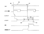
<両面プリント時のタイミングチャート>
図10は両面プリント(両面印刷)において最速のスループットを実現する場合のタイミングチャートである。タイミングチャートには/TOP信号(/TOP)、レジストローラ20の駆動(レジローラ駆動)、転写材2のピックアップ動作、レジセンサ22による検知信号、反転動作、定着排紙センサ24による検知信号が示されている。また、タイミングチャート上で破線で示される各時点に対応して、画像形成装置の状態を(a)〜(e)の順に示す。なお、スループットは、単位時間当たりの画像形成数(印刷枚数)のことであり、最速のスループットを実現するためには、1面目の/TOP信号と2面目の/TOP信号を出力する時間間隔(図10の300参照)を最短にする必要がある。
<Timing chart for duplex printing>
FIG. 10 is a timing chart for realizing the fastest throughput in double-sided printing (double-sided printing). The timing chart shows the / TOP signal (/ TOP), the driving of the registration roller 20 (registration roller driving), the pickup operation of the
エンジン制御部202は、コントローラ制御部201から印字開始コマンドを受信すると、プリントの準備を行ない、準備が整うと1面目の/TOP信号を出力(311)(a)し、転写材2の給紙動作を開始する(312)。エンジン制御部202は、ピックアップされた転写材2が、レジセンサ22が配置されるレジストローラ20に到達した時点(313)で、転写材2の搬送を一時停止する(314)。そして、中間転写ベルト12上に形成したトナー像t1に合わせて、転写材2の搬送を再開(315)(b)して、トナー像t1を転写材2に転写する。エンジン制御部202は、その後、定着器14によってトナー像t1を転写材2に熱定着する。
When the
その後、転写材2の後端が定着排紙センサ24を抜けて(316)(c)、反転可能な位置まで転写材2を搬送し、反転フラッパ26及び図示しない反転ソレノイドをオン(ON)することで反転動作を開始する(317)(d)。次に、反転フラッパ26により搬送路を両面パスに切り替えて転写材2を両面パスに搬送する。エンジン制御部202は、反転した転写材2がレジストローラ20に到達した時点(323)で、転写材2の搬送を一時停止する(324)。そして、中間転写ベルト12上に形成した2面目のトナー像t2に合わせて、転写材2の搬送を再開(325)(e)して、トナー像t2を転写材2に転写する。
Thereafter, the rear end of the
最速スループットを実現するための2面目の/TOP信号の出力タイミング(321)は、エンジン制御部202がコントローラ制御部201から指定された転写材サイズを基に、次の時間を基準に決定される。すなわち、1面目のトナー像t1が二次転写位置13で転写材2に転写され、その転写材2が反転(317)し再度レジストローラ20に到達する(323)までの時間を基準に逆算して決定される。
The output timing (321) of the / TOP signal on the second side for realizing the fastest throughput is determined based on the next time based on the transfer material size designated by the
上述したように、2面目の/TOP信号の出力タイミングは、コントローラ制御部201から指定された転写材サイズを基にその転写材の2面目が反転してレジストローラ20に到達するタイミングから逆算して決定される。このため、実際に給紙部である給紙カセット1にセットされた転写材2の搬送方向のサイズがコントローラ制御部201から指定された転写材サイズよりも大きい場合には、転写材2が反転するタイミングは想定したタイミングよりも遅くなる。その結果、中間転写ベルト12上に形成された2面目のトナー像t2が二次転写位置13に到達するタイミングまでに転写材2がレジストローラ20に到達せずに、転写材2の滞留、紙詰まり(ジャム)が発生する。
As described above, the output timing of the / TOP signal on the second side is calculated backward from the timing at which the second side of the transfer material is reversed and reaches the
このため、例えば特許文献1や特許文献2では、次のようにしてジャムの発生を回避している。すなわち、転写材搬送路上のセンサを用いて、1面目に給紙された転写材の搬送方向のサイズ(長さ)を検出する。そして、検出された転写材の搬送方向のサイズと指定された転写材の搬送方向のサイズとが一致しない場合は、プリントに失敗したことを意味する紙サイズ不一致によるプリントエラーを出力する。そして、転写材を機外に排出して印刷動作を停止することで、ジャムになった場合に必要なユーザによる転写材の除去処理を不要にしている。
For this reason, for example, in
しかしながら、上記のような従来例の装置では、給紙された転写材の搬送方向のサイズが指定されたサイズよりも大きい場合に両面プリントを実施すると、紙サイズ不一致によるプリントエラーとなる。このため、エラーが確定した時には中間転写ベルト12上に2面目のトナー画像が残留するためトナーが無駄になる。さらに、正常終了した場合と比べて無駄になったトナーの回収作業に時間を要する。
However, in the conventional apparatus as described above, if double-sided printing is performed when the size of the fed transfer material in the transport direction is larger than the specified size, a print error occurs due to paper size mismatch. For this reason, when the error is confirmed, the toner image on the second surface remains on the
本発明は、このような状況のもとでなされたもので、転写材の搬送方向のサイズ不一致によるエラーをなくし、さらに、給紙された転写材の搬送方向のサイズに適したスループットでのプリント動作を行うことを目的とする。 The present invention has been made under such circumstances, eliminates an error due to size mismatch in the transfer material conveyance direction, and further prints with a throughput suitable for the size of the fed transfer material in the conveyance direction. The purpose is to perform the operation.
上記課題を解決するために、本発明は以下の構成を備える。 In order to solve the above problems, the present invention comprises the following arrangement.
(1)像担持体に画像を形成する画像形成部と、前記像担持体に形成された画像が転写される中間転写体と、転写材に前記中間転写体上に形成された画像を転写する転写部と、前記転写部により画像が転写される前に、搬送される転写材を検知する検知部と、1面目に画像が形成された転写材を反転させ、再度、前記転写部に搬送する搬送部と、指定された転写材の搬送方向のサイズに基づいて、前記画像形成部によって画像形成を開始するタイミングを制御する制御部と、を備え、前記制御部は、転写材の2面目に画像形成をする際の前記画像形成部によって画像形成を開始するタイミングを、指定された転写材の搬送方向のサイズと搬送された転写材の搬送方向のサイズに基づいて切り換えることを特徴とする画像形成装置。 (1) An image forming unit that forms an image on an image carrier, an intermediate transfer member to which an image formed on the image carrier is transferred, and an image formed on the intermediate transfer member are transferred to a transfer material. Before the image is transferred by the transfer unit, the transfer unit, the detection unit for detecting the transfer material to be conveyed, and the transfer material on which the image is formed on the first surface are reversed and conveyed to the transfer unit again. A transport unit, and a control unit that controls a timing at which image formation is started by the image forming unit based on a designated size in the transport direction of the transfer material, and the control unit is provided on the second surface of the transfer material. An image characterized in that the timing of starting image formation by the image forming unit when forming an image is switched based on the size of the designated transfer material in the transport direction and the size of the transported transfer material in the transport direction Forming equipment.
(2)転写材の両面に画像を形成する両面画像形成装置において、画像形成部により像担持体に形成された画像が転写される中間転写体と、前記中間転写体に形成された画像を転写材に転写する転写部と、前記転写部により画像が転写される前に、搬送される転写材を検知する検知部と、1面目に画像が形成された転写材を反転させ、再度、前記転写部に搬送する両面搬送部と、を備え、転写材の2面目に画像形成をする際の前記画像形成部による画像形成のタイミングを、指定された転写材の搬送方向のサイズと搬送された転写材のサイズに基づいて切り換えることを特徴とする両面画像形成装置。 (2) In a double-sided image forming apparatus that forms images on both sides of a transfer material, an intermediate transfer member to which an image formed on an image carrier is transferred by an image forming unit, and an image formed on the intermediate transfer member are transferred. A transfer unit that transfers to the material, a detection unit that detects the transfer material that is conveyed before the image is transferred by the transfer unit, and a transfer material on which an image is formed on the first surface is reversed, and the transfer is performed again. A double-sided conveyance unit that conveys the image onto the second side of the transfer material, the image formation timing by the image forming unit when forming an image on the second surface of the transfer material, and the size of the designated transfer material in the conveyance direction and the conveyed transfer A double-sided image forming apparatus, wherein switching is performed based on a material size.
本発明によれば、転写材の搬送方向のサイズ不一致によるエラーをなくし、さらに、給紙された転写材の搬送方向のサイズに適したスループットでのプリント動作を行うことが可能となる。 According to the present invention, it is possible to eliminate errors due to size mismatch in the transfer material conveyance direction, and to perform a print operation with a throughput suitable for the size of the fed transfer material in the conveyance direction.
以下に、本発明の実施例に係る画像形成装置について図面を用いて詳しく説明する。なお、以下に示す実施例は一例であって、この発明の技術的範囲をそれらのみに限定する趣旨のものではない。 Hereinafter, an image forming apparatus according to an embodiment of the present invention will be described in detail with reference to the drawings. In addition, the Example shown below is an example, Comprising: It is not the meaning which limits the technical scope of this invention only to them.
本実施例における画像形成装置は、上述した図8、図9で説明した構成と同様であるため説明を省略し、以下同じ符号を用いて説明する。 The image forming apparatus in the present embodiment is the same as the configuration described with reference to FIGS. 8 and 9 described above, and therefore description thereof will be omitted.
本実施例における画像形成装置は次のような構成である。すなわち画像形成を開始してからトナー像の先端が二次転写位置13に到達するまでの時間が、転写材2(以降、「用紙2」とする)の後端がレジセンサ22を抜けてから反転した後、反転後の用紙先端が二次転写位置13に到達するまでの時間よりも短い。このような構成の画像形成装置において、本実施例では、エンジン制御部202が、用紙2の後端がレジセンサ22を抜けたタイミングを基準に、2面目の/TOP信号を出力するタイミングを決定するようにする。これにより、実際に給紙カセット1にセットされている用紙2の搬送方向のサイズがコントローラ制御部201に指定されたサイズよりも大きい場合であっても、用紙2の滞留、紙詰まり等の搬送不良(以下、ジャム)や紙サイズ不一致によるプリントエラーを発生させることがない。さらに、給紙カセット1にセットされた用紙サイズに応じた最速スループット(図1における400の時間間隔を可能な限り短くすること)で両面プリントを行うことができる。以下に詳細を説明する。
The image forming apparatus in this embodiment has the following configuration. That is, the time from the start of image formation until the leading edge of the toner image reaches the
<両面プリント時の基本動作>
図1は基本的な両面プリント動作を示すタイミングチャートである。この図1を基に、本実施例における2面目の/TOP信号出力タイミングについて説明する。両面プリント中の用紙2の挙動に着目すると、1面目の画像形成時に用紙後端がレジセンサ22を抜け(402)、反転して再度レジセンサ22に到達する(412)までの時間T2は用紙2の搬送方向の長さ(以下、用紙サイズ)によらず一定である。また、2面目の/TOP信号は1面目の/TOP信号出力タイミング(401)を基点として、反転した用紙2がレジセンサ22に到達するタイミング(412)を基に最速のスループットになるように逆算したタイミング(411)で出力される。このタイミングは中間転写ベルト12の長さに依存するため、2面目の/TOP信号出力タイミング(411)から反転した用紙がレジセンサ22に到達(412)するまでの時間T3は用紙サイズによらず一定である。画像形成を開始してからトナー像の先端が二次転写位置13に到達するまでの時間が、用紙の後端がレジセンサ22を抜けてから反転した後に、反転後の用紙先端が二次転写位置13に到達するまでの時間よりも短い構成では、T2>T3となる。この図1のタイミングチャートは用紙の搬送方向のサイズが指定された用紙サイズと同じ場合の制御であり、両面プリント時の基本的な動作である。
<Basic operation during duplex printing>
FIG. 1 is a timing chart showing a basic double-sided printing operation. Based on FIG. 1, the / TOP signal output timing of the second surface in this embodiment will be described. Paying attention to the behavior of the
本実施例では、搬送された用紙2の用紙サイズが指定された用紙サイズよりも大きい場合に、2面目の/TOP信号出力タイミングを、用紙2がレジセンサ22を抜けたタイミング(402)から、所定時間経過したタイミングとする。これにより、プリントエラーを発生させずに、用紙サイズに応じた最速のスループットで両面プリントを行うことができる。なおこのスループットは図1における400の時間間隔によって決定される。400の時間間隔が短いとスループットが大きく、逆に400の時間間隔が長いとスループットが小さくなる。以下に本実施例の特徴的な動作について説明する。
In this embodiment, when the paper size of the conveyed
<用紙サイズが大きい場合の両面プリント時の動作>
図2は、実際に給紙カセット1にセットされている用紙の搬送方向のサイズが、コントローラ制御部201に指定された用紙サイズよりも大きい場合に本実施例を適用した時の両面プリント動作のタイミングチャートである。エンジン制御部202は、1面目の/TOP信号を出力(511)し、給紙動作を開始(512)して、ピックアップされた用紙2がレジストローラ20に到達した時点(513)で、用紙搬送を一時停止(514)する。そして、中間転写ベルト12上に形成したトナー像に合わせて用紙搬送を再開(515)して、トナー像を用紙2に転写する。エンジン制御部202は、1面目の画像形成時に用紙後端がレジセンサ22を抜けて(518)からT1が経過したタイミングで、2面目の/TOP信号を出力する(521)。エンジン制御部202は、1面目の用紙後端が定着排紙センサ24を抜け(516)、用紙が反転可能な位置まで用紙を搬送した後に反転(517)させ両面搬送路に引き込む。そして、2面目の用紙先端がレジストローラ20に到達した時点(523)で用紙搬送を一時停止(524)し、中間転写ベルト12上に形成したトナー像に合わせて、用紙搬送を再開(525)して、トナー像を用紙に転写する。
<Operations for duplex printing when the paper size is large>
FIG. 2 shows a double-sided printing operation when the present embodiment is applied when the size in the transport direction of the paper actually set in the
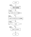
<両面プリント動作のフローチャート>
図3は本実施例の印字動作時のフローチャートである。エンジン制御部202は、1面目の/TOP信号を出力し1面目の印字動作を開始すると(ステップ600、以下S600のようにする)、1面目の用紙後端がレジセンサ22を抜けるタイミング、つまり、レジセンサ22の出力信号の立ち下がりを監視する(S601)。エンジン制御部202は、立ち下がりを検知してから、2面目の/TOP信号出力タイミングの計測を開始し(S602)、タイミングの到達、すなわちT1が経過したかを監視する(S603)。エンジン制御部202はT1が経過した時点で2面目の/TOP信号を出力する(S604)。
<Both-sided printing operation flowchart>
FIG. 3 is a flowchart during the printing operation of this embodiment. When the
以上述べたことにより、用紙の後端がレジセンサ22を抜けてから、用紙の2面目にトナー像を同期して二次転写することが可能な時間、経過した後にエンジン制御部202が2面目の/TOP信号を出力する。これにより、実際に給紙カセット1にセットされている用紙の搬送方向のサイズがコントローラ制御部201に指定されたサイズよりも大きい場合であっても、ジャムやプリントエラーを発生させることがない。かつ、給紙カセット1にセットされた用紙サイズに応じた最速スループットで両面プリントを行うことが可能となる。
As described above, after the lapse of a time during which the toner image can be secondarily transferred in synchronization with the second surface of the sheet after the trailing edge of the sheet has passed through the
なお、上述の実施例は本発明の趣旨に基づいて種々変更することが可能であり、これらを発明の範囲から排除するものではない。 The above-described embodiments can be variously modified based on the gist of the present invention, and these are not excluded from the scope of the invention.
実施例1は、画像形成を開始してからトナー像の先端が二次転写位置13に到達するまでの時間が、用紙の後端がレジセンサ22を抜けてから反転した後、反転後の用紙先端が二次転写位置13に到達するまでの時間よりも短い構成であった。この場合に、用紙の後端がレジセンサを抜けたタイミングに基づいて/TOP信号を出力して、プリントエラーを発生させず、セットされた用紙サイズに応じた最速スループットで両面プリントを行うことが可能にするものである。
In the first exemplary embodiment, the time from the start of image formation until the leading edge of the toner image reaches the
実施例2では、上記の時間関係が逆である場合、つまり、画像形成を開始してからトナー像の先端が二次転写位置13に到達するまでの時間が、用紙の後端がレジセンサ22を抜けてから反転した後、反転後の用紙先端が二次転写位置13に到達するまでの時間よりも長い構成を前提とする。このような構成において、用紙サイズに応じた最速スループット(図4における700の時間間隔を可能な限り短くすること)で両面プリントを行うことが可能な方法について説明する。具体的には、レジセンサ22よりも上流(搬送方向の上流側)に配置された搬送路上のセンサを利用する。この時、画像形成を開始してからトナー像の先端が二次転写位置13に到達するまでの時間は、このセンサにより用紙の後端を検出してからその用紙が反転し、反転後の用紙先端が二次転写位置13に到達するまでの時間よりも短くなるように配置される。本実施例においては、エンジン制御部202が、用紙の1面目の後端が前述の搬送路上のセンサを抜けたタイミングを基準に、2面目の/TOP信号を出力するタイミングを決定する。以降では、前述の搬送路上のセンサとして、給紙カセット1から給送された転写材2を検知する給紙センサ21を用いて説明する。なお、画像形成装置の構成は図8、図9と同様であり説明を省略し、以下同じ符号を用いて説明する。
In the second exemplary embodiment, when the above time relationship is reversed, that is, the time from the start of image formation until the leading edge of the toner image reaches the
<両面プリント時の基本動作>
図4は上記構成において、最速のスループットで両面プリントを実現する場合のタイミングチャートである。各タイミングは図1でのタイミングとほぼ同じであり、以降では本実施例における特徴的な部分のみについて説明する。なお、本実施例では給紙センサ21を用いるため、図4には給紙センサ21のタイミングチャートを追加して示している。この図を基に本実施例における2面目の/TOP信号出力タイミングについて説明する。
<Basic operation during duplex printing>
FIG. 4 is a timing chart in the case of realizing double-sided printing with the fastest throughput in the above configuration. Each timing is substantially the same as the timing in FIG. 1, and only the characteristic part in this embodiment will be described below. In this embodiment, since the
本実施例においても、図1に対応する図4におけるT2とT3はそれぞれ紙サイズによらず一定である。しかし、その関係は実施例1とは逆でT2<T3となる。 Also in this embodiment, T2 and T3 in FIG. 4 corresponding to FIG. 1 are constant regardless of the paper size. However, the relationship is opposite to that of the first embodiment and T2 <T3.
したがって、本実施例では、給紙センサ21を利用して2面目の/TOP信号の出力タイミングを制御する。
Therefore, in this embodiment, the
一方、1面目の画像形成時に用紙後端が給紙センサ21を抜けて(722)から、レジセンサ22を抜ける(702)までの時間は一定である。このため、給紙センサ21を抜けて(722)から、反転してレジセンサ22に到達する(712)までの時間T2’は用紙サイズによらず一定であり、T2’>T3となる。 On the other hand, the time from when the trailing edge of the paper passes through the paper feed sensor 21 (722) to when it passes through the registration sensor 22 (702) during the image formation on the first side is constant. For this reason, the time T2 'from passing through the paper feed sensor 21 (722) to inverting and reaching the registration sensor 22 (712) is constant regardless of the paper size, and T2'> T3.
したがって、本実施例では、2面目の/TOP信号出力タイミング(711)を、用紙が給紙センサ21を抜けたタイミング(722)から、T2’とT3の差であるT1’の時間だけ経過したタイミングとする。これにより、用紙サイズに応じた最速のスループットで両面プリントを行う。なお、T2’とT3は共に用紙サイズによらず一定であるため、T1’も一定となる。なお、701は1面目の/TOP信号が出力されるタイミングである。
Therefore, in the present embodiment, the / TOP signal output timing (711) on the second side has elapsed from the timing (722) when the sheet exits the
<用紙サイズが大きい場合の両面プリント時の動作>
図5は、実際に給紙カセット1にセットされている用紙の搬送方向のサイズがコントローラ制御部201に指定された用紙サイズよりも大きい場合に本実施例を適用した時の両面プリント動作のタイミングチャートである。
<Operations for duplex printing when the paper size is large>
FIG. 5 shows the timing of the duplex printing operation when the present embodiment is applied when the size in the transport direction of the paper actually set in the
エンジン制御部202は、1面目の/TOP信号を出力(811)し、給紙動作を開始(812)する。そして、ピックアップされた用紙の先端が給紙センサ21に到達(818)し、その後レジストローラ20に到達した時点(813)で、用紙搬送を一時停止(814)する。そして、中間転写ベルト12上に形成したトナー像に合わせて用紙搬送を再開(815)して、トナー像を用紙2に転写する。エンジン制御部202は、1面目の用紙後端が給紙センサ21を抜けて(819)からT1’(801)が経過したタイミングで2面目の/TOP信号を出力する(821)。
The
本実施例において、1面目の画像形成時に用紙後端が給紙センサ21を抜けて(819)から、レジセンサ22を抜ける(823)までの時間は一定である。このため、給紙センサ21を抜けて(819)から、反転してレジセンサ22に到達する(823)までの時間T2’は用紙サイズによらず一定であり、T2’>T3となる。したがって、本実施例では、2面目の/TOP信号出力タイミング(821)を、用紙が給紙センサ21を抜けたタイミング(819)から、T2’とT3の差であるT1’の時間だけ経過したタイミングとする。これにより、用紙サイズに応じた最速のスループットで両面プリントを行う。なお、T2’とT3は共に用紙サイズによらず一定であるため、T1’も一定となる。
In this embodiment, the time from when the trailing edge of the paper passes through the paper feed sensor 21 (819) to when it passes through the registration sensor 22 (823) during the image formation on the first side is constant. Therefore, the time T2 'from passing through the paper feed sensor 21 (819) to inverting and reaching the registration sensor 22 (823) is constant regardless of the paper size, and T2'> T3. Therefore, in the present embodiment, the / TOP signal output timing (821) on the second side has elapsed from the timing (819) when the sheet exits the
エンジン制御部202は、1面目の用紙後端が定着排紙センサ24を抜け(816)、用紙が反転可能な位置まで用紙2を搬送した後に反転(817)させ両面搬送路に引き込む。そして、2面目の用紙先端がレジストローラ20に到達した時点(823)で用紙搬送を一時停止(824)し、中間転写ベルト12上に形成したトナー像に合わせて、用紙搬送を再開(825)して、トナー像を用紙2に転写する。
The
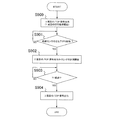
<両面プリント動作のフローチャート>
図6は本実施例の印字動作時のフローチャートである。
<Both-sided printing operation flowchart>
FIG. 6 is a flowchart during the printing operation of the present embodiment.
エンジン制御部202は、1面目の/TOP信号を出力し1面目の印字動作を開始すると(S900)、1面目の画像形成時に用紙後端が給紙センサ21を抜けるタイミング、つまり、給紙センサ21の出力信号の立ち下がりを監視する(S901)。エンジン制御部202は、立ち下がりを検知してから、2面目の/TOP信号出力タイミングの計測を開始し(S902)、タイミングの到達、すなわちT1’が経過したかを常に監視する(S903)。エンジン制御部202はT1’経過した時点で2面目の/TOP信号を出力する(S904)。
When the
以上述べたことにより、用紙の後端が給紙センサ21を抜けてから、2面目の用紙にトナー像を同期して二次転写することが可能な時間、経過した後にエンジン制御部202が2面目の/TOP信号を出力する。これにより、実際に給紙カセット1にセットされている用紙の搬送方向のサイズがコントローラ制御部201に指定されたサイズよりも大きい場合であってもジャムやプリントエラーを発生させない。かつ、給紙カセット1にセットされた用紙サイズに応じた最速スループットで両面プリントを行うことが可能となる。
As described above, after the lapse of a time during which the toner image can be secondarily transferred synchronously to the second sheet after the trailing edge of the sheet has passed through the
なお、上述の実施例は本発明の趣旨に基づいて種々変更することが可能であり、これらを発明の範囲から排除するものではない。 The above-described embodiments can be variously modified based on the gist of the present invention, and these are not excluded from the scope of the invention.
実施例1、実施例2では、用紙の搬送方向のサイズ(用紙サイズ)に着目した。そして、最速スループットを実現するための2面目の/TOP信号出力タイミングについて説明した。なお、このタイミングは、用紙サイズに基づく2面目/TOP信号出力タイミングであって、2面目の画像形成を開始するタイミングである。 In the first and second embodiments, attention is paid to the size (paper size) in the paper transport direction. The second surface / TOP signal output timing for realizing the fastest throughput has been described. This timing is the second side / TOP signal output timing based on the paper size, and is the timing at which image formation on the second side is started.
本実施例では、用紙サイズの他に、用紙の搬送方向に垂直な方向(主走査方向ともいう)のサイズ(以後「用紙幅」とする)も考慮した上で、最速スループットを実現するための2面目の/TOP信号出力タイミングについて説明する。なお、画像形成装置の構成は図8、図9と同様であり説明を省略し、以下同じ符号を用いて説明する。 In this embodiment, in addition to the paper size, the size (hereinafter referred to as “paper width”) in the direction perpendicular to the paper conveyance direction (hereinafter also referred to as “paper width”) is taken into consideration. The / TOP signal output timing on the second side will be described. The configuration of the image forming apparatus is the same as that shown in FIGS. 8 and 9 and will not be described.
用紙幅が狭い(転写材の搬送方向に垂直な方向の長さが所定の長さよりも短い)ときは定着器14に転写材が通過しない部分である非通紙部(端部ともいう)が温度上昇してしまう。このような場合、画像形成間隔を広げて、定着器14へ通紙しない時間を増やすことで端部の温度上昇を抑制する制御を行う(スループットダウン制御という)。この制御については公知であるため、詳細な説明は省略する。この制御を適用した場合の2面目の/TOP信号出力タイミングが用紙サイズに基づく2面目の/TOP信号出力タイミングよりも長い(遅いタイミングである)場合、2面目の/TOP信号出力は前者のタイミングまで遅らせる必要がある。なお、端部の温度上昇を抑制する制御を適用した場合の2面目の/TOP信号出力タイミングを「用紙幅に基づく2面目/TOP信号出力タイミング(画像形成を開始するタイミング)」とする。
When the sheet width is narrow (the length in the direction perpendicular to the transfer material conveyance direction is shorter than a predetermined length), a non-sheet-passing portion (also referred to as an end portion), which is a portion through which the transfer material does not pass through the fixing
以下の説明では、実施例1で説明した用紙後端がレジセンサ22を抜けてから所定時間経過後に2面目の/TOP信号を出力する場合を例に挙げて説明する。
In the following description, a case where the second side / TOP signal is output after a predetermined time has elapsed after the trailing edge of the sheet described in the first embodiment has passed through the
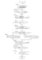
<両面プリント動作のフローチャート>
図7は本実施例の印字動作時のフローチャートである。
<Both-sided printing operation flowchart>
FIG. 7 is a flowchart during the printing operation of this embodiment.
エンジン制御部202は、1面目の/TOP信号を出力し1面目の印字動作を開始すると(S1000)、1面目の用紙後端がレジセンサ22を抜けるタイミング、つまり、レジセンサ22の立ち下がりを監視(S1001)する。エンジン制御部202は、立ち下がりを検知したタイミングで、用紙長要因の2面目の/TOP信号出力タイミングAを算出する(S1002)。
When the
その後、エンジン制御部202は、図示しない用紙幅を検知する紙幅センサの状態(紙幅センサオフ(OFF):紙幅が狭い)をチェックする(S1003)。ここで、紙幅センサがオンの場合、用紙幅は広いと判断し定着器14の端部での温度上昇は発生しないため、2面目の/TOP信号出力タイミングを、S1002で算出したAのタイミングに決定する(S1006)。一方、エンジン制御部202は、紙幅センサがオフである場合、用紙幅は狭いと判断し定着器14の端部での温度上昇が発生するため、用紙幅に基づく2面目の/TOP信号出力タイミングBを算出する(S1004)。そして、BのタイミングとAのタイミングを比較し(S1005)、Aのタイミングの方が遅い場合は2面目の/TOP信号出力タイミングを、S1002で算出したAのタイミングに決定する(S1006)。一方、Bのタイミングの方が遅い場合は2面目の/TOP信号出力タイミングを、S1004で算出したBのタイミングに決定する(S1007)。
Thereafter, the
エンジン制御部202は2面目の/TOP信号出力タイミングをS1006もしくはS1007で決定した後にタイミングの計測を開始し(S1008)、タイミングの到達を監視する(S1009)。そして、2面目の/TOP信号出力タイミングに到達した時点で2面目の/TOP信号を出力する(S1010)。
The
以上述べたことにより、用紙幅が狭い場合は、用紙の後端がレジセンサ22を抜けてから、用紙サイズと用紙幅を考慮した時間が経過した後に、エンジン制御部202が2面目の/TOP信号を出力する。これにより、実際に給紙カセット1にセットされている用紙の搬送方向のサイズがコントローラ制御部201に指定されたサイズよりも長い場合であっても、ジャムやプリントエラーを発生させない。かつ、定着器14の端部の温度上昇を抑制した上で、給紙カセット1にセットされた用紙に応じた最速スループットで両面プリントを行うことが可能となる。
As described above, when the paper width is narrow, the
なお、本実施例では、用紙後端がレジセンサ22を抜けてから所定時間経過後に2面目の/TOP信号を出力する場合を例に説明したが、本実施例は、実施例2で説明した用紙後端が給紙センサ21を抜けてから所定時間経過後に2面目の/TOP信号を出力する場合にも適用できる。この場合は、図7のS1001で、給紙センサ21の出力信号の立ち下がりを監視することになる。
In this embodiment, the case where the second side / TOP signal is output after a lapse of a predetermined time after the trailing edge of the sheet leaves the
Claims (11)
前記像担持体に形成された画像が転写される中間転写体と、
転写材に前記中間転写体上に形成された画像を転写する転写部と、
前記転写部により画像が転写される前に、搬送される転写材を検知する検知部と、
1面目に画像が形成された転写材を反転させ、再度、前記転写部に搬送する搬送部と、
指定された転写材の搬送方向のサイズに基づいて、前記画像形成部によって画像形成を開始するタイミングを制御する制御部と、
を備え、
前記制御部は、転写材の2面目に画像形成をする際の前記画像形成部によって画像形成を開始するタイミングを、指定された転写材の搬送方向のサイズと搬送された転写材の搬送方向のサイズに基づいて切り換えることを特徴とする画像形成装置。 An image forming unit that forms an image on an image carrier;
An intermediate transfer member to which an image formed on the image carrier is transferred;
A transfer part for transferring an image formed on the intermediate transfer member to a transfer material;
Before the image is transferred by the transfer unit, a detection unit that detects a transfer material conveyed;
A transfer unit that reverses the transfer material on which an image is formed on the first surface and conveys the transfer material to the transfer unit again;
A control unit that controls the timing of starting image formation by the image forming unit based on the size of the designated transfer material in the conveyance direction;
With
The control unit determines the timing at which image formation is started by the image forming unit when forming an image on the second surface of the transfer material in accordance with the size in the transfer direction of the designated transfer material and the transfer direction of the transferred transfer material. An image forming apparatus characterized by switching based on size.
指定された転写材の搬送方向のサイズよりも搬送された転写材の搬送方向のサイズが大きい場合に、前記検知部によって転写材の後端を検知したタイミングに基づき、転写材の2面目の画像形成を開始する前記タイミングを決定することを特徴とする請求項1に記載の画像形成装置。 When the size of the designated transfer material in the transport direction is the same as the size of the transported transfer material in the transport direction, the control unit determines the second surface of the transfer material based on the size of the designated transfer material. Determining the timing to start image formation of
When the size of the transfer material conveyed in the conveyance direction is larger than the designated size of the transfer material in the conveyance direction, the image on the second surface of the transfer material is determined based on the timing at which the detection unit detects the trailing edge of the transfer material. The image forming apparatus according to claim 1, wherein the timing for starting the formation is determined.
転写材の後端が前記給紙センサを通過してから反転されて、該転写材が転写部に搬送されるまでの時間が、前記画像形成部によって転写材の2面目の画像形成が開始されてから前記中間転写体に形成された画像が前記転写部に到達するまでの時間よりも長いことを特徴とする請求項1に記載の画像形成装置。 The detection unit is a paper feed sensor that detects a fed transfer material,
The time from when the rear end of the transfer material passes through the paper feed sensor is reversed and the transfer material is transported to the transfer unit, the image forming unit starts image formation on the second side of the transfer material. The image forming apparatus according to claim 1, wherein an image formed on the intermediate transfer member is longer than a time required to reach the transfer unit.
前記制御部は、前記検知部によって転写材の後端を検知したタイミングに基づき決定した、転写材の2面目の画像形成を開始する前記タイミングと、前記遅らせたタイミングとを比較し、いずれか遅い方のタイミングで前記2面目の画像形成を開始することを特徴とする請求項2に記載の画像形成装置。 The control unit further determines a timing of starting image formation by the image forming unit when the size in the direction perpendicular to the transfer material transport direction is shorter than a predetermined size. Switch to a timing that is later than the timing based on the size,
The control unit compares the timing for starting image formation on the second surface of the transfer material, which is determined based on the timing when the detection unit detects the trailing edge of the transfer material, with the delayed timing, whichever is later The image forming apparatus according to claim 2, wherein the image formation on the second surface is started at the timing of the first direction.
画像形成部により像担持体に形成された画像が転写される中間転写体と、
前記中間転写体に形成された画像を転写材に転写する転写部と、
前記転写部により画像が転写される前に、搬送される転写材を検知する検知部と、
1面目に画像が形成された転写材を反転させ、再度、前記転写部に搬送する両面搬送部と、
を備え、
転写材の2面目に画像形成をする際の前記画像形成部による画像形成のタイミングを、指定された転写材の搬送方向のサイズと搬送された転写材のサイズに基づいて切り換えることを特徴とする両面画像形成装置。 In a double-sided image forming apparatus that forms images on both sides of a transfer material,
An intermediate transfer member to which an image formed on the image carrier by the image forming unit is transferred;
A transfer portion for transferring an image formed on the intermediate transfer member to a transfer material;
Before the image is transferred by the transfer unit, a detection unit that detects a transfer material conveyed;
A double-sided conveyance unit that reverses the transfer material on which an image is formed on the first surface and conveys the transfer material to the transfer unit again;
With
The timing of image formation by the image forming unit when forming an image on the second surface of the transfer material is switched based on the size in the transport direction of the designated transfer material and the size of the transported transfer material. Double-sided image forming apparatus.
指定された転写材の搬送方向のサイズよりも搬送された転写材の搬送方向のサイズが大きい場合に、前記検知部によって転写材の後端を検知したタイミングに基づき、転写材の2面目の画像形成を開始する前記タイミングを決定することを特徴とする請求項7に記載の両面画像形成装置。 If the size of the specified transfer material in the transport direction is the same as the size of the transported transfer material in the transport direction, image formation of the second surface of the transfer material is started based on the size of the specified transfer material Determine the timing to
When the size of the transfer material conveyed in the conveyance direction is larger than the designated size of the transfer material in the conveyance direction, the image on the second surface of the transfer material is determined based on the timing at which the detection unit detects the trailing edge of the transfer material. The double-sided image forming apparatus according to claim 7, wherein the timing for starting the formation is determined.
転写材の後端が前記給紙センサを通過してから反転されて、該転写材が転写部に搬送されるまでの時間が、前記画像形成部によって転写材の2面目の画像形成が開始されてから前記中間転写体に形成された画像が前記転写部に到達するまでの時間よりも長いことを特徴とする請求項7に記載の両面画像形成装置。 The detection unit is a paper feed sensor that detects a fed transfer material,
The time from when the rear end of the transfer material passes through the paper feed sensor is reversed and the transfer material is transported to the transfer unit, the image forming unit starts image formation on the second side of the transfer material. The double-sided image forming apparatus according to claim 7, wherein an image formed on the intermediate transfer body is longer than a time required to reach the transfer portion.
前記検知部によって転写材の後端を検知したタイミングに基づき決定した、転写材の2面目の画像形成を開始する前記タイミングと、前記遅らせたタイミングとを比較し、いずれか遅い方のタイミングで前記2面目の画像形成を開始することを特徴とする請求項8に記載の両面画像形成装置。 Further, when it is determined that the size of the transfer material in the direction perpendicular to the conveyance direction is shorter than a predetermined size, the timing at which image formation is started by the image forming unit is based on the timing based on the designated transfer material size. Switch to a later timing,
The timing for starting image formation on the second surface of the transfer material, which is determined based on the timing at which the detection unit detects the trailing edge of the transfer material, is compared with the delayed timing, and the later timing is 9. The double-sided image forming apparatus according to claim 8, wherein image formation on the second side is started.
Priority Applications (2)
| Application Number | Priority Date | Filing Date | Title |
|---|---|---|---|
| JP2009117594A JP5355211B2 (en) | 2008-05-30 | 2009-05-14 | Image forming apparatus and double-sided image forming apparatus |
| US12/471,897 US8867982B2 (en) | 2008-05-30 | 2009-05-26 | Image forming apparatus and double-sided image forming apparatus |
Applications Claiming Priority (3)
| Application Number | Priority Date | Filing Date | Title |
|---|---|---|---|
| JP2008142836 | 2008-05-30 | ||
| JP2008142836 | 2008-05-30 | ||
| JP2009117594A JP5355211B2 (en) | 2008-05-30 | 2009-05-14 | Image forming apparatus and double-sided image forming apparatus |
Publications (3)
| Publication Number | Publication Date |
|---|---|
| JP2010009024A true JP2010009024A (en) | 2010-01-14 |
| JP2010009024A5 JP2010009024A5 (en) | 2012-06-28 |
| JP5355211B2 JP5355211B2 (en) | 2013-11-27 |
Family
ID=41379968
Family Applications (1)
| Application Number | Title | Priority Date | Filing Date |
|---|---|---|---|
| JP2009117594A Active JP5355211B2 (en) | 2008-05-30 | 2009-05-14 | Image forming apparatus and double-sided image forming apparatus |
Country Status (2)
| Country | Link |
|---|---|
| US (1) | US8867982B2 (en) |
| JP (1) | JP5355211B2 (en) |
Cited By (1)
| Publication number | Priority date | Publication date | Assignee | Title |
|---|---|---|---|---|
| JP2016075756A (en) * | 2014-10-03 | 2016-05-12 | キヤノン株式会社 | Image forming apparatus |
Families Citing this family (2)
| Publication number | Priority date | Publication date | Assignee | Title |
|---|---|---|---|---|
| CN107005620B (en) * | 2014-12-12 | 2019-06-21 | 佳能株式会社 | Copy device, the control method of copy device and storage medium |
| EP3776090B1 (en) * | 2018-04-04 | 2022-05-11 | Canon Production Printing Holding B.V. | Duplex printing method with shrinkage compensation |
Citations (7)
| Publication number | Priority date | Publication date | Assignee | Title |
|---|---|---|---|---|
| JPS63300247A (en) * | 1987-05-30 | 1988-12-07 | Canon Inc | Image forming device |
| JPH10319675A (en) * | 1997-05-19 | 1998-12-04 | Ricoh Co Ltd | Color image forming device |
| JP2002244524A (en) * | 2001-02-16 | 2002-08-30 | Ricoh Co Ltd | Image forming device |
| JP2003015464A (en) * | 2001-06-29 | 2003-01-17 | Canon Inc | Image forming device |
| JP2003035974A (en) * | 2001-07-25 | 2003-02-07 | Canon Inc | Image forming device |
| JP2003076081A (en) * | 2001-09-05 | 2003-03-14 | Canon Inc | Image forming device |
| JP2006030504A (en) * | 2004-07-15 | 2006-02-02 | Kyocera Mita Corp | Image forming apparatus |
Family Cites Families (6)
| Publication number | Priority date | Publication date | Assignee | Title |
|---|---|---|---|---|
| JPH10194529A (en) | 1996-12-30 | 1998-07-28 | Canon Inc | Image forming device and system |
| US6996360B2 (en) * | 2002-09-27 | 2006-02-07 | Seiko Epson Corporation | Apparatus and method of transferring image on intermediate medium onto recording medium |
| US6813451B2 (en) * | 2002-10-30 | 2004-11-02 | Hewlett-Packard Development Company, L.P. | Duplex image registration |
| JP4111026B2 (en) * | 2003-03-24 | 2008-07-02 | 富士ゼロックス株式会社 | Image forming apparatus |
| JP4234150B2 (en) * | 2005-07-08 | 2009-03-04 | シャープ株式会社 | Image recording system |
| JP2007065411A (en) | 2005-08-31 | 2007-03-15 | Canon Finetech Inc | Image forming apparatus |
-
2009
- 2009-05-14 JP JP2009117594A patent/JP5355211B2/en active Active
- 2009-05-26 US US12/471,897 patent/US8867982B2/en active Active
Patent Citations (7)
| Publication number | Priority date | Publication date | Assignee | Title |
|---|---|---|---|---|
| JPS63300247A (en) * | 1987-05-30 | 1988-12-07 | Canon Inc | Image forming device |
| JPH10319675A (en) * | 1997-05-19 | 1998-12-04 | Ricoh Co Ltd | Color image forming device |
| JP2002244524A (en) * | 2001-02-16 | 2002-08-30 | Ricoh Co Ltd | Image forming device |
| JP2003015464A (en) * | 2001-06-29 | 2003-01-17 | Canon Inc | Image forming device |
| JP2003035974A (en) * | 2001-07-25 | 2003-02-07 | Canon Inc | Image forming device |
| JP2003076081A (en) * | 2001-09-05 | 2003-03-14 | Canon Inc | Image forming device |
| JP2006030504A (en) * | 2004-07-15 | 2006-02-02 | Kyocera Mita Corp | Image forming apparatus |
Cited By (1)
| Publication number | Priority date | Publication date | Assignee | Title |
|---|---|---|---|---|
| JP2016075756A (en) * | 2014-10-03 | 2016-05-12 | キヤノン株式会社 | Image forming apparatus |
Also Published As
| Publication number | Publication date |
|---|---|
| US8867982B2 (en) | 2014-10-21 |
| JP5355211B2 (en) | 2013-11-27 |
| US20090297173A1 (en) | 2009-12-03 |
Similar Documents
| Publication | Publication Date | Title |
|---|---|---|
| RU2367016C2 (en) | Image forming device | |
| EP1672434B1 (en) | Image forming apparatus and its control method for duplex printing in the case of paper feed fault | |
| JP2009078886A (en) | Printing system | |
| JP4933148B2 (en) | Image forming apparatus | |
| JP5355211B2 (en) | Image forming apparatus and double-sided image forming apparatus | |
| JP5072238B2 (en) | Image forming apparatus | |
| JP2009103832A (en) | Image forming apparatus and control method for same | |
| JP2008122935A (en) | Image forming apparatus | |
| JP7277246B2 (en) | image forming device | |
| JP2008020902A (en) | Image forming apparatus | |
| JP4425752B2 (en) | Image forming apparatus | |
| JP5414923B2 (en) | Image forming apparatus | |
| JP2012053390A (en) | Image forming device | |
| JP2007102090A (en) | Image forming apparatus | |
| JP2003076081A (en) | Image forming device | |
| JP2006015515A (en) | Image forming device | |
| JP2009214979A (en) | Image forming device | |
| JP2005084307A (en) | Image forming apparatus | |
| JP2005077453A (en) | Color image forming apparatus | |
| JP2017078815A (en) | Image forming apparatus | |
| JP4848816B2 (en) | Recording medium transport device | |
| JP2010111062A (en) | Image forming system and program | |
| JP2001142374A (en) | Image forming device | |
| JP2002049187A (en) | Image forming device | |
| JP2019045619A (en) | Image formation apparatus |
Legal Events
| Date | Code | Title | Description |
|---|---|---|---|
| RD05 | Notification of revocation of power of attorney |
Free format text: JAPANESE INTERMEDIATE CODE: A7425 Effective date: 20120125 |
|
| RD03 | Notification of appointment of power of attorney |
Free format text: JAPANESE INTERMEDIATE CODE: A7423 Effective date: 20120208 |
|
| A521 | Written amendment |
Free format text: JAPANESE INTERMEDIATE CODE: A523 Effective date: 20120510 |
|
| A621 | Written request for application examination |
Free format text: JAPANESE INTERMEDIATE CODE: A621 Effective date: 20120510 |
|
| A131 | Notification of reasons for refusal |
Free format text: JAPANESE INTERMEDIATE CODE: A131 Effective date: 20130319 |
|
| A977 | Report on retrieval |
Free format text: JAPANESE INTERMEDIATE CODE: A971007 Effective date: 20130321 |
|
| A521 | Written amendment |
Free format text: JAPANESE INTERMEDIATE CODE: A523 Effective date: 20130517 |
|
| TRDD | Decision of grant or rejection written | ||
| A01 | Written decision to grant a patent or to grant a registration (utility model) |
Free format text: JAPANESE INTERMEDIATE CODE: A01 Effective date: 20130730 |
|
| A61 | First payment of annual fees (during grant procedure) |
Free format text: JAPANESE INTERMEDIATE CODE: A61 Effective date: 20130827 |
|
| R151 | Written notification of patent or utility model registration |
Ref document number: 5355211 Country of ref document: JP Free format text: JAPANESE INTERMEDIATE CODE: R151 |