JP2010008419A - Multistage proof mass movement deceleration within mems structure - Google Patents
Multistage proof mass movement deceleration within mems structure Download PDFInfo
- Publication number
- JP2010008419A JP2010008419A JP2009151134A JP2009151134A JP2010008419A JP 2010008419 A JP2010008419 A JP 2010008419A JP 2009151134 A JP2009151134 A JP 2009151134A JP 2009151134 A JP2009151134 A JP 2009151134A JP 2010008419 A JP2010008419 A JP 2010008419A
- Authority
- JP
- Japan
- Prior art keywords
- proof mass
- comb
- motor
- deceleration
- substrate
- Prior art date
- Legal status (The legal status is an assumption and is not a legal conclusion. Google has not performed a legal analysis and makes no representation as to the accuracy of the status listed.)
- Granted
Links
Images
Classifications
-
- G—PHYSICS
- G01—MEASURING; TESTING
- G01C—MEASURING DISTANCES, LEVELS OR BEARINGS; SURVEYING; NAVIGATION; GYROSCOPIC INSTRUMENTS; PHOTOGRAMMETRY OR VIDEOGRAMMETRY
- G01C19/00—Gyroscopes; Turn-sensitive devices using vibrating masses; Turn-sensitive devices without moving masses; Measuring angular rate using gyroscopic effects
- G01C19/56—Turn-sensitive devices using vibrating masses, e.g. vibratory angular rate sensors based on Coriolis forces
- G01C19/5719—Turn-sensitive devices using vibrating masses, e.g. vibratory angular rate sensors based on Coriolis forces using planar vibrating masses driven in a translation vibration along an axis
-
- B—PERFORMING OPERATIONS; TRANSPORTING
- B81—MICROSTRUCTURAL TECHNOLOGY
- B81B—MICROSTRUCTURAL DEVICES OR SYSTEMS, e.g. MICROMECHANICAL DEVICES
- B81B7/00—Microstructural systems; Auxiliary parts of microstructural devices or systems
- B81B7/02—Microstructural systems; Auxiliary parts of microstructural devices or systems containing distinct electrical or optical devices of particular relevance for their function, e.g. microelectro-mechanical systems [MEMS]
-
- B—PERFORMING OPERATIONS; TRANSPORTING
- B81—MICROSTRUCTURAL TECHNOLOGY
- B81B—MICROSTRUCTURAL DEVICES OR SYSTEMS, e.g. MICROMECHANICAL DEVICES
- B81B3/00—Devices comprising flexible or deformable elements, e.g. comprising elastic tongues or membranes
- B81B3/0035—Constitution or structural means for controlling the movement of the flexible or deformable elements
- B81B3/0051—For defining the movement, i.e. structures that guide or limit the movement of an element
-
- B—PERFORMING OPERATIONS; TRANSPORTING
- B81—MICROSTRUCTURAL TECHNOLOGY
- B81B—MICROSTRUCTURAL DEVICES OR SYSTEMS, e.g. MICROMECHANICAL DEVICES
- B81B2201/00—Specific applications of microelectromechanical systems
- B81B2201/02—Sensors
- B81B2201/0228—Inertial sensors
- B81B2201/0235—Accelerometers
Abstract
Description
微小電子機械システム(MEMS)は、微細加工技術を使用して、電気的かつ機械的構成要素を同じ基板、たとえばシリコン基板上に組み込む。電気的構成要素は、集積回路プロセスを使用して製作され、一方、機械的構成要素は、集積回路プロセスに適合する微細機械加工プロセスを使用して製作される。この組合せにより、標準的な製造プロセスを使用して、システム全体をチップ上に製作することが可能になる。 Microelectromechanical systems (MEMS) use microfabrication techniques to incorporate electrical and mechanical components on the same substrate, such as a silicon substrate. The electrical components are fabricated using an integrated circuit process, while the mechanical components are fabricated using a micromachining process that is compatible with the integrated circuit process. This combination allows the entire system to be fabricated on a chip using standard manufacturing processes.
MEMSデバイスの共通の適用分野の1つは、センサデバイスの設計および製造である。センサデバイスの機械的部分は、感知能力を提供し、一方、センサデバイスの電気的部分は、機械的部分から受け取った情報を処理する。MEMSデバイスの一例は、ジャイロスコープである。一部の慣性測定ユニット(IMU)は、1つまたは複数のMEMSジャイロスコープを組み込む。 One common application area for MEMS devices is the design and manufacture of sensor devices. The mechanical portion of the sensor device provides sensing capability, while the electrical portion of the sensor device processes information received from the mechanical portion. An example of a MEMS device is a gyroscope. Some inertial measurement units (IMUs) incorporate one or more MEMS gyroscopes.
1つの知られたタイプのMEMSジャイロスコープは、振動素子を使用して、コリオリの加速度の検出によって角速度を感知する。この振動素子は、モータモードと呼ばれる共振振動モードで、基板に平行なモータ(X)軸に沿った振動運動の状態に入る。振動素子が運動状態になると、ジャイロスコープは、基板に垂直な入力(Z)軸の周りを基板が回転することによって引き起こされる角速度を検出することが可能になる。同じくXとZ軸の両方に垂直な感知(Y)軸に沿ってコリオリの加速度が生じ、感知モードと呼ばれる共振モードで、Y軸に沿った振動運動を発生させる。感知モードの振動の振幅は、基板の角速度に比例する。しかし、振動素子は、外力の作用を受けることがある。一例として、航空機または他の飛行機は、大きな重力の動作を行うことがある。これらの力により、MEMSデバイス、たとえばMEMSジャイロスコープ内のプルーフマスは、モータ駆動、モータピックオフ、または感知プレートに対して、時には上に挙げた構成要素のうちの1つまたは複数を損傷する恐れがあるほど高速で接触する可能性がある。そのような接触は、望ましくなく、MEMSデバイスの性能に影響を及ぼす。 One known type of MEMS gyroscope uses a vibrating element to sense angular velocity by detecting Coriolis acceleration. This vibration element enters a state of vibration motion along a motor (X) axis parallel to the substrate in a resonance vibration mode called a motor mode. When the oscillating element is in motion, the gyroscope can detect the angular velocity caused by the rotation of the substrate about the input (Z) axis perpendicular to the substrate. Similarly, Coriolis acceleration occurs along the sense (Y) axis that is perpendicular to both the X and Z axes, and generates a vibrating motion along the Y axis in a resonant mode called the sense mode. The amplitude of vibration in the sensing mode is proportional to the angular velocity of the substrate. However, the vibration element may be subjected to an external force. As an example, an aircraft or other airplane may perform large gravity movements. These forces can cause a proof mass in a MEMS device, such as a MEMS gyroscope, to damage one or more of the components listed above, sometimes to a motor drive, motor pickoff, or sensing plate. There is a possibility of contact at high speed. Such contact is undesirable and affects the performance of the MEMS device.
一実施形態では、微小電子機械システム(MEMS)デバイスは、少なくとも1つの固定具を備える基板と、そこから延びる第1および第2の減速延長部を有するプルーフマスと、モータ駆動櫛と、モータ感知櫛と、基板の上でモータ駆動櫛とモータ感知櫛との間にプルーフマスを懸架するように構成された複数の懸架部とを含む。懸架部は、基板に固定される。本体は、基板に取り付けられる。少なくとも1つの減速梁が、前記本体の第1の側面から延びる。この少なくとも1つの減速梁は、第1および第2の減速延長部のうちの少なくとも1つに係合し、かつ、プルーフマスがモータ駆動櫛およびモータ感知櫛に接触する前に、このプルーフマスを減速または停止させるように構成される。 In one embodiment, a microelectromechanical system (MEMS) device includes a substrate comprising at least one fixture, a proof mass having first and second deceleration extensions extending therefrom, a motor driven comb, and motor sensing. And a plurality of suspension portions configured to suspend the proof mass between the motor driving comb and the motor sensing comb on the substrate. The suspension is fixed to the substrate. The body is attached to the substrate. At least one deceleration beam extends from the first side of the body. The at least one deceleration beam engages at least one of the first and second deceleration extensions and before the proof mass contacts the motor drive comb and the motor sensing comb, Configured to slow down or stop.
本発明の好ましい代替実施形態について、次の図面を参照して、以下に詳細に説明する。 Preferred alternative embodiments of the present invention are described in detail below with reference to the following drawings.
本発明の実施形態は、本出願人が所有する米国特許第6865944号に記載の構造および/または概念を利用することができる。同特許の全体を、参照により本明細書に組み込む。 Embodiments of the present invention can utilize the structure and / or concepts described in commonly owned US Pat. No. 6,865,944. The entirety of that patent is incorporated herein by reference.
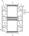
図1は、微小電子機械システム(MEMS)デバイス10、たとえばジャイロスコープの平面図を示す。MEMSデバイス10は、基板(図示せず)上に形成され、少なくとも1つのプルーフマス12と、プルーフマス12を支持するための複数の懸架部14と、懸架部14に接続された少なくとも1つの横梁16とを含む。代替構成では、懸架部14は、個別にかつ直接基板に接続される。MEMSデバイス10はまた、モータ駆動櫛18と、モータピックオフ櫛20と、および感知プレート22とを含み、これらは、個々のプルーフマス12に対応する。
FIG. 1 shows a plan view of a microelectromechanical system (MEMS) device 10, such as a gyroscope. The MEMS device 10 is formed on a substrate (not shown) and includes at least one
プルーフマス12は、MEMSデバイスでの使用に適した任意のマスから製作される。一実施形態では、プルーフマス12は、1枚のシリコン板である。微細機械加工技法に適合する他の材料を利用することもできる。図1は2つのプルーフマス12を示すが、2つ未満または3つ以上のプルーフマスを利用するMEMSデバイスを利用することもできる。
プルーフマス12は、実質上、モータ駆動櫛18とモータピックオフ櫛20との間に配置される。プルーフマス12は、複数の櫛状電極26を含む。電極26の一部分は、モータ駆動櫛18の方へ延び、電極26の一部分は、モータピックオフ櫛20の方へ延びる。図示の実施形態では、プルーフマス12は34個の電極26を有するが、異なる数の電極を組み込むプルーフマスを利用することも知られている。MEMSデバイス(図示せず)の他の実施形態では、モータ駆動櫛およびモータピックオフ櫛は、互いに隣接して配置することができる。
The
図示の実施形態では、プルーフマス12は、懸架部14によってそれぞれの感知プレート22の上に支持される。各プルーフマス12を懸架するために4つの懸架部14を示すが、プルーフマス12を適切に支持する任意の数の懸架部14を利用することができる。一実施形態では、懸架部14は、シリコンウェーハから微細機械加工された梁である。懸架部14はまた、図1に示すように、プルーフマス12を駆動面(X軸)および感知面(Y軸)内で動かすばねとして働く。
In the illustrated embodiment, the
モータ駆動櫛18は、それぞれのプルーフマス12の方へ延びる複数の櫛状電極28を含む。モータ駆動櫛18は18個の電極28を有するものとして示すが、モータ駆動櫛18上の電極28の数は通常、それぞれのプルーフマス12上の電極26の数によって決定される。モータ駆動櫛は通常、駆動電子機器(図1には図示せず)に接続される。電極26および電極28は、それぞれプルーフマス12およびモータ駆動櫛18から延びるにつれて互いにかみ合ってコンデンサを形成し、これらのコンデンサを利用して、駆動面(X軸)での運動を引き起こす。
The motor driven
モータピックオフ櫛20はまた、それぞれのプルーフマス12の方へ延びる複数の櫛状電極30を含む。モータピックオフ櫛20は18個の電極30を有するものとして示すが、モータピックオフ櫛20から延びる電極30の数は通常、それぞれのプルーフマス12上の電極26の数によって決定される。モータピックオフ櫛20は、感知櫛と呼ばれることがある。電極26および電極30は、それぞれプルーフマス12およびモータピックオフ櫛20から延びるにつれて互いにかみ合ってコンデンサを形成し、これらのコンデンサを利用して、駆動面(X軸)での運動を感知する。
The motor pickoff comb 20 also includes a plurality of comb-
感知プレート22は、それぞれのプルーフマス12に平行であり、コンデンサを形成する。少なくとも1つのプルーフマス12が駆動面(X軸)に沿って振動している間に、入力ベクトル(Z軸)に沿ってジャイロスコープとして動作するMEMSデバイス10に角速度(すなわち、航空機の回転)がかけられた場合、感知面(Y軸)でコリオリの加速度が検出される。感知面(Y軸)の運動を感知するには、静電容量が使用される。MEMSデバイス10の出力は通常、運動によって生じる静電容量の変化に比例する信号である。感知プレート22は通常、図1には図示しない感知電子機器に接続される。感知電子機器は、プルーフマス12がそれぞれの感知プレート22ならびにそれぞれのモータ駆動櫛18およびモータピックオフ櫛20の方へおよび/またはそれらから離れて動くとき、静電容量の変化を検出する。
The
モータピックオフ櫛20は通常、プルーフマス12の運動を感知する際に使用されるバイアス電圧(図示せず)に接続される。モータ駆動櫛18は通常、駆動電子機器(図示せず)に接続される。駆動電子機器により、プルーフマス12およびモータ駆動櫛18の複数の互いにかみ合った櫛状電極26、28によって形成されたコンデンサを使用することによって、それぞれのプルーフマス12を、駆動面(X軸)に沿って実質上音叉の周波数で振動させる。MEMSデバイス10は、密接して配置された2つの振動モードを有する。これらのモードのうちの1つは、モータモードと呼ばれることがあり、静電力によってデバイス10の共振周波数で駆動されて、振幅が比較的大きな振動を発生させる。モータモードでは、デバイス10に回転力がかけられると、プルーフマス12の速度に比例するコリオリの力が発生する。コリオリの力は、モータモードの周波数で、感知モード方向にプルーフマス12を駆動する。以下に説明するように、静電容量を利用して感知モードで振動を検出するために、1つまたは複数の電極が設けられる。感知電極に直流および/または交流バイアス電圧が印加され、その結果、感知モードでのプルーフマス12の運動により、出力電流を発生させる。
The motor pickoff comb 20 is typically connected to a bias voltage (not shown) that is used in sensing movement of the
特定の動作環境では、MEMSデバイス、たとえばジャイロスコープは、極度の衝撃および振動の作用を受けやすいが、微小な角速度および直線加速度を測定するのに十分な高さの機械的な感度ももたなければならない。そのような力は、プルーフマス12の延長部26を、モータ駆動櫛18、その延長部28、モータピックオフ櫛20、およびその延長部30のうちの1つまたは複数と強制的に接触させる可能性がある。延長部26、28、および30のうちの1つまたは複数が折れ、または他の形で損傷する可能性に加えて、静電力により、プルーフマス12は、プルーフマス12が接触したデバイス10の構成要素と物理的に接触したままになる可能性がある。他の力は、プルーフマス12の本体を感知プレート22に接触させる可能性がある。この場合も、静電力により、プルーフマス12は、感知プレート22に接触したままになる可能性がある。
In certain operating environments, MEMS devices, such as gyroscopes, are susceptible to extreme shock and vibration, but must also have mechanical sensitivity high enough to measure minute angular velocities and linear accelerations. I must. Such forces can force the
MEMSデバイス10はまた、過度の機械的外力によって生じる前述の動作上の問題を軽減または緩和させる複数の減速止め50を備えるように構成される。デバイス10は、減速止め50を利用して、外力から保護する。プルーフマス12はさらに、左プルーフマス54および右プルーフマス56として区別される。本明細書では、「左」および「右」という用語は、減速止め50の動作について説明するためだけの図に関する例示的な目的のものであり、MEMSデバイス10のいかなる種類の構造上の制限も示唆するものではない。左プルーフマス54および右プルーフマス56は、前述のように、懸架部14によって基板の上に支持される。懸架部14は、通常感知プレート(図示せず)が上部に取り付けられた基板(図示せず)の上にプルーフマス54および56を懸架するが、一方、懸架部14はまた、バイアス電圧が印加されると、プルーフマス54および56を振動させる。プルーフマス54および56が振動するにつれて、延長部26は、モータ駆動櫛18の延長部28とモータピックオフ櫛20の延長部30との間を前後に動き、それにより、静電容量の変化が生じ、この変化を定量化することができる。
The MEMS device 10 is also configured with a plurality of decelerator stops 50 that reduce or alleviate the aforementioned operational problems caused by excessive mechanical external forces. The device 10 uses the
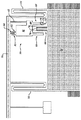
図2は、左プルーフマス54がモータ駆動櫛18およびモータ感知櫛20に接触するのを防止するように動作する減速止め50を詳細に示す図である。左プルーフマス54を参照して、単一の減速止め50について図示しかつ説明するが、この説明は、任意のプルーフマス(右プルーフマス56を含む)と併せて利用される減速止めにも当てはまること、および複数の減速止め50を任意の個々のプルーフマス(図1に示す)に関連させることができることを理解されたい。
FIG. 2 shows in detail the
減速止め50は本体60を含み、本体60は、一実施形態では、横梁16とプルーフマス54との間に配置され、かつ固定延長部62によって横梁16に取り付けられる。一実施形態では、本体60は、基板に取り付けられ、MEMSデバイスを固定する機能を提供する。図2に示すように、一実施形態では、懸架部にばねのような機能を与えるために、懸架部14は、回旋状またはヘビ状の構成を有することができる。
The
さらに、複数の減速梁64が、本体60からプルーフマス54の方へ延びる。図2に示すように、一実施形態では、梁64のうちの1つまたは複数は、それぞれの間隙74によって互いに隔てられた、均一なまたは様々な幅の複数の叉70、72を含むことができる。
In addition, a plurality of deceleration beams 64 extend from the
減速梁64間に配置された少なくとも1つの減速延長部66は、プルーフマス54から延びる。図2に示すように、一実施形態では、延長部66は、間隙74に類似するそれぞれの間隙によって互いに隔てられた、均一なまたは様々な幅の複数の叉76、78、80を含むことができる。
At least one
図2さらに示すように、一実施形態では、追加の複数の減速梁82が、本体60から延び、追加の減速延長部84が、横梁16から延びる。梁82および延長部84は、減速梁64および減速延長部66を参照して前述したように、先を叉状に分けることができる。
As further shown in FIG. 2, in one embodiment, an additional plurality of deceleration beams 82 extends from the
減速梁64、82、減速延長部66、84、およびヘビ状の懸架部14は、正常な運動条件下でプルーフマス54を自由に動かすが、プルーフマス54の運動が特定の制限を超えると、プルーフマス54を減速させるように働く。一実施形態では、プルーフマス54が櫛28および30に対して位置決めされるのに比べて、減速梁64、82は、延長部66、84に対してより近接して位置決めされる。図1および2に示すように、一実施形態では、減速梁64、82および減速延長部66、84は、細長い方形の構造である。
The deceleration beams 64, 82, the
具体的に言うと、プルーフマス54の運動により、減速延長部66、84のうちの1つまたは複数が減速梁64、82のうちの1つまたは複数に係合するとき、外力のために、減速梁64、82および減速延長部66、84のうちの1つまたは複数が湾曲して、プルーフマス54を減速させ、それによって、プルーフマス54が固定の止めに接触したとき、衝撃を著しく軽減させまたは除去する。減速止め50によってプルーフマス54が減速することで、プルーフマス54、モータ駆動櫛18、およびモータピックオフ櫛20の互いにかみ合った部材の損傷を防止する。さらに、梁64、82および/または延長部66、84の先を叉状に分けた構成により、プルーフマス54の減速は、連続して段階的に発生する。すなわち、たとえば、プルーフマス54が図2の右側へ突然動いたとき、叉80と叉70は互いに係合し、かつ叉78および叉72が湾曲する前に湾曲することができ、おそらく、叉78および叉72が湾曲する必要をなくすことができる。
Specifically, due to the external force when one or more of the
前述のように、本発明の好ましい実施形態について図示しかつ説明してきたが、本発明の精神および範囲から逸脱することなく、多くの変更を加えることができる。したがって、本発明の範囲は、好ましい実施形態の開示によって限定されるものではない。代わりに、本発明は、以下の特許請求の範囲への参照によってすべて決定されるべきである。 While the preferred embodiment of the invention has been illustrated and described, as noted above, many changes can be made without departing from the spirit and scope of the invention. Accordingly, the scope of the invention is not limited by the disclosure of the preferred embodiment. Instead, the invention should be determined entirely by reference to the following claims.
10 微小電子機械システム(MEMS)デバイス
12 プルーフマス
14 懸架部
16 横梁
18 モータ駆動櫛
20 モータピックオフ櫛、モータ感知櫛
22 感知プレート
26 櫛状電極、延長部
28 櫛状電極、延長部、櫛
30 櫛状電極、延長部、櫛
50 減速止め
54 左プルーフマス
56 右プルーフマス
60 本体
62 固定延長部
64 減速梁
66 減速延長部
70 叉
72 叉
74 間隙
76 叉
78 叉
80 叉
82 減速梁
84 減速延長部
DESCRIPTION OF SYMBOLS 10 Microelectromechanical system (MEMS)
Claims (3)
プルーフマス(12)であって、前記プルーフマス(12)から延びる第1および第2の減速延長部(50)を備えるプルーフマス(12)と、
モータ駆動櫛(18)と、
モータ感知櫛(20)と、
前記基板の上で前記モータ駆動櫛(18)と前記モータ感知櫛(20)との間に前記プルーフマス(12)を懸架するように構成された複数の懸架部(14)であって、前記基板に固定された、懸架部(14)と、
前記基板に取り付けられた本体(60)と、
前記本体(60)の第1の側面から延びる少なくとも1つの減速梁(64)であって、前記少なくとも1つの減速梁(64)が、前記第1および第2の減速延長部(50)のうちの少なくとも1つに係合し、かつ、前記プルーフマス(12)が前記モータ駆動櫛(18)および前記モータ感知櫛(20)に接触する前に、前記プルーフマス(12)を減速または停止させるように構成された、減速梁(64)と
を備える微小電子機械システム(MEMS)デバイス(10)。 A substrate comprising at least one fixture;
A proof mass (12) comprising first and second deceleration extensions (50) extending from said proof mass (12);
A motor driven comb (18);
A motor sensing comb (20);
A plurality of suspension portions (14) configured to suspend the proof mass (12) between the motor driving comb (18) and the motor sensing comb (20) on the substrate, A suspension (14) fixed to the substrate;
A body (60) attached to the substrate;
At least one reduction beam (64) extending from a first side of the body (60), wherein the at least one reduction beam (64) is one of the first and second reduction extensions (50). And the proof mass (12) is decelerated or stopped before the proof mass (12) contacts the motor drive comb (18) and the motor sensing comb (20). A microelectromechanical system (MEMS) device (10) comprising a deceleration beam (64) configured as follows.
前記第1および第2の減速延長部の第1の側面に配置され、かつ第1の方向の前記プルーフマスの運動を減速または停止させるように構成された、第1および第2の減速梁と、
前記第1および第2の減速延長部の第2の側面に配置され、かつ第2の方向の前記プルーフマスの運動を減速または停止させるように構成された、第3および第4の減速梁とを備える、請求項1に記載のデバイス。 The at least one deceleration beam is
First and second deceleration beams disposed on first sides of the first and second deceleration extensions and configured to decelerate or stop movement of the proof mass in a first direction; ,
Third and fourth deceleration beams disposed on second sides of the first and second deceleration extensions and configured to decelerate or stop movement of the proof mass in a second direction; The device of claim 1, comprising:
Applications Claiming Priority (2)
| Application Number | Priority Date | Filing Date | Title |
|---|---|---|---|
| US12/147,354 | 2008-06-26 | ||
| US12/147,354 US8011247B2 (en) | 2008-06-26 | 2008-06-26 | Multistage proof-mass movement deceleration within MEMS structures |
Publications (2)
| Publication Number | Publication Date |
|---|---|
| JP2010008419A true JP2010008419A (en) | 2010-01-14 |
| JP5400495B2 JP5400495B2 (en) | 2014-01-29 |
Family
ID=41138969
Family Applications (1)
| Application Number | Title | Priority Date | Filing Date |
|---|---|---|---|
| JP2009151134A Expired - Fee Related JP5400495B2 (en) | 2008-06-26 | 2009-06-25 | Multi-stage proof mass motion deceleration in MEMS structures |
Country Status (5)
| Country | Link |
|---|---|
| US (1) | US8011247B2 (en) |
| EP (1) | EP2146182B1 (en) |
| JP (1) | JP5400495B2 (en) |
| KR (1) | KR20100002228A (en) |
| AT (1) | ATE533028T1 (en) |
Families Citing this family (20)
| Publication number | Priority date | Publication date | Assignee | Title |
|---|---|---|---|---|
| US8516891B2 (en) * | 2007-01-16 | 2013-08-27 | Analog Devices, Inc. | Multi-stage stopper system for MEMS devices |
| US9171964B2 (en) | 2010-11-23 | 2015-10-27 | Honeywell International Inc. | Systems and methods for a three-layer chip-scale MEMS device |
| US8748206B2 (en) | 2010-11-23 | 2014-06-10 | Honeywell International Inc. | Systems and methods for a four-layer chip-scale MEMS device |
| US8776601B2 (en) | 2010-11-23 | 2014-07-15 | Honeywell International Inc. | MEMS sensor using multi-layer movable combs |
| US9493344B2 (en) | 2010-11-23 | 2016-11-15 | Honeywell International Inc. | MEMS vertical comb structure with linear drive/pickoff |
| CN102147423B (en) * | 2011-02-25 | 2012-06-13 | 东南大学 | Dual-axle integrated fully-coupled silicon micro-resonance type accelerometer |
| US20140260613A1 (en) * | 2013-03-15 | 2014-09-18 | Invensense, Inc. | Elastic bump stops for mems devices |
| CN103145093B (en) * | 2013-03-18 | 2015-04-08 | 厦门大学 | Preparation method of comb tooth clearance silicon micro-inertial component with high depth-to-width ratio |
| US9534896B2 (en) * | 2013-03-27 | 2017-01-03 | Honeywell International Inc. | Oscillating voltage of sense electrodes in a MEMS tuning fork gyroscope |
| US9476712B2 (en) | 2013-07-31 | 2016-10-25 | Honeywell International Inc. | MEMS device mechanism enhancement for robust operation through severe shock and acceleration |
| JP2015123526A (en) * | 2013-12-26 | 2015-07-06 | ソニー株式会社 | Function element, acceleration sensor, and switch |
| US10330471B2 (en) * | 2014-11-27 | 2019-06-25 | Goertek, Inc. | Triaxial micro-electromechanical gyroscope |
| JP6400621B2 (en) * | 2016-03-16 | 2018-10-03 | 株式会社東芝 | Angular velocity acquisition device and electronic component for angular velocity acquisition |
| JP6562878B2 (en) * | 2016-06-30 | 2019-08-21 | 株式会社東芝 | Angular velocity acquisition device |
| DE102016214962A1 (en) * | 2016-08-11 | 2018-02-15 | Robert Bosch Gmbh | Micromechanical sensor core for inertial sensor |
| US20180180419A1 (en) * | 2016-10-05 | 2018-06-28 | Freescale Semiconductor, Inc. | Inertial sensor with motion limit structure |
| JP6571065B2 (en) * | 2016-12-08 | 2019-09-04 | 株式会社東芝 | Vibration device |
| JP6503032B2 (en) * | 2017-09-14 | 2019-04-17 | 株式会社東芝 | Sensor device |
| US10502759B2 (en) | 2017-10-24 | 2019-12-10 | Nxp Usa, Inc. | MEMS device with two-stage motion limit structure |
| DE102020210121A1 (en) | 2020-08-11 | 2022-02-17 | Robert Bosch Gesellschaft mit beschränkter Haftung | Micromechanical system, method for operating a micromechanical system |
Citations (5)
| Publication number | Priority date | Publication date | Assignee | Title |
|---|---|---|---|---|
| US5817942A (en) * | 1996-02-28 | 1998-10-06 | The Charles Stark Draper Laboratory, Inc. | Capacitive in-plane accelerometer |
| JP2003075158A (en) * | 2001-09-03 | 2003-03-12 | Toyota Motor Corp | Physical quantity detection apparatus |
| JP2004531714A (en) * | 2001-04-05 | 2004-10-14 | ローベルト ボツシユ ゲゼルシヤフト ミツト ベシユレンクテル ハフツング | Sensor |
| JP2006510029A (en) * | 2002-12-16 | 2006-03-23 | ハネウェル・インターナショナル・インコーポレーテッド | Method and system for slowing proof mass movement within a MEMS structure |
| JP2007509346A (en) * | 2003-10-20 | 2007-04-12 | インベンセンス インコーポレイテッド | XY axis dual mass tuning fork gyroscope with vertically integrated electronics and wafer scale sealed packaging |
Family Cites Families (32)
| Publication number | Priority date | Publication date | Assignee | Title |
|---|---|---|---|---|
| US5111693A (en) * | 1988-01-13 | 1992-05-12 | The Charles Stark Draper Laboratory, Inc. | Motion restraints for micromechanical devices |
| US4882933A (en) * | 1988-06-03 | 1989-11-28 | Novasensor | Accelerometer with integral bidirectional shock protection and controllable viscous damping |
| US5025346A (en) * | 1989-02-17 | 1991-06-18 | Regents Of The University Of California | Laterally driven resonant microstructures |
| US5205171A (en) * | 1991-01-11 | 1993-04-27 | Northrop Corporation | Miniature silicon accelerometer and method |
| DE4126107C2 (en) * | 1991-08-07 | 1993-12-16 | Bosch Gmbh Robert | Accelerometer and manufacturing method |
| US5349855A (en) * | 1992-04-07 | 1994-09-27 | The Charles Stark Draper Laboratory, Inc. | Comb drive micromechanical tuning fork gyro |
| US5458000A (en) * | 1993-07-20 | 1995-10-17 | Honeywell Inc. | Static pressure compensation of resonant integrated microbeam sensors |
| US5581035A (en) * | 1994-08-29 | 1996-12-03 | The Charles Stark Draper Laboratory, Inc. | Micromechanical sensor with a guard band electrode |
| US5646348A (en) * | 1994-08-29 | 1997-07-08 | The Charles Stark Draper Laboratory, Inc. | Micromechanical sensor with a guard band electrode and fabrication technique therefor |
| DE19526903B4 (en) * | 1995-07-22 | 2005-03-10 | Bosch Gmbh Robert | Yaw rate sensor |
| DE19539049A1 (en) * | 1995-10-20 | 1997-04-24 | Bosch Gmbh Robert | Process for the production of a Coriolis rotation rate sensor |
| US5892153A (en) * | 1996-11-21 | 1999-04-06 | The Charles Stark Draper Laboratory, Inc. | Guard bands which control out-of-plane sensitivities in tuning fork gyroscopes and other sensors |
| US5952574A (en) * | 1997-04-29 | 1999-09-14 | The Charles Stark Draper Laboratory, Inc. | Trenches to reduce charging effects and to control out-of-plane sensitivities in tuning fork gyroscopes and other sensors |
| FR2763694B1 (en) * | 1997-05-23 | 1999-07-30 | Sextant Avionique | CAPACITIVE RESONATOR MICRO-ACCELEROMETER |
| US6122961A (en) | 1997-09-02 | 2000-09-26 | Analog Devices, Inc. | Micromachined gyros |
| US6718605B2 (en) * | 1997-09-08 | 2004-04-13 | The Regents Of The University Of Michigan | Single-side microelectromechanical capacitive accelerometer and method of making same |
| US6040625A (en) * | 1997-09-25 | 2000-03-21 | I/O Sensors, Inc. | Sensor package arrangement |
| IL122947A (en) * | 1998-01-15 | 2001-03-19 | Armament Dev Authority State O | Micro-electro-opto-mechanical inertial sensor with integrative optical sensing |
| US6481285B1 (en) * | 1999-04-21 | 2002-11-19 | Andrei M. Shkel | Micro-machined angle-measuring gyroscope |
| US6257059B1 (en) * | 1999-09-24 | 2001-07-10 | The Charles Stark Draper Laboratory, Inc. | Microfabricated tuning fork gyroscope and associated three-axis inertial measurement system to sense out-of-plane rotation |
| US6230566B1 (en) * | 1999-10-01 | 2001-05-15 | The Regents Of The University Of California | Micromachined low frequency rocking accelerometer with capacitive pickoff |
| DE10024698A1 (en) * | 2000-05-18 | 2001-11-22 | Bosch Gmbh Robert | Micromechanical component, has seismic weight with deflection stop, flexural spring device laterally attached to seismic weight, second stop for restricting bending of flexural spring device |
| EP1311863A4 (en) * | 2000-06-21 | 2003-07-30 | Input Output Inc | Accelerometer with folded beams |
| DE10038099A1 (en) * | 2000-08-04 | 2002-02-21 | Bosch Gmbh Robert | Micromechanical component |
| US20020066317A1 (en) * | 2000-12-06 | 2002-06-06 | Gang Lin | Micro yaw rate sensors |
| SG103276A1 (en) * | 2001-01-03 | 2004-04-29 | Inst Materials Research & Eng | Vibratory in-plane tunnelling gyroscope |
| US6426538B1 (en) * | 2001-01-16 | 2002-07-30 | Honeywell International Inc. | Suspended micromachined structure |
| US6619123B2 (en) * | 2001-06-04 | 2003-09-16 | Wisconsin Alumni Research Foundation | Micromachined shock sensor |
| US7194903B2 (en) * | 2004-12-14 | 2007-03-27 | Honeywell International Inc. | Suspension mechanism for high performance accelerometers |
| DE102005055473A1 (en) * | 2005-11-22 | 2007-05-24 | Robert Bosch Gmbh | Micromechanical device for use in e.g. pressure sensor, has seismic mass that is connected by spring structure, and free space and cavity that are provided parallel to main substrate level and below front side surface |
| DE102006033176B4 (en) | 2006-07-18 | 2023-05-25 | Robert Bosch Gmbh | Micromechanical component with a stop element |
| DE102006053290B4 (en) * | 2006-11-13 | 2023-08-03 | Robert Bosch Gmbh | accelerometer |
-
2008
- 2008-06-26 US US12/147,354 patent/US8011247B2/en active Active
-
2009
- 2009-06-22 EP EP09163425A patent/EP2146182B1/en active Active
- 2009-06-22 AT AT09163425T patent/ATE533028T1/en active
- 2009-06-25 JP JP2009151134A patent/JP5400495B2/en not_active Expired - Fee Related
- 2009-06-26 KR KR1020090057952A patent/KR20100002228A/en not_active Application Discontinuation
Patent Citations (5)
| Publication number | Priority date | Publication date | Assignee | Title |
|---|---|---|---|---|
| US5817942A (en) * | 1996-02-28 | 1998-10-06 | The Charles Stark Draper Laboratory, Inc. | Capacitive in-plane accelerometer |
| JP2004531714A (en) * | 2001-04-05 | 2004-10-14 | ローベルト ボツシユ ゲゼルシヤフト ミツト ベシユレンクテル ハフツング | Sensor |
| JP2003075158A (en) * | 2001-09-03 | 2003-03-12 | Toyota Motor Corp | Physical quantity detection apparatus |
| JP2006510029A (en) * | 2002-12-16 | 2006-03-23 | ハネウェル・インターナショナル・インコーポレーテッド | Method and system for slowing proof mass movement within a MEMS structure |
| JP2007509346A (en) * | 2003-10-20 | 2007-04-12 | インベンセンス インコーポレイテッド | XY axis dual mass tuning fork gyroscope with vertically integrated electronics and wafer scale sealed packaging |
Also Published As
| Publication number | Publication date |
|---|---|
| KR20100002228A (en) | 2010-01-06 |
| US20090320592A1 (en) | 2009-12-31 |
| ATE533028T1 (en) | 2011-11-15 |
| EP2146182A1 (en) | 2010-01-20 |
| US8011247B2 (en) | 2011-09-06 |
| EP2146182B1 (en) | 2011-11-09 |
| JP5400495B2 (en) | 2014-01-29 |
Similar Documents
| Publication | Publication Date | Title |
|---|---|---|
| JP5400495B2 (en) | Multi-stage proof mass motion deceleration in MEMS structures | |
| JP5117665B2 (en) | Method and system for slowing proof mass movement within a MEMS structure | |
| JP5300494B2 (en) | Rotational speed sensor with connecting rod | |
| US8176779B2 (en) | Vibrating micro-mechanical sensor of angular velocity | |
| KR101352827B1 (en) | Micromachined 3-axis accelerometer with a single proof-mass | |
| KR100616641B1 (en) | Horizontal, vertical, and tuning fork vibratory mems gyroscope | |
| US7134337B2 (en) | Micromechanical rotational rate sensor | |
| US9476897B2 (en) | Physical quantity sensor | |
| JP2009529666A6 (en) | Rotational speed sensor with connecting rod | |
| JPH08327650A (en) | Rotation-rate sensor | |
| JP2007333643A (en) | Inertial sensor | |
| EP1811661A1 (en) | Frequency Shifting of Rotational Harmonics in MEMS Devices | |
| EP2672220A2 (en) | Vibration isolated MEMS structures and methods of manufacture | |
| JP4898010B2 (en) | Isolated multi-disc gyroscope | |
| EP3249354B1 (en) | Systems and methods for a tuned mass damper in mems resonators | |
| JP4126826B2 (en) | Angular velocity sensor | |
| JP4710926B2 (en) | Angular velocity sensor | |
| JP2001174265A (en) | Angular velocity sensor | |
| JP2017514123A (en) | Improved gyroscope structure and gyroscope device | |
| JP2006029992A (en) | Oscillation type piezoelectricity acceleration sensor | |
| JP2007198779A (en) | Inertial force sensor |
Legal Events
| Date | Code | Title | Description |
|---|---|---|---|
| A621 | Written request for application examination |
Free format text: JAPANESE INTERMEDIATE CODE: A621 Effective date: 20120620 |
|
| A977 | Report on retrieval |
Free format text: JAPANESE INTERMEDIATE CODE: A971007 Effective date: 20130522 |
|
| A131 | Notification of reasons for refusal |
Free format text: JAPANESE INTERMEDIATE CODE: A131 Effective date: 20130524 |
|
| A521 | Request for written amendment filed |
Free format text: JAPANESE INTERMEDIATE CODE: A523 Effective date: 20130816 |
|
| TRDD | Decision of grant or rejection written | ||
| A01 | Written decision to grant a patent or to grant a registration (utility model) |
Free format text: JAPANESE INTERMEDIATE CODE: A01 Effective date: 20130926 |
|
| A61 | First payment of annual fees (during grant procedure) |
Free format text: JAPANESE INTERMEDIATE CODE: A61 Effective date: 20131025 |
|
| R150 | Certificate of patent or registration of utility model |
Free format text: JAPANESE INTERMEDIATE CODE: R150 |
|
| R250 | Receipt of annual fees |
Free format text: JAPANESE INTERMEDIATE CODE: R250 |
|
| LAPS | Cancellation because of no payment of annual fees |