JP2010008097A - Gas detector - Google Patents
Gas detector Download PDFInfo
- Publication number
- JP2010008097A JP2010008097A JP2008164803A JP2008164803A JP2010008097A JP 2010008097 A JP2010008097 A JP 2010008097A JP 2008164803 A JP2008164803 A JP 2008164803A JP 2008164803 A JP2008164803 A JP 2008164803A JP 2010008097 A JP2010008097 A JP 2010008097A
- Authority
- JP
- Japan
- Prior art keywords
- gas
- detection signal
- change
- detection
- concentration
- Prior art date
- Legal status (The legal status is an assumption and is not a legal conclusion. Google has not performed a legal analysis and makes no representation as to the accuracy of the status listed.)
- Granted
Links
Images


Landscapes
- Investigating Or Analyzing Materials By The Use Of Fluid Adsorption Or Reactions (AREA)
Abstract
Description
本発明は、ガス検出装置に係り、特に、運転者の呼気に含まれるアルコールの濃度を検出することができるガス検出装置に関する。 The present invention relates to a gas detection device, and more particularly to a gas detection device capable of detecting the concentration of alcohol contained in a driver's breath.
従来、特性の異なる複数のガスセンサの出力の組み合わせについて、情報装置によりパターン認識を行うことによりガス識別能力を向上させたガス識別装置が知られている(特許文献1)。 2. Description of the Related Art Conventionally, there has been known a gas identification device in which gas identification capability is improved by performing pattern recognition with an information device for combinations of outputs of a plurality of gas sensors having different characteristics (Patent Document 1).
また、酸化物半導体ガスセンサを周期的に温度変化させ、温度変化に対する応答波形のパラメータからガス種を決定するガス検出装置が知られている(特許文献2)。
しかしながら、上記の特許文献1に記載の技術では、パターン認識のための複雑な情報処理を必要とし、また、ガスセンサからの出力パターンが予め記憶された出力パターンにあてはまらない場合には対応することができないため、精度よくガス濃度を検出することができない、という問題がある。 However, the technique described in Patent Document 1 requires complicated information processing for pattern recognition, and can cope with a case where the output pattern from the gas sensor does not match the output pattern stored in advance. Therefore, there is a problem that the gas concentration cannot be accurately detected.
上記の特許文献2に記載の技術では、センサ温度を周期的に変化させるため、目的とするガスが、人の呼気のように持続時間の短い一過性のガスである場合には、十分対応することができず、精度よくガス濃度を検出することができない、という問題がある。
In the technique described in
本発明は、上記問題点を解消するためになされたもので、持続時間の短いガスであっても、簡易な処理で、検出対象のガス成分の濃度を精度よく検出することができるガス検出装置を提供することを目的とする。 The present invention has been made to solve the above problems, and can detect the concentration of a gas component to be detected with high accuracy even with a short-duration gas by a simple process. The purpose is to provide.
上記目的を達成するために、第1の発明のガス検出装置は、検出対象の気体中に含まれるガス成分の濃度が高くなるに従ってレベルが高くなり、かつ、前記ガス成分の濃度が低くなるに従ってレベルが低下する検出信号を出力するガスセンサと、前記ガスセンサより出力された前記検出信号に基づいて、前記検出信号がピークとなった以降の前記検出信号の変化特性を含む複数種類の変化特性を算出する変化特性算出手段と、前記変化特性算出手段によって算出された前記複数種類の変化特性に基づいて、前記検出対象の気体中に検出対象のガス成分が含まれるか否かを判定する判定手段と、前記判定手段によって前記検出対象の気体中に前記検出対象のガス成分が含まれると判定された場合に、前記ガスセンサより出力された前記検出信号に基づいて、前記検出対象の気体中に含まれる前記検出対象のガス成分の濃度を検出するガス濃度検出手段とを含んで構成されている。 In order to achieve the above object, the gas detection device according to the first aspect of the present invention increases in level as the concentration of the gas component contained in the gas to be detected increases, and as the concentration of the gas component decreases. Based on the gas sensor that outputs a detection signal whose level decreases and the detection signal output from the gas sensor, a plurality of types of change characteristics including a change characteristic of the detection signal after the detection signal has peaked are calculated. A change characteristic calculation unit that performs determination, and a determination unit that determines whether or not a gas component to be detected is included in the gas to be detected based on the plurality of types of change characteristics calculated by the change characteristic calculation unit. The detection signal output from the gas sensor when the determination unit determines that the detection target gas component is included in the detection target gas. Based on, it is configured to include a gas concentration detector for detecting the concentration of a gas component of the detection target included in the gas in the detection target.
第1の発明のガス検出装置によれば、ガスセンサによって、検出対象の気体中に含まれるガス成分の濃度が高くなるに従ってレベルが高くなり、かつ、ガス成分の濃度が低くなるに従ってレベルが低下する検出信号を出力する。変化特性算出手段によって、ガスセンサより出力された検出信号に基づいて、検出信号がピークとなった以降の検出信号の変化特性を含む複数種類の変化特性を算出する。 According to the gas detection apparatus of the first invention, the gas sensor increases the level as the concentration of the gas component contained in the gas to be detected increases, and decreases the level as the concentration of the gas component decreases. A detection signal is output. Based on the detection signal output from the gas sensor, the change characteristic calculation means calculates a plurality of types of change characteristics including the change characteristics of the detection signal after the detection signal has peaked.
そして、判定手段によって、変化特性算出手段によって算出された複数種類の変化特性に基づいて、検出対象の気体中に検出対象のガス成分が含まれるか否かを判定する。ガス濃度検出手段によって、判定手段によって検出対象の気体中に検出対象のガス成分が含まれると判定された場合に、ガスセンサより出力された検出信号に基づいて、検出対象の気体中に含まれる検出対象のガス成分の濃度を検出する。 Then, the determination unit determines whether or not the detection target gas component is included in the detection target gas based on the plurality of types of change characteristics calculated by the change characteristic calculation unit. When the gas concentration detection unit determines that the gas to be detected is contained in the gas to be detected by the determination unit, the detection included in the gas to be detected based on the detection signal output from the gas sensor. The concentration of the target gas component is detected.
このように、検出信号がピークとなった以降の検出信号の変化特性を含む複数種類の変化特性に基づいて、検出対象の気体中に検出対象のガス成分が含まれると判定された場合に、検出対象のガス成分の濃度を検出することにより、持続時間の短いガスであっても、簡易な処理で、検出対象のガス成分の濃度を精度よく検出することができる。 As described above, when it is determined that the detection target gas component is included in the detection target gas based on a plurality of types of change characteristics including the detection signal change characteristics after the detection signal has reached a peak, By detecting the concentration of the gas component to be detected, the concentration of the gas component to be detected can be accurately detected with a simple process even for a gas having a short duration.
第2の発明に係るガス検出装置は、各々ガス成分に対する感度が異なると共に、検出対象の気体中に含まれるガス成分の濃度が高くなるに従ってレベルが高くなり、かつ、前記ガス成分の濃度が低くなるに従ってレベルが低下する検出信号を出力する2つのガスセンサと、一方の前記ガスセンサより出力された前記検出信号に基づいて、前記検出信号がピークとなった以降の前記検出信号の変化特性を算出する第1変化特性算出手段と、他方の前記ガスセンサより出力された前記検出信号に基づいて、前記検出信号がピークとなった以降の前記検出信号の変化特性を算出する第2変化特性算出手段と、前記第1変化特性算出手段によって算出された前記変化特性と前記第2変化特性算出手段によって算出された前記変化特性とを比較して、前記検出対象の気体中に検出対象のガス成分が含まれるか否かを判定する判定手段と、前記判定手段によって前記検出対象の気体中に前記検出対象のガス成分が含まれると判定された場合に、前記ガスセンサより出力された前記検出信号に基づいて、前記検出対象の気体中に含まれる前記検出対象のガス成分の濃度を検出するガス濃度検出手段とを含んで構成されている。 The gas detection device according to the second invention has different sensitivities to the gas components, the level increases as the concentration of the gas components contained in the gas to be detected increases, and the concentration of the gas components decreases. Based on the two gas sensors that output a detection signal whose level decreases as the time goes, and the detection signal output from one of the gas sensors, the change characteristic of the detection signal after the detection signal reaches a peak is calculated. First change characteristic calculating means; second change characteristic calculating means for calculating change characteristics of the detection signal after the detection signal has reached a peak based on the detection signal output from the other gas sensor; The change characteristic calculated by the first change characteristic calculation unit is compared with the change characteristic calculated by the second change characteristic calculation unit, A determination unit that determines whether or not a gas component to be detected is included in the gas to be detected; and a case in which the gas component to be detected is determined to be included in the gas to be detected by the determination unit. And gas concentration detection means for detecting the concentration of the gas component of the detection target contained in the gas of the detection target based on the detection signal output from the gas sensor.
第2の発明のガス検出装置によれば、各々ガス成分に対する感度が異なる2つのガスセンサによって、検出対象の気体中に含まれるガス成分の濃度が高くなるに従ってレベルが高くなり、かつ、前記ガス成分の濃度が低くなるに従ってレベルが低下する検出信号を出力する。第1変化特性算出手段によって、一方の前記ガスセンサより出力された検出信号に基づいて、検出信号がピークとなった以降の検出信号の変化特性を算出する。また、第2変化特性算出手段によって、他方のガスセンサより出力された検出信号に基づいて、検出信号がピークとなった以降の検出信号の変化特性を算出する。 According to the gas detector of the second invention, the two gas sensors each having different sensitivities to the gas component increase in level as the concentration of the gas component contained in the gas to be detected increases, and the gas component A detection signal whose level decreases as the density of the signal decreases is output. Based on the detection signal output from one of the gas sensors, the change characteristic of the detection signal after the peak of the detection signal is calculated by the first change characteristic calculation means. Further, the second change characteristic calculation means calculates the change characteristic of the detection signal after the detection signal reaches its peak, based on the detection signal output from the other gas sensor.
そして、判定手段によって、第1変化特性算出手段によって算出された変化特性と第2変化特性算出手段によって算出された変化特性とを比較して、検出対象の気体中に検出対象のガス成分が含まれるか否かを判定する。ガス濃度検出手段によって、判定手段によって検出対象の気体中に検出対象のガス成分が含まれると判定された場合に、ガスセンサより出力された検出信号に基づいて、検出対象の気体中に含まれる検出対象のガス成分の濃度を検出する。 The determination unit compares the change characteristic calculated by the first change characteristic calculation unit with the change characteristic calculated by the second change characteristic calculation unit, and the detection target gas component is included in the detection target gas. It is determined whether or not. When the gas concentration detection unit determines that the gas to be detected is contained in the gas to be detected by the determination unit, the detection included in the gas to be detected based on the detection signal output from the gas sensor. The concentration of the target gas component is detected.
このように、2つのガスセンサの各々の検出信号がピークとなった以降の検出信号の変化特性を比較して、検出対象の気体中に検出対象のガス成分が含まれると判定された場合に、検出対象のガス成分の濃度を検出することにより、持続時間の短いガスであっても、簡易な処理で、検出対象のガス成分の濃度を精度よく検出することができる。 In this way, when it is determined that the detection target gas component is contained in the detection target gas by comparing the change characteristics of the detection signals after the detection signals of the two gas sensors have reached the peak, By detecting the concentration of the gas component to be detected, the concentration of the gas component to be detected can be accurately detected with a simple process even for a gas having a short duration.
第1の発明に係る変化特性算出手段は、複数種類の変化特性として、検出信号の変化開始から検出信号がピークとなるまでの時間、及び検出信号がピークとなってから検出信号の変化終了までの時間を算出することができる。 The change characteristic calculation means according to the first invention provides a plurality of types of change characteristics, the time from the start of change of the detection signal to the peak of the detection signal, and from the peak of the detection signal to the end of change of the detection signal. Can be calculated.
第1の発明に係る変化特性算出手段は、複数種類の変化特性として、検出信号のピークの高さ、及び検出信号がピークとなってから検出信号の変化終了までの時間を算出することができる。 The change characteristic calculation means according to the first invention can calculate the peak height of the detection signal and the time from when the detection signal reaches the peak until the end of the change of the detection signal as a plurality of types of change characteristics. .
第1の発明に係る変化特性算出手段は、複数種類の変化特性として、検出信号の変化開始から変化終了までにおける検出信号の変化率の最大値及び最小値を算出することができる。 The change characteristic calculating means according to the first invention can calculate the maximum value and the minimum value of the change rate of the detection signal from the start of change of the detection signal to the end of change as a plurality of types of change characteristics.
第1の発明に係る変化特性算出手段は、複数種類の変化特性として、検出信号がピークとなるように変化しているときの検出信号の第1変化パターン、及び検出信号がピークとなった以降の前記検出信号の第2変化パターンを算出し、判定手段は、第1変化パターンに基づいて、検出対象の気体中にガス成分が持続して含まれる場合にガスセンサから出力される検出信号を予測すると共に、第2変化パターンに基づいて、検出対象の気体中にガス成分が持続して含まれる場合にガスセンサから出力される検出信号を予測する予測手段を備え、予測手段によって予測された検出信号に基づいて、検出対象の気体中に検出対象のガス成分が含まれるか否かを判定することができる。 The change characteristic calculation means according to the first invention is the first change pattern of the detection signal when the detection signal changes so as to reach a peak as the plurality of types of change characteristics, and the detection signal after the peak. And the determination means predicts a detection signal output from the gas sensor when a gas component is continuously included in the gas to be detected based on the first change pattern. And a prediction means for predicting a detection signal output from the gas sensor when the gas component is continuously contained in the gas to be detected based on the second change pattern, and the detection signal predicted by the prediction means Based on the above, it is possible to determine whether or not the gas component to be detected is contained in the gas to be detected.
第2の発明に係る検出信号の変化特性を、検出信号がピークとなってから検出信号の変化終了までの時間、検出信号の変化開始から変化終了までにおける検出信号の変化率の最小値、及び検出信号がピークとなった以降の検出信号の変化パターンの少なくとも1つとすることができる。 The change characteristics of the detection signal according to the second invention are the time from the peak of the detection signal to the end of change of the detection signal, the minimum value of the change rate of the detection signal from the start of change of the detection signal to the end of change, and It can be at least one of the change patterns of the detection signal after the detection signal reaches a peak.
第2の発明に係る検出信号の変化特性を、検出信号がピークとなった以降の検出信号の変化パターンとし、判定手段は、第1変化特性算出手段によって算出された変化パターンに基づいて、検出対象の気体中にガス成分が持続して含まれる場合に一方のガスセンサから出力される検出信号を予測すると共に、第2変化特性算出手段によって算出された変化パターンに基づいて、検出対象の気体中にガス成分が持続して含まれる場合に他方のガスセンサから出力される検出信号を予測する予測手段を備え、予測手段によって予測された検出信号の各々を比較して、検出対象の気体中に検出対象のガス成分が含まれるか否かを判定することができる。 The change characteristic of the detection signal according to the second invention is set as a change pattern of the detection signal after the detection signal reaches a peak, and the determination unit detects the change based on the change pattern calculated by the first change characteristic calculation unit. When the gas component is continuously contained in the target gas, the detection signal output from one gas sensor is predicted, and the detection target gas is detected based on the change pattern calculated by the second change characteristic calculation means. When a gas component is continuously contained in the gas sensor, a prediction means for predicting a detection signal output from the other gas sensor is provided, and each detection signal predicted by the prediction means is compared and detected in the detection target gas. It can be determined whether or not the target gas component is included.
上記のガスセンサを、酸化物半導体ガスセンサとすることができる。 The gas sensor may be an oxide semiconductor gas sensor.
以上説明したように本発明によれば、検出信号がピークとなった以降の検出信号の変化特性を含む複数種類の変化特性に基づいて、検出対象の気体中に検出対象のガス成分が含まれると判定された場合に、又は、2つのガスセンサの各々の検出信号がピークとなった以降の検出信号の変化特性を比較して、検出対象の気体中に検出対象のガス成分が含まれると判定された場合に、検出対象のガス成分の濃度を検出することにより、持続時間の短いガスであっても、簡易な処理で、検出対象のガス成分の濃度を精度よく検出することができる、という効果が得られる。 As described above, according to the present invention, the gas to be detected is included in the gas to be detected based on a plurality of types of change characteristics including the change characteristics of the detection signal after the detection signal reaches its peak. Or by comparing the change characteristics of the detection signals after the detection signals of the two gas sensors reach the peak, and determining that the detection target gas component is included in the detection target gas In such a case, by detecting the concentration of the gas component to be detected, it is possible to accurately detect the concentration of the gas component to be detected with a simple process even if the gas has a short duration. An effect is obtained.
以下、図面を参照して本発明の実施の形態を詳細に説明する。なお、本実施の形態では、ドライバの呼気からアルコールの一種であるエタノールの濃度を検出するエタノール濃度検出装置に、本発明を適用した場合を例に説明する。 Hereinafter, embodiments of the present invention will be described in detail with reference to the drawings. In the present embodiment, a case where the present invention is applied to an ethanol concentration detection device that detects the concentration of ethanol, which is a kind of alcohol, from the breath of a driver will be described as an example.
図1に示すように、第1の実施の形態に係るエタノール濃度検出装置10は、運転席に設けられたステアリングコラム12の、ドライバの呼気が到達可能な位置に取り付けられている。エタノール濃度検出装置10は、先端部に拡径した吸い込み口20Aが形成された細長円筒状の呼気導入管20を備えており、呼気導入管20の中間部の内部には、酸化物半導体を用いてエタノールガスの濃度を検出する酸化物半導体ガスセンサであるアルコールセンサ24が取り付けられている。
As shown in FIG. 1, the ethanol
図2に示すように、呼気導入管20の内部であって、アルコールセンサ24より吸い込み口20A側には、ドライバの呼気を吸い込み口20Aから吸い込むために駆動される吸い込みファン22が設けられている。
As shown in FIG. 2, a
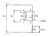
アルコールセンサ24は、呼気導入管20内を流れる気体中に含まれるエタノールガスを検出するセンサであり、例えば、金属酸化物半導体を用いたTGS2620(フィガロ技研社製、商品名)を使用することができ、図3に示すような回路で構成されている。アルコールセンサ24では、ヒーター電圧VHと回路電圧VCが印加され、センサ抵抗RSに直列に接続された負荷抵抗RLの両端電圧VOUTを、検出信号として出力する。従って、アルコールセンサ24は、呼気導入管20内を流れる気体中に含まれるエタノールガスの濃度が高くなるに従って、レベルが高い検出信号を出力し、呼気導入管20内を流れる気体中に含まれるエタノールガスの濃度が低くなるに従って、レベルが低い検出信号を出力する。
The
また、アルコールセンサ24は、ガス成分の選択性が比較的低く、エタノールガス以外に、例えば、水素、一酸化炭素、メタン、イソブタンなどに感度を有し、各々のガス成分に対して異なる感度特性を有している。
Further, the
この実施の形態によれば、吸い込みファン22を駆動することにより、ドライバから吐き出された呼気は呼気導入管20の吸い込み口20Aから呼気導入管20内に吸入されると共に、呼気が空気と混合されることで任意に希釈され、アルコールセンサ24へ一定流速で到達する。そして、呼気は、アルコールセンサ24に接触した後、呼気導入管20の外に排出される。
According to this embodiment, when the
アルコールセンサ24に感度を有するガス成分がアルコールセンサ24に接触することにより、アルコールセンサ24によって気体中のガス成分の濃度に応じた検出信号が出力される。アルコールセンサ24から出力された検出信号は、後述するエタノール濃度判定器に入力され、入力された検出信号に基づいて、検出対象のガス成分としてのエタノールガス成分の濃度が検出される。
When a gas component having sensitivity to the
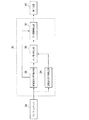
図4に示すように、エタノール濃度検出装置10は、アルコールセンサ24に接続され、かつ、エタノールガス成分の濃度を検出して、表示装置40に表示させるエタノール濃度判定器30を備えている。
As shown in FIG. 4, the ethanol
エタノール濃度判定器30は、アルコールセンサ24からの検出信号に基づいて、ガス吸着時の検出信号の変化特性を算出する吸着変化特性算出部32と、アルコールセンサ24からの検出信号に基づいて、ガス脱着時の検出信号の変化特性を算出する脱着変化特性算出部34と、算出されたガス吸着時の検出信号の変化特性とガス脱着時の検出信号の変化特性との比が所定範囲内であるか否かにより、呼気導入管20内を流れる気体中にエタノールガス成分が含まれているか否かを判定するガス成分判定部36と、呼気導入管20内を流れる気体中にエタノールガス成分が含まれている場合に、ガス吸着時の検出信号の変化特性に基づいて、呼気導入管20内を流れる気体中のエタノールガスの濃度を算出するガス濃度算出部38とを備えている。
The
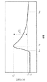
吸着変化特性算出部32は、呼気が導入され、導入された呼気に対する応答として、アルコールセンサ24からの検出信号が変化することを検知すると、所定の計測期間Tmsの検出信号の変化から、ガス吸着時の検出信号の変化特性として、検出信号の変化開始から検出信号がピークとなるまでの時間(図5のTth1−p参照)を算出すると共に、検出信号がピークとなるように変化しているときの検出信号の変化パターンを抽出する。
When the adsorption change
上記の検出信号の変化開始から検出信号がピークとなるまでの時間は以下のように算出される。検出信号の時系列変化から、検出信号の値が閾値Cth(例えば、ベース値+0.2V)を超えたときを、検出信号の変化開始時間tth1として検出し、検出信号がピークとなるときを、ピーク最大値時間tpとして検出する。そして、以下の(1)式に従って、検出信号の変化開始から検出信号がピークとなるまでの時間Tth1−pを算出する。
変化開始からピークとなるまでの時間Tth1−p=
ピーク最大値時間tp − 変化開始時間tth1 ・・・(1)
The time from the start of change of the detection signal to the peak of the detection signal is calculated as follows. When the value of the detection signal exceeds a threshold C th (for example, base value + 0.2V) from the time series change of the detection signal is detected as the detection signal change start time t th1 , and the detection signal reaches a peak Is detected as the peak maximum time tp. Then, according to the following equation (1), a time T th1-p from the start of change of the detection signal to the peak of the detection signal is calculated.
Time from start of change to peak T th1-p =
Peak maximum value time t p -change start time t th1 (1)
脱着変化特性算出部34は、アルコールセンサ24からの検出信号が変化することを検知すると、所定の計測期間Tmsの検出信号の変化から、ガス脱着時の検出信号の変化特性として、検出信号がピークとなってから検出信号の変化終了までの時間(図5のTp−th2参照)を算出する。
When the desorption change
上記の検出信号がピークとなってから検出信号の変化終了までの時間は以下のように算出される。検出信号の時系列変化から、検出信号がピークとなるときを、ピーク最大値時間tpとして検出し、検出信号の値が閾値Cthまで低下したときを、検出信号の変化終了時間tth2として検出する。そして、以下の(2)式に従って、検出信号がピークとなってから検出信号の変化終了までの時間Tp−th2を算出する。
ピークから変化終了までの時間Tp−th2=
変化終了時間tth2 − ピーク最大値時間tp ・・・(2)
The time from when the detection signal reaches a peak until the end of the change in the detection signal is calculated as follows. From the time series change of detection signals, when the detection signal reaches a peak, is detected as the peak maximum time t p, when the value of the detection signal is lowered to the threshold value C th, as a change end time of the detection signal t th2 To detect. Then, according to the following equation (2), a time T p-th2 from the peak of the detection signal to the end of the change of the detection signal is calculated.
Time from peak to end of change T p−th2 =
Change the end time t th2 - the peak maximum time t p ··· (2)
ここで、本実施の形態の原理について説明する。人の呼気のように、持続時間の短い(数秒以内)一過性のガスを対象としたガス測定において、酸化物半導体センサのように比較的選択性が低いセンサを用いて、ガス成分の濃度を検出する場合には、ガス成分によるセンサの応答に違いが生じにくいため、検出対象のガス成分でないガス成分によるセンサ応答に基づいて、検出対象のガス成分の濃度を誤って検出してしまう恐れがある。 Here, the principle of the present embodiment will be described. When measuring a gas with a short duration (within a few seconds), such as human exhalation, using a sensor with relatively low selectivity, such as an oxide semiconductor sensor, the concentration of gas components Since the difference in the sensor response due to the gas component is unlikely to be detected, the concentration of the gas component to be detected may be erroneously detected based on the sensor response due to the gas component that is not the gas component to be detected. There is.
また、一つのガスセンサからの検出信号の変化パターンの特徴のうち、変化開始からピークまでの検出信号の変化特性、すなわちガス吸着時の変化特性は、ガス成分の吸着特性のみならず、ガス拡散、反応の特性を反映するため、ガス成分の種類による違いが生じにくい。一方、ピークから変化終了までの検出信号の変化特性、すなわちガス脱着時の変化特性は、主にガス成分の脱着特性を反映しており、一定流速下における一過性のガスに対する検出信号の変化特性であっても、ガス成分の種類による違いが生じやすい。 Among the characteristics of the change pattern of the detection signal from one gas sensor, the change characteristic of the detection signal from the start of change to the peak, that is, the change characteristic at the time of gas adsorption is not only the adsorption characteristic of gas components, but also gas diffusion, Since the characteristics of the reaction are reflected, differences due to the types of gas components hardly occur. On the other hand, the change characteristic of the detection signal from the peak to the end of the change, that is, the change characteristic at the time of gas desorption mainly reflects the desorption characteristic of the gas component, and the change of the detection signal for the transient gas at a constant flow rate Even if it is a characteristic, the difference by the kind of gas component tends to arise.
このため、ガスセンサからの検出信号のガス吸着時の変化特性に対するガス脱着時の変化特性を指標化することにより、ガス濃度などの条件にかかわらず、目的のガス成分が存在するか否かを判定することができる。 For this reason, it is determined whether the target gas component exists regardless of the gas concentration and other conditions by indexing the change characteristic at the time of gas desorption relative to the change characteristic at the time of gas adsorption of the detection signal from the gas sensor. can do.
そこで、本実施の形態では、ガス成分判定部36において、算出された検出信号の変化開始からピークとなるまでの時間と、検出信号のピークから変化終了までの時間との比が、以下の(3)式で表される条件を満たす場合には、呼気導入管20内を流れる気体中にエタノールガス成分が含まれていると判定する。一方、以下の(3)式で表される条件を満たさない場合には、呼気導入管20内を流れる気体中にエタノールガス成分が含まれていないと判定する。
A1 < Tth1−p/Tp−th2 < A2 ・・・(3)
Therefore, in the present embodiment, in the gas
A 1 <T th1-p / T p-th2 <A 2 ··· (3)
なお、閾値A1には、例えば、1.5〜2の範囲の値を設定しておくのが好ましく、本実施の形態では、閾値A1として、1.7が設定されている。また、閾値A2は、例えば、2〜2.5の範囲の値を設定しておくのが好ましく、本実施の形態では、閾値A2として、2.3が設定されている。 Incidentally, the threshold value A 1 may, for example, is preferably setting the value in the range of 1.5 to 2, in this embodiment, as the threshold A 1, 1.7 is set. Further, the threshold A 2 is preferably set to a value in the range of 2 to 2.5, for example, and in the present embodiment, 2.3 is set as the threshold A 2 .
ガス濃度算出部38は、呼気導入管20内を流れる気体中にエタノールガス成分が含まれていると判定された場合に、呼気導入管20内を流れる気体中に含まれるエタノールガス成分の濃度を算出する。
The gas
ここで、エタノールガス成分の濃度を算出する原理について説明する。本実施の形態で用いるアルコールセンサは、アルコール成分の濃度を、センサ表面の酸素とアルコールが反応することにより変化するセンサ抵抗の抵抗値として捉えているという特徴がある。このことから、センサからの出力値は、アルコールと酸素との反応速度に比例すると考えられる。そのため、酸化物半導体センサの過度応答のモデル化は、アルコールと酸素との反応速度の時間変化をモデル化することにより実現することができる。 Here, the principle of calculating the concentration of the ethanol gas component will be described. The alcohol sensor used in the present embodiment is characterized in that the concentration of the alcohol component is regarded as the resistance value of the sensor resistance that changes when oxygen on the sensor surface reacts with the alcohol. From this, it is considered that the output value from the sensor is proportional to the reaction rate between alcohol and oxygen. Therefore, modeling of the excessive response of the oxide semiconductor sensor can be realized by modeling the time change of the reaction rate between alcohol and oxygen.
反応速度に関しては、ミカエリス・メンテン式を用いることにより、平衡状態における濃度との関係をモデル化できることがよく知られている。このモデル化の方法によれば、反応速度vが、以下の(4)式で表される。 Regarding the reaction rate, it is well known that the relationship with the concentration in the equilibrium state can be modeled by using the Michaelis-Menten equation. According to this modeling method, the reaction rate v is expressed by the following equation (4).

ただし、[S]はアルコール濃度を表わし、Vmax、Kmは、反応によって決まるパラメータである。 However, [S] represents the alcohol concentration, and V max and K m are parameters determined by the reaction.
上記(4)で表わされるモデルは、平衡状態におけるモデルであることから、過渡応答での反応速度を上手くモデル化できていない。そこで、ミカエリス・メンテン式を基に、以下のような仮定をおくことにより、過渡期の反応速度をモデル化する。
1.センサ周辺のアルコール濃度の変化に比べ、十分速く平衡状態に達する。つまり反応速度の変化は、センサ周辺の濃度変化にのみによって引き起こされる。
2.センサ周辺のアルコール濃度の変化は、装置入り口を一定濃度とした場合、以下の(5)式で表される一次元拡散方程式に従う。
Since the model represented by the above (4) is a model in an equilibrium state, the reaction rate in the transient response cannot be well modeled. Therefore, based on the Michaelis-Menten equation, the following reaction rate is modeled by making the following assumptions.
1. Compared to the change in alcohol concentration around the sensor, the equilibrium state is reached sufficiently quickly. That is, the change in the reaction rate is caused only by the concentration change around the sensor.
2. The change in the alcohol concentration around the sensor follows a one-dimensional diffusion equation expressed by the following equation (5) when the concentration at the entrance of the apparatus is constant.
ただし、λ1は拡散係数、xは装置入り口からの距離、tは時間、C1は入り口濃度、erfcは相補誤差関数である。
3.センサの反応遅れは、以下の(6)式で表されるn次遅れ式により表現できる。
Where λ 1 is the diffusion coefficient, x is the distance from the entrance of the apparatus, t is the time, C 1 is the entrance concentration, and erfc is the complementary error function.
3. The response delay of the sensor can be expressed by an nth-order lag equation expressed by the following equation (6).
ただし、λ2は、時定数である。 Where λ 2 is a time constant.
上記1.〜3.の仮定に基づいてセンサ値の時間変化をモデル化すると、以下の(7)式で表わすことができる。 Above 1. ~ 3. When the change in the sensor value over time is modeled on the basis of the above assumption, it can be expressed by the following equation (7).
上記の相補誤差関数を計算するためには、繰り返し計算が必要である。そのため、ここでは、非常に簡単な近似として以下の(8)式を用いて濃度の推定を行う。 In order to calculate the above complementary error function, iterative calculation is required. Therefore, here, the concentration is estimated using the following equation (8) as a very simple approximation.
ただし、a、b、cは、システム同定から得られるパラメータとする。また、上記(8)式を用いることにより、システム同定にかかる時間と、使用するメモリ容量とを低減することができる。 However, a, b, and c are parameters obtained from system identification. Further, by using the above equation (8), the time required for system identification and the memory capacity to be used can be reduced.
ガス濃度算出部38は、抽出された検出信号がピークとなるように変化しているときの検出信号の変化パターンを用いて、システム同定を行う。そして、ガス濃度算出部38は、システム同定から得られるパラメータを用いて、上記(8)式に従って、呼気導入管20内を流れる気体中に含まれるエタノール成分と同じ濃度のエタノール成分が持続して含まれる場合にアルコールセンサ24から出力される検出信号の飽和出力値を予測する。
The gas
そして、ガス濃度算出部38は、アルコールセンサ24からの検出信号の値とエタノールガス濃度との予め求められた関係(対数関数)に基づいて、予測された検出信号の飽和出力値に対応するエタノールガス成分の濃度を、呼気導入管20内を流れる気体中に含まれるエタノール成分の濃度として算出する。
The gas
次に、第1の実施の形態に係るエタノール濃度検出装置10の作用について説明する。ドライバが車両シートに着座すると、ドライバの呼気が呼気導入管20に吹き込まれる状態となり、ドライバによってイグニッションスイッチがオンされると、エタノール濃度検出装置10のエタノール濃度判定器30において、図6に示すエタノール濃度検出処理ルーチンが実行される。
Next, the operation of the ethanol
まず、ステップ100において、アルコールセンサ24からの検出信号の変化から、呼気導入管20に含まれる気体中のガス成分の変化が検知されたか否かを判定し、所定量以上の検出信号の変化量が検知されると、呼気が呼気導入管20内に導入されてガス成分に変化が生じたと判断し、ステップ102へ進む。
First, in
ステップ102では、アルコールセンサ24から、所定の計測期間Tms分の検出信号を取得する。そして、ステップ104において、上記ステップ102で取得した所定の計測期間Tms分の検出信号から、ガス吸着時の検出信号の変化特性として、検出信号の変化開始から検出信号がピークとなるまでの時間を算出すると共に、検出信号がピークとなるように変化しているときの検出信号の変化パターンを抽出する。
In
次のステップ106では、上記ステップ102で取得した所定の計測期間Tms分の検出信号から、ガス脱着時の検出信号の変化特性として、検出信号がピークとなってから検出信号の変化終了までの時間を算出する。
In the
そして、ステップ108において、上記(3)式に従って、上記ステップ104で算出された検出信号の変化開始からピークとなるまでの時間と、上記ステップ106で算出された検出信号がピークとなってから変化終了までの時間との比が、所定範囲内であるか否かを判定する。上記の時間の比が、所定範囲内でないと判定された場合には、呼気導入管20内を流れる気体中にエタノールガス成分が含まれていないと判断し、上記ステップ100へ戻る。
Then, in
上記ステップ108において、上記の時間の比が、所定範囲内であると判定された場合には、呼気導入管20内を流れる気体中にエタノールガス成分が含まれていると判断し、ステップ110へ移行する。
If it is determined in
ステップ110では、上記ステップ102で抽出された、検出信号がピークとなるように変化しているときの検出信号の変化パターンを用いて、システム同定を行い、上記(8)式に従って、呼気導入管20内を流れる気体中のエタノール成分と同じ濃度のエタノール成分が持続して含まれる場合にアルコールセンサ24から出力される検出信号の飽和出力値を予測する。
In
次のステップ112において、上記ステップ110で予測された検出信号の飽和出力値に基づいて、呼気導入管20内を流れる気体中に含まれるエタノール成分の濃度を算出し、ステップ114において、上記ステップ112で算出されたエタノールガス成分の濃度を表示装置40に表示させて、エタノール濃度検出処理ルーチンを終了する。
In the
以上説明したように、第1の実施の形態に係るエタノール濃度検出装置によれば、アルコールセンサの検出信号の変化開始からピークまでの時間と、ピークから変化終了までの時間との比に基づいて、検出対象の気体中にエタノールガス成分が含まれると判定された場合に、エタノールガス成分の濃度を検出することにより、呼気のような持続時間の短いガスを検出対象とする場合であっても、簡易な処理で、エタノールガス成分の濃度を精度よく検出することができる。 As described above, according to the ethanol concentration detection apparatus according to the first embodiment, based on the ratio of the time from the start of change of the detection signal of the alcohol sensor to the peak and the time from the peak to the end of change. Even when it is determined that an ethanol gas component is contained in the gas to be detected, by detecting the concentration of the ethanol gas component, a gas having a short duration such as exhalation is to be detected. The concentration of the ethanol gas component can be accurately detected by simple processing.
また、人の呼気のように、持続時間の短い一過性のガスを対象としたガス測定において、酸化物半導体センサのように比較的選択性が低いセンサを用いてガス成分の濃度を検出する場合であっても、ガス成分によるセンサ応答に違いを判別し、目的成分であるエタノールガス成分が存在するか否かを判別することができる。この結果、目的成分であるエタノール成分のみを選択的に定量することができ、他のガス成分による誤検出を防止することができる。 Further, in gas measurement for a transient gas having a short duration such as human exhalation, the concentration of the gas component is detected by using a sensor having relatively low selectivity such as an oxide semiconductor sensor. Even in this case, it is possible to determine the difference in the sensor response due to the gas component and to determine whether or not the ethanol gas component as the target component exists. As a result, only the ethanol component that is the target component can be selectively quantified, and erroneous detection due to other gas components can be prevented.
また、運転者の呼気のように持続時間の短い一過性のガスの中の目的成分(例えばエタノールガス成分)の濃度を、他のガス成分、例えば食品に含まれるガス成分等と区別して測定することができるため、運転者の呼気に含まれるエタノールガス成分の濃度を精度よく検出することができ、運転者の飲酒を精度よく検出することができる。 In addition, the concentration of the target component (for example, ethanol gas component) in a transient gas with a short duration such as the exhalation of the driver is distinguished from other gas components, for example, gas components contained in food. Therefore, the concentration of the ethanol gas component contained in the driver's breath can be detected with high accuracy, and the driver's drinking can be detected with high accuracy.
なお、上記の実施の形態では、検出信号の変化開始時間を検出するための閾値と同じ閾値を用いて、検出信号の変化終了時間を検出する場合を例に説明したが、これに限定されるものではなく、検出信号の変化開始時間を検出するための閾値とは異なる閾値(例えば、ベース値+0.5V)を用いて、検出信号の値がこの閾値まで低下したときを、検出信号の変化終了時間として検出するようにしてもよい。 In the above embodiment, the case where the change end time of the detection signal is detected using the same threshold as the threshold for detecting the change start time of the detection signal has been described as an example. However, the present invention is not limited to this. Instead of a threshold for detecting the change start time of the detection signal (for example, base value + 0.5V), when the value of the detection signal drops to this threshold, the change in the detection signal You may make it detect as end time.
次に、第2の実施の形態に係るエタノール濃度検出装置について説明する。なお、第2の実施の形態に係るエタノール濃度検出装置は、第1の実施の形態と同様の構成となっているため、同一符号を付して説明を省略する。 Next, an ethanol concentration detection apparatus according to the second embodiment will be described. In addition, since the ethanol concentration detection apparatus according to the second embodiment has the same configuration as that of the first embodiment, the same reference numerals are given and description thereof is omitted.
第2の実施の形態では、ガス吸着時の検出信号の変化特性として、検出信号のピークの高さを算出している点が、第1の実施の形態と主に異なっている。 The second embodiment is mainly different from the first embodiment in that the peak height of the detection signal is calculated as the change characteristic of the detection signal during gas adsorption.
第2の実施の形態に係るエタノール濃度検出装置のエタノール濃度判定器30では、吸着変化特性算出部32によって、所定の計測期間Tmsの検出信号の変化から、ガス吸着時の検出信号の変化特性として、検出信号のピークの高さ(図7のΔCp参照)を算出すると共に、検出信号がピークとなるように変化しているときの検出信号の変化パターンを抽出する。
In the ethanol
上記の検出信号のピークの高さは以下のように算出される。検出信号の時系列変化から、変化前の検出信号の値を、検出信号のベース値Cbとして検出すると共に、検出信号がピークとなったときのピーク最大値Cpを検出する。そして、以下の(9)式に従って、検出信号のピークの高さΔCpを算出する。
検出信号のピークの高さΔCp=
ピーク最大値Cp − ベース値Cb ・・・(9)
ガス成分判定部36は、算出された検出信号のピークの高さと、検出信号のピークから変化終了までの時間との比が、以下の(10)式で表される条件を満たす場合には、呼気導入管20内を流れる気体中にエタノールガス成分が含まれていると判定する。一方、以下の(10)式で表される条件を満たさない場合には、呼気導入管20内を流れる気体中にエタノールガス成分が含まれていないと判定する。
B1 < LN(Tp−th2/ΔCp) < B2 ・・・(10)
The peak height of the detection signal is calculated as follows. From the time series change of detection signals, the previous value of the detection signal change, and detects as the base value C b of the detection signal, the detection signal to detect a peak maximum C p when peaked. Then, the peak height ΔC p of the detection signal is calculated according to the following equation (9).
Peak height ΔC p of detection signal =
Peak maximum value C p -base value C b (9)
When the ratio between the calculated peak height of the detection signal and the time from the peak of the detection signal to the end of the change satisfies the condition expressed by the following equation (10), the gas
B 1 <LN (T p−th 2 / ΔC p ) <B 2 (10)
ただし、LN()は自然対数を表わす。また、上記(10)式は、以下の(10)´式に書き換えることもできる。
B1 < LN(Tp−th2)−LN(ΔCp) < B2 ・・・(10)´
However, LN () represents a natural logarithm. Further, the above expression (10) can be rewritten as the following expression (10) ′.
B 1 <LN (T p- th2) -LN (ΔC p) <
なお、閾値B1には、例えば、2〜2.7の範囲の値を設定しておくのが好ましく、本実施の形態では、閾値B1として、2.3が設定されている。また、閾値B2には、例えば、2.7〜3.3の範囲の値を設定しておくのが好ましく、本実施の形態では、閾値B2として、3.0が設定されている。 Incidentally, the threshold value B 1 represents, for example, is preferably setting the value in the range of 2 to 2.7, in this embodiment, as the threshold B 1, 2.3 is set. Further, the threshold value B 2, for example, is preferably setting the value in the range of 2.7 to 3.3, in this embodiment, as the threshold value B 2, 3.0 is set.
上記(10)式又は(10)´式の代わりに、以下の(10)´´式を使用することも可能である。
B1 < Tp−th2/ΔCp < B2 ・・・(10)´´
It is also possible to use the following expression (10) ″ instead of the above expression (10) or expression (10) ′.
B 1 <T p-th2 / ΔC p <
上記(10)´´式を用いる場合には、閾値B1には、例えば、7〜15の範囲の値を設定しておくのが好ましく、本実施の形態では、閾値B1として、10を設定しておけばよい。また、閾値B2には、例えば、15〜25の範囲の値を設定しておくのが好ましく、本実施の形態では、閾値B2として、20を設定しておけばよい。 In the case of using the above (10)'' expression threshold B 1 represents, for example, it is preferably setting the value in the range of 7 to 15, in this embodiment, as the threshold B 1, a 10 Just set it up. Further, the threshold value B 2, for example, preferably in setting the value in the range of 15 to 25, in this embodiment, as the threshold value B 2, may be set to 20.
なお、第2の実施の形態に係るエタノール濃度検出装置の他の構成及び作用については、第1の実施の形態と同様であるため、説明を省略する。 In addition, about the other structure and effect | action of the ethanol concentration detection apparatus which concern on 2nd Embodiment, since it is the same as that of 1st Embodiment, description is abbreviate | omitted.
以上説明したように、第2の実施の形態に係るエタノール濃度検出装置によれば、アルコールセンサの検出信号のピークの高さと、ピークから変化終了までの時間との比に基づいて、検出対象の気体中にエタノールガス成分が含まれると判定された場合に、エタノールガス成分の濃度を検出することにより、呼気のような持続時間の短いガスを検出対象とする場合であっても、簡易な処理で、エタノールガス成分の濃度を精度よく検出することができる。 As described above, according to the ethanol concentration detection apparatus according to the second embodiment, the detection target is detected based on the ratio between the peak height of the detection signal of the alcohol sensor and the time from the peak to the end of the change. When it is determined that an ethanol gas component is contained in the gas, simple processing is possible even when a gas having a short duration, such as exhalation, is detected by detecting the concentration of the ethanol gas component. Thus, the concentration of the ethanol gas component can be accurately detected.
次に、第3の実施の形態に係るエタノール濃度検出装置について説明する。なお、第3の実施の形態に係るエタノール濃度検出装置の構成は、第1の実施の形態と同様の構成となっているため、同一符号を付して説明を省略する。 Next, an ethanol concentration detection apparatus according to a third embodiment will be described. In addition, since the structure of the ethanol concentration detection apparatus which concerns on 3rd Embodiment is the structure similar to 1st Embodiment, it attaches | subjects the same code | symbol and abbreviate | omits description.
第3の実施の形態では、ガス吸着時の検出信号の変化特性として、検出信号の変化率の最大値を算出している点と、ガス脱着時の検出信号の変化特性として、検出信号の変化率の最小値を算出している点とが、第1の実施の形態と主に異なっている。 In the third embodiment, the maximum value of the change rate of the detection signal is calculated as the change characteristic of the detection signal at the time of gas adsorption, and the change of the detection signal as the change characteristic of the detection signal at the time of gas desorption. The difference from the first embodiment is that the minimum value of the rate is calculated.
第3の実施の形態に係るエタノール濃度検出装置のエタノール濃度判定器30では、吸着変化特性算出部32によって、所定の計測期間Tmsの検出信号の変化から、ガス吸着時の検出信号の変化特性として、検出信号の変化率(変化の傾き)の最大値(図8のα1参照)を算出すると共に、検出信号がピークとなるように変化しているときの検出信号の変化パターンを抽出する。
In the ethanol
上記の検出信号の変化率の最大値の算出では、まず、検出信号の時系列変化から、検出信号の変化率の時系列変化を算出し、算出された変化率の時系列変化から、検出信号の変化率の最大値α1を検出する。 In calculating the maximum value of the change rate of the detection signal, first, the time series change of the change rate of the detection signal is calculated from the time series change of the detection signal, and the detection signal is calculated from the time series change of the calculated change rate. The maximum value α 1 of the rate of change of the above is detected.
また、脱着変化特性算出部34によって、所定の計測期間Tmsの検出信号の変化から、ガス脱着時の検出信号の変化特性として、検出信号の変化率の最小値(図8のα2参照)を算出する。上記の検出信号の変化率の最小値の算出では、まず、検出信号の時系列変化から、検出信号の変化率の時系列変化を算出し、算出された変化率の時系列変化から、検出信号の変化率の最小値α2(α2<0)を検出する。
Further, the desorption change
ガス成分判定部36は、算出された検出信号の変化率の最小値と、検出信号の変化率の最大値との比が、以下の(11)式で表される条件を満たす場合には、呼気導入管20内を流れる気体中にエタノールガス成分が含まれていると判定する。一方、以下の(11)式で表される条件を満たさない場合には、呼気導入管20内を流れる気体中にエタノールガス成分が含まれていないと判定する。
D1 < −(α2/α1) < D2 ・・・(11)
When the ratio between the calculated minimum value of the change rate of the detection signal and the maximum value of the change rate of the detection signal satisfies the condition expressed by the following equation (11), the gas component determination unit 36: It is determined that the ethanol gas component is contained in the gas flowing in the
D 1 <-(α 2 / α 1 ) <D 2 (11)
なお、閾値D1には、例えば、0.2〜0.5の範囲の値を設定しておくのが好ましく、本実施の形態では、閾値D1として、0.3が設定されている。また、閾値D2には、例えば、0.5〜0.8の範囲の値を設定しておくのが好ましく、本実施の形態では、閾値D2として、0.7が設定されている。 Incidentally, the threshold value D 1 is, for example, is preferably setting the value in the range of 0.2 to 0.5, in this embodiment, as the threshold D 1, 0.3 is set. Further, the threshold value D 2 are, for example, is preferably setting the value in the range of 0.5 to 0.8, in this embodiment, as the threshold value D 2, 0.7 is set.
なお、第3の実施の形態に係るエタノール濃度検出装置の他の構成及び作用については、第1の実施の形態と同様であるため、説明を省略する。 In addition, about the other structure and effect | action of the ethanol concentration detection apparatus which concern on 3rd Embodiment, since it is the same as that of 1st Embodiment, description is abbreviate | omitted.
以上説明したように、第3の実施の形態に係るエタノール濃度検出装置によれば、アルコールセンサの検出信号の変化率の最大値と最小値との比に基づいて、検出対象の気体中にエタノールガス成分が含まれると判定された場合に、エタノールガス成分の濃度を検出することにより、呼気のような持続時間の短いガスを検出対象とする場合であっても、簡易な処理で、エタノールガス成分の濃度を精度よく検出することができる。 As described above, according to the ethanol concentration detection apparatus according to the third embodiment, ethanol is detected in the detection target gas based on the ratio between the maximum value and the minimum value of the change rate of the detection signal of the alcohol sensor. When it is determined that a gas component is contained, the concentration of the ethanol gas component is detected. The concentration of the component can be detected with high accuracy.
次に、第4の実施の形態に係るエタノール濃度検出装置について説明する。なお、第4の実施の形態に係るエタノール濃度検出装置の構成は、第1の実施の形態と同様の構成となっているため、同一符号を付して説明を省略する。 Next, an ethanol concentration detection apparatus according to a fourth embodiment will be described. In addition, since the structure of the ethanol concentration detection apparatus which concerns on 4th Embodiment is the structure similar to 1st Embodiment, it attaches | subjects the same code | symbol and abbreviate | omits description.
第4の実施の形態では、ガス吸着時の検出信号の変化特性として、検出信号がピークとなるように変化しているときの変化パターンを抽出している点と、ガス脱着時の検出信号の変化特性として、検出信号がピークとなった以降の変化パターンを抽出している点と、各変化パターンから予測される検出信号の飽和出力値に基づいて、エタノールガス成分が含まれるか否かを判定している点とが、第1の実施の形態と主に異なっている。 In the fourth embodiment, as a change characteristic of the detection signal at the time of gas adsorption, a change pattern when the detection signal changes so as to reach a peak is extracted, and a detection signal at the time of gas desorption is extracted. As a change characteristic, whether or not the ethanol gas component is included is determined based on the point of extracting the change pattern after the detection signal reaches its peak and the saturated output value of the detection signal predicted from each change pattern. The point of determination is mainly different from the first embodiment.
第4の実施の形態に係るエタノール濃度検出装置のエタノール濃度判定器30では、吸着変化特性算出部32によって、所定の計測期間Tmsの検出信号の変化から、ガス吸着時の検出信号の変化特性として、検出信号がピークとなるように変化しているときの検出信号の変化パターンを抽出する。
In the ethanol
また、脱着変化特性算出部34によって、所定の計測期間Tmsの検出信号の変化から、ガス脱着時の検出信号の変化特性として、検出信号がピークとなった以降の検出信号の変化パターンを抽出する。
Further, the change pattern of the detection signal after the peak of the detection signal is extracted as the change characteristic of the detection signal at the time of gas desorption from the change of the detection signal in the predetermined measurement period Tms by the desorption change
ガス成分判定部36は、以下に説明するように、呼気導入管20内を流れる気体中にエタノールガス成分が含まれているか否かを判定する。
The gas
まず、抽出された、検出信号がピークとなるように変化しているときの検出信号の変化パターンに基づいて、システム同定を行う。そして、システム同定から得られるパラメータを用いて、上記(8)式に従って、呼気導入管20内を流れる気体中に含まれるエタノール成分と同じ濃度のエタノール成分が持続して含まれる場合にアルコールセンサ24から出力される検出信号の飽和出力値(図9のC1参照)を予測する。
First, system identification is performed based on the extracted change pattern of the detection signal when the detection signal changes so as to reach a peak. Then, using the parameter obtained from the system identification, the
また、抽出された、検出信号がピークとなった以降の検出信号の変化パターン(脱着特性の変化パターン)に基づいて、呼気導入管20内を流れる気体中に含まれるエタノール成分と同じ濃度のエタノール成分が持続して含まれる場合にアルコールセンサ24から出力される検出信号の飽和出力値(図9のC2参照)を予測する。
Further, based on the extracted detection signal change pattern (desorption characteristic change pattern) after the detection signal has reached its peak, ethanol having the same concentration as the ethanol component contained in the gas flowing in the
ここで、脱着特性の変化パターンから飽和出力値を予測する原理について説明する。 Here, the principle of predicting the saturation output value from the change pattern of the desorption characteristics will be described.
ミカエリス・メンテン式を基に、過渡応答と同様な仮定を置くことにより、以下のように、アルコールセンサ24の減衰応答のモデル化を行う。
Based on the Michaelis-Menten equation, the attenuation response of the
濃度が減少し始める時刻をt0とすると、センサ位置xにおける脱着時の濃度変化C(x、t)は、以下の(12)式、(13)式で表される。 Assuming that the time when the concentration starts to decrease is t 0 , the concentration change C (x, t) at the time of desorption at the sensor position x is expressed by the following equations (12) and (13).
計算量を低減させるために近似解を用いると、上記(13)式は、以下の(14)式で表される。 When an approximate solution is used to reduce the amount of calculation, the above equation (13) is expressed by the following equation (14).
上記(4)式に上記(14)式を代入し、反応遅れは、上記(8)式と同様に3次遅れ項まで用いることにより、センサの出力値f(t)は、以下の(15)式で表される。 By substituting the above equation (14) into the above equation (4) and using the reaction delay up to the third-order lag term as in the above equation (8), the output value f (t) of the sensor becomes the following (15 ) Expression.
ただし、a、b、c、d、t0は、センサについてシステム同定して求められたパラメータである。 However, a, b, c, d , t 0 is a parameter determined by system identification for the sensor.
ガス成分判定部36は、呼気導入管20内を流れる気体中に含まれるエタノール成分と同じ濃度のエタノール成分が持続して含まれる場合にアルコールセンサ24から出力される検出信号の飽和出力値を、上記(15)式に従って予測する。
The gas
そして、ピーク以降の検出信号の変化パターンから予測された検出信号の飽和出力値C2と、ピークとなるように変化している検出信号の変化パターンから予測された検出信号の飽和出力値C1との比が、以下の(16)式で表される条件を満たす場合には、呼気導入管20内を流れる気体中にエタノールガス成分が含まれていると判定する。一方、以下の(16)式で表される条件を満たさない場合には、呼気導入管20内を流れる気体中にエタノールガス成分が含まれていないと判定する。
F1 < C2/C1 < F2 ・・・(16)
Then, a saturated output value C 2 of the predicted detection signal from the change pattern of the detection signal after the peak, the saturated output value C 1 of the predicted detection signal from the change pattern of the detection signal is changed so that the peak If the ratio satisfies the condition expressed by the following equation (16), it is determined that the ethanol gas component is contained in the gas flowing in the
F 1 <C 2 / C 1 <F 2 (16)
なお、閾値F1には、例えば、0.8〜1の範囲の値を設定しておくのが好ましく、本実施の形態では、閾値F1として、0.9が設定されている。また、閾値F2には、例えば、1〜1.2の範囲の値を設定しておくのが好ましく、本実施の形態では、閾値F2として、1.1が設定されている。 Incidentally, the threshold F 1, for example, is preferably setting the value in the range of 0.8 to 1, in this embodiment, as the threshold F 1, 0.9 is set. Further, the threshold F 2, for example, is preferably setting the value in the range of 1-1.2, in the present embodiment, as the threshold F 2, 1.1 is set.
ガス濃度算出部38は、ガス成分判定部36でピークとなるように変化している検出信号の変化パターンから予測された検出信号の飽和出力値を用いて、呼気導入管20内を流れる気体中に含まれるエタノールガス成分の濃度を算出する。
The gas
なお、第4の実施の形態に係るエタノール濃度検出装置の他の構成及び作用については、第1の実施の形態と同様であるため、説明を省略する。 In addition, about the other structure and effect | action of the ethanol concentration detection apparatus which concern on 4th Embodiment, since it is the same as that of 1st Embodiment, description is abbreviate | omitted.
以上説明したように、第4の実施の形態に係るエタノール濃度検出装置によれば、アルコールセンサの検出信号のピークまでの変化パターンから予測される検出信号の飽和出力値と、ピーク以降の変化パターンから予測される検出信号の飽和出力値との比に基づいて、検出対象の気体中にエタノールガス成分が含まれると判定された場合に、エタノールガス成分の濃度を検出することにより、呼気のような持続時間の短いガスを検出対象とする場合であっても、簡易な処理で、エタノールガス成分の濃度を精度よく検出することができる。 As described above, according to the ethanol concentration detection apparatus of the fourth embodiment, the saturated output value of the detection signal predicted from the change pattern up to the peak of the detection signal of the alcohol sensor and the change pattern after the peak If it is determined that the gas to be detected contains an ethanol gas component based on the ratio of the detected signal to the saturation output value of the detection signal, the concentration of the ethanol gas component is detected. Even when a gas with a short duration is used as a detection target, the concentration of the ethanol gas component can be accurately detected with a simple process.
なお、上記の実施の形態では、ピークとなるように変化している検出信号の変化パターンから予測された検出信号の飽和出力値を用いて、エタノールガス成分の濃度を算出する場合を例に説明したが、これに限定されるものではなく、ピークとなった以降の検出信号の変化パターンから予測された検出信号の飽和出力値を用いて、エタノールガス成分の濃度を算出するようにしてもよい。 In the above embodiment, the case where the concentration of the ethanol gas component is calculated using the saturated output value of the detection signal predicted from the change pattern of the detection signal that changes so as to reach a peak will be described as an example. However, the present invention is not limited to this, and the concentration of the ethanol gas component may be calculated using the saturated output value of the detection signal predicted from the change pattern of the detection signal after the peak. .
次に、第5の実施の形態に係るエタノール濃度検出装置について説明する。なお、第1の実施の形態と同様の構成となっている部分については同一符号を付して説明を省略する。 Next, an ethanol concentration detection apparatus according to a fifth embodiment will be described. In addition, about the part which has the structure similar to 1st Embodiment, the same code | symbol is attached | subjected and description is abbreviate | omitted.
第5の実施の形態では、アルコールセンサと、多くの種類のガス成分に感度を有するガスセンサとを用いている点が、第1の実施の形態と主に異なっている。 The fifth embodiment is mainly different from the first embodiment in that an alcohol sensor and a gas sensor having sensitivity to many types of gas components are used.
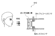
図10に示すように、第5の実施の形態に係るエタノール濃度検出装置510では、呼気導入管20の中間部の内部に、アルコールセンサ24と、多くの種類のガス成分に感度を有するガスセンサ524とが取り付けられている。アルコールセンサ24と、ガスセンサ524とは、呼気導入管20の中間部の内部に対向するように取り付けられている。
As shown in FIG. 10, in the ethanol
ガスセンサ524は、目的成分(エタノール)以外のガス成分に対する感度(変化特性)が、アルコールセンサ24と異なり、多くの種類のガス成分に感度を有している。ガスセンサ524としては、例えば、空気質センサ(空気の汚れを検知するセンサ)を用いることができ、TGS2600(フィガロ技研社製、商品名)を使用することができる。
Unlike the
ガスセンサ524は、呼気導入管20内を流れる気体中に含まれる、感度を有するガス成分の濃度が高くなるに従って、レベルが高い検出信号を出力し、呼気導入管20内を流れる気体中に含まれる、感度を有するガス成分の濃度が低くなるに従って、レベルが低い検出信号を出力する。
The
この実施の形態によれば、吸い込みファン22を駆動することにより、ドライバから吐き出された呼気は呼気導入管20の吸い込み口20Aから呼気導入管20内に吸入されると共に、呼気が空気と混合されることで任意に希釈され、アルコールセンサ24及びガスセンサ524へ一定流速で到達する。そして、呼気は、アルコールセンサ24及びガスセンサ524に接触した後、呼気導入管20から外部に排出される。
According to this embodiment, when the
アルコールセンサ24及びガスセンサ524の各々から出力された検出信号は、後述するエタノール濃度判定器530に入力され、入力された検出信号に基づいて、検出対象ガスとしてのエタノールガスの濃度が検出される。
Detection signals output from each of the
図11に示すように、エタノール濃度判定器530は、脱着変化特性算出部34と、ガスセンサ524からの検出信号に基づいて、ガス脱着時の検出信号の変化特性を算出する脱着変化特性算出部534と、アルコールセンサ24及びガスセンサ524の各々からの検出信号に基づいて算出されたガス脱着時の検出信号の変化特性の比が、所定範囲内であるか否かにより、呼気導入管20内を流れる気体中にエタノールガス成分が含まれているか否かを判定するガス成分判定部536と、アルコールセンサ24からの検出信号に基づいて、ガス吸着時の検出信号の変化パターンを抽出する吸着変化抽出部537と、ガス濃度算出部38とを備えている。
As shown in FIG. 11, the ethanol
脱着変化特性算出部534は、所定の計測期間Tmsのガスセンサ524からの検出信号の変化から、ガス脱着時のガスセンサ524の検出信号の変化特性として、以下の(17)式に従って、検出信号がピークとなってから検出信号の変化終了までの時間T2p−th2を算出する。
ピークから変化終了までの時間T2p−th2=
変化終了時間t2th2 − ピーク最大値時間t2p ・・・(17)
ここで、本実施の形態の原理について説明する。上述したように、ピークから変化終了までの検出信号の変化特性、すなわちガス脱着時の変化特性は、主にガス成分の脱着特性を反映しており、一定流速下における一過性のガスに対する検出信号の変化特性であっても、ガス成分の種類による違いが生じやすい。このため、複数種類のガスセンサからの検出信号のガス脱着時の変化特性を比較して、ガス脱着時の変化特性を指標化することにより、ガス濃度などの条件にかかわらず、目的のガス成分が存在するか否かを判定することができる。
The desorption change
Time from peak to end of change T2 p-th2 =
Change end time t2 th2 -peak maximum time t2 p (17)
Here, the principle of the present embodiment will be described. As described above, the change characteristic of the detection signal from the peak to the end of the change, that is, the change characteristic at the time of gas desorption mainly reflects the desorption characteristic of the gas component, and detection for a transient gas at a constant flow rate. Even the change characteristics of the signal tend to vary depending on the type of gas component. For this reason, by comparing the change characteristics at the time of gas desorption of detection signals from multiple types of gas sensors, and by indexing the change characteristics at the time of gas desorption, the target gas component can be detected regardless of conditions such as gas concentration. It can be determined whether or not it exists.
そこで、本実施の形態では、ガス成分判定部536において、算出されたアルコールセンサ24の検出信号の変化開始からピークとなるまでの時間Tp−th2と、ガスセンサ524の検出信号のピークから変化終了までの時間T2p−th2との比が、以下の(18)式で表される条件を満たす場合には、呼気導入管20内を流れる気体中にエタノールガス成分が含まれていると判定する。一方、以下の(18)式で表される条件を満たさない場合には、呼気導入管20内を流れる気体中にエタノールガス成分が含まれていないと判定する。
G1 < Tp−th2/T2p−th2 < G2 ・・・(18)
Therefore, in the present embodiment, in the gas
G 1 <T p-th2 / T2 p-th2 <
なお、閾値G1には、例えば、0.8〜1の範囲の値を設定しておくのが好ましく、本実施の形態では、閾値G1として、0.9が設定されている。また、閾値G2には、例えば、1〜1.2の範囲の値を設定しておくのが好ましく、本実施の形態では、閾値G2として、1.1が設定されている。 Incidentally, the threshold value G 1 is preferably, for example, the previously set value in the range of 0.8 to 1, in this embodiment, as the threshold G 1, 0.9 is set. Further, the threshold value G 2 is, for example, is preferably setting the value in the range of 1-1.2, in the present embodiment, as the threshold value G 2, 1.1 is set.
吸着変化抽出部537は、所定の計測期間Tmsのアルコールセンサ24の検出信号の変化から、ガス吸着時の変化特性として、検出信号がピークとなるように変化しているときの検出信号の変化パターンを抽出する。
The adsorption
ガス濃度算出部38は、呼気導入管20内を流れる気体中にエタノールガス成分が含まれていると判定された場合に、抽出された、アルコールセンサ24の検出信号がピークとなるように変化しているときの検出信号の変化パターンを用いて、呼気導入管20内を流れる気体中に含まれるエタノールガス成分の濃度を算出する。
When it is determined that the ethanol gas component is contained in the gas flowing through the
次に第5の実施の形態に係るエタノール濃度検出処理ルーチンについて、図12を用いて説明する。なお、第1の実施の形態と同様の処理については同一符号を付して説明を省略する。 Next, an ethanol concentration detection processing routine according to the fifth embodiment will be described with reference to FIG. Note that the same processes as those of the first embodiment are denoted by the same reference numerals, and description thereof is omitted.
まず、ステップ100において、アルコールセンサ24からの検出信号の変化から、呼気導入管20に含まれる気体中のガス成分の変化が検知されたか否かを判定し、所定量以上の検出信号の変化量が検知されると、ステップ550へ進む。
First, in
ステップ550では、アルコールセンサ24及びガスセンサ524の各々から、所定の計測期間Tms分の検出信号を取得する。そして、ステップ552において、上記ステップ550でアルコールセンサ24から取得した所定の計測期間Tms分の検出信号から、アルコールセンサ24のガス脱着時の検出信号の変化特性として、検出信号がピークとなってから検出信号の変化終了までの時間を算出する。
In
次のステップ554では、上記ステップ550でガスセンサ524から取得した所定の計測期間Tms分の検出信号から、ガスセンサ524のガス脱着時の検出信号の変化特性として、検出信号がピークとなってから検出信号の変化終了までの時間を算出する。
In the
そして、ステップ556において、上記(18)式に従って、上記ステップ552で算出されたアルコールセンサ24の検出信号がピークとなってから変化終了までの時間と、上記ステップ554で算出された検出信号がピークとなってから変化終了までの時間との比が、所定範囲内であるか否かを判定する。上記の時間の比が、所定範囲内でないと判定された場合には、呼気導入管20内を流れる気体中にエタノールガス成分が含まれていないと判断し、上記ステップ100へ戻る。
In
上記ステップ556において、上記の時間の比が、所定範囲内であると判定された場合には、呼気導入管20内を流れる気体中にエタノールガス成分が含まれていると判断し、ステップ558へ移行する。
If it is determined in
ステップ558では、上記ステップ550でアルコールセンサ24から取得した所定の計測期間Tms分の検出信号から、検出信号がピークとなるように変化しているときの検出信号の変化パターンを抽出する。
In
ステップ110では、上記ステップ558で抽出された検出信号がピークとなるように変化しているときの検出信号の変化パターンを用いてシステム同定を行い、上記(8)式に従って、アルコールセンサ24からの検出信号の飽和出力値を予測する。
In
次のステップ112において、上記ステップ110で予測された検出信号の飽和出力値に基づいて、呼気導入管20内を流れる気体中に含まれるエタノール成分の濃度を算出し、ステップ114において、上記ステップ112で算出されたエタノールガス成分の濃度を表示装置40に表示させて、エタノール濃度検出処理ルーチンを終了する。
In the
以上説明したように、第5の実施の形態に係るエタノール濃度検出装置によれば、アルコールセンサの検出信号がピークになってから変化終了するまでの時間と、ガスセンサの検出信号がピークになってから変化終了するまでの時間との比に基づいて、検出対象の気体中にエタノールガス成分が含まれると判定された場合に、エタノールガス成分の濃度を検出することにより、呼気のような持続時間の短いガスを検出対象とする場合であっても、簡易な処理で、エタノールガス成分の濃度を精度よく検出することができる。 As described above, according to the ethanol concentration detection apparatus according to the fifth embodiment, the time from when the detection signal of the alcohol sensor reaches the peak until the end of the change and the detection signal of the gas sensor reach the peak. Based on the ratio from the time until the end of the change to the end of the change, it is determined that the ethanol gas component is contained in the gas to be detected. Even when a short gas is used as a detection target, the concentration of the ethanol gas component can be accurately detected by a simple process.
なお、上記の実施の形態では、アルコールセンサ及びガスセンサの各々の検出信号について、ピークになってから変化終了するまでの時間を算出した場合を例に説明したが、これに限定されるものではなく、例えば、ガス脱着時の検出信号の変化特性として、上記第3の実施の形態と同様に、アルコールセンサ及びガスセンサの各々の検出信号について、検出信号の変化率の最小値を算出するようにしてもよい。 In the above-described embodiment, the case where the time from the peak to the end of the change has been described as an example for each detection signal of the alcohol sensor and the gas sensor. However, the present invention is not limited to this. For example, as the change characteristic of the detection signal at the time of gas desorption, the minimum value of the change rate of the detection signal is calculated for each detection signal of the alcohol sensor and the gas sensor, as in the third embodiment. Also good.
次に、第6の実施の形態に係るエタノール濃度検出装置について説明する。なお、第6の実施の形態に係るエタノール濃度検出装置の構成は、第5の実施の形態と同様の構成となっているため、同一符号を付して説明を省略する。 Next, an ethanol concentration detection apparatus according to a sixth embodiment will be described. In addition, since the structure of the ethanol concentration detection apparatus which concerns on 6th Embodiment is the structure similar to 5th Embodiment, it attaches | subjects the same code | symbol and abbreviate | omits description.
第6の実施の形態では、アルコールセンサのガス脱着時の検出信号の変化特性として、アルコールセンサの検出信号がピークとなった以降の変化パターンを抽出している点と、ガスセンサのガス脱着時の検出信号の変化特性として、ガスセンサの検出信号がピークとなった以降の変化パターンを抽出している点と、各センサの変化パターンから予測される検出信号の飽和出力値に基づいて、エタノールガス成分が含まれるか否かを判定している点とが、第5の実施の形態と主に異なっている。 In the sixth embodiment, as a change characteristic of the detection signal at the time of gas desorption of the alcohol sensor, a change pattern after the detection signal of the alcohol sensor reaches a peak is extracted, and at the time of gas desorption of the gas sensor. Based on the detection signal change characteristics, the change pattern after the detection signal of the gas sensor has peaked, and the saturation output value of the detection signal predicted from the change pattern of each sensor. Is different from the fifth embodiment mainly in that it is determined whether or not is included.
第6の実施の形態に係るエタノール濃度検出装置のエタノール濃度判定器530では、脱着変化特性算出部34によって、アルコールセンサ24の所定の計測期間Tmsの検出信号の変化から、ガス脱着時の検出信号の変化特性として、アルコールセンサ24の検出信号がピークとなった以降の検出信号の変化パターンを抽出する。また、脱着変化特性算出部534によって、ガスセンサ524の所定の計測期間Tmsの検出信号の変化から、ガス脱着時の検出信号の変化特性として、ガスセンサ524の検出信号がピークとなった以降の検出信号の変化パターンを抽出する。
In the ethanol
ガス成分判定部536は、以下に説明するように、呼気導入管20内を流れる気体中にエタノールガス成分が含まれているか否かを判定する。
The gas
まず、抽出された、アルコールセンサ24の検出信号がピークとなった以降の検出信号の変化パターンに基づいて、上記第1の実施の形態と同様に、呼気導入管20内を流れる気体中に含まれるエタノール成分と同じ濃度のエタノール成分が持続して含まれる場合にアルコールセンサ24から出力される検出信号の飽和出力値を予測する。
First, based on the extracted change pattern of the detection signal after the detection signal of the
また、抽出された、ガスセンサ524の検出信号がピークとなった以降の検出信号の変化パターンに基づいて、呼気導入管20内を流れる気体中に含まれるガス成分と同じ濃度のガス成分が持続して含まれる場合にガスセンサ524から出力される検出信号の飽和出力値を予測する。
Moreover, based on the extracted change pattern of the detection signal after the detection signal of the
なお、アルコールセンサ24の場合と同様に、ガスセンサ524の検出信号のピーク以降の検出信号の変化パターン(脱着特性の変化パターン)から、上記(15)式に従って、出力される検出信号の飽和出力値を予測すればよい。上記(15)式のパラメータa、b、c、d、t0は、アルコールセンサ24に関するパラメータと異なっている。
As in the case of the
そして、アルコールセンサ24のピーク以降の検出信号の変化パターンから予測されたアルコールセンサ24の検出信号の飽和出力値C2と、ガスセンサ524のピーク以降の検出信号の変化パターンから予測されたガスセンサ524の検出信号の飽和出力値E2との比が、以下の(19)式で表される条件を満たす場合には、呼気導入管20内を流れる気体中にエタノールガス成分が含まれていると判定する。一方、以下の(19)式で表される条件を満たさない場合には、呼気導入管20内を流れる気体中にエタノールガス成分が含まれていないと判定する。
H1 < C2/E2 < H2 ・・・(19)
The
H 1 <C 2 / E 2 <H 2 (19)
なお、閾値H1,H2には、実験的又は統計的に予め求められた判別閾値を設定しておけばよい。 Incidentally, the threshold H 1, H 2, it is sufficient to set the experimental or statistically obtained in advance determination threshold value.
ガス濃度算出部38は、ガス成分判定部536においてアルコールセンサ24のピークとなった以降の検出信号の変化パターンから予測された検出信号の飽和出力値を用いて、エタノールガス成分の濃度を算出する。
The gas
なお、第6の実施の形態に係るエタノール濃度検出装置の他の構成及び作用については、第5の実施の形態と同様であるため、説明を省略する。 In addition, about the other structure and effect | action of the ethanol concentration detection apparatus which concern on 6th Embodiment, since it is the same as that of 5th Embodiment, description is abbreviate | omitted.
以上説明したように、第6の実施の形態に係るエタノール濃度検出装置によれば、アルコールセンサの検出信号がピークとなった以降の変化パターンから予測される検出信号の飽和出力値と、ガスセンサの検出信号がピークとなった以降の変化パターンから予測される検出信号の飽和出力値との比に基づいて、検出対象の気体中にエタノールガス成分が含まれると判定された場合に、エタノールガス成分の濃度を検出することにより、呼気のような持続時間の短いガスを検出対象とする場合であっても、簡易な処理で、エタノールガス成分の濃度を精度よく検出することができる。 As described above, according to the ethanol concentration detection apparatus according to the sixth embodiment, the saturated output value of the detection signal predicted from the change pattern after the detection signal of the alcohol sensor reaches the peak, and the gas sensor When it is determined that the gas to be detected contains an ethanol gas component based on the ratio to the saturated output value of the detection signal predicted from the change pattern after the detection signal reaches its peak, the ethanol gas component By detecting the concentration of ethanol, the concentration of the ethanol gas component can be accurately detected with a simple process even when a gas having a short duration, such as exhalation, is targeted for detection.
なお、上記の第5の実施の形態及び第6の実施の形態では、アルコールセンサと空気質センサなどのガスセンサとを用いた場合を例に説明したが、これに限定されるものではなく、アルコールセンサと共に、ガス成分に対する感度がアルコールセンサと異なるガスセンサを用いて構成すればよい。例えば、アルコールセンサと共に、酸素センサや、水蒸気センサ、二酸化炭素センサを用いて構成することができる。酸素センサとしては、固体電解質を用いて酸素濃度を検出する酸素センサを用いることができ、水蒸気センサとしては、酸化物半導体または高分子膜静電容量を用いて水蒸気の濃度を検出する水蒸気センサを用いることができる。また、二酸化炭素センサとしては、固体電解質を用いて二酸化炭素の濃度を検出する二酸化炭素センサを用いることができる。 In the fifth embodiment and the sixth embodiment described above, the case where the alcohol sensor and the gas sensor such as the air quality sensor are used has been described as an example. However, the present invention is not limited to this. What is necessary is just to comprise using the gas sensor in which the sensitivity with respect to a gas component differs from an alcohol sensor with a sensor. For example, an oxygen sensor, a water vapor sensor, or a carbon dioxide sensor can be used together with an alcohol sensor. As the oxygen sensor, an oxygen sensor that detects the oxygen concentration using a solid electrolyte can be used. As the water vapor sensor, a water vapor sensor that detects the concentration of water vapor using an oxide semiconductor or polymer film capacitance Can be used. Moreover, as a carbon dioxide sensor, the carbon dioxide sensor which detects the density | concentration of a carbon dioxide using a solid electrolyte can be used.
また、上記の第1の実施の形態、第2の実施の形態、及び第5の実施の形態において、検出信号の値が閾値以下まで低下した時間を、検出信号の変化終了の時間として検出する場合を例に説明したが、これに限定されるものではなく、検出信号の値が、ピーク最大値に対して一定割合となる値(例えば、ピーク最大値の30%)まで低下した時間を、検出信号の変化終了の時間として検出するようにしてもよい。 Further, in the first embodiment, the second embodiment, and the fifth embodiment described above, the time when the value of the detection signal has decreased to a threshold value or less is detected as the time when the detection signal change ends. Although the case has been described as an example, the present invention is not limited to this, and the time when the value of the detection signal has decreased to a value that is a constant ratio to the peak maximum value (for example, 30% of the peak maximum value) You may make it detect as the time of the end of a change of a detection signal.
また、上記の第1の実施の形態〜第6の実施の形態では、アルコールセンサの検出信号の変化パターンから予測される検出信号の飽和出力値を用いて、エタノールガス成分の濃度を算出する場合を例に説明したが、これに限定されるものではなく、アルコールセンサの検出信号のベース値及びピーク値から、検出信号の飽和出力値を予測し、予測された検出信号の飽和出力値を用いて、エタノールガス成分の濃度を算出するようにしてもよい。 In the first to sixth embodiments, the concentration of the ethanol gas component is calculated using the saturated output value of the detection signal predicted from the change pattern of the detection signal of the alcohol sensor. However, the present invention is not limited to this, and the saturated output value of the detection signal is predicted from the base value and the peak value of the detection signal of the alcohol sensor, and the predicted saturated output value of the detection signal is used. Thus, the concentration of the ethanol gas component may be calculated.
また、センサ出力(V)を用いて、エタノールガス成分が含まれるか否かを判定する場合を例に説明したが、これに限定されるものではなく、センサ出力から計算される濃度計算値(ppm又はmg/L)を用いて、エタノールガス成分が含まれるか否かを判定するようにしてもよい。この場合には、上記の各実施の形態で例示した、範囲を規定する判定閾値として、異なった値を設定しておけばよい。 Moreover, although the case where it was determined as an example whether the ethanol gas component is contained using sensor output (V) was demonstrated, it is not limited to this, The concentration calculation value ( ppm or mg / L) may be used to determine whether an ethanol gas component is included. In this case, different values may be set as the determination threshold value for defining the range exemplified in each of the above embodiments.
また、上記の実施の形態では、算出されたエタノールガス成分の濃度を表示する場合を例に説明したが、これに限定されるものではなく、例えば、算出したエタノールガス成分の濃度と予め定めた閾値とを比較し、算出したエタノールガス成分の濃度が閾値以上の場合にエタノールの濃度が高いと判定し、エンジンが始動できないようにする等の不正ができないように制御するようにしてもよい。 In the above embodiment, the case where the calculated concentration of the ethanol gas component is displayed has been described as an example. However, the present invention is not limited to this. For example, the calculated concentration of the ethanol gas component is predetermined. Control may be performed so as to prevent fraud such as preventing the engine from starting by comparing the threshold value and determining that the ethanol concentration is high when the calculated ethanol gas component concentration is equal to or greater than the threshold value.
上記では、ドライバの呼気からエタノールガス成分の濃度を検出する例について説明したが、エタノール濃度検出装置を携帯可能に構成する等により、本発明はドライバ以外の人間の呼気からエタノールガス成分の濃度を検出する場合にも適用できるものである。 In the above, the example of detecting the concentration of the ethanol gas component from the exhalation of the driver has been described, but by configuring the ethanol concentration detection device to be portable, the present invention can reduce the concentration of the ethanol gas component from the exhalation of humans other than the driver. The present invention can also be applied to detection.
10、510 エタノール濃度検出装置
24 アルコールセンサ
30、530 エタノール濃度判定器
32 吸着変化特性算出部
34、534 脱着変化特性算出部
36、536 ガス成分判定部
38 ガス濃度算出部
524 ガスセンサ
DESCRIPTION OF
Claims (9)
前記ガスセンサより出力された前記検出信号に基づいて、前記検出信号がピークとなった以降の前記検出信号の変化特性を含む複数種類の変化特性を算出する変化特性算出手段と、
前記変化特性算出手段によって算出された前記複数種類の変化特性に基づいて、前記検出対象の気体中に検出対象のガス成分が含まれるか否かを判定する判定手段と、
前記判定手段によって前記検出対象の気体中に前記検出対象のガス成分が含まれると判定された場合に、前記ガスセンサより出力された前記検出信号に基づいて、前記検出対象の気体中に含まれる前記検出対象のガス成分の濃度を検出するガス濃度検出手段と、
を含むガス検出装置。 A gas sensor that outputs a detection signal whose level increases as the concentration of the gas component contained in the gas to be detected increases and decreases as the concentration of the gas component decreases;
Based on the detection signal output from the gas sensor, change characteristic calculation means for calculating a plurality of types of change characteristics including the change characteristic of the detection signal after the detection signal has reached a peak;
Determining means for determining whether or not a gas component to be detected is contained in the gas to be detected based on the plurality of types of change characteristics calculated by the change characteristic calculating means;
When it is determined by the determination means that the gas component to be detected is contained in the gas to be detected, the gas contained in the gas to be detected is based on the detection signal output from the gas sensor. Gas concentration detection means for detecting the concentration of the gas component to be detected;
A gas detection device.
一方の前記ガスセンサより出力された前記検出信号に基づいて、前記検出信号がピークとなった以降の前記検出信号の変化特性を算出する第1変化特性算出手段と、
他方の前記ガスセンサより出力された前記検出信号に基づいて、前記検出信号がピークとなった以降の前記検出信号の変化特性を算出する第2変化特性算出手段と、
前記第1変化特性算出手段によって算出された前記変化特性と前記第2変化特性算出手段によって算出された前記変化特性とを比較して、前記検出対象の気体中に検出対象のガス成分が含まれるか否かを判定する判定手段と、
前記判定手段によって前記検出対象の気体中に前記検出対象のガス成分が含まれると判定された場合に、前記ガスセンサより出力された前記検出信号に基づいて、前記検出対象の気体中に含まれる前記検出対象のガス成分の濃度を検出するガス濃度検出手段と、
を含むガス検出装置。 A detection signal is output that has different sensitivities to the gas components, increases in level as the concentration of the gas component contained in the gas to be detected increases, and decreases as the concentration of the gas component decreases. Two gas sensors,
First change characteristic calculation means for calculating a change characteristic of the detection signal after the detection signal has reached a peak based on the detection signal output from one of the gas sensors;
Second change characteristic calculating means for calculating a change characteristic of the detection signal after the detection signal reaches a peak based on the detection signal output from the other gas sensor;
The change characteristic calculated by the first change characteristic calculation means and the change characteristic calculated by the second change characteristic calculation means are compared, and the detection target gas component is included in the detection target gas. Determination means for determining whether or not,
When it is determined by the determination means that the gas component to be detected is contained in the gas to be detected, the gas contained in the gas to be detected is based on the detection signal output from the gas sensor. Gas concentration detection means for detecting the concentration of the gas component to be detected;
A gas detection device.
前記判定手段は、前記第1変化パターンに基づいて、前記検出対象の気体中にガス成分が持続して含まれる場合に前記ガスセンサから出力される前記検出信号を予測すると共に、前記第2変化パターンに基づいて、前記検出対象の気体中にガス成分が持続して含まれる場合に前記ガスセンサから出力される前記検出信号を予測する予測手段を備え、前記予測手段によって予測された前記検出信号に基づいて、前記検出対象の気体中に前記検出対象のガス成分が含まれるか否かを判定する請求項1記載のガス検出装置。 The change characteristic calculation means includes a first change pattern of the detection signal when the detection signal changes to be a peak as the plurality of types of change characteristics, and after the detection signal has reached a peak. Calculating a second change pattern of the detection signal;
The determination means predicts the detection signal output from the gas sensor when a gas component is continuously included in the gas to be detected based on the first change pattern, and the second change pattern. Based on the detection signal predicted by the prediction means, the prediction means predicting the detection signal output from the gas sensor when a gas component is continuously contained in the gas to be detected The gas detection device according to claim 1, wherein it is determined whether or not the detection target gas component is contained in the detection target gas.
前記判定手段は、前記第1変化特性算出手段によって算出された前記変化パターンに基づいて、前記検出対象の気体中にガス成分が持続して含まれる場合に前記一方のガスセンサから出力される前記検出信号を予測すると共に、前記第2変化特性算出手段によって算出された前記変化パターンに基づいて、前記検出対象の気体中にガス成分が持続して含まれる場合に前記他方のガスセンサから出力される前記検出信号を予測する予測手段を備え、前記予測手段によって予測された前記検出信号の各々を比較して、前記検出対象の気体中に前記検出対象のガス成分が含まれるか否かを判定する請求項7記載のガス検出装置。 The change characteristic of the detection signal is a change pattern of the detection signal after the detection signal reaches a peak,
The determination means outputs the detection output from the one gas sensor when a gas component is continuously contained in the gas to be detected based on the change pattern calculated by the first change characteristic calculation means. The signal output from the other gas sensor when predicting a signal and based on the change pattern calculated by the second change characteristic calculating means when a gas component is continuously included in the gas to be detected. A prediction unit that predicts a detection signal is provided, and each of the detection signals predicted by the prediction unit is compared to determine whether or not the detection target gas component is contained in the detection target gas. Item 8. The gas detection device according to Item 7.
Priority Applications (1)
| Application Number | Priority Date | Filing Date | Title |
|---|---|---|---|
| JP2008164803A JP4989567B2 (en) | 2008-06-24 | 2008-06-24 | Gas detector |
Applications Claiming Priority (1)
| Application Number | Priority Date | Filing Date | Title |
|---|---|---|---|
| JP2008164803A JP4989567B2 (en) | 2008-06-24 | 2008-06-24 | Gas detector |
Publications (2)
| Publication Number | Publication Date |
|---|---|
| JP2010008097A true JP2010008097A (en) | 2010-01-14 |
| JP4989567B2 JP4989567B2 (en) | 2012-08-01 |
Family
ID=41588799
Family Applications (1)
| Application Number | Title | Priority Date | Filing Date |
|---|---|---|---|
| JP2008164803A Expired - Fee Related JP4989567B2 (en) | 2008-06-24 | 2008-06-24 | Gas detector |
Country Status (1)
| Country | Link |
|---|---|
| JP (1) | JP4989567B2 (en) |
Cited By (2)
| Publication number | Priority date | Publication date | Assignee | Title |
|---|---|---|---|---|
| JP2010223587A (en) * | 2009-03-19 | 2010-10-07 | Toyota Central R&D Labs Inc | Gas detection device |
| US10627448B2 (en) | 2015-11-30 | 2020-04-21 | Lg Chem, Ltd. | Apparatus and method for detecting battery cell failure due to unknown discharge current |
Citations (7)
| Publication number | Priority date | Publication date | Assignee | Title |
|---|---|---|---|---|
| JPS63121742A (en) * | 1986-11-11 | 1988-05-25 | Figaro Eng Inc | Detection of carbon monoxide |
| JPH06242039A (en) * | 1993-02-16 | 1994-09-02 | Nok Corp | Gas identifying system |
| JPH07311170A (en) * | 1994-05-16 | 1995-11-28 | Figaro Eng Inc | Method and apparatus for detecting gas |
| JP2001337061A (en) * | 2000-05-25 | 2001-12-07 | Figaro Eng Inc | Method for detecting anomaly in gas sensor and its device |
| WO2008081757A1 (en) * | 2006-12-28 | 2008-07-10 | Kabushiki Kaisha Toyota Chuo Kenkyusho | Gas detecting method and gas detecting apparatus |
| JP2009042166A (en) * | 2007-08-10 | 2009-02-26 | Toyota Central R&D Labs Inc | Gas detector |
| JP4477780B2 (en) * | 1999-04-27 | 2010-06-09 | エフアイエス株式会社 | Exhaled gas detection method and apparatus |
-
2008
- 2008-06-24 JP JP2008164803A patent/JP4989567B2/en not_active Expired - Fee Related
Patent Citations (7)
| Publication number | Priority date | Publication date | Assignee | Title |
|---|---|---|---|---|
| JPS63121742A (en) * | 1986-11-11 | 1988-05-25 | Figaro Eng Inc | Detection of carbon monoxide |
| JPH06242039A (en) * | 1993-02-16 | 1994-09-02 | Nok Corp | Gas identifying system |
| JPH07311170A (en) * | 1994-05-16 | 1995-11-28 | Figaro Eng Inc | Method and apparatus for detecting gas |
| JP4477780B2 (en) * | 1999-04-27 | 2010-06-09 | エフアイエス株式会社 | Exhaled gas detection method and apparatus |
| JP2001337061A (en) * | 2000-05-25 | 2001-12-07 | Figaro Eng Inc | Method for detecting anomaly in gas sensor and its device |
| WO2008081757A1 (en) * | 2006-12-28 | 2008-07-10 | Kabushiki Kaisha Toyota Chuo Kenkyusho | Gas detecting method and gas detecting apparatus |
| JP2009042166A (en) * | 2007-08-10 | 2009-02-26 | Toyota Central R&D Labs Inc | Gas detector |
Cited By (2)
| Publication number | Priority date | Publication date | Assignee | Title |
|---|---|---|---|---|
| JP2010223587A (en) * | 2009-03-19 | 2010-10-07 | Toyota Central R&D Labs Inc | Gas detection device |
| US10627448B2 (en) | 2015-11-30 | 2020-04-21 | Lg Chem, Ltd. | Apparatus and method for detecting battery cell failure due to unknown discharge current |
Also Published As
| Publication number | Publication date |
|---|---|
| JP4989567B2 (en) | 2012-08-01 |
Similar Documents
| Publication | Publication Date | Title |
|---|---|---|
| CN104237456B (en) | Utilize the measurement of concetration of mobile device | |
| JP2011122996A5 (en) | ||
| KR101621774B1 (en) | Alcohol Analyzing Method, Recording Medium and Apparatus For Using the Same | |
| EP1806276A3 (en) | Diving information processing device, and related control method, control program and program storage device | |
| JP2011050731A5 (en) | ||
| US9901288B2 (en) | Methods of detecting gaseous component levels in a breath | |
| WO2007100965A3 (en) | METHOD OF COHb CALCULATION IN A CARBON MONOXIDE DETECTOR | |
| US20210018479A1 (en) | Odor sensing apparatus, odor detection method, and computer-readable recording medium | |
| US20120253691A1 (en) | Testing a humidity sensor | |
| JP4989567B2 (en) | Gas detector | |
| JP2021107829A5 (en) | ||
| US9329161B2 (en) | Monitoring of the functionality of a converter of a breath analysis apparatus | |
| AU634943B2 (en) | Method and system for detecting underground mine fires | |
| JP2021107829A (en) | Biogas detection device, method and program | |
| KR102534577B1 (en) | Gas analysis system and gas analysis method | |
| JP4901401B2 (en) | Alcohol detection device and alcohol detection method | |
| US20230286466A1 (en) | Method and system for determination and classification of intoxicating substance in a breath sample facilitated by a user interaction scheme | |
| MX2021008203A (en) | Breath alcohol content device security and sensing. | |
| JP4967920B2 (en) | Gas detector | |
| WO2021154147A1 (en) | Method and system for tracer-aided determination and classification of intoxicating substance in breath sample | |
| JP2010121946A (en) | Gas detector | |
| JP2010281698A (en) | Skin gas detection device | |
| JP2011027464A (en) | Gas detector | |
| JP3717074B2 (en) | Information processing apparatus and method | |
| US20160022172A1 (en) | Systems and methods for fluid testing |
Legal Events
| Date | Code | Title | Description |
|---|---|---|---|
| A621 | Written request for application examination |
Free format text: JAPANESE INTERMEDIATE CODE: A621 Effective date: 20110202 |
|
| A977 | Report on retrieval |
Free format text: JAPANESE INTERMEDIATE CODE: A971007 Effective date: 20120416 |
|
| TRDD | Decision of grant or rejection written | ||
| A01 | Written decision to grant a patent or to grant a registration (utility model) |
Free format text: JAPANESE INTERMEDIATE CODE: A01 Effective date: 20120424 |
|
| A01 | Written decision to grant a patent or to grant a registration (utility model) |
Free format text: JAPANESE INTERMEDIATE CODE: A01 |
|
| A61 | First payment of annual fees (during grant procedure) |
Free format text: JAPANESE INTERMEDIATE CODE: A61 Effective date: 20120427 |
|
| R150 | Certificate of patent or registration of utility model |
Free format text: JAPANESE INTERMEDIATE CODE: R150 Ref document number: 4989567 Country of ref document: JP Free format text: JAPANESE INTERMEDIATE CODE: R150 |
|
| FPAY | Renewal fee payment (event date is renewal date of database) |
Free format text: PAYMENT UNTIL: 20150511 Year of fee payment: 3 |
|
| R250 | Receipt of annual fees |
Free format text: JAPANESE INTERMEDIATE CODE: R250 |
|
| LAPS | Cancellation because of no payment of annual fees |