JP2010008028A - Molten metal production method using vertical melting furnace - Google Patents
Molten metal production method using vertical melting furnace Download PDFInfo
- Publication number
- JP2010008028A JP2010008028A JP2008171521A JP2008171521A JP2010008028A JP 2010008028 A JP2010008028 A JP 2010008028A JP 2008171521 A JP2008171521 A JP 2008171521A JP 2008171521 A JP2008171521 A JP 2008171521A JP 2010008028 A JP2010008028 A JP 2010008028A
- Authority
- JP
- Japan
- Prior art keywords
- oxygen
- furnace
- iron
- tuyere
- coke
- Prior art date
- Legal status (The legal status is an assumption and is not a legal conclusion. Google has not performed a legal analysis and makes no representation as to the accuracy of the status listed.)
- Granted
Links
- 238000002844 melting Methods 0.000 title claims abstract description 36
- 230000008018 melting Effects 0.000 title claims abstract description 36
- 239000002184 metal Substances 0.000 title claims abstract description 22
- 229910052751 metal Inorganic materials 0.000 title claims abstract description 22
- 238000004519 manufacturing process Methods 0.000 title claims description 14
- XEEYBQQBJWHFJM-UHFFFAOYSA-N Iron Chemical compound [Fe] XEEYBQQBJWHFJM-UHFFFAOYSA-N 0.000 claims abstract description 135
- 229910052760 oxygen Inorganic materials 0.000 claims abstract description 112
- 239000001301 oxygen Substances 0.000 claims abstract description 112
- QVGXLLKOCUKJST-UHFFFAOYSA-N atomic oxygen Chemical compound [O] QVGXLLKOCUKJST-UHFFFAOYSA-N 0.000 claims abstract description 111
- 229910052742 iron Inorganic materials 0.000 claims abstract description 68
- 238000002347 injection Methods 0.000 claims abstract description 38
- 239000007924 injection Substances 0.000 claims abstract description 38
- 239000000571 coke Substances 0.000 claims abstract description 36
- 238000002485 combustion reaction Methods 0.000 claims abstract description 9
- 238000007664 blowing Methods 0.000 claims abstract description 5
- 239000000428 dust Substances 0.000 claims description 45
- 239000010802 sludge Substances 0.000 claims description 25
- 239000007787 solid Substances 0.000 claims description 4
- 238000000034 method Methods 0.000 abstract description 16
- 239000000243 solution Substances 0.000 abstract 1
- 239000007789 gas Substances 0.000 description 15
- 239000002994 raw material Substances 0.000 description 15
- 239000000843 powder Substances 0.000 description 12
- XLYOFNOQVPJJNP-UHFFFAOYSA-N water Substances O XLYOFNOQVPJJNP-UHFFFAOYSA-N 0.000 description 12
- 238000000465 moulding Methods 0.000 description 11
- 239000011230 binding agent Substances 0.000 description 10
- 238000001723 curing Methods 0.000 description 9
- 239000000463 material Substances 0.000 description 9
- UQSXHKLRYXJYBZ-UHFFFAOYSA-N Iron oxide Chemical compound [Fe]=O UQSXHKLRYXJYBZ-UHFFFAOYSA-N 0.000 description 8
- OKTJSMMVPCPJKN-UHFFFAOYSA-N Carbon Chemical compound [C] OKTJSMMVPCPJKN-UHFFFAOYSA-N 0.000 description 7
- 230000008569 process Effects 0.000 description 7
- 238000009628 steelmaking Methods 0.000 description 5
- ODINCKMPIJJUCX-UHFFFAOYSA-N Calcium oxide Chemical compound [Ca]=O ODINCKMPIJJUCX-UHFFFAOYSA-N 0.000 description 4
- 239000003575 carbonaceous material Substances 0.000 description 4
- 238000006722 reduction reaction Methods 0.000 description 4
- 239000002893 slag Substances 0.000 description 4
- 238000012360 testing method Methods 0.000 description 4
- 239000004568 cement Substances 0.000 description 3
- 238000009826 distribution Methods 0.000 description 3
- 230000001965 increasing effect Effects 0.000 description 3
- 238000002156 mixing Methods 0.000 description 3
- 239000000203 mixture Substances 0.000 description 3
- 230000009467 reduction Effects 0.000 description 3
- RHZUVFJBSILHOK-UHFFFAOYSA-N anthracen-1-ylmethanolate Chemical compound C1=CC=C2C=C3C(C[O-])=CC=CC3=CC2=C1 RHZUVFJBSILHOK-UHFFFAOYSA-N 0.000 description 2
- 239000003830 anthracite Substances 0.000 description 2
- 235000012255 calcium oxide Nutrition 0.000 description 2
- 239000000292 calcium oxide Substances 0.000 description 2
- 229910052799 carbon Inorganic materials 0.000 description 2
- 239000003610 charcoal Substances 0.000 description 2
- 239000003245 coal Substances 0.000 description 2
- 238000000748 compression moulding Methods 0.000 description 2
- 238000005261 decarburization Methods 0.000 description 2
- 238000001125 extrusion Methods 0.000 description 2
- 239000008187 granular material Substances 0.000 description 2
- 239000002245 particle Substances 0.000 description 2
- 238000009423 ventilation Methods 0.000 description 2
- 229910018072 Al 2 O 3 Inorganic materials 0.000 description 1
- 239000004484 Briquette Substances 0.000 description 1
- 235000019738 Limestone Nutrition 0.000 description 1
- 229910000805 Pig iron Inorganic materials 0.000 description 1
- 239000011398 Portland cement Substances 0.000 description 1
- 229910004298 SiO 2 Inorganic materials 0.000 description 1
- 229910000831 Steel Inorganic materials 0.000 description 1
- 239000000654 additive Substances 0.000 description 1
- 230000000996 additive effect Effects 0.000 description 1
- PNEYBMLMFCGWSK-UHFFFAOYSA-N aluminium oxide Inorganic materials [O-2].[O-2].[O-2].[Al+3].[Al+3] PNEYBMLMFCGWSK-UHFFFAOYSA-N 0.000 description 1
- -1 and if necessary Substances 0.000 description 1
- 230000008901 benefit Effects 0.000 description 1
- 235000012216 bentonite Nutrition 0.000 description 1
- 239000011400 blast furnace cement Substances 0.000 description 1
- 230000008859 change Effects 0.000 description 1
- 150000001805 chlorine compounds Chemical class 0.000 description 1
- 239000000567 combustion gas Substances 0.000 description 1
- 150000001875 compounds Chemical class 0.000 description 1
- 239000000470 constituent Substances 0.000 description 1
- 238000011161 development Methods 0.000 description 1
- 238000004090 dissolution Methods 0.000 description 1
- 230000000694 effects Effects 0.000 description 1
- 230000002708 enhancing effect Effects 0.000 description 1
- 239000010881 fly ash Substances 0.000 description 1
- 238000000227 grinding Methods 0.000 description 1
- 230000020169 heat generation Effects 0.000 description 1
- 230000000887 hydrating effect Effects 0.000 description 1
- 239000012535 impurity Substances 0.000 description 1
- 238000011835 investigation Methods 0.000 description 1
- 150000002505 iron Chemical class 0.000 description 1
- 239000006028 limestone Substances 0.000 description 1
- CPLXHLVBOLITMK-UHFFFAOYSA-N magnesium oxide Inorganic materials [Mg]=O CPLXHLVBOLITMK-UHFFFAOYSA-N 0.000 description 1
- 238000005259 measurement Methods 0.000 description 1
- 239000003607 modifier Substances 0.000 description 1
- 150000002926 oxygen Chemical class 0.000 description 1
- 230000035699 permeability Effects 0.000 description 1
- 230000000630 rising effect Effects 0.000 description 1
- 238000005096 rolling process Methods 0.000 description 1
- 238000010079 rubber tapping Methods 0.000 description 1
- 239000010959 steel Substances 0.000 description 1
- 230000001629 suppression Effects 0.000 description 1
- 239000004094 surface-active agent Substances 0.000 description 1
Images


Classifications
-
- Y—GENERAL TAGGING OF NEW TECHNOLOGICAL DEVELOPMENTS; GENERAL TAGGING OF CROSS-SECTIONAL TECHNOLOGIES SPANNING OVER SEVERAL SECTIONS OF THE IPC; TECHNICAL SUBJECTS COVERED BY FORMER USPC CROSS-REFERENCE ART COLLECTIONS [XRACs] AND DIGESTS
- Y02—TECHNOLOGIES OR APPLICATIONS FOR MITIGATION OR ADAPTATION AGAINST CLIMATE CHANGE
- Y02P—CLIMATE CHANGE MITIGATION TECHNOLOGIES IN THE PRODUCTION OR PROCESSING OF GOODS
- Y02P10/00—Technologies related to metal processing
- Y02P10/20—Recycling
Landscapes
- Manufacture And Refinement Of Metals (AREA)
- Manufacture Of Iron (AREA)
- Vertical, Hearth, Or Arc Furnaces (AREA)
Abstract
Description
本発明は、竪型溶解炉を用い、コークスの燃焼熱により鉄系スクラップを溶解して溶銑を製造する方法に関する。 The present invention relates to a method for producing hot metal by melting iron-based scrap by the combustion heat of coke using a vertical melting furnace.
従来、竪型溶解炉を用いて鉄系スクラップを溶解するプロセスが知られており(例えば、特許文献1)、このプロセスでは、竪型溶解炉の炉頂部から鉄系スクラップとコークスを装入し、炉下部に設けられた複数の羽口(送風羽口)から熱風を吹き込み、コークスの燃焼熱で鉄系スクラップを溶解することにより溶銑が得られる。
上記のようなプロセスで溶銑を製造する場合に、生産量を増加させようとすると、次のような問題がある。すなわち、生産量を増加させる場合、排ガス量を増加させないために酸素富化を行うのが有効であるが、羽口から吹き込まれた酸素が炉中心部まで十分に届かない場合には、炉中心部側の領域でのガスの流れが少なくなる。その結果、炉中心部側でのコークスの燃焼や鉄系スクラップの溶解が不十分となり、出銑温度の低下を招くばかりでなく、場合によっては操業自体に支障をきたす恐れがある。また、ダストがうまく排出されずに炉内に蓄積し、ガスの通気性が低下する等の問題も生じる。さらに、多量の酸素富化の場合においては、羽口先の温度が非常に高温になるため、安定的な操業に支障をきたす可能性もある。 In the case of producing hot metal by the above process, there is the following problem when trying to increase the production amount. That is, when increasing the production volume, it is effective to perform oxygen enrichment in order not to increase the amount of exhaust gas, but if the oxygen blown from the tuyere does not reach the furnace center sufficiently, The gas flow in the region on the part side is reduced. As a result, the combustion of coke and the melting of iron-based scrap at the furnace center side become insufficient, leading to a decrease in the tapping temperature, and in some cases, the operation itself may be hindered. In addition, there is a problem that dust is not discharged well but accumulates in the furnace and gas permeability is lowered. Further, in the case of a large amount of oxygen enrichment, the temperature of the tuyere becomes very high, which may hinder stable operation.
したがって本発明の目的は、以上のような課題を解決し、竪型溶解炉を用いて鉄系スクラップを溶解し、溶銑を製造する方法において、安定した操業を行いつつ、溶銑を高い生産性で製造することができる方法を提供することにある。 Therefore, the object of the present invention is to solve the above-mentioned problems and to melt the iron-based scrap using a vertical melting furnace to produce the hot metal, while maintaining stable operation and high productivity of the hot metal. It is to provide a method that can be manufactured.
本発明者らは、上記課題を解決すべく検討を重ねた結果、羽口内に配置された酸素噴射ノズルから超音速で酸素を噴射することにより送風酸素富化を行うとともに、その酸素富化率に応じて酸素噴射条件を最適化することにより、上記課題を適切に解決できることを見出した。 As a result of repeated investigations to solve the above problems, the present inventors have performed oxygen enrichment by injecting oxygen at supersonic speed from an oxygen injection nozzle disposed in the tuyere, and the oxygen enrichment rate thereof. The present inventors have found that the above-described problems can be appropriately solved by optimizing the oxygen injection conditions according to the above.
本発明は、このような知見に基づきなされたもので、以下を要旨とするものである。
[1]竪型溶解炉において、炉頂部から鉄系スクラップとコークスを装入し、炉下部に設けられた複数の羽口から熱風を吹き込み、コークスの燃焼熱で鉄系スクラップを溶解することにより溶銑を製造する方法であって、少なくとも一部の羽口内に、酸素を超音速で噴射する酸素噴射ノズルを配置し、羽口から熱風を吹き込みつつ、前記酸素噴射ノズルから下記(1)式を満足するように酸素を吹き込むことを特徴とする堅型溶解炉を用いた溶銑製造方法。
−0.68×A+24≦V≦−1.39×A+78 …(1)
但し、
A:酸素富化率(vol%)=([酸素噴射ノズルから吹き込まれる酸素流量]/[熱風流量])×100
V:酸素噴射ノズルから吹き込まれる酸素の炉中心位置での流速(Nm/s)
[2]上記[1]の溶銑製造方法において、鉄系スクラップとともに、鉄含有ダストおよび/または鉄含有スラッジの塊成化物を装入することを特徴とする堅型溶解炉を用いた溶銑製造方法。
The present invention has been made on the basis of such knowledge and has the following gist.
[1] In a vertical melting furnace, iron scrap and coke are charged from the top of the furnace, hot air is blown from a plurality of tuyere at the bottom of the furnace, and iron scrap is melted by the combustion heat of the coke. A method for producing hot metal, wherein an oxygen injection nozzle for injecting oxygen at supersonic speed is disposed in at least some of the tuyere, and hot air is blown from the tuyere, and the following formula (1) is expressed from the oxygen jet nozzle: A hot metal production method using a solid melting furnace, wherein oxygen is blown to satisfy.
−0.68 × A + 24 ≦ V ≦ −1.39 × A + 78 (1)
However,
A: Oxygen enrichment rate (vol%) = ([Oxygen flow rate blown from oxygen injection nozzle] / [Hot air flow rate]) × 100
V: Flow velocity of oxygen blown from the oxygen injection nozzle at the furnace center position (Nm / s)
[2] The hot metal manufacturing method using the solid melting furnace according to [1], wherein iron-containing dust and / or iron-containing sludge agglomerates are charged together with the iron-based scrap. .
本発明によれば、羽口内に配置された酸素噴射ノズルから超音速で酸素を噴射することにより送風酸素富化を行うとともに、その酸素富化率に応じて酸素噴射条件を最適化することにより、炉内でのガスの流れと酸素の供給が適正化され、これによりコークスの燃焼と鉄系スクラップの溶解が炉全体で生じることになる。このため安定した操業を行いつつ、溶銑を高い生産性で製造することができる。 According to the present invention, blown oxygen is enriched by injecting oxygen at supersonic speed from an oxygen injection nozzle arranged in the tuyere, and oxygen injection conditions are optimized according to the oxygen enrichment rate. The gas flow in the furnace and the supply of oxygen are optimized, so that the combustion of coke and the melting of iron-based scrap occur throughout the furnace. Therefore, hot metal can be produced with high productivity while performing stable operation.
図1は、本発明で用いる竪型溶解炉(この実施形態では竪型スクラップ溶解炉。以下、単に「溶解炉」という)とその基本的な操業形態を模式的に示している。図において、1は炉体、2は炉頂に設けられる原料装入部、3は炉下部の周方向において適当な間隔で設けられる複数の羽口(送風羽口)、4はこの羽口3に熱風を供給する熱風管、5は炉体上部に接続される排気ダクト、6は羽口3内に設けられる酸素噴射ノズル、7は前記排気ダクト5の途中に設けられる集塵装置である。
この溶解炉の大きさ等に本質的な制限はないが、実質的に操業可能若しくは操業上有利なサイズとして、通常は、羽口位置での炉内径が2〜4m程度、炉高が6〜10m程度である。羽口数に制限はないが、通常、4〜12本程度である。
FIG. 1 schematically shows a vertical melting furnace used in the present invention (in this embodiment, a vertical scrap melting furnace, hereinafter simply referred to as “melting furnace”) and its basic operation mode. In the figure, 1 is a furnace body, 2 is a raw material charging section provided at the top of the furnace, 3 is a plurality of tuyere (blower tuyere) provided at appropriate intervals in the circumferential direction of the lower part of the furnace, and 4 is this tuyere 3 Reference numeral 5 denotes a hot air pipe for supplying hot air, 5 denotes an exhaust duct connected to the upper part of the furnace body, 6 denotes an oxygen injection nozzle provided in the tuyere 3, and 7 denotes a dust collector provided in the middle of the exhaust duct 5.
Although there is no essential limitation on the size of the melting furnace or the like, the furnace inner diameter at the tuyere position is usually about 2 to 4 m and the furnace height is 6 to 6 as a size that is substantially operable or advantageous in operation. It is about 10m. Although there is no restriction | limiting in the number of tuyere, Usually, it is about 4-12.
このような溶解炉では、炉頂の原料装入部2から鉄系スクラップとコークスを装入するとともに、複数の羽口3から熱風を吹き込み、コークスの燃焼ガスの熱で鉄系スクラップを溶解し、溶銑とする。生成した溶銑は炉底部の出銑口から炉外に取り出される。また、炉内では上昇する熱風に伴いダストも生成し、このダストは排気ダクト5を経由して集塵装置7で捕集される。
原料である鉄系スクラップとコークスは、炉内に同時に装入してもよいし、交互に装入してもよい。また、主たる炉装入原料は鉄系スクラップとコークスであるが、さらに鉄源として、鉄含有ダストおよび/または鉄含有スラッジの塊成化物(以下、説明の便宜上「鉄含有ダスト/スラッジ塊成化物」という。)を装入することができる。この鉄含有ダスト/スラッジ塊成化物を装入すると、鉄系スクラップ単独装入の場合に比べてコークス原単位が増加するため、排ガス量が増加する。送風酸素富化により、排ガス量を低減できるため、鉄含有ダスト/スラッジ塊成化物を装入する場合は、送風酸素富化の制御がより重要となる。溶解炉には、上記鉄源およびコークス以外にも、例えば、銑鉄、還元鉄、鉄鉱石等の鉄源、木炭や無煙炭等の炭材などを装入してもよい。鉄系スクラップと鉄含有ダスト/スラッジ塊成化物を併せて装入する際の炉内への装入方法は任意であるが、なるべく均一に装入する方が操業の安定性には良い。
鉄含有ダスト/スラッジ塊成化物は、鉄含有ダスト、鉄含有スラッジの1種以上またはこれを主体とする原料を塊状に固めたものであればよく、したがって塊成化物の種類や製法を問わないが、一般には、鉄含有ダスト、鉄含有スラッジの1種以上に水硬性バインダーを配合し、さらに必要に応じて還元用の炭材粉などを配合した原料に水を加えて混合した後、成形し、この成形物を水和硬化させて塊成化物としたものが用いられる。なお、鉄含有ダスト/スラッジ塊成化物の構成成分や製法については、後に詳述する。
In such a melting furnace, iron-based scrap and coke are charged from the raw material charging section 2 at the top of the furnace, and hot air is blown from a plurality of tuyere 3, and the iron-based scrap is melted by the heat of the combustion gas of the coke. Let's use hot metal. The generated hot metal is taken out of the furnace through the outlet at the bottom of the furnace. In the furnace, dust is also generated with the rising hot air, and this dust is collected by the dust collector 7 via the exhaust duct 5.
The raw iron scrap and coke may be charged into the furnace at the same time or alternately. The main furnace charge materials are iron-based scrap and coke, but as iron sources, iron-containing dust and / or iron-containing sludge agglomerates (hereinafter referred to as “iron-containing dust / sludge agglomerates” Can be inserted. When this iron-containing dust / sludge agglomerate is charged, the coke unit increases as compared with the case of iron-based scrap alone charging, and the amount of exhaust gas increases. Since the amount of exhaust gas can be reduced by enriching the blown oxygen, the control of the blown oxygen enrichment becomes more important when the iron-containing dust / sludge agglomerate is charged. In addition to the iron source and coke, the melting furnace may be charged with, for example, iron sources such as pig iron, reduced iron and iron ore, and charcoal materials such as charcoal and anthracite. The charging method into the furnace when charging iron-based scrap and iron-containing dust / sludge agglomerated material together is arbitrary, but charging as uniformly as possible is better for operation stability.
The iron-containing dust / sludge agglomerate may be any one as long as one or more of iron-containing dust and iron-containing sludge, or a raw material mainly composed of iron-containing dust, is consolidated into a lump. However, in general, one or more types of iron-containing dust and iron-containing sludge are mixed with a hydraulic binder, and if necessary, water is added to the raw material containing carbonaceous powder for reduction, and then molded. The molded product is then hydrated and cured to form an agglomerated product. In addition, the component and manufacturing method of iron containing dust / sludge agglomerate are explained in full detail later.
本発明では、排ガス量の増大を抑えつつ溶銑の生産量を高めるために、少なくとも一部の羽口3内に、酸素(ジェット)を超音速で噴射する酸素噴射ノズル6を配置し、羽口3から熱風を吹き込みつつ、前記酸素噴射ノズル6から酸素(この酸素は、羽口への送風とは別系統で供給される)を吹き込む。図2は、酸素噴射ノズル6が配置された羽口3の拡大断面図であり、酸素噴射ノズル6は、通常、羽口管30内に同心状に配置される。この酸素噴射ノズル6は、複数ある羽口3の全部に配置してもよいし、一部の羽口3にのみ配置してもよい。一般に酸素噴射ノズル6は、入口径が小さく出口径が大きい所謂ラバールノズルであり、超音速の出口流速(初期流速)で酸素ジェットを噴射することができる。
このような酸素噴射ノズル6からの超音速酸素噴射による送風酸素富化を行うことにより、単位時間当たりの発熱量が増加するとともに、酸素供給条件が適正化される。
酸素噴射ノズル6が配置された羽口3では、羽口3のほぼ中央に位置する酸素噴射ノズル6から酸素ジェットが超音速で噴射され、その外側の羽口から熱風が吹き込まれる。このような酸素噴射ノズル6による超音速酸素ジェットの噴射により、送風酸素富化がなされる。
In the present invention, in order to increase the amount of hot metal production while suppressing an increase in the amount of exhaust gas, an oxygen injection nozzle 6 for injecting oxygen (jet) at supersonic speed is disposed in at least a part of the tuyere 3, and the tuyere While blowing hot air from 3, oxygen (this oxygen is supplied by a separate system from the air blown to the tuyere) is blown from the oxygen injection nozzle 6. FIG. 2 is an enlarged cross-sectional view of the tuyere 3 in which the oxygen injection nozzle 6 is arranged. The oxygen injection nozzle 6 is usually arranged concentrically in the
By performing such oxygen enrichment by supersonic oxygen injection from the oxygen injection nozzle 6, the heat generation amount per unit time is increased and the oxygen supply condition is optimized.
In the tuyere 3 where the oxygen jet nozzle 6 is disposed, an oxygen jet is jetted at supersonic speed from the oxygen jet nozzle 6 located substantially in the center of the tuyere 3, and hot air is blown from the tuyere outside. Blowing oxygen enrichment is performed by such supersonic oxygen jet injection by the oxygen injection nozzle 6.
本発明では、前記酸素噴射ノズル6から下記(1)式を満足するように酸素を吹き込む。
−0.68×A+24≦V≦−1.39×A+78 …(1)
但し、
A:酸素富化率(vol%)=([酸素噴射ノズルから吹き込まれる酸素流量]/[熱風流量])×100
V:酸素噴射ノズルから吹き込まれる酸素の炉中心位置での流速(Nm/s)
このように羽口3内に配置された酸素噴射ノズル6から超音速酸素を噴射することで送風酸素富化を行い且つその噴射条件を最適化することにより、炉中心部を含めた炉径方向全般でのガス流れが適正化され、これによりコークスの燃焼と鉄系スクラップ(さらには、鉄含有ダスト/スラッジ塊成化物)の溶解が炉全体で適切に生じることになる。
In the present invention, oxygen is blown from the oxygen injection nozzle 6 so as to satisfy the following expression (1).
−0.68 × A + 24 ≦ V ≦ −1.39 × A + 78 (1)
However,
A: Oxygen enrichment rate (vol%) = ([Oxygen flow rate blown from oxygen injection nozzle] / [Hot air flow rate]) × 100
V: Flow velocity of oxygen blown from the oxygen injection nozzle at the furnace center position (Nm / s)
In this way, by supersonic oxygen injection from the oxygen injection nozzle 6 arranged in the tuyere 3, the blown oxygen enrichment is performed and the injection conditions are optimized, so that the furnace radial direction including the furnace center is included. The overall gas flow is optimized so that coke combustion and iron-based scrap (and iron-containing dust / sludge agglomerates) are properly generated throughout the furnace.
図1に示す構造を有する炉床径2m、羽口数6本、羽口からの有効高さ7mの堅型溶解炉を用いて、以下のような試験を行った。この試験では、酸素噴射ノズル6を全羽口に設置した。
試験条件は、シュレダー屑、プレス屑等の市中スクラップを9割、製鉄所内で発生するスクラップ屑を1割の割合で鉄源とし、熱源であるコークスは鋳物コークスと篩目40mmで篩った篩上の高炉コークスを用い、鋳物コークスの質量比率は60質量%で一定とした。溶銑の出銑温度が1510〜1530℃となるように、酸素富化量に応じてコークス原単位を調整した結果、コークス原単位は125〜190kg/t・pigで変化した。また、送風量は12000〜14000Nm3/h、送風温度は550℃とし、炉頂ガス温度は200〜250℃となった。
The following tests were conducted using a solid melting furnace having a hearth diameter of 2 m, a number of tuyere of 6 and an effective height of 7 m from the tuyere having the structure shown in FIG. In this test, the oxygen injection nozzle 6 was installed in all tuyere.
The test conditions were 90% of city scrap such as shredder scrap and press scrap, and 10% of scrap scrap generated in the steelworks, and the coke as the heat source was sieved with cast coke and 40mm sieve mesh. Blast furnace coke on a sieve was used, and the mass ratio of cast coke was constant at 60% by mass. As a result of adjusting the coke basic unit according to the oxygen enrichment so that the hot metal discharge temperature was 1510 to 1530 ° C., the coke basic unit was changed at 125 to 190 kg / t · pig. Moreover, the ventilation volume was 12000-14000 Nm < 3 > / h, the ventilation temperature was 550 degreeC, and the furnace top gas temperature became 200-250 degreeC.
また、酸素噴射ノズル6は、同ノズルから吹き込まれる酸素の炉中心位置での流速V(以下、「炉中心位置での酸素流速V」という)を変化させるために、スロート径dt:4〜20mm、出口径de:4〜20mm、背圧:0.90〜0.99MPaの範囲で変更し、ノズル出口の初期流速が500m/s程度の超音速となるようにした。なお、炉中心位置での酸素流速Vは、羽口の前にコークスが充填されていない自由工程での計算値であり、下記式(2)〜(5)により求めたものである。 The oxygen injection nozzle 6 has a throat diameter dt of 4 to 20 mm in order to change the flow velocity V of oxygen blown from the nozzle at the furnace center position (hereinafter referred to as “oxygen flow speed V at the furnace center position”). The outlet diameter de was changed in the range of 4 to 20 mm, and the back pressure was 0.90 to 0.99 MPa, so that the initial flow velocity at the nozzle outlet became a supersonic speed of about 500 m / s. The oxygen flow velocity V at the furnace center position is a calculated value in a free process in which coke is not filled before the tuyere, and is obtained by the following formulas (2) to (5).
V:炉中心位置での酸素流速(Nm/s)
de:ノズル出口径(mm)
Lh:ノズル出口から炉中心位置までの距離(mm)
θ:ノズル傾角(deg)
Pe:炉内雰囲気圧(kgf/cm2)
Po:ノズル前圧力(kgf/cm2)
To:300(K)
de: Nozzle outlet diameter (mm)
Lh: Distance from nozzle outlet to furnace center position (mm)
θ: Nozzle tilt angle (deg)
Pe: Atmospheric pressure in the furnace (kgf / cm 2 )
Po: Pressure before nozzle (kgf / cm 2 )
To: 300 (K)
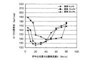
この試験において、炉中心位置での酸素流速Vとコークス原単位との関係を調べた結果を図3に示す。ここで、コークス原単位が低いということは、炉中心部側の領域を含めた炉径方向全般でのガス流れが適正化し、これによりコークスの燃焼と鉄系スクラップの溶解が炉全体で適切に生じていることを意味する。図3によれば、酸素富化率Aを5vol%、15vol%、25vol%と変化させているが、どの酸素富化率においても、コークス原単位を少なくなる最適な酸素流速Vの領域が存在することが判る。炉中心位置での酸素流速Vが小さすぎる領域では、酸素が炉内部まで届きにくいためガス流れが十分でなく、熱不足となるためコークス原単位が増加するものと考えられる。一方、炉中心位置での酸素流速Vが大きすぎる領域では、複数の羽口3の酸素噴射ノズル6から噴射された酸素ジェットが干渉し合い、ガスの流れが不安定となるため、スクラップの溶解が不安定となり、この場合もコークス原単位が増加するものと考えられる。 FIG. 3 shows the results of examining the relationship between the oxygen flow rate V at the furnace center position and the coke unit in this test. Here, the low coke basic unit means that the gas flow in the entire furnace radial direction including the area on the furnace center side is optimized, so that the combustion of coke and the melting of iron-based scrap are properly performed throughout the furnace. It means that it has occurred. According to FIG. 3, the oxygen enrichment rate A is changed to 5 vol%, 15 vol%, and 25 vol%, but there exists an optimal oxygen flow velocity V region in which the coke basic unit is reduced at any oxygen enrichment rate. I know that In the region where the oxygen flow velocity V at the center of the furnace is too small, it is considered that the oxygen does not reach the inside of the furnace and the gas flow is not sufficient, and the coke intensity increases because of insufficient heat. On the other hand, in the region where the oxygen flow velocity V at the furnace center position is too large, the oxygen jets injected from the oxygen injection nozzles 6 of the plurality of tuyere 3 interfere with each other and the gas flow becomes unstable, so that the melting of the scrap Becomes unstable, and in this case as well, it is considered that the basic unit of coke increases.
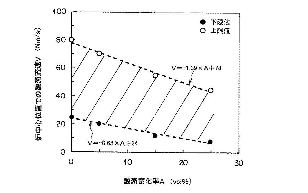
また、炉中心位置での最適な酸素流速Vは、酸素富化率Aに伴い変化しており、酸素富化率Aが増加すると、酸素流速Vの最適領域は低流速側へシフトすることが判る。これは、酸素富化率が高くなると羽口前温度が高くなるため、炉径方向での温度分布が大きくなり、ガスの流れの制御が重要になるためであると考えられる。図3に示すコークス原単位が少ない最適な範囲(150kg/t・pig以下)の炉中心位置での最適な酸素流速Vの上限値と下限値を、酸素富化率Aに応じて整理すると図4のようになる。図4には、上限値と下限値の点とともに、回帰式で数値化した線を示した。回帰した2つの直線に挟まれた斜線部の範囲、すなわち上記(1)式を満足する領域が、コークスの原単位が少なくなる、炉中心位置での酸素流速Vと酸素富化率Aの最適領域である。 Further, the optimum oxygen flow rate V at the furnace center position varies with the oxygen enrichment rate A, and when the oxygen enrichment rate A increases, the optimum region of the oxygen flow rate V may shift to the lower flow rate side. I understand. This is presumably because the temperature before the tuyere increases as the oxygen enrichment rate increases, so that the temperature distribution in the furnace radial direction increases and control of the gas flow becomes important. The upper limit and lower limit of the optimum oxygen flow velocity V at the furnace center position in the optimum range (150 kg / t · pig or less) with a small coke basic unit shown in FIG. It becomes like 4. FIG. 4 shows a line quantified by the regression equation together with the upper limit value and the lower limit value. The range of the shaded area between the two regression lines, that is, the area satisfying the above equation (1) is the optimum of the oxygen flow rate V and the oxygen enrichment rate A at the furnace center position where the basic unit of coke is reduced. It is an area.
なお、酸素富化率Aに特に制限はないが、送風酸素富化の効果を得るためには、一般には2vol%以上の酸素富化率とすることが好ましい。一方、酸素富化率が過剰であると、羽口前温度の上昇によって羽口抜熱量が徒に増大するとともに、羽口耐火物の溶損頻度が増大するおそれがある。また、炉径方向での温度分布が大きくなってガス流れの制御が困難になる等の問題を生じやすい。このため酸素富化率は50vol%程度を上限とするのが好ましい。 In addition, although there is no restriction | limiting in particular in the oxygen enrichment rate A, in order to acquire the effect of blast oxygen enrichment, it is generally preferable to make it an oxygen enrichment rate of 2 vol% or more. On the other hand, if the oxygen enrichment rate is excessive, the amount of heat extracted from the tuyere increases easily due to the increase in the temperature before the tuyere, and the frequency of melting of the tuyere refractory may increase. In addition, the temperature distribution in the furnace radial direction becomes large, and problems such as difficulty in controlling the gas flow are likely to occur. For this reason, the oxygen enrichment rate is preferably about 50 vol% as the upper limit.
以下、鉄含有ダスト/スラッジ塊成化物の構成成分や製法などについて、それらの好ましい実施形態を説明する。
前記鉄含有ダストは、酸化鉄及び/又は金属鉄を含むダストであり、その種類に特に制限はないが、代表的なものとしては、鉄鋼製造プロセスで生じる製鋼ダストを挙げることができる。この製鋼ダストには、溶銑予備処理工程で生じる溶銑予備処理ダスト、転炉脱炭工程で生じる転炉ダスト、電気炉で生じる電気炉ダストなどが含まれる。これらの製鋼ダストは、製鋼工程で発生した排ガスから集塵することにより回収されたものである。また、これらの中でも、転炉脱炭工程で生じる転炉ダスト、いわゆるOGダストが、不純物の含有量が少なく、したがって鉄含有量が高いため特に好ましい。また、製鋼ダスト以外の鉄含有ダストとしては、例えば、高炉ダスト、圧延ダストなどがある。
また、前記鉄含有スラッジは、酸化鉄及び/又は金属鉄を含むスラッジであり、その種類に特に制限はないが、上述したような各種ダストが湿式集塵機で捕集されることでスラッジ化したものが、代表例として挙げられる。
In the following, preferred embodiments of the constituent components and production method of the iron-containing dust / sludge agglomerated product will be described.
The iron-containing dust is dust containing iron oxide and / or metallic iron, and the type thereof is not particularly limited, but typical examples include steel-making dust generated in a steel manufacturing process. The steelmaking dust includes hot metal pretreatment dust generated in the hot metal pretreatment process, converter dust generated in the converter decarburization process, electric furnace dust generated in the electric furnace, and the like. These steelmaking dusts are collected by collecting dust from the exhaust gas generated in the steelmaking process. Among these, converter dust generated in the converter decarburization step, so-called OG dust, is particularly preferable because it has a low impurity content and therefore a high iron content. Examples of iron-containing dust other than steelmaking dust include blast furnace dust and rolling dust.
The iron-containing sludge is a sludge containing iron oxide and / or metallic iron, and there is no particular limitation on the type thereof, but it is sludge formed by collecting various types of dust as described above with a wet dust collector. Is a typical example.
さきに述べたように、鉄含有ダスト/スラッジ塊成化物は、一般には、鉄含有ダストまたは/および鉄含有スラッジに水硬性バインダーを配合し、さらに必要に応じて還元用の炭材粉などを配合した原料に水を加えて混合した後、成形し、この成形物を水和硬化させることにより得られる。
前記水硬性バインダーとしては、例えば、ポルトランドセメント、高炉セメント、アルミナセメント、フライアッシュセメントなどの各種セメント、高炉水砕スラグ微粉末、生石灰などの1種以上を用いることができる。原料中の水硬性バインダーの配合量は、強度の発現及びスラグ生成量の抑制の観点から、一般に2〜25mass%程度とすることが好ましい。
As described above, the iron-containing dust / sludge agglomerate generally contains a hydraulic binder in the iron-containing dust or / and iron-containing sludge, and further contains carbon powder for reduction as required. It can be obtained by adding water to the blended raw material, mixing, molding, and hydrating and curing the molded product.
As said hydraulic binder, 1 or more types, such as various cements, such as a Portland cement, a blast furnace cement, an alumina cement, a fly ash cement, blast furnace granulated slag fine powder, quick lime, can be used, for example. In general, the blending amount of the hydraulic binder in the raw material is preferably about 2 to 25 mass% from the viewpoints of strength development and suppression of slag generation.
前記炭材粉とは炭素を主成分とする粉体のことであり、竪型溶解炉中で酸化鉄の還元材となる。一般に、製鉄用の竪型溶解炉では還元材として塊コークスが用いられるが、塊コークスよりもコークス粉などの炭材粉の方が価格が安く、コスト的に有利なことに加え、酸化鉄と炭素の接触面積が増大するため、酸化鉄の還元反応も速やかに進行する利点がある。炭材粉としては、コークス粉、石炭粉(好ましくは無煙炭粉)、プラスチック粉などの1種以上を用いることができるが、特に、コークス粉などのように揮発分が少ないものが好ましい。また、鉄含有ダスト/スラッジ塊成化物中に大きな炭材が存在すると、その部分から亀裂が生じ、強度を低下させる原因となるため、炭材粉は粒径3mm以下が好ましい。原料中の炭材粉の配合量は、一般に2〜25mass%程度が好ましい。 The carbonaceous material powder is a powder mainly composed of carbon, and becomes a reducing material for iron oxide in a vertical melting furnace. Generally, lump coke is used as a reducing material in a vertical melting furnace for iron making, but carbon powder such as coke powder is less expensive and advantageous in terms of cost than lump coke. Since the contact area of carbon increases, there is an advantage that the reduction reaction of iron oxide proceeds rapidly. As the carbonaceous material powder, one or more types such as coke powder, coal powder (preferably anthracite coal powder), plastic powder and the like can be used, and those having a low volatile content such as coke powder are particularly preferable. Further, if a large carbon material is present in the iron-containing dust / sludge agglomerated material, cracks are generated from the portion, which causes a decrease in strength. Therefore, the carbon material powder preferably has a particle size of 3 mm or less. In general, the blending amount of the carbonaceous powder in the raw material is preferably about 2 to 25 mass%.
また、鉄含有ダスト/スラッジ塊成化物の原料中には、上述した鉄含有ダストまたは/および鉄含有スラッジ、水硬性バインダーおよび炭材粉以外の材料を必要に応じて適宜配合してもよい。例えば、硬化速度調整剤、界面活性剤、ベントナイト、さらには、鉄含有ダスト/スラッジ塊成化物の圧縮強度を高めるための塩化物、原料に適度な粒度分布を与えて成型性を高めるための材料として焼結篩下粉、ミルスケールなどの鉄含有粉粒物、スラグの塩基度を調整するための石灰石、硅石などの粉粒物などの1種以上を配合してもよい。
また、生成するスラグ量をなるべく少なくするという観点から、原料中でのSiO2、Al2O3、CaO、MgOの合計量を25mass%以下とすることが好ましい。当然、これら成分は水硬性バインダーなどに含有されるものも含まれる。
Further, in the raw material of the iron-containing dust / sludge agglomerated material, materials other than the iron-containing dust or / and iron-containing sludge, hydraulic binder and carbonaceous powder described above may be appropriately blended as necessary. For example, curing rate modifiers, surfactants, bentonites, chlorides for increasing the compressive strength of iron-containing dust / sludge agglomerates, materials for imparting an appropriate particle size distribution to the raw materials and enhancing moldability As an additive, one or more of iron-containing granular materials such as sintered sieve powder and mill scale, and limestone for adjusting the basicity of slag, and granular materials such as meteorite may be blended.
Further, from the viewpoint of reducing the amount of slag to be generated as much as possible, the total amount of SiO 2 , Al 2 O 3 , CaO, and MgO in the raw material is preferably set to 25 mass% or less. Of course, these components include those contained in hydraulic binders.
水硬性バインダーを用いて鉄含有ダスト/スラッジ塊成化物を得るには、上述した原料に水を加えて混合した後、成形し、この成形物を水和硬化させる。
水の量は原料の配合によっても異なるが、成形時に圧縮しても水がしみ出てこない最大水量が望ましい。定量的には、JIS−A−1101(コンクリートのスランプ測定方法)に準じた測定においてスランプが0である最大水量となるように調整することが好ましい。水の量が少なすぎると適切に成形できず、また水硬性バインダーの硬化も進行しない。一方、水の量が多すぎて成形時に水がしみ出てくると、その水の処理などに特別な対応が必要になるからである。
In order to obtain an iron-containing dust / sludge agglomerate using a hydraulic binder, water is added to the above-mentioned raw material and mixed, then molded, and this molded product is hydrated and cured.
Although the amount of water varies depending on the composition of the raw material, the maximum amount of water that does not ooze out even when compressed during molding is desirable. Quantitatively, it is preferable to adjust the slump so that the maximum water amount is zero in the measurement according to JIS-A-1101 (method of measuring concrete slump). If the amount of water is too small, it cannot be molded properly, and curing of the hydraulic binder does not proceed. On the other hand, if the amount of water is too large and water oozes out during molding, special measures are required for the treatment of the water.
成形工程は、型枠を用いた成形、押し出し成形、ロールプレス成形など任意の方式で行うことができるが、成形物を高密度にすると鉄含有ダスト/スラッジ塊成化物は高強度化する傾向があるため、できるだけ高密度化に成形することが好ましい。このため原料と水の混合物を圧縮成形し、または加振しつつ圧縮成形することが好ましい。具体的には、ブリケット成形機、プレス成形機、押出成形機などのような圧縮成形機や、これに加振機能を持たせたものなどを用いて成形することが好ましい。
成形物の形状は任意であるが、炉に装入した際の粉化をなるべく抑えるために角部が少ない方が好ましい。また、成形物の大きさも任意であるが、あまり小さいと竪型溶解炉に装入した際に炉の圧力損失を増大させ、一方、あまり大きいと竪型溶解炉に装入した際に塊成化物の中心部の昇温遅れによる還元・溶解遅れを生じるので、一般には容積で20〜2000cm3程度のサイズが好ましい。
The molding process can be performed by any method such as molding using a mold, extrusion molding, roll press molding, etc. However, if the molding is made dense, the iron-containing dust / sludge agglomerate tends to increase in strength. For this reason, it is preferable to mold as high a density as possible. For this reason, it is preferable to compression-mold the mixture of raw material and water or to perform compression molding while vibrating. Specifically, it is preferable to perform molding using a compression molding machine such as a briquette molding machine, a press molding machine, an extrusion molding machine, or the like having a vibration function.
Although the shape of a molded product is arbitrary, in order to suppress powdering at the time of charging to a furnace as much as possible, it is preferable that there are few corners. Also, the size of the molded product is arbitrary, but if it is too small, the pressure loss of the furnace will increase when it is charged into the vertical melting furnace, while if it is too large, it will agglomerate when charged in the vertical melting furnace. In general, a size of about 20 to 2000 cm 3 in volume is preferable because a reduction and dissolution delay due to a temperature rise delay in the center of the compound occurs.
原料と水の混合物を成形して得られた成形物は、水硬性バインダーにより水和硬化させるため、一定期間養生させる。この養生の方法や期間は任意であり、例えば、蒸気による一次養生を行った後、大気下での二次養生を行ってもよい。養生期間は、養生スペースや生産性などの面からはなるべく短い方が好ましいが、養生後の必要強度に応じて適宜選択すればよい。一般には1〜7日間程度が好ましい。
また、鉄含有ダスト/スラッジ塊成化物としては、上述したような水硬性バインダーを用いて成形体を水和硬化させる製法以外の方法で製造されたものでもよい。
A molded product obtained by molding a mixture of a raw material and water is cured for a certain period of time in order to be hydrated and cured by a hydraulic binder. The curing method and period may be arbitrary. For example, after performing primary curing with steam, secondary curing in the atmosphere may be performed. The curing period is preferably as short as possible from the aspects of curing space and productivity, but may be appropriately selected according to the required strength after curing. Generally, about 1 to 7 days is preferable.
Further, the iron-containing dust / sludge agglomerate may be produced by a method other than the production method in which the molded body is hydrated and cured using a hydraulic binder as described above.
1 炉体
2 原料装入部
3 羽口
4 熱風管
5 排気ダクト
6 酸素噴射ノズル
7 集塵装置
30 羽口管
DESCRIPTION OF SYMBOLS 1 Furnace 2 Raw material charging part 3 Tuyere 4 Hot air pipe 5 Exhaust duct 6 Oxygen injection nozzle 7
Claims (2)
少なくとも一部の羽口内に、酸素を超音速で噴射する酸素噴射ノズルを配置し、羽口から熱風を吹き込みつつ、前記酸素噴射ノズルから下記(1)式を満足するように酸素を吹き込むことを特徴とする竪型溶解炉を用いた溶銑製造方法。
−0.68×A+24≦V≦−1.39×A+78 …(1)
但し、
A:酸素富化率(vol%)=([酸素噴射ノズルから吹き込まれる酸素流量]/[熱風流量])×100
V:酸素噴射ノズルから吹き込まれる酸素の炉中心位置での流速(Nm/s) In a vertical melting furnace, iron scrap and coke are charged from the top of the furnace, hot air is blown from a plurality of tuyere at the bottom of the furnace, and iron scrap is produced by melting iron scrap with the combustion heat of the coke. A way to
An oxygen injection nozzle that injects oxygen at a supersonic speed is disposed in at least some tuyere, and oxygen is blown from the oxygen jet nozzle so as to satisfy the following formula (1) while blowing hot air from the tuyere. A hot metal production method using the vertical type melting furnace.
−0.68 × A + 24 ≦ V ≦ −1.39 × A + 78 (1)
However,
A: Oxygen enrichment rate (vol%) = ([Oxygen flow rate blown from oxygen injection nozzle] / [Hot air flow rate]) × 100
V: Flow velocity of oxygen blown from the oxygen injection nozzle at the furnace center position (Nm / s)
Priority Applications (1)
| Application Number | Priority Date | Filing Date | Title |
|---|---|---|---|
| JP2008171521A JP5515242B2 (en) | 2008-06-30 | 2008-06-30 | Hot metal production method using vertical melting furnace |
Applications Claiming Priority (1)
| Application Number | Priority Date | Filing Date | Title |
|---|---|---|---|
| JP2008171521A JP5515242B2 (en) | 2008-06-30 | 2008-06-30 | Hot metal production method using vertical melting furnace |
Publications (3)
| Publication Number | Publication Date |
|---|---|
| JP2010008028A true JP2010008028A (en) | 2010-01-14 |
| JP2010008028A5 JP2010008028A5 (en) | 2012-09-06 |
| JP5515242B2 JP5515242B2 (en) | 2014-06-11 |
Family
ID=41588738
Family Applications (1)
| Application Number | Title | Priority Date | Filing Date |
|---|---|---|---|
| JP2008171521A Expired - Fee Related JP5515242B2 (en) | 2008-06-30 | 2008-06-30 | Hot metal production method using vertical melting furnace |
Country Status (1)
| Country | Link |
|---|---|
| JP (1) | JP5515242B2 (en) |
Citations (5)
| Publication number | Priority date | Publication date | Assignee | Title |
|---|---|---|---|---|
| JPS57148175A (en) * | 1981-01-21 | 1982-09-13 | Union Carbide Corp | Ultrasonic injection of oxygen for cupora |
| JPS63196095U (en) * | 1987-06-08 | 1988-12-16 | ||
| JPH11504707A (en) * | 1996-03-04 | 1999-04-27 | ゲオルク フィッシャー ディサ エンジニアリング アー ゲー | A method for smelting metallic raw materials in a shaft furnace |
| JP2000204409A (en) * | 1999-01-13 | 2000-07-25 | Nippon Steel Corp | Operation of vertical furnace |
| JP2007002305A (en) * | 2005-06-24 | 2007-01-11 | Nippon Chutetsukan Kk | Method for smelting molten pig iron using cupola |
-
2008
- 2008-06-30 JP JP2008171521A patent/JP5515242B2/en not_active Expired - Fee Related
Patent Citations (5)
| Publication number | Priority date | Publication date | Assignee | Title |
|---|---|---|---|---|
| JPS57148175A (en) * | 1981-01-21 | 1982-09-13 | Union Carbide Corp | Ultrasonic injection of oxygen for cupora |
| JPS63196095U (en) * | 1987-06-08 | 1988-12-16 | ||
| JPH11504707A (en) * | 1996-03-04 | 1999-04-27 | ゲオルク フィッシャー ディサ エンジニアリング アー ゲー | A method for smelting metallic raw materials in a shaft furnace |
| JP2000204409A (en) * | 1999-01-13 | 2000-07-25 | Nippon Steel Corp | Operation of vertical furnace |
| JP2007002305A (en) * | 2005-06-24 | 2007-01-11 | Nippon Chutetsukan Kk | Method for smelting molten pig iron using cupola |
Also Published As
| Publication number | Publication date |
|---|---|
| JP5515242B2 (en) | 2014-06-11 |
Similar Documents
| Publication | Publication Date | Title |
|---|---|---|
| US10407744B2 (en) | Production method of granular metallic iron | |
| KR100498100B1 (en) | A method for making molten iron by using hot compaction of fine dri and calcined additives in non-coking coal based iron making process | |
| JP5262354B2 (en) | Hot metal production method using vertical melting furnace | |
| JP5515242B2 (en) | Hot metal production method using vertical melting furnace | |
| JP2004183070A (en) | Method for producing molten iron | |
| JP5439756B2 (en) | Hot metal production method using vertical melting furnace | |
| JP5181875B2 (en) | Hot metal production method using vertical melting furnace | |
| JP5181878B2 (en) | Hot metal production method | |
| JP5251296B2 (en) | Hot metal production method using vertical melting furnace | |
| JP5125819B2 (en) | Vertical melting furnace and hot metal manufacturing method | |
| JP5910182B2 (en) | Hot metal manufacturing method using vertical melting furnace | |
| WO2016173248A1 (en) | Flash ironmaking system and method | |
| JP5082678B2 (en) | Hot metal production method using vertical scrap melting furnace | |
| JP5251297B2 (en) | Hot metal production method using vertical melting furnace | |
| JP5867428B2 (en) | Hot metal manufacturing method using vertical melting furnace | |
| JP2010008030A (en) | Molten-metal production method using vertical melting furnace | |
| JP4992549B2 (en) | Hot metal production method using vertical scrap melting furnace | |
| JP5200422B2 (en) | Hot metal production method using vertical scrap melting furnace | |
| JP5862514B2 (en) | Scrap melting vertical furnace operation method | |
| JP2007204825A (en) | Method for producing molten iron | |
| JP5867427B2 (en) | Hot metal manufacturing method using vertical melting furnace | |
| JP2014015653A (en) | Pig iron production method and pig iron production furnace | |
| RU2395585C1 (en) | Procedure for blast furnace melting | |
| JP6295796B2 (en) | Sinter ore manufacturing method | |
| JP2015054991A (en) | Method for manufacturing sintering raw material |
Legal Events
| Date | Code | Title | Description |
|---|---|---|---|
| A621 | Written request for application examination |
Free format text: JAPANESE INTERMEDIATE CODE: A621 Effective date: 20110421 |
|
| A521 | Request for written amendment filed |
Free format text: JAPANESE INTERMEDIATE CODE: A523 Effective date: 20120724 |
|
| A131 | Notification of reasons for refusal |
Free format text: JAPANESE INTERMEDIATE CODE: A131 Effective date: 20121002 |
|
| A521 | Request for written amendment filed |
Free format text: JAPANESE INTERMEDIATE CODE: A523 Effective date: 20121126 |
|
| A131 | Notification of reasons for refusal |
Free format text: JAPANESE INTERMEDIATE CODE: A131 Effective date: 20130402 |
|
| A521 | Request for written amendment filed |
Free format text: JAPANESE INTERMEDIATE CODE: A523 Effective date: 20130531 |
|
| A521 | Request for written amendment filed |
Free format text: JAPANESE INTERMEDIATE CODE: A821 Effective date: 20130531 |
|
| TRDD | Decision of grant or rejection written | ||
| A01 | Written decision to grant a patent or to grant a registration (utility model) |
Free format text: JAPANESE INTERMEDIATE CODE: A01 Effective date: 20140304 |
|
| A61 | First payment of annual fees (during grant procedure) |
Free format text: JAPANESE INTERMEDIATE CODE: A61 Effective date: 20140317 |
|
| R150 | Certificate of patent or registration of utility model |
Ref document number: 5515242 Country of ref document: JP Free format text: JAPANESE INTERMEDIATE CODE: R150 |
|
| R250 | Receipt of annual fees |
Free format text: JAPANESE INTERMEDIATE CODE: R250 |
|
| R250 | Receipt of annual fees |
Free format text: JAPANESE INTERMEDIATE CODE: R250 |
|
| LAPS | Cancellation because of no payment of annual fees |