JP2010007812A - Vibration damping device and measuring device with this - Google Patents
Vibration damping device and measuring device with this Download PDFInfo
- Publication number
- JP2010007812A JP2010007812A JP2008170156A JP2008170156A JP2010007812A JP 2010007812 A JP2010007812 A JP 2010007812A JP 2008170156 A JP2008170156 A JP 2008170156A JP 2008170156 A JP2008170156 A JP 2008170156A JP 2010007812 A JP2010007812 A JP 2010007812A
- Authority
- JP
- Japan
- Prior art keywords
- vibration
- metal plate
- vibration isolation
- measurement
- measuring device
- Prior art date
- Legal status (The legal status is an assumption and is not a legal conclusion. Google has not performed a legal analysis and makes no representation as to the accuracy of the status listed.)
- Granted
Links
Images


Abstract
Description
本発明は、高い分解能が要求される測定器に対し外部からの振動を伝達し難くするための除振装置及びこれを有する測定装置に関するものである。 The present invention relates to a vibration isolator for making it difficult to transmit external vibration to a measuring instrument that requires high resolution, and a measuring apparatus having the same.
例えば、高い分解能が要求される測定器としては、特許文献1に係る光熱変換測定装置が知られている。この種の測定器では、測定する実験環境下で発生する振動や音等のノイズ源によって背景測定信号(バックグランドノイズ)が増加することに応じて測定器の測定性能が劣化するという問題がある。
For example, a photothermal conversion measuring apparatus according to
このようなノイズ源を低減する対策として、例えば、特許文献2に開示されるようなアクティブ型除振装置を用いることが考えられる。特許文献2のアクティブ型除振装置は、定盤に伝わった振動を振動センサにより検出し、この検出結果に基づいて上記振動を除去するための駆動量を演算し、この駆動量に応じてアクチュエータ(底盤)を駆動させるようになっている。
しかしながら、特許文献2に係るアクティブ型除振装置は、検出された振動をアクチュエータの駆動量としてフィードバックするための精密な電気系統を要するため、その調整やメンテナンスの負担が大きく、除振装置自体が高価になるという問題があった。
However, since the active vibration isolator according to
また、特許文献2に係るアクティブ型除振装置は、振動を打ち消すためにアクチュエータを積極的に駆動する構成であるため、上述のように高い分解能が要求される測定器にとって、このような積極的な振動が却って測定精度を低下させる要因ともなりかねない。
Further, the active vibration isolator according to
本発明は、上記課題に鑑みてなされたものであり、調整やメンテナンスの負担が小さく、自ら振動を生じさせることなく外部からの振動が測定器に伝達するのを抑制することができる除振装置及びこれを備えた測定装置を提供することを目的としている。 The present invention has been made in view of the above problems, and is a vibration isolation device that can reduce the burden of adjustment and maintenance, and can prevent external vibrations from being transmitted to a measuring instrument without causing vibrations by itself. And it aims at providing a measuring device provided with this.
上記課題を解決するために本発明は、設置面と測定器との間に設けられ、前記設置面からの振動が前記測定器に伝達するのを抑制するための除振装置であって、前記設置面上に設置される第一金属板と、前記第一金属板の上に設けられた第二金属板と、前記第一金属板と第二金属板との間に挟持され、前記第一金属板からの振動を受けて弾性変形可能な弾性部材と、前記第二金属板上に設けられ、その上面に前記測定器の少なくとも一部が載置されるとともに、前記第二金属板からの振動に応じて少なくとも一部が弾性変形することにより、前記振動を吸収することが可能な除振台とを備え、前記第一金属板、弾性部材及び第二金属板により吸収される振動の周波数の帯域と、前記除振台により吸収される振動の周波数の帯域とが異なることを特徴とする除振装置を提供する。 In order to solve the above problems, the present invention is a vibration isolator provided between an installation surface and a measuring instrument for suppressing vibrations from the installation surface from being transmitted to the measuring instrument, A first metal plate installed on an installation surface, a second metal plate provided on the first metal plate, and sandwiched between the first metal plate and the second metal plate; An elastic member that can be elastically deformed in response to vibration from the metal plate and provided on the second metal plate, and at least a part of the measuring device is placed on the upper surface of the elastic member, and from the second metal plate A vibration isolation table capable of absorbing the vibration by elastically deforming at least a part in response to the vibration, and a frequency of vibration absorbed by the first metal plate, the elastic member, and the second metal plate And the frequency band of vibration absorbed by the vibration isolation table are different. Providing anti-vibration apparatus is characterized.
本発明に係る除振装置によれば、第一金属板と第二金属板との間に設けられた弾性部材及び除振台の少なくとも一部の弾性変形により、設置面からの振動を吸収することができるので、アクティブ除振台と異なり電気的な調整が不要となり、メンテナンスの負担を軽減することができる。 According to the vibration isolator of the present invention, the elastic member provided between the first metal plate and the second metal plate and the elastic deformation of at least a part of the vibration isolation table absorb vibration from the installation surface. Therefore, unlike the active vibration isolation table, no electrical adjustment is required, and the burden of maintenance can be reduced.
また、本発明では、除振装置自体が積極的に振動することなく、設置面からの振動を吸収することができるので、高い分解能が要求される測定器を載置する場合において自らの振動により測定精度を低下させるという事態を回避することができる。 Further, in the present invention, since the vibration isolator itself can absorb vibrations from the installation surface without actively vibrating, when the measuring instrument requiring high resolution is placed, A situation in which the measurement accuracy is lowered can be avoided.
さらに、本発明では、第一及金属板、第二金属板及び弾性部材により吸収される振動の周波数帯域と、除振台により吸収される振動の周波数帯域とが異なるものにされているため、アクティブ除振台を使用しなくても、幅広い周波数帯域の振動を吸収することが可能となり、除振性能を向上することができる。 Furthermore, in the present invention, the frequency band of vibration absorbed by the first metal plate, the second metal plate and the elastic member is different from the frequency band of vibration absorbed by the vibration isolation table. Even if an active vibration isolation table is not used, vibrations in a wide frequency band can be absorbed, and the vibration isolation performance can be improved.
前記除振装置において、前記除振台は、前記第二金属板に取り付けられる本体部と、前記測定器の少なくとも一部が載置される載置部と、前記本体部と載置部との間に設けられた空気室とを備え、前記空気室の容積変化によって前記振動を吸収することが好ましい。 In the vibration isolation device, the vibration isolation table includes a main body portion attached to the second metal plate, a mounting portion on which at least a part of the measuring device is mounted, and the main body portion and the mounting portion. It is preferable that the vibration chamber be absorbed by a change in volume of the air chamber.
この構成によれば、空気室内の空気の圧縮弾性を利用した空気ばねによって、本体部と載置部との間で振動を吸収することができる。 According to this configuration, vibration can be absorbed between the main body portion and the mounting portion by the air spring using the compression elasticity of the air in the air chamber.
前記除振装置において、前記第一金属板、第二金属板のうちの少なくとも第一金属板は、前記測定器よりも大きな重量を有することが好ましい。 In the vibration isolation device, it is preferable that at least the first metal plate of the first metal plate and the second metal plate has a weight larger than that of the measuring device.
この構成によれば、測定器よりも大きな重量を有する第一金属板を介して測定器を設置するため、測定器だけを設置する場合と比較して、設置面に与えられる重量が大きなものとなり、当該設置面に対して測定器が移動し難くなる。したがって、設置面からの振動が第一金属板を介して測定器に伝わるのをより有効に抑制することができる。 According to this configuration, since the measuring device is installed through the first metal plate having a weight larger than that of the measuring device, the weight given to the installation surface is larger than when only the measuring device is installed. This makes it difficult for the measuring instrument to move relative to the installation surface. Therefore, it can suppress more effectively that the vibration from an installation surface is transmitted to a measuring device via a 1st metal plate.
また、本発明は、前記除振装置と、前記除振装置の除振台上に少なくとも一部が載置される測定器とを備えていることを特徴とする測定装置を提供する。 In addition, the present invention provides a measurement apparatus comprising the vibration isolation device and a measuring instrument that is at least partially placed on a vibration isolation table of the vibration isolation device.
本発明に係る測定装置によれば、上述のように調整やメンテナンスの負担が小さく、自ら振動を生じさせることなく設置面からの振動が測定器に伝達するのを抑制することができる。 According to the measuring apparatus according to the present invention, as described above, the burden of adjustment and maintenance is small, and it is possible to suppress vibration from the installation surface from being transmitted to the measuring instrument without causing vibration on its own.
前記測定装置において、前記測定器は、測定対象物に照射される断続光を生成するためのメカニカルチョッパと、前記断続光による測定対象物の変化を測定するための測定部とを備え、前記メカニカルチョッパ又は測定部の一方が前記除振台上に、他方が前記第二金属板上に分けて配置されていることが好ましい。 In the measuring apparatus, the measuring device includes a mechanical chopper for generating intermittent light irradiated to the measurement object, and a measurement unit for measuring a change in the measurement object due to the intermittent light, and the mechanical It is preferable that one of the chopper and the measuring unit is arranged on the vibration isolation table and the other is arranged on the second metal plate.
このようにすれば、測定対象物の変化を測定するための測定部と、振動源となるメカニカルチョッパとが、除振台と第二金属板とに分けて配置されているので、メカニカルチョッパにより振動が生じたとしても、この振動は、除振台に吸収されて測定部に伝わり難くなる。したがって、測定部の測定精度の低下を抑制することができる。 In this way, since the measurement unit for measuring the change of the measurement object and the mechanical chopper as the vibration source are arranged separately in the vibration isolation table and the second metal plate, the mechanical chopper Even if vibration occurs, this vibration is absorbed by the vibration isolation table and is difficult to be transmitted to the measurement unit. Therefore, it is possible to suppress a decrease in measurement accuracy of the measurement unit.
特に、前記メカニカルチョッパは、前記第二金属板上に載置され、前記測定部は、前記除振台上に載置されていることが好ましい。 In particular, it is preferable that the mechanical chopper is placed on the second metal plate, and the measurement unit is placed on the vibration isolation table.
このようにすれば、上述のようにメカニカルチョッパから測定部への振動の伝達を抑制しながら、高い分解能が要求される測定部については、各金属板、弾性部材及び除振台によって設置面からの振動を吸収することができるため、測定部による測定精度の低下をより有効に阻止することができる。 If it does in this way, about the measuring part which requires high resolution, suppressing transmission of vibration from a mechanical chopper to a measuring part as mentioned above, it will be from an installation surface by each metal plate, an elastic member, and a vibration isolator. Therefore, it is possible to more effectively prevent a decrease in measurement accuracy by the measurement unit.
そして、前記測定部は、前記断続光が照射された前記測定対象物の照射部位に測定光を照射するとともに、前記照射部位を通過する前後における測定光の位相変化を測定するように構成することができる。 And the said measurement part is comprised so that the phase change of the measurement light before and behind passing through the said irradiation site | part may be measured while irradiating the measurement site | part to the irradiation site | part of the said measurement object irradiated with the said intermittent light Can do.
このようにすれば、測定対象物に含まれる所定の成分の定量分析を行うことができる。その原理は以下の通りである。 In this way, it is possible to perform a quantitative analysis of a predetermined component contained in the measurement object. The principle is as follows.
前記所定の成分を励起させるための波長を有する光を前記断続光として選択し、この断続光を測定対象成分の照射部位に照射することにより、測定対象成分内において光熱効果による屈折率変化が生じる。この屈折率変化の程度は、前記照射部位を通過する前後における測定光の位相変化に比例するため、前記位相変化を測定することにより、前記測定対象成分内における所定の成分の定量分析を行うことができる。 By selecting light having a wavelength for exciting the predetermined component as the intermittent light, and irradiating this intermittent light to the irradiation site of the measurement target component, a refractive index change due to the photothermal effect occurs in the measurement target component. . Since the degree of the refractive index change is proportional to the phase change of the measurement light before and after passing through the irradiation site, a quantitative analysis of a predetermined component in the measurement target component is performed by measuring the phase change. Can do.
本発明によれば、調整やメンテナンスの負担が小さく、自ら振動を生じさせることなく外部からの振動が測定器に伝達するのを抑制することができる。 ADVANTAGE OF THE INVENTION According to this invention, the burden of adjustment and a maintenance is small, and it can suppress that the vibration from the outside transmits to a measuring device, without producing a vibration by itself.
以下、本発明の好ましい実施形態について図面を参照して説明する。 Hereinafter, preferred embodiments of the present invention will be described with reference to the drawings.
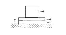
図1は、本発明の実施形態に係る測定装置を示す概略正面図である。 FIG. 1 is a schematic front view showing a measuring apparatus according to an embodiment of the present invention.
図1を参照して、測定装置は、所定の設置面T上に設けられた除振装置1と、この除振装置1の上に載置された測定器6とを備えている。
With reference to FIG. 1, the measurement apparatus includes a
除振装置1は、設置面T上に設置される第一金属板2と、この第一金属板2の上に設けられた第二金属板4と、第一金属板2と第二金属板4との間に挟持された複数の防振ゴム(弾性部材)3と、第二金属板4上に設けられた除振台5とを備えている。
The
各金属板2、4は、本実施形態では鉄板からなる。詳しくは後述するが、除振装置1の除振性能は、各金属板2、4の重量が大きい程向上するため、各金属板2、4としてはできるだけ比重の高い材料(例えば、金)を用いることが好ましい。具体的に、本実施形態において、各金属板2、4は、それぞれ測定器6よりも大きな重量とされている。
Each
防振ゴム3は、前記第一金属板2からの振動を受けて弾性変形可能に構成されている。防振ゴム3の形状としては、ブロック状でも、シート状でもよい。
The
図2は、図1の除振台5の構成を示す正面断面図である。 FIG. 2 is a front sectional view showing the configuration of the vibration isolation table 5 of FIG.
図2を参照して、除振台5は、前記第二金属板4に取り付けられる本体部30と、この本体部30に設けられたダイヤフラム31及び封止部材32と、前記測定器6が載置される載置部33とを備えている。
Referring to FIG. 2, the vibration isolation table 5 includes a
本体部30は、上方に開口する有底容器状に形成され、上下方向の途中部に設けられた隔壁35と、この隔壁35の中央部から上方に突出する突出部36と、この突出部36及び隔壁35を上下に貫通する貫通孔37とを備えている。
The
ダイヤフラム31は、前記貫通孔37内に配置される筒状部分38と、この筒状部分の縁部であって前記突出部36の外側に折り返された折り返し部39とを有し、弾性変形可能な材質からなる。
The
封止部材32は、前記ダイヤフラム31を挟んで突出部36の外側に上から被せられる部材であり、前記筒状部材38に対応する位置で上下に貫通する挿通孔40を備えている。この封止部材32の内側面と前記突出部36の外側面との間でダイヤフラム31(折り返し部39)が挟持されることにより、前記本体部30内部には、空気室S1が形成される。
The sealing
載置部33は、前記測定器5が載置される載置テーブル41と、この載置テーブル41から下に延びる支持棒34とを備えている。支持棒34は、前記挿通孔40を通して配置され、その先端部がダイヤフラム31の筒状部分38に固定されている。
The
このように構成された除振台5は、本体部30と載置部31とが相対的に変位することによりダイヤフラム31が弾性変形して空気室S1の容積が変動し、これに応じた空気室S1内の空気の圧縮弾性を利用して振動を吸収することができる。
The
図3は、図1の測定器6の全体構成を示す概略図である。
FIG. 3 is a schematic diagram showing the overall configuration of the measuring
図3を参照して、測定器6は、試料11内の分析対象成分を励起させるための励起光学系6aと、前記分析対象成分の定量分析を行うための測定光学系6bと、この測定光学系6bにより検出された信号を処理する信号処理装置27とを備えている。
Referring to FIG. 3, a measuring
励起光学系6aは、励起光(波長533nm、出力100mWのレーザ(YAG倍波)光)を出射する励起光源7と、励起光を断続光にするためのメカニカルチョッパ8と、メカニカルチョッパ8からの励起光を反射するダイクロイックミラー9とを備えている。
The excitation
測定光学系6bは、測定光(例えば、出力1mWのHe−Neレーザ)を出射するレーザ光源13と、測定光の偏波面を調整するための1/2波長板14と、1/2波長板14からの測定光を各偏波P1、P2に分光するための偏光ビームスプレッダ(以下、PSBと称す)15と、各偏波P1、P2の光周波数を変換するための音響光学変調機(以下、AOMと称す)16、17と、各偏波P1、P2を反射するミラー18、19と、各偏波P1、P2を合成するためのPSB20と、PSB20からの偏波P2を通過させるとともに偏波P1を反射するPSB21と、PSB21を通過した偏波P2の偏波面を調整する1/4波長板22と、偏波P2を反射するミラー24と、前記PSB21により反射された偏波P1の偏波面を調整する1/4波長板23と、偏波P1及び前記励起光を集光するためのレンズ10と、試料11を通過した偏波P1を反射するミラー12と、PBS21からの各偏波P1、P2を検出するための光検出器26と、PBS21と光検出器26との間に設けられた偏光板25とを備えている。
The measurement
以下、測定器6の動作について説明する。
Hereinafter, the operation of the measuring
励起光源7から出射された励起光は、メカニカルチョッパ8により所定周期の断続光に変換され、ダイクロイックミラー9で反射するとともに、レンズ10により集光されて試料11に照射される。これにより、試料11が励起光を吸収して発熱し(光熱効果)、その温度上昇によって試料11の屈折率が変化する。
Excitation light emitted from the excitation light source 7 is converted into intermittent light having a predetermined period by the mechanical chopper 8, reflected by the dichroic mirror 9, condensed by the
一方、レーザ光源13から出射する測定光は、1/2波長板14により偏波面が調整され、PBS15によって互いに直交する2偏波P1、P2に分光される。
On the other hand, the measurement light emitted from the
各偏波P1、P2は、AOM16、17によって光周波数がシフトされるとともに、ミラー18、19で反射し、PSB20によって合成される。なお、2偏波P1、P2の周波数差は、例えば、30MHzである。
Each of the polarizations P1 and P2 is shifted in optical frequency by the AOMs 16 and 17, reflected by the
合成された各偏波のうち偏波P2は、PBS21を通過するとともにミラー24で反射して、PBS21に戻る。この際、偏波P2は、1/4偏光板22を2度通過することにより、その偏波面が90°回転することになるため、ミラー24から戻る偏波P2は、PBS21で反射して光検出器26に導かれる。
Of the synthesized polarizations, the polarization P2 passes through the
一方、合成された各偏波のうち偏波P1は、PBS21で反射するとともに、1/4波長板23、ダイクロイックミラー9及びレンズ10を通過して、試料11に入射する。前記励起光は、偏波P1(測定光)の入射部に照射されるように構成されている。
On the other hand, of the synthesized polarized waves, the
試料11を透過した偏波P1は、ミラー12で反射し、再び試料11を透過する。試料11からの偏波P1は、レンズ10、ダイクロイックミラー9、1/4波長板23を通過してPBS21に戻る。ここで、偏波P1は、1/4波長板23を2度通過することにより、その偏波面が90°回転しているため、試料11からの偏波P1は、PBS21を通過して前記偏波P2と合流し、光検出器26へ導かれる。
The polarized light P1 that has passed through the
ここで、PBS21と光検出器26との間に設けられた偏光板25において、互いに光周波数の異なる偏波P1と偏波P2とがそれぞれ観測光と参照光として干渉し、その干渉光の光強度が光検出器26によって電気信号(以下、干渉光強度と称す)に変換される。
Here, in the
信号処理装置27は、前記光検出器26からの干渉光強度に基づいて、試料11内の分析対象成分の量(濃度)を分析するようになっている。以下、その原理について説明する。
The
前記干渉光強度は、次式(1)のようにS2で表される。 The interference light intensity is represented by S2 as shown in the following equation (1).
S2=C1+C2×cos(2π×fb×t+φ)・・・(1)
ここで、C1、C2は、PBS等の光学系や試料11の透過率により定まる定数であり、φは、偏波P1、P2の光路長差による位相差、fbは、偏波P1、P2の周波数差である。この(1)式によれば、干渉光強度S2の変化に基づいて、位相差φの変化を求めることができる。
S2 = C1 + C2 × cos (2π × f b × t + φ) (1)
Here, C1 and C2 are constants determined by the transmittance of the optical system such as PBS and the
次に位相差φと試料11中における分析対象成分の濃度との関係について説明する。前記励起光を照射したときの試料11の発熱量(吸熱量)は、試料11中に含まれる分析対象成分の濃度と比例して高くなり、当該発熱量に応じて偏波P1に対する試料11の屈折率が変化し、この屈折率に応じて前記位相差φ(試料11中の偏波P1の光路長)が変化する。すなわち、試料11中に含まれる分析対象成分の濃度が高いほど、励起光による前記位相差φの変化が大きくなるため、位相差φを特定することにより試料11に含まれる分析対象成分の濃度を求めることができる。
Next, the relationship between the phase difference φ and the concentration of the analysis target component in the
具体的には、分析対象成分の濃度が既知である複数種類の試料11のサンプルを予め準備しておき、各サンプルについて前記測定器6を用いて位相差φを測定し、その位相差φと分析対象成分の濃度との関係を信号処理装置27の記憶部(図示せず)にデータテーブルとして記憶しておく。そして、分析対象となる試料11についての位相差φが測定されたときに、その測定結果と前記データテーブルとに基づいて補間処理等を行うことにより、分析対象成分の濃度を特定することが可能となる。
Specifically, samples of a plurality of types of
そして、前記実施形態では、測定器6が各金属板2、4、防振ゴム3及び除振台5の上に設けられているため、設置面Tからの振動が測定器6に伝わるのを効果的に抑制することが可能となる。その理由は以下の通りである。
And in the said embodiment, since the measuring
本実施形態では、各金属板2、4がそれぞれ測定器6よりも重いものであるため、設置面Tに直接測定器6を設置する場合よりも、設置面Tに与えられる重量が大きなものとなり、測定装置全体が設置面Tに対して移動し難くなる。したがって、設置面からの振動が各金属板2、4を介して測定器6に伝わるのを抑制することができる。さらに、これらの金属板2、4の間には、防振ゴム3が設けられているため、第一金属板2からの振動は、防振ゴム3の弾性変形によって吸収され、測定器6に伝わり難くなる。そして、これら各金属板2、4及び防振ゴム3によって吸収される振動は、比較的高い周波数のものである。
In this embodiment, since each
また、本実施形態では、前記第二金属板4上に除振台5(図2参照)が設けられているため、この除振台5の空気室S1内の空気の圧縮弾性を利用した空気ばねにより、第二金属板4から伝わる比較的低い周波数の振動を吸収することができる。つまり、本実施形態に係る除振装置1においては、各金属板2、4及び防振ゴム3により吸収される振動の周波数帯域と、除振台5により吸収される振動の周波数帯域とが異なるものに設定されているため、設置面Tからの振動が測定器6に伝わるのを有効に抑制することができる。
In the present embodiment, since the vibration isolation table 5 (see FIG. 2) is provided on the
前記のように空気ばねを利用した除振台5は、一般的な除振理論に基き、空気ばねの共振ピークを頂点に、高周波側で高い除振効果を奏する。その一方、前記金属板2,4および前記防振ゴム3は、特にその金属板2,4の重量を利用することにより、前記除振台5では実現することの難しい超低周波域での除振効果を実現する。従って、前記除振台5と、前記金属板2,4および防振ゴム3との組合せが、低周波から高周波に至るまでの広い周波数領域にわたって高い除振効果を得ることを実現する。
The anti-vibration table 5 using the air spring as described above exhibits a high anti-vibration effect on the high frequency side with the resonance peak of the air spring as the apex based on the general anti-vibration theory. On the other hand, the
以上説明したように、前記実施形態によれば、第一金属板2と第二金属板4との間に設けられた防振ゴム3及び除振台5により、電気的な調整を行うことなく設置面Tからの振動を吸収することができるので、メンテナンスの負担を軽減することができる。
As described above, according to the embodiment, the
また、前記実施形態では、除振装置1自体が積極的に振動することなく、設置面Tからの振動を吸収することができるので、高い分解能が要求される測定器6を載置する場合においても自らの振動により測定精度を低下させるという事態を回避することができる。
Moreover, in the said embodiment, since the
さらに、前記実施形態では、各金属板2、4及び防振ゴム3により吸収される振動の周波数帯域と、除振台5により吸収される振動の周波数帯域とが異なるものにされているため、幅広い周波数帯域の振動を吸収することが可能となり、除振性能を向上することができる。
Furthermore, in the above embodiment, the frequency band of vibration absorbed by the
前記実施形態のように、各金属板2、4が測定器6よりも大きな重量を有している構成とすれば、測定器6よりも大きな重量を有する各金属板2、4を介して測定器6を設置するため、測定器6だけを設置する場合と比較して、設置面Tに与えられる重量が大きなものとなり、当該設置面Tに対して測定器6が移動し難くなる。したがって、設置面Tからの振動が金属板2、4を介して測定器6に伝わるのをより有効に抑制することができる。
If each
なお、前記実施形態では、各金属板2、4の双方を測定器6よりも大きな重量としているが、各金属板2、4のうちの少なくとも第一金属板2が測定器6よりも大きな重量を有していれば、上述の効果を奏することができる。
In the embodiment, both the
また、前記実施形態では、図1に示すように、励起光学系6a及び測定光学系6bの双方を含む測定器6の全体を除振台5の上に設けることとしているが、図4に示すように、励起光学系6aを第二金属板4上に、測定光学系6bを除振台5上に設けることが好ましい。
Moreover, in the said embodiment, as shown in FIG. 1, although the
このようにすれば、励起光学系6aのメカニカルチョッパ8から生じる振動が測定光学系6bに伝わるのを抑制することができる。つまり、図4に示す実施形態では、メカニカルチョッパ8を有する励起光学系6aと、高い分解能が要求される測定光学系6bとが別々の部材の上に設けられているため、メカニカルチョッパ8により振動が生じたとしても、この振動は除振台5によって吸収されて測定光学系6bに伝わり難くなる。
In this way, it is possible to suppress the vibration generated from the mechanical chopper 8 of the excitation
特に、図示するように、励起光学系6aを第二金属板4上に、測定光学系6bを除振台5上に設けることとすれば、上述のようにメカニカルチョッパ8から測定光学系6bへの振動の伝達を抑制しながら、高い分解能が要求される測定光学系については、各金属板2、4、防振ゴム3及び除振台5によって設置面からの振動を吸収することができるため、測定光学系6bによる測定精度の低下をより有効に阻止することができる。
In particular, as shown in the figure, if the excitation
以下、設置面Tからの振動が測定器6に伝わるのを抑制することができる他の形態について、図5〜図7を参照して説明する。
Hereinafter, another embodiment capable of suppressing the vibration from the installation surface T from being transmitted to the
まず、図5に示す形態では、図1に示した形態から前記除振台5を省略している。この形態においては、比較的高い周波数帯域の振動を吸収する機能が低下するものの、各金属板2、4及び防振ゴム3によって比較的低い周波数帯域の振動を有効に吸収することができる。
First, in the form shown in FIG. 5, the vibration isolation table 5 is omitted from the form shown in FIG. In this embodiment, although the function of absorbing vibrations in a relatively high frequency band is reduced, vibrations in a relatively low frequency band can be effectively absorbed by the
図6に示す形態では、図1に示した形態から防振ゴム3を省略している。この形態においては、防振ゴム3により吸収されていた振動が除振台5に伝わることになるが、この振動のうち比較的低い周波数帯域を除振台5によって吸収することができる。
In the form shown in FIG. 6, the
図7に示す形態では、図5に示した形態から防振ゴム3を省略している。この形態においては、設置面Tからの振動が各金属板2、4同士の重なる境界面において伝わり難くなるため、設置面Tから測定器6へ振動が伝わるのを抑制することができる。
In the form shown in FIG. 7, the
S1 空気室
T 設置面
1 除振装置
2 第一金属板
3 防振ゴム
4 第二金属板
5 除振台
6 測定器
6a 励起光学系
6b 測定光学系
8 メカニカルチョッパ
S1 Air chamber
Claims (7)
前記設置面上に設置される第一金属板と、
前記第一金属板の上に設けられた第二金属板と、
前記第一金属板と第二金属板との間に挟持され、前記第一金属板からの振動を受けて弾性変形可能な弾性部材と、
前記第二金属板上に設けられ、その上面に前記測定器の少なくとも一部が載置されるとともに、前記第二金属板からの振動に応じて少なくとも一部が弾性変形することにより、前記振動を吸収することが可能な除振台とを備え、
前記第一金属板、弾性部材及び第二金属板により吸収される振動の周波数の帯域と、前記除振台により吸収される振動の周波数の帯域とが異なることを特徴とする除振装置。 A vibration isolator provided between an installation surface and a measuring instrument for suppressing vibration from the installation surface from being transmitted to the measuring instrument;
A first metal plate installed on the installation surface;
A second metal plate provided on the first metal plate;
An elastic member sandwiched between the first metal plate and the second metal plate, and elastically deformable by receiving vibration from the first metal plate;
The vibration is provided on the second metal plate, and at least a part of the measuring device is placed on an upper surface of the second metal plate, and at least a part is elastically deformed according to vibration from the second metal plate. And a vibration isolation table capable of absorbing
A vibration isolation device, wherein a vibration frequency band absorbed by the first metal plate, the elastic member, and the second metal plate is different from a vibration frequency band absorbed by the vibration isolation table.
Priority Applications (1)
| Application Number | Priority Date | Filing Date | Title |
|---|---|---|---|
| JP2008170156A JP5066015B2 (en) | 2008-06-30 | 2008-06-30 | Vibration isolator and measuring apparatus having the same |
Applications Claiming Priority (1)
| Application Number | Priority Date | Filing Date | Title |
|---|---|---|---|
| JP2008170156A JP5066015B2 (en) | 2008-06-30 | 2008-06-30 | Vibration isolator and measuring apparatus having the same |
Publications (2)
| Publication Number | Publication Date |
|---|---|
| JP2010007812A true JP2010007812A (en) | 2010-01-14 |
| JP5066015B2 JP5066015B2 (en) | 2012-11-07 |
Family
ID=41588546
Family Applications (1)
| Application Number | Title | Priority Date | Filing Date |
|---|---|---|---|
| JP2008170156A Expired - Fee Related JP5066015B2 (en) | 2008-06-30 | 2008-06-30 | Vibration isolator and measuring apparatus having the same |
Country Status (1)
| Country | Link |
|---|---|
| JP (1) | JP5066015B2 (en) |
Cited By (2)
| Publication number | Priority date | Publication date | Assignee | Title |
|---|---|---|---|---|
| DK177952B1 (en) * | 2010-04-26 | 2015-02-02 | Baker Hughes Inc | System and method for isolating an interferometer |
| WO2016152108A1 (en) * | 2015-03-25 | 2016-09-29 | 日本電気株式会社 | Light measurement device |
Citations (3)
| Publication number | Priority date | Publication date | Assignee | Title |
|---|---|---|---|---|
| JPS63199938A (en) * | 1987-02-12 | 1988-08-18 | Bridgestone Corp | Vibration-proof supporting device |
| JPH10238588A (en) * | 1997-02-28 | 1998-09-08 | Tokai Rubber Ind Ltd | Damper |
| JP2004301520A (en) * | 2003-03-28 | 2004-10-28 | Kobe Steel Ltd | Photothermal conversion measuting instrument and its method |
-
2008
- 2008-06-30 JP JP2008170156A patent/JP5066015B2/en not_active Expired - Fee Related
Patent Citations (3)
| Publication number | Priority date | Publication date | Assignee | Title |
|---|---|---|---|---|
| JPS63199938A (en) * | 1987-02-12 | 1988-08-18 | Bridgestone Corp | Vibration-proof supporting device |
| JPH10238588A (en) * | 1997-02-28 | 1998-09-08 | Tokai Rubber Ind Ltd | Damper |
| JP2004301520A (en) * | 2003-03-28 | 2004-10-28 | Kobe Steel Ltd | Photothermal conversion measuting instrument and its method |
Cited By (6)
| Publication number | Priority date | Publication date | Assignee | Title |
|---|---|---|---|---|
| DK177952B1 (en) * | 2010-04-26 | 2015-02-02 | Baker Hughes Inc | System and method for isolating an interferometer |
| WO2016152108A1 (en) * | 2015-03-25 | 2016-09-29 | 日本電気株式会社 | Light measurement device |
| JPWO2016152108A1 (en) * | 2015-03-25 | 2018-01-11 | 日本電気株式会社 | Light measuring device |
| US10429244B2 (en) | 2015-03-25 | 2019-10-01 | Nec Corporation | Light measurement device |
| JP2021193378A (en) * | 2015-03-25 | 2021-12-23 | 日本電気株式会社 | Light measuring device |
| JP7359195B2 (en) | 2015-03-25 | 2023-10-11 | 日本電気株式会社 | light measurement device |
Also Published As
| Publication number | Publication date |
|---|---|
| JP5066015B2 (en) | 2012-11-07 |
Similar Documents
| Publication | Publication Date | Title |
|---|---|---|
| JP4431622B2 (en) | Photoacoustic spectroscopic gas detection method and detector for improving measurement accuracy by quartz crystal | |
| FI118548B (en) | Photoacoustic detector | |
| US20070236699A1 (en) | Optical tomography method & device | |
| JPH0236338A (en) | Optoacoustic signal detecting device | |
| Jenderka et al. | Investigation of spatial distribution of sound field parameters in ultrasound cleaning baths under the influence of cavitation | |
| JP5066015B2 (en) | Vibration isolator and measuring apparatus having the same | |
| JP6595702B2 (en) | Laser apparatus and photoacoustic measuring apparatus | |
| KR101825363B1 (en) | Method and system for acquiring natural frequency of diaphragm | |
| JP6840134B2 (en) | Noise canceling detector | |
| KR101242888B1 (en) | Measuring Method and Measruting Apparatus of Poisson's Ratio | |
| WO2012137482A1 (en) | Optical microphone | |
| JP2008249557A (en) | Ultrasonic inspection device | |
| JP2008032442A (en) | System for measuring floating particles | |
| JP4284284B2 (en) | Photothermal conversion measuring apparatus and method | |
| JP6450285B2 (en) | Laser Doppler vibrometer | |
| JP2011196832A (en) | Laser type gas analyzer | |
| Wei et al. | All-optical cantilever-enhanced photoacoustic spectroscopy in the open environment | |
| JP2008170203A (en) | Acceleration detection unit and acceleration sensor | |
| JP6595703B2 (en) | Laser apparatus and photoacoustic measuring apparatus | |
| Minami et al. | Thermal phonon resonance in solid glass | |
| CN111158160A (en) | Multimode fiber laser speckle suppression device | |
| KR101692255B1 (en) | Microphone by using an interferometer | |
| Klein et al. | Robust laser-based detection of Lamb waves using photo-emf sensors | |
| CN114295064B (en) | Optical measurement device, optical measurement method, and photoacoustic film thickness measurement system | |
| JP2009063726A (en) | Hologram recording device and hologram recording method |
Legal Events
| Date | Code | Title | Description |
|---|---|---|---|
| A621 | Written request for application examination |
Free format text: JAPANESE INTERMEDIATE CODE: A621 Effective date: 20110204 |
|
| A977 | Report on retrieval |
Free format text: JAPANESE INTERMEDIATE CODE: A971007 Effective date: 20111219 |
|
| A131 | Notification of reasons for refusal |
Free format text: JAPANESE INTERMEDIATE CODE: A131 Effective date: 20120605 |
|
| A521 | Written amendment |
Free format text: JAPANESE INTERMEDIATE CODE: A523 Effective date: 20120627 |
|
| TRDD | Decision of grant or rejection written | ||
| A01 | Written decision to grant a patent or to grant a registration (utility model) |
Free format text: JAPANESE INTERMEDIATE CODE: A01 Effective date: 20120717 |
|
| A01 | Written decision to grant a patent or to grant a registration (utility model) |
Free format text: JAPANESE INTERMEDIATE CODE: A01 |
|
| A61 | First payment of annual fees (during grant procedure) |
Free format text: JAPANESE INTERMEDIATE CODE: A61 Effective date: 20120810 |
|
| R150 | Certificate of patent or registration of utility model |
Free format text: JAPANESE INTERMEDIATE CODE: R150 |
|
| FPAY | Renewal fee payment (event date is renewal date of database) |
Free format text: PAYMENT UNTIL: 20150817 Year of fee payment: 3 |
|
| LAPS | Cancellation because of no payment of annual fees |