JP2010007803A - Insertion guide for joint, automatic insertion guide feeding method, and one-touch joint - Google Patents
Insertion guide for joint, automatic insertion guide feeding method, and one-touch joint Download PDFInfo
- Publication number
- JP2010007803A JP2010007803A JP2008169745A JP2008169745A JP2010007803A JP 2010007803 A JP2010007803 A JP 2010007803A JP 2008169745 A JP2008169745 A JP 2008169745A JP 2008169745 A JP2008169745 A JP 2008169745A JP 2010007803 A JP2010007803 A JP 2010007803A
- Authority
- JP
- Japan
- Prior art keywords
- insertion guide
- joint
- rail
- inner peripheral
- pipe
- Prior art date
- Legal status (The legal status is an assumption and is not a legal conclusion. Google has not performed a legal analysis and makes no representation as to the accuracy of the status listed.)
- Granted
Links
- 238000003780 insertion Methods 0.000 title claims abstract description 157
- 230000037431 insertion Effects 0.000 title claims abstract description 157
- 238000000034 method Methods 0.000 title claims abstract description 15
- 239000011347 resin Substances 0.000 claims abstract description 16
- 229920005989 resin Polymers 0.000 claims abstract description 16
- 238000007789 sealing Methods 0.000 claims abstract description 11
- 230000002093 peripheral effect Effects 0.000 claims description 70
- 230000008878 coupling Effects 0.000 claims description 9
- 238000010168 coupling process Methods 0.000 claims description 9
- 238000005859 coupling reaction Methods 0.000 claims description 9
- 238000001746 injection moulding Methods 0.000 claims description 7
- 239000013013 elastic material Substances 0.000 claims description 2
- 210000000078 claw Anatomy 0.000 description 4
- 230000002411 adverse Effects 0.000 description 3
- 239000000463 material Substances 0.000 description 2
- XLYOFNOQVPJJNP-UHFFFAOYSA-N water Substances O XLYOFNOQVPJJNP-UHFFFAOYSA-N 0.000 description 2
- 239000004698 Polyethylene Substances 0.000 description 1
- 230000000052 comparative effect Effects 0.000 description 1
- 238000012790 confirmation Methods 0.000 description 1
- 238000010276 construction Methods 0.000 description 1
- 229920003020 cross-linked polyethylene Polymers 0.000 description 1
- 239000004703 cross-linked polyethylene Substances 0.000 description 1
- 230000001747 exhibiting effect Effects 0.000 description 1
- 238000000465 moulding Methods 0.000 description 1
- 229920001083 polybutene Polymers 0.000 description 1
- -1 polyethylene Polymers 0.000 description 1
- 229920000573 polyethylene Polymers 0.000 description 1
- 238000012805 post-processing Methods 0.000 description 1
- 230000020509 sex determination Effects 0.000 description 1
- 238000009751 slip forming Methods 0.000 description 1
- 229910001220 stainless steel Inorganic materials 0.000 description 1
- 239000010935 stainless steel Substances 0.000 description 1
Images


Landscapes
- Joints With Sleeves (AREA)
- Quick-Acting Or Multi-Walled Pipe Joints (AREA)
Abstract
Description
本発明は、架橋ポリエチレン管やポリブテン管等の樹脂管を接続する際にガイドする機能を発揮する継手用挿入ガイドと、この挿入ガイドを所定の向きにより自動供給する挿入ガイド自動供給方法と、挿入ガイドを装着したワンタッチ継手に関する。 The present invention relates to an insertion guide for a joint that exhibits a function of guiding when connecting a resin pipe such as a cross-linked polyethylene pipe or a polybutene pipe, an insertion guide automatic supply method that automatically supplies the insertion guide in a predetermined direction, and an insertion It relates to a one-touch fitting with a guide.
住宅設備の給水・給湯用の配管には、上記のような樹脂管が多く用いられている。ワンタッチ継手は、施工が容易であり、かつ、施工時間も短くなるという利点から樹脂管接続用の継手として広く利用されている。 Resin pipes as described above are often used for piping for water supply and hot water supply in residential facilities. One-touch joints are widely used as joints for connecting resin pipes because they are easy to construct and shorten the construction time.
この種のワンタッチ継手として、例えば、特許文献1の樹脂管用ワンタッチ継手や、特許文献2、3の差込み式管継手がある。これらのワンタッチ継手は、内部にガイドリングを有している。ガイドリングは、接合パイプをガイドし、このガイド機能によりワンタッチ継手内に装着されたシール部材が接合パイプの端面で傷付けられることを防ぎ、パイプ接合後におけるシール性を確保できるようになっている。
As this type of one-touch joint, there are, for example, a one-touch joint for resin pipes of
そのため、ガイドリングは、先端側にシール部材を乗越えるための円弧部位、後端側に接合パイプが当接する平面部位が設けられ、この先端側・後端側は、それぞれガイドリングの中心軸を中心に回転対称になっている。この形状により、円弧部位とシール部材、平面部位と接合パイプ端面とがそれぞれ均圧に接触し、この状態で挿入されるようになっている。その際、ガイドリングがその機能を確実に発揮するためには、ワンタッチ継手に対して適正な装着方向で装着されていなければならず、仮に、異なる装着方向でガイドリングが装着された場合には、接合パイプが正しく挿入されず、接合後のシール性が確保されなくなって漏れを生じることがある。 Therefore, the guide ring is provided with a circular arc part for getting over the seal member on the front end side, and a flat part on which the joining pipe abuts on the rear end side. It is rotationally symmetric about the center. With this shape, the circular arc part and the seal member, the flat part and the end face of the joining pipe are in contact with the pressure equalized, and are inserted in this state. At that time, in order for the guide ring to reliably perform its function, it must be mounted in the proper mounting direction with respect to the one-touch joint. If the guide ring is mounted in a different mounting direction, If the joining pipe is not correctly inserted, the sealing performance after joining may not be ensured and leakage may occur.
そして、この種の機械部品を組み込む際には、手作業でおこなったり、パーツフィーダを利用して組み込むことが通常である。特に、パーツフィーダは、アタッチメントと呼ばれる判別機構により部品を適正な向きに自動的に整列させながら供給できるため、このパーツフィーダを用いることで部品の装着方向を確認することなく手動組み込み、又は組立装置により組み込みできる。そのため、パーツフィーダを用いた場合、迅速且つ正確に組み込み作業でき、作業の効率化が図られる。 Then, when assembling this type of mechanical part, it is usually done manually or by using a parts feeder. In particular, the parts feeder can be supplied while automatically aligning the components in the proper orientation by a discriminating mechanism called an attachment, so by using this parts feeder, manual assembly or assembly equipment without checking the mounting direction of the components Can be incorporated. Therefore, when a parts feeder is used, the assembly work can be performed quickly and accurately, and work efficiency can be improved.
しかしながら、特許文献1〜3におけるガイドリングを継手内に装着しようとした場合、このガイドリングは、先端側と後端側とがそれぞれ回転対称の形状を呈しているため、手で触れたときに先端側と後端側との区別がつきにくく、また、見た目にも分かり難くなっている。そのため、このガイドリングは手作業により装着し難くなっていた。また、このガイドリングをパーツフィーダにより自動供給しようとしても、先端側と後端側との判別をおこなうことが難しくなるため自動供給が困難になっている。
However, when trying to mount the guide ring in
また、この種のガイドリングは、樹脂を材料として射出成形によって成形される場合が一般的であるが、射出成形時にはゲートが成形品に残る場合がある。ゲートが成形品に残ると、このゲートが継手内部に接触して接合パイプ挿入時の挿入荷重に悪影響を与えたり、シール部材に接触してこのシール部材を傷めたりするおそれがあった。ゲートは、ニッパ等を用いて取り除くことも可能ではあるが、この場合、余計な手間が増えて生産性に劣るという問題が生じることになる。 Further, this type of guide ring is generally molded by injection molding using a resin as a material, but the gate may remain in the molded product at the time of injection molding. If the gate remains in the molded product, the gate may come into contact with the inside of the joint to adversely affect the insertion load when the joined pipe is inserted, or the seal member may be damaged by contact with the seal member. Although it is possible to remove the gate using a nipper or the like, in this case, there is a problem that extra labor is increased and productivity is inferior.
本発明は、従来の課題点を解決するために開発したものであり、その目的とするところは、高いシール性を確保しながら樹脂製の接合パイプをスムーズに接合できる機能を有する継手用挿入ガイドであり、その機能性を損なうことなく装着時の方向性を適正に判別可能な継手用挿入ガイドと挿入ガイド自動供給方法と樹脂管用ワンタッチ継手とを提供することにある。 The present invention has been developed in order to solve the conventional problems, and an object of the present invention is to provide a joint insertion guide having a function of smoothly joining a resin joint pipe while ensuring high sealing performance. It is an object of the present invention to provide an insertion guide for a joint, an automatic insertion guide supply method, and a one-touch joint for a resin pipe that can properly determine the direction of mounting without impairing the functionality.
上記目的を達成するため、請求項1に係る発明は、継手内に装着されて接合パイプの接合時にこの接合パイプの挿入をガイドする環状の挿入ガイドであって、何れか一方の端面側に方向性判別用の突出片を一体に突出形成した継手用挿入ガイドである。
In order to achieve the above object, the invention according to
請求項2に係る発明は、突出片は、その内周径が前記継手内に装着される内周シール部材の外径よりも大径であり、その外周側先端部が先端外周側に形成されたテーパ面部の延長線上に形成された継手用挿入ガイドである。
In the invention according to
請求項3に係る発明は、突出片は、一対の係合片である継手用挿入ガイドである。
The invention according to
請求項4に係る発明は、突出片の少なくとも何れか一方に樹脂射出成形用の切欠部を設けた継手用挿入ガイドである。 The invention according to claim 4 is the joint insertion guide in which at least one of the protruding pieces is provided with a notch for resin injection molding.
請求項5に係る発明は、接合パイプのガイド用であり、何れか一方の端面側に突出片を有する挿入ガイドをパーツフィーダに投入し、突出片をパーツフィーダの部品供給用レールに係合させて挿入ガイドを自動供給するようにした挿入ガイドの自動供給方法である。
The invention according to
請求項6に係る発明は、レールに振動を与えて突出片をこのレールに係合させて挿入ガイドをレールに対して適正方向に載置させて自動供給すると共に、挿入ガイドがレールに対して非適正方向に載置した場合にこの挿入ガイドをレールから脱落させるようにした挿入ガイドの自動供給方法である。 According to the sixth aspect of the present invention, the rail is vibrated, the protruding piece is engaged with the rail, the insertion guide is placed in an appropriate direction with respect to the rail, and is automatically supplied. This is an automatic supply method of an insertion guide in which the insertion guide is dropped from the rail when placed in an inappropriate direction.
請求項7に係る発明は、レールを挿入ガイドの供給方向と交差する方向に傾斜させて挿入ガイドの非適正方向時におけるレールからの脱落を促進するようにした挿入ガイドの自動供給方法である。 According to a seventh aspect of the present invention, there is provided an automatic insertion guide supply method in which the rail is inclined in a direction intersecting with the supply direction of the insertion guide so as to promote the removal of the insertion guide from the rail in an inappropriate direction.
請求項8に係る発明は、継手内に一体に又は別体に設けた内筒部の外周面に装着溝を形成し、この装着溝に内周シール部材を装着し、内筒部には弾性材料で形成されて接合パイプの挿入をガイドする挿入ガイドを収納し、この挿入ガイドは、先端面側に外部から継手への装着方向を判別可能な突出片が一体に突出形成されているワンタッチ継手である。 According to an eighth aspect of the present invention, a mounting groove is formed on the outer peripheral surface of the inner cylinder part provided integrally or separately in the joint, and an inner peripheral seal member is mounted in the mounting groove, and the inner cylinder part is elastic. A one-touch joint that contains an insertion guide that is formed of a material and guides the insertion of the joining pipe, and that has a protruding piece that can distinguish the mounting direction from the outside to the joint on the tip side. It is.
請求項9に係る発明は、突出片は、その内周径が継手内に装着される内周シール部材の外径よりも大径であるワンタッチ継手である。
The invention according to
請求項10に係る発明は、突出片は、その内周径が継手内に装着される内周シール部材の外径よりも大径であり、その外周側先端部が先端外周側に形成されたテーパ面部の延長線上に形成されたワンタッチ継手である。
In the invention according to
請求項1に係る発明によると、高いシール性を確保しながら樹脂製の接合パイプをスムーズに接合できる機能を有する継手用挿入ガイドであり、その機能性を損なうことなく装着時の方向性を適正に判別可能な継手用挿入ガイドである。
The invention according to
請求項2に係る発明によると、継手内に装着した状態で接合パイプを挿入する際に、継手内に装着されたシール部材を無理なく変形させてシール性を確保しながら接合パイプを接合でき、また、パイプ挿入時に挿入荷重に影響を与えることなくスムーズに挿入可能な継手用挿入ガイドである。
According to the invention according to
請求項3に係る発明によると、パーツフィーダのレールに載ったときにこのレールに係合片が係合し、パーツフィーダにより適正な向きに整列されながら連続供給される継手用挿入ガイドである。 According to the third aspect of the present invention, the joint insertion guide is continuously supplied while the engaging piece is engaged with the rail when it is placed on the rail of the parts feeder and is aligned in an appropriate direction by the parts feeder.
請求項4に係る発明によると、継手内への装着後に射出成形用のゲートが接合パイプ挿入時の荷重に悪影響を与えたり、シール部材を傷めたりすることがなく、優れた機能を維持しながら接合パイプを接合でき、しかも、射出成形後の切断後に後加工を施す必要もないため工数の増加を抑えて生産性に優れる継手用挿入ガイドである。 According to the invention of claim 4, the gate for injection molding does not adversely affect the load at the time of inserting the joining pipe or damage the seal member after being installed in the joint, and maintaining an excellent function. The joint insertion guide is excellent in productivity by suppressing the increase in the number of man-hours because it is possible to join the joined pipes and there is no need to perform post-processing after cutting after injection molding.
請求項5に係る発明によると、継手用の挿入ガイドをパーツフィーダにより適正な向きに整列して画一的に連続供給することができ、この連続供給された挿入ガイドを手動又は自動により正確に装着して短時間に継手を大量に製作することができる挿入ガイドの自動供給方法である。 According to the fifth aspect of the present invention, the insertion guide for the joint can be aligned and supplied continuously in an appropriate direction by the parts feeder, and the continuously supplied insertion guide can be accurately supplied manually or automatically. This is an automatic supply method of an insertion guide that can be mounted and a large number of joints can be manufactured in a short time.
請求項6に係る発明によると、適正方向にある状態の挿入ガイドをレールの所定位置まで搬送でき、また、非適正状態の挿入ガイドの搬送を防いで適正方向のみの挿入ガイドを連続供給することができる挿入ガイドの自動供給方法である。
According to the invention of
請求項7に係る発明によると、挿入ガイドが適正な向きに整列するまでの効率を高めることができ、この挿入ガイドをより高い精度で安定して連続供給できる挿入ガイドの自動供給方法である。 According to the seventh aspect of the invention, it is an automatic insertion guide supply method that can increase the efficiency until the insertion guides are aligned in an appropriate direction, and can stably supply the insertion guides with higher accuracy.
請求項8に係る発明によると、高いシール性を確保しながら樹脂製の接合パイプをスムーズに接合できる機能を有するワンタッチ継手であり、容易に挿入ガイドの方向性を適正に判別して装着してその機能性を十分に発揮できるワンタッチ継手である。
The invention according to
請求項9に係る発明によると、接合パイプの挿入時に挿入ガイドが内周シール部材を傷付けることなく、この挿入ガイドにより内周シール部材を無理なく変形させてシール性を確保しながら接合パイプを接合することができるワンタッチ継手である。 According to the ninth aspect of the invention, the insertion guide does not damage the inner circumferential seal member when the joining pipe is inserted, and the inner circumference sealing member is deformed without difficulty by the insertion guide, and the joining pipe is joined while ensuring the sealing performance. One-touch coupling that can be.
請求項10に係る発明によると、接合パイプの挿入時に挿入ガイドが内周シール部材を傷付けることが無いことに加えて、外周シール用の外周シール部材を設けた場合にこの外周シール部材を無理なく変形させて、挿入荷重に悪影響を与えることなく高いシール性を確保しながら挿入することができ、しかも、挿入ガイドが突出片により外周シール部材に対してガイド機能を発揮しながら挿入されることでこの挿入ガイドがスムーズに挿入されるワンタッチ継手である。
According to the invention of
以下、本発明における継手用挿入ガイドの一実施形態を図面に基づいて詳細に説明する。
図1において、挿入ガイド本体1は、例えば、ポリエチレンなどの樹脂等の弾性材料により環状に形成され、ワンタッチ継手本体(以下、継手本体)2内に装着される。挿入ガイド本体1は、接合パイプ3を継手本体2に接合する時に、この接合パイプ3の挿入をガイドする機能を有し、テーパ面5、テーパ面部6、段部7、後端面8、先端アール面9、スリット10、突出片11を有している。
Hereinafter, an embodiment of an insertion guide for a joint according to the present invention will be described in detail with reference to the drawings.
In FIG. 1, an
テーパ面5とテーパ面部6との間には段部7が設けられ、この段部7には、後述する図7に示すように、ロックリング12の保持爪13が仮着可能になっている。テーパ面5は、段部7から後端面8にかけて接合パイプ3の図示しない外径と略同径に拡径するように形成され、後端面8には接合パイプ3の端面3aが当接可能に設けられている。また、テーパ面部6は、段部7よりも先端外周側に形成されている。
A
先端アール面9は、テーパ面部6よりも先端側の内周側から外周側にかけて形成される。この先端アール面9は、内周側に内側アール面15、外周側に外側アール面16を有している。
スリット10は、挿入ガイド本体1の先端側及び後端側から、軸方向に適宜の長さにより複数本交互に設けられる。スリット10は、本実施形態においては、挿入ガイド本体1の先端側に90度毎に設けたスリット10aと後端側に90度毎に設けたスリット10bとからなっており、各スリット10a、10bは、挿入ガイド本体1の先端側及び後端側からそれぞれ4本ずつ形成されている。これにより、挿入ガイド本体1が軸方向に変形できるようになっている。
The tip round
A plurality of
突出片11は、挿入ガイド本体1の方向性を判別するために設けられ、挿入ガイド本体1の何れか一方の端面側に一体に突出形成され、本実施形態においては、挿入ガイド本体の先端側に一体に突出形成されている。この突出片11は、図8、図9に示すように、その内周径D1が継手本体2内に装着される後述の内周シール部材(内周Oリング)17の外径D2よりも大径に形成され、また、その外周側先端部20がテーパ面部6の延長線上に形成されている。また、この突出片11は、後述するパーツフィーダ21のレール22に係合可能な係合片になっている。
The protruding
また、本実施形態における突出片11は、先端側のスリット10aとスリット10aとの間に形成されている。そのため、挿入ガイド本体1を継手本体2に装着する際に、挿入ガイド本体1が径方向に均等に拡縮することを妨げることなく突出片11を設けることができる。
更に、突出片11は、挿入ガイド本体1の先端側の円周方向において、対向する2ヶ所に円弧状に設けられている。これにより、突出片11の強度を増すことができる。
Further, the protruding
Furthermore, the protruding
また、突出片11の少なくとも何れか一方には樹脂射出成形用の湯道となる切欠部23が設けられている。この切欠部23の軸方向における長さLは、外周側において突出片11が形成されていない先端アール面9の位置まで差し掛かることが無く、また、内周側において内側アール面15に差し掛かることが無い大きさに切欠き形成される。
Further, at least one of the protruding
次いで、挿入ガイドを自動供給するためのパーツフィーダの一実施形態と、挿入ガイドの自動供給方法並び作用を述べる。
図2において、パーツフィーダ21は、部品である挿入ガイド本体1供給用のレール22と、ボウル24とを有し、挿入ガイド本体1をこのパーツフィーダ21に投入したときに、突出片11をレール22に係合させてこの挿入ガイド本体1を自動供給できるようにした装置である。
Next, an embodiment of a parts feeder for automatically supplying an insertion guide and an automatic supply method alignment operation of the insertion guide will be described.
In FIG. 2, the
レール22は、ボウル24の図示しない内壁に沿うように設けられ、このボウル24の外部へと連続して形成されている。このレール22には、ボウル24側の始点部位から外部の終点部位にかけて図示しない緩やかな勾配が設けられている。また、本実施形態におけるレール22は、図4に示すように断面略矩形状であり、その両側部位に対して突出片11が係合するようになっている。
The
レール22の終点部位側には自動又は手動組立機(組立機)25が配設されている。この組立機25は、適宜の態様によって設けることができ、この組立機25を用いてパーツフィーダ21により供給された挿入ガイド本体1を継手本体2内に装着できるようになっている。
An automatic or manual assembly machine (assembly machine) 25 is disposed on the end point side of the
ボウル24は、挿入ガイド本体1を収容可能な容器状に形成され、このボウル24には図示しない振動部が設けられている。振動部は、例えば、電磁石と板ばねにより構成され、電磁石による力を板ばねにより増幅させてボウル24に振動を伝達できるようになっている。
The
図2、3において、ボウル24内に挿入ガイド本体1を収容し、振動部を動作させると、この振動がボウル24からレール22に伝達される。このとき、挿入ガイド本体1にも振動が伝達され、レール付近に位置する挿入ガイド本体1がこのレール22に載置した状態になる。
2 and 3, when the insertion guide
このとき、図4に示すように、挿入ガイド本体1の突出片11側(先端側)が下方を向いた状態で、しかも、レールの両側部位に突出片11が係合することにより挿入ガイド本体1がレール22に対して適正方向に載置されると、挿入ガイド本体1は、レール22の振動によってこのレール22の勾配方向、すなわち、図4(b)の矢印方向に向けて終点部位に自動供給される。このとき、挿入ガイド本体1は、図4(a)に示すように、突出片11のレール22への係合により供給方向と交差する方向への移動が規制され、レール22から脱落することが防止される。
At this time, as shown in FIG. 4, with the protruding
挿入ガイド本体1がレール22の終点部位まで達した場合には、組立機25を用いて挿入ガイド本体1を継手本体2内に装着する。このとき、挿入ガイド本体1は、必ず突出片11がレール22に対して下方に向いた状態で供給されるため、組立機25が自動である場合には、この自動組立機25により挿入ガイド本体1を継手本体2内に適正な方向性により画一的に装着することが可能となる。また、組立機25が手動である場合には、作業者が挿入ガイド本体1の方向をわざわざ確認することなく画一的な動作により効率的に継手本体2内に装着することができる。このため、作業工数の削減にも寄与できる。
When the
また、ここで、挿入ガイド本体1を手作業で装着しようとする場合においても、方向性判別用の突出片11が先端側に突出形成されていることで、作業者は、この突出片11に手を触れることにより先端側を確認でき、先端側と後端側とを容易に判別できる。更に、突出片11を視認することにより、見た目にも容易に先端側と後端側を判別できる。これらにより、挿入ガイド本体1を簡単に手作業で継手本体2内に装着可能になっている。
以上のように、本発明の挿入ガイドは、先端面側に方向判別用の突出片11が形成されているので、この挿入ガイドを自動供給、又は手作業によって簡単に判別して継手本体内に適正な方向で装着できる。
Here, even when the insertion guide
As described above, the insertion guide of the present invention has the protruding
一方、挿入ガイド本体1がレール22に載置して振動が加わったときに、突出片11がレール22に係合しないか、又は、挿入ガイド本体1の後端面8側が下方を向いた状態でレール22に載置した場合には、この挿入ガイド本体1はレール22に対して非適正方向に載置したことになる。この状態で更にレール22に振動が加わると、挿入ガイド本体1がレール22から脱落する。このため、レール22に対して非適正状態に載置した挿入ガイド本体1が自動供給されることはない。更に、この脱落した挿入ガイド本体1は、再度振動によりレール22に載置するが、このレール22に対して適正方向に載置した場合には前述のように自動供給され、また、非適正方向に載置した場合にはレール22からの脱落が繰り返される。このようにして、レール22に対して適正方向に載置した挿入ガイド本体1のみが自動供給される。
On the other hand, when the
図6においては、レール22を挿入ガイド本体1の供給方向と交差する方向に傾斜させた例を示しており、この例においては、レール22を挿入ガイド本体1の供給方向と垂直方向に傾斜させている。この場合、図6(b)に示すように、挿入ガイド本体1がレール22に対して非適正方向に載置した際には、挿入ガイド本体1は傾斜方向に滑りやすくなるためレール22からの脱落が促進される。一方、図6(a)に示すように、挿入ガイド本体1がレール22に対して適正方向にした際には、この挿入ガイド本体1がレール22の傾斜により傾いたとしても突出片11がレールから外れることが無く、確実に自動供給される。
FIG. 6 shows an example in which the
続いて、本発明の継手用挿入ガイドを装着したワンタッチ継手の一実施形態を説明する。
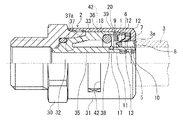
図7に示すように、本実施形態における継手本体2は、継手部30と被覆部31とを有し、この継手部30と被覆部31の内部に筒状インジケータ32、内周Oリング17、外周シール部材(外周Oリング)18、ロックリング12が装着されている。
Subsequently, an embodiment of a one-touch joint equipped with the joint insertion guide of the present invention will be described.
As shown in FIG. 7, the
筒状インジケータ32は、内筒部35とこの内筒部35の奥側から一体に形成される外筒部36とを有する二重筒構造になっており、この構造により、内筒部35と外筒部36との間には接合パイプ3が挿入可能な挿入間隙部37が形成されている。また、筒状インジケータ32は、透明又は半透明の樹脂によって形成される。
The
内周Oリング17は、内筒部35の外周側に形成された装着溝38に装着され、接合パイプ1が挿入間隙部37に挿入されたときにこの接合パイプ1の内周面側をシールする。一方、外周Oリング18は、外筒部36の内周側に形成された装着凹部39に装着され、接合パイプ1が挿入間隙部37に挿入されたときにこの接合パイプ3の外周面側をシールする。
The inner peripheral O-
ロックリング12は、ステンレス鋼等により略環状に形成され、被覆部31内に装着されている。このロックリング12は、内径側に前述した保持爪13を有し、この保持爪13は、所定の傾斜角度に屈曲形成され、接合パイプ3の外周表面側に係止してこの接合パイプ3を抜け止めするようになっている。
The
挿入ガイド本体1を継手本体2に装着する際には、この挿入ガイド本体1は、内筒部35の外周側に継手本体2の開口側から装着され、装着時には、開口側のロックリング12の保持爪13が段部7に係止して継手本体2内の所定位置に仮着される。このため、挿入ガイド本体1は、手作業による装入時の手ごたえや、図示しない取付け治具を用いた場合にもその装入ストロークを確認するだけで継手本体2に対して容易に装着でき、自動化も簡単になっている。
When the
なお、上記の実施形態においては、継手本体2の内部に筒状インジケータ32を別体に設けているが、この筒状インジケータ32は、継手本体1と一体であってもよい。この場合、内筒部35及び外筒部36が継手本体に一体に形成されることになる。
In the above embodiment, the
継手本体2に接合パイプ3を接合する場合には、図7に示すように接合パイプ3をセットし、後端面8に端面3aを当接させながら接合パイプ3を継手本体2内に挿入する。
この挿入により、図8に示すように挿入ガイド本体1が内周Oリング17に差し掛かった場合には、前述のように突出片11の内周径D1が内周Oリング17の外径D2よりも大径であることから、この突出片11が内周Oリング17に接触することが無く、内周Oリング17に対して突出片11を設けない場合と同様に内側アール面15が接触する。このため、接合パイプ3挿入時の最大荷重に影響を与えることが無い。
When joining the joining
When the
また、図9に示すように、挿入ガイド本体1が外周Oリング18に差し掛かると、前述のように突出片11の外周側先端部20がテーパ面部6の延長線上に形成されていることから、この突出片11がテーパ面部6と同じ角度で外周Oリング18に当接してこの外周Oリング18を無理なく変形させる。このため、接合パイプ3挿入時の最大荷重に影響を与えることが防いで無理なく接合することができる。
Further, as shown in FIG. 9, when the insertion guide
このとき、挿入ガイド本体1の突出片11の先端側には切欠部23が切欠き形成されているが、この切欠部23の長さLが外周側において先端アール面9の位置まで差し掛かることが無く、また、内周側において内周アール面15に差し掛かることが無い大きさに形成されているので、この切欠部23が挿入ガイド本体1に接触して接合パイプ3挿入時の荷重に影響を与えたり、内周Oリング17、外周Oリング18に接触してこれらを傷付けたりするおそれもない。
At this time, a
しかも、樹脂成形時において、挿入ガイド本体1を図示しない樹脂成形型の湯道から切欠部23の位置で切り離す際には、図1(a)に示すように、バリ26が切欠部23の形成される空間内に納まり、このバリ26を切欠部23の長さLよりも短く切断することで、内周Oリング17、外周Oリング18を傷付けることがない。すなわち、前述したように内周径D1を外径D2よりも大径に設け、外周側先端部20をテーパ面部6の延長線上に形成した突出片11に対して切欠部23を設けているので、挿入ガイド本体1が内周Oリング17を乗り越える際にはこの内周Oリング17に切欠部23が触れることが無く、また、外周Oリング18を乗り越える際には、切欠部23を形成した部位が突出片11の形成されていない先端アール面9とほぼ同形状となるため、切欠部23が内周Oリング17、外周Oリング18に引っ掛かることがない。このため、挿入荷重への影響を抑えることができる。
また、このバリ26は、切断後に切欠部23から突出しないため、図10の比較例に示したガイドリング体40のように先端側にバリ部41が形成されることがなく、このバリ部41のように内周Oリング17、外周Oリング18に噛み込まれるおそれが無い。
Moreover, when the
Further, since the
続いて、更に継手本体2に接合パイプ3を挿入すると、挿入ガイド本体1は内周Oリング17、外周Oリング18を乗越え、やがて、挿入間隙部37の奥部37aに突き当る。この際、前述したように突出片11が円弧状になっていることで強度が増して変形しにくくなっているため、挿入ガイド本体1は、奥部37aに対してその位置が確実に決まった状態で装着される。
Subsequently, when the joining
接合パイプ3の接続完了時には、この接合パイプ3の後端部付近が継手本体2に貫通形成した確認窓42より、透明又は半透明の筒状インジケータ32を介して正確に視認することができ、接合パイプ3を確実に所定の挿入位置まで挿入できる。
When the connection of the
1 挿入ガイド本体
2 継手本体
3 接合パイプ
6 テーパ面部
11 突出片
17 内周Oリング(内周シール部材)
20 外周側先端部
21 パーツフィーダ
22 レール
23 切欠部
35 内筒部
38 装着溝
D1 内周径
D2 外径
DESCRIPTION OF
20 Outer
Claims (10)
Priority Applications (1)
| Application Number | Priority Date | Filing Date | Title |
|---|---|---|---|
| JP2008169745A JP5270982B2 (en) | 2008-06-30 | 2008-06-30 | Automatic supply method of push-in fitting and insertion guide |
Applications Claiming Priority (1)
| Application Number | Priority Date | Filing Date | Title |
|---|---|---|---|
| JP2008169745A JP5270982B2 (en) | 2008-06-30 | 2008-06-30 | Automatic supply method of push-in fitting and insertion guide |
Publications (2)
| Publication Number | Publication Date |
|---|---|
| JP2010007803A true JP2010007803A (en) | 2010-01-14 |
| JP5270982B2 JP5270982B2 (en) | 2013-08-21 |
Family
ID=41588537
Family Applications (1)
| Application Number | Title | Priority Date | Filing Date |
|---|---|---|---|
| JP2008169745A Active JP5270982B2 (en) | 2008-06-30 | 2008-06-30 | Automatic supply method of push-in fitting and insertion guide |
Country Status (1)
| Country | Link |
|---|---|
| JP (1) | JP5270982B2 (en) |
Citations (4)
| Publication number | Priority date | Publication date | Assignee | Title |
|---|---|---|---|---|
| JP2003314775A (en) * | 2002-04-19 | 2003-11-06 | Jfe Pipe Fitting Mfg Co Ltd | Insertion type pipe joint and method of inserting pipe into insertion type pipe joint |
| JP2006266326A (en) * | 2005-03-22 | 2006-10-05 | Hitachi Metals Ltd | Pipe joint |
| JP2008025819A (en) * | 2006-07-24 | 2008-02-07 | Sanyo Seisakusho:Kk | Joint |
| JP2010002022A (en) * | 2008-06-23 | 2010-01-07 | Kitz Corp | Easy release joint for resin tube |
-
2008
- 2008-06-30 JP JP2008169745A patent/JP5270982B2/en active Active
Patent Citations (4)
| Publication number | Priority date | Publication date | Assignee | Title |
|---|---|---|---|---|
| JP2003314775A (en) * | 2002-04-19 | 2003-11-06 | Jfe Pipe Fitting Mfg Co Ltd | Insertion type pipe joint and method of inserting pipe into insertion type pipe joint |
| JP2006266326A (en) * | 2005-03-22 | 2006-10-05 | Hitachi Metals Ltd | Pipe joint |
| JP2008025819A (en) * | 2006-07-24 | 2008-02-07 | Sanyo Seisakusho:Kk | Joint |
| JP2010002022A (en) * | 2008-06-23 | 2010-01-07 | Kitz Corp | Easy release joint for resin tube |
Also Published As
| Publication number | Publication date |
|---|---|
| JP5270982B2 (en) | 2013-08-21 |
Similar Documents
| Publication | Publication Date | Title |
|---|---|---|
| EP2392845B1 (en) | Pipe joint | |
| JP2009513886A (en) | Plug fitting | |
| KR101434767B1 (en) | Device for Connecting a Plastic Tube to a Connection Nipple | |
| AU2010261529B2 (en) | Push-fit pipe fitting system with support sleeve | |
| KR102447847B1 (en) | Pipe coupler and coupling methods | |
| JP4947706B2 (en) | Pipe fitting | |
| JP5270982B2 (en) | Automatic supply method of push-in fitting and insertion guide | |
| JP2011163474A (en) | Pipe joint | |
| JP5400367B2 (en) | Electric fusion joint | |
| JP6177650B2 (en) | Connecting device | |
| JP2011117563A (en) | Electric fusion joint | |
| JP2006097879A (en) | Pipe joint | |
| TWM545859U (en) | Quick connector of oil pipe with pipeline position confirmation | |
| US20180245722A1 (en) | System, method and apparatus for expansion coupling for pipes with sheathed grooves | |
| JP2010065769A (en) | Pipe joint | |
| JP2009144755A (en) | Pipe joint with anti-rotation function | |
| US20180087703A1 (en) | Sanitary tee or wye fitting component and use in a dwv system | |
| JP2011080522A (en) | Pipe joint | |
| JP2009138869A (en) | Pipe joint connection component and piping structure | |
| KR101358520B1 (en) | Male joint member for pipe joint | |
| CN208927751U (en) | Connection structure and water treatment facilities of integrated water route board and pipeline | |
| JP2021055763A (en) | Joint | |
| TWI803552B (en) | Centering Mechanism for Piping of Butterfly Valve | |
| KR20170003104U (en) | Sewer drainage canal | |
| JP2011106671A (en) | Pipe joint |
Legal Events
| Date | Code | Title | Description |
|---|---|---|---|
| A621 | Written request for application examination |
Free format text: JAPANESE INTERMEDIATE CODE: A621 Effective date: 20110622 |
|
| A977 | Report on retrieval |
Free format text: JAPANESE INTERMEDIATE CODE: A971007 Effective date: 20130110 |
|
| A131 | Notification of reasons for refusal |
Free format text: JAPANESE INTERMEDIATE CODE: A131 Effective date: 20130115 |
|
| A521 | Request for written amendment filed |
Free format text: JAPANESE INTERMEDIATE CODE: A523 Effective date: 20130318 |
|
| TRDD | Decision of grant or rejection written | ||
| A01 | Written decision to grant a patent or to grant a registration (utility model) |
Free format text: JAPANESE INTERMEDIATE CODE: A01 Effective date: 20130416 |
|
| A61 | First payment of annual fees (during grant procedure) |
Free format text: JAPANESE INTERMEDIATE CODE: A61 Effective date: 20130510 |
|
| R150 | Certificate of patent or registration of utility model |
Free format text: JAPANESE INTERMEDIATE CODE: R150 Ref document number: 5270982 Country of ref document: JP Free format text: JAPANESE INTERMEDIATE CODE: R150 |
|
| R250 | Receipt of annual fees |
Free format text: JAPANESE INTERMEDIATE CODE: R250 |
|
| R250 | Receipt of annual fees |
Free format text: JAPANESE INTERMEDIATE CODE: R250 |
|
| R250 | Receipt of annual fees |
Free format text: JAPANESE INTERMEDIATE CODE: R250 |
|
| R250 | Receipt of annual fees |
Free format text: JAPANESE INTERMEDIATE CODE: R250 |
|
| R250 | Receipt of annual fees |
Free format text: JAPANESE INTERMEDIATE CODE: R250 |
|
| R250 | Receipt of annual fees |
Free format text: JAPANESE INTERMEDIATE CODE: R250 |
|
| R250 | Receipt of annual fees |
Free format text: JAPANESE INTERMEDIATE CODE: R250 |
|
| R250 | Receipt of annual fees |
Free format text: JAPANESE INTERMEDIATE CODE: R250 |
|
| S531 | Written request for registration of change of domicile |
Free format text: JAPANESE INTERMEDIATE CODE: R313531 |
|
| R350 | Written notification of registration of transfer |
Free format text: JAPANESE INTERMEDIATE CODE: R350 |
|
| R250 | Receipt of annual fees |
Free format text: JAPANESE INTERMEDIATE CODE: R250 |