JP2010006480A - Paper folding device, paper conveying device, paper post-treatment device, and image forming device - Google Patents
Paper folding device, paper conveying device, paper post-treatment device, and image forming device Download PDFInfo
- Publication number
- JP2010006480A JP2010006480A JP2008164344A JP2008164344A JP2010006480A JP 2010006480 A JP2010006480 A JP 2010006480A JP 2008164344 A JP2008164344 A JP 2008164344A JP 2008164344 A JP2008164344 A JP 2008164344A JP 2010006480 A JP2010006480 A JP 2010006480A
- Authority
- JP
- Japan
- Prior art keywords
- folding
- sheet
- bundle
- roller
- paper
- Prior art date
- Legal status (The legal status is an assumption and is not a legal conclusion. Google has not performed a legal analysis and makes no representation as to the accuracy of the status listed.)
- Granted
Links
Images


Abstract
Description
本発明は、複写機、プリンタ、印刷機などの画像形成装置に一体に組み込まれる用紙折り装置と画像形成装置、および画像形成装置用に別体に設けられ、用紙折り装置等が組み込まれていて画像形成済みの用紙(記録媒体)に対して所定の処理を行って排紙する用紙搬送装置や用紙後処理装置、更にはこれら別体装置と画像形成装置本体とからなる画像形成装置(システム)に関する。 The present invention provides a sheet folding apparatus and an image forming apparatus that are integrated into an image forming apparatus such as a copying machine, a printer, and a printing machine, and a separate unit for the image forming apparatus. An image forming apparatus (system) comprising a sheet conveying apparatus and a sheet post-processing apparatus for performing a predetermined process on a sheet (recording medium) on which an image has been formed and discharging the sheet, and further comprising the separate apparatus and the image forming apparatus main body. About.
画像形成装置本体の下流側へ別体補助装置として配置されて、出力されてくる記録紙などに綴じ加工や折り加工などを施す後処理装置が広く知られている。こうした後処理装置は、昨今その機能は多機能化され、従来からの端面綴じ処理に加えて中綴じ処理も一般化し、また、アウトプット品質の向上手段として中綴じ折り処理された冊子の折り品質の向上手段が提案されている。しかし、それらの多くは機械が大きくなったり、あるいは複合化したために機能に制約が生じている。なお、画像形成装置自体に後処理機構を組み込む場合もあるが、この場合にも上記の事情は同様である。
従来の別体装置の例として、例えば、特許文献1においては、外付け装置として、一対の折りローラと突き出し板により折り目をつけた後、下流に軸を所定角度傾けて配置した加圧ローラにより増し折り処理を行なうようにした折り装置が提案されている。これは、折り部に対し局所的に加圧を行ない、単位長さあたりの押圧力を大きくして、折り品質の向上を計ったものである。
しかし、この構成では確かに折り品質の向上が見込めるが、高価な加圧ローラが新たに必要となってしまい、かつ加圧ローラと増し折りローラの両者に跨って搬送される場合、ローラ部毎で用紙搬送方向が一致しない(僅かに交差する)ため、どちらかのローラに対して用紙のスリップが生じているので、画像面の汚れ、最悪の場合には用紙の破れ等が生じ、アウトプット品質に重大な影響を与える可能性がある。
この問題を解消する方法として、上流側の加圧ローラのニップを抜けてから、下流側のローラにて加圧するように、加圧ローラ間の距離を離して配置する方法が考えられるが、スペースを必要とし、さらにコストアップとなり大型化になり易い欠点がある。もう一つの手段としては、下流の加圧ローラに挟まれる前に、上流側の加圧ローラのニップを解除し、搬送力伝達を無くす方法が考えられるが、複雑な機構が必要となり、かつ受け渡し時の用紙搬送タイミングの設定が難しく、搬送信頼性が低下しがちで、コストも増す。
2. Description of the Related Art A post-processing device that is disposed as a separate auxiliary device downstream of an image forming apparatus main body and performs binding processing or folding processing on output recording paper or the like is widely known. These post-processing devices have recently been multi-functionalized and generalized the saddle-stitching process in addition to the conventional edge-stitching process, and the folding quality of booklets that have been saddle-stitched as an output quality improvement means. The improvement means of this is proposed. However, many of them are limited in function because the machine is large or complex. Note that the post-processing mechanism may be incorporated in the image forming apparatus itself, but the above situation is the same in this case.
As an example of a conventional separate device, for example, in
However, with this configuration, it is possible to improve the folding quality. However, if an expensive pressure roller is newly required and transported across both the pressure roller and the additional folding roller, each roller section In this case, the paper transport direction does not match (slightly intersects), so the paper slips with respect to either roller, so that the image surface is soiled, and in the worst case, the paper is torn. May have a significant impact on quality.
As a method for solving this problem, a method in which the distance between the pressure rollers is arranged so as to be pressed by the downstream roller after passing through the nip of the upstream pressure roller is considered. Is required, which further increases costs and tends to increase in size. Another method is to release the nip of the upstream pressure roller before it is sandwiched by the downstream pressure roller to eliminate the transfer of the conveying force. However, a complicated mechanism is required and delivery is performed. It is difficult to set the paper conveyance timing at the time, the conveyance reliability tends to be lowered, and the cost increases.
他の例として、特許文献2においては、折り目に対し熱及び圧力を加える手段を設けることにより、折り品質を向上させるものが提案されているが、これは電力を消費するばかりでなく、加熱ローラ、温度を制御するための制御手段等が必要となってしまい、高コストとなる難点がある。この他、特許文献3あるいは特許文献4においては、一対の折りローラを正逆回転させることにより、複数回折り処理を行ない、枚数が多くなるに従い、往復折りの回数を増加させるようにするものが提案されている。しかしながら、回数が増加するに従い、処理時間が増し、生産性が低下してしまう不具合がある。
また、特許文献5においては、増し折りローラを用紙搬送方向に対して直交する方向に移動させ、折り部に局所的に加圧することにより増し折り効果を狙ったものが提案されている。しかしながら、増し折りローラの往復移動時には、用紙束を停止させていなければならず、生産性が劣る。
この他、本出願人により中折り処理機構を包含し構成された用紙処理装置が、出願されている(特許文献6)。この特許文献6の開示装置では、端面綴じスティプラと中綴じスティプラが同一の用紙処理トレイの下端と略中央部に設けられている。端面綴じスティプラは、正逆転可能なスティプラ移動モータによりタイミングベルトを介して駆動され、用紙端部の所定位置を綴じるために用紙幅方向に移動する。その移動範囲の一側端には、端面綴じスティプラのホームポジションを検出するスティプラ移動HPセンサが設けられており、用紙幅方向の綴じ位置は、前記ホームポジションからの端面綴じスティプラ移動量により制御される。そして、綴じられた用紙束は、中折り処理トレイ側に搬送され、中折りされる。
Japanese Patent Application Laid-Open No. 2004-228561 proposes a paper that aims at an additional folding effect by moving the additional folding roller in a direction orthogonal to the sheet conveying direction and locally pressing the folding unit. However, when the additional folding roller is reciprocated, the sheet bundle must be stopped, resulting in poor productivity.
In addition to this, a paper processing apparatus including a half-fold processing mechanism has been filed by the present applicant (Patent Document 6). In the device disclosed in Patent Document 6, an end-face stitching stapler and a saddle stitching stapler are provided at the lower end and substantially the center of the same sheet processing tray. The end-face stitching stapler is driven via a timing belt by a forward / reversely movable stapler moving motor, and moves in the sheet width direction in order to bind a predetermined position of the sheet edge. A stapler movement HP sensor that detects the home position of the end-face stitching stapler is provided at one end of the movement range, and the binding position in the sheet width direction is controlled by the amount of end-face stitching stapler movement from the home position. The Then, the bound sheet bundle is conveyed to the middle folding processing tray side and folded in half.
本発明は、従来技術に見られた上記した難点に鑑み創案されたもので、コンパクトかつ低コストで、処理時間が短く、高アウトプット品質で、信頼性も高い、改良された中折り手段を有した用紙搬送装置、用紙後処理および画像処理装置を提供することを目的とする。 The present invention has been devised in view of the above-mentioned difficulties found in the prior art, and is an improved half-folding means that is compact and low-cost, has a short processing time, high output quality, and high reliability. It is an object of the present invention to provide a sheet transport device, a sheet post-processing device, and an image processing device that are provided.
上記の課題を解決するために、請求項1に記載の発明の用紙折り装置は、対となり用紙束に折りを施すためのニップを形成している折りローラと、前記折りローラのニップに用紙束を折り線部位を先頭にして送り込むための折プレートと、前記折りローラで折られた用紙束を、その折り部が折りローラのニップ部より上流方向に抜ける位置まで逆搬送する逆搬送手段と、逆搬送後に前記用紙束を前記ニップに再進入させる再搬送手段と、を備え、制御手段が、前記折り部を前記折りローラに対し傾けた状態に姿勢変更して前記ニップに再進入させることを特徴とする。
また、請求項2に記載の発明の用紙折り装置は、請求項1に記載の用紙折り装置において、前記ニップ部の上流側位置に前記用紙束搬送方向と直交方向に離間して配置され、前記逆搬送手段兼再搬送手段を構成する1組のスイッチバックローラを備え、前記スイッチバックローラのそれぞれの回転方向の異同または搬送量の差を前記制御手段で制御することによって、前記用紙束の上記姿勢変更並びに斜め再搬送を行なうことを特徴とする。
また、請求項3に記載の発明の用紙折り装置は、請求項1または2に記載の用紙折り装置において、前記制御手段が、折り枚数情報取得手段からの出力に基づいて、上記姿勢変更時のスキュー量を決定し制御することを特徴とする。
また、請求項4に記載の発明の用紙折り装置は、請求項3に記載の用紙折り装置において、前記制御手段は、折り枚数が増加するに従い、前記スキュー量を大きく設定して姿勢変更制御を行なうことを特徴とする。
また、請求項5に記載の発明は、用紙搬送装置であって、請求項1乃至4の何れか一項に記載の用紙折り装置を有することを特徴とする。
請求項6に記載の発明は、用紙後処理装置であって、請求項1乃至4の何れか一項に記載の用紙折り装置を有することを特徴とする。
請求項7に記載の発明は、画像形成装置であって、請求項1乃至4の何れか一項に記載の用紙折り装置を有することを特徴とする。
また、請求項8に記載の発明の画像形成装置は、請求項5に記載の用紙搬送装置もしくは請求項6に記載の用紙後処理装置を備えることを特徴とする。
In order to solve the above-mentioned problem, a sheet folding device according to
A paper folding device according to a second aspect of the present invention is the paper folding device according to the first aspect, wherein the paper folding device is arranged at an upstream position of the nip portion and spaced apart in a direction orthogonal to the paper bundle conveying direction, A pair of switchback rollers constituting reverse conveying means / reconveying means, and the control means controls the difference in the rotational direction of each of the switchback rollers or the difference in the conveyance amount, whereby The posture is changed and oblique re-conveyance is performed.
According to a third aspect of the present invention, there is provided the paper folding device according to the first or second aspect, wherein the control unit is configured to change the posture based on an output from the folding number information acquisition unit. The skew amount is determined and controlled.
According to a fourth aspect of the present invention, in the paper folding apparatus according to the third aspect, the control means sets the skew amount to be larger and performs posture change control as the number of folded sheets increases. It is characterized by performing.
According to a fifth aspect of the present invention, there is provided a paper conveying apparatus including the paper folding apparatus according to any one of the first to fourth aspects.
A sixth aspect of the present invention is a paper post-processing apparatus having the paper folding device according to any one of the first to fourth aspects.
A seventh aspect of the present invention is an image forming apparatus having the sheet folding device according to any one of the first to fourth aspects.
According to an eighth aspect of the present invention, there is provided an image forming apparatus comprising the paper conveying apparatus according to the fifth aspect or the paper post-processing apparatus according to the sixth aspect.
本発明によれば、コンパクトかつ低コストで、処理時間が短く、高アウトプット品質で、信頼性も高い、折り特性が改良された中折り装置、これを有した用紙搬送装置、用紙後処理装置および画像処理装置を提供することができる。本発明では、用紙搬送装置等で中折り装置を構成している折りローラにて折り目をつけ、用紙束をスイッチバックさせて折り目を折りローラに対して傾けた状態で、折りローラに再度進入させることで、増し折りを行ない、さらに中折り枚数に応じて、折りローラに対する折り目の傾き量を可変としている。この構成を備えることによって、処理時間が短く、また、中折りと増し折りを同一の折りローラで行なうことで、コンパクトかつ低コスト、折り部を斜めに搬送することで折り部に対し局所的に加圧して、単位長さあたりの押圧力を大きくすることで、高アウトプット品質で、信頼性も高い中折り処理が可能な中折り装置等が提供される。 According to the present invention, a compact and low-cost, short processing time, high output quality, high reliability, and a folding device with improved folding characteristics, a paper transport device having the same, and a paper post-processing device In addition, an image processing apparatus can be provided. In the present invention, a crease is formed by a folding roller constituting a half-folding device such as a paper conveying device, the paper bundle is switched back, and the fold is inclined with respect to the folding roller and reenters the folding roller. Thus, additional folding is performed, and the amount of fold inclination with respect to the folding roller is variable according to the number of intermediate folds. By providing this configuration, the processing time is short, and by performing the middle folding and additional folding with the same folding roller, it is compact and low-cost, and the folding section is conveyed diagonally so that it can be locally applied to the folding section. By applying pressure and increasing the pressing force per unit length, a folding device or the like capable of performing folding processing with high output quality and high reliability is provided.
以下、図面を参照して、本発明の実施形態を詳細に説明する。
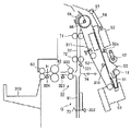
図1は本発明の実施形態に係る用紙処理装置としてのシート処理装置としての用紙後処理装置と画像形成装置(本体部)とからなる画像形成システムのシステム構成を示す図であり、この図では、用紙後処理装置の全体と画像形成装置本体の一部が示されている。
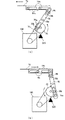
また、図2は、本実施形態の特徴部である中折り機構(中折り処理装置)の主要部について概略構成を示した拡大横断面図である。
この実施形態においては、画像形成装置(本体部)は、既知の各種知られた構成のどのようなもので良く、印字方式も問わない。要は後で詳述する用紙後処理装置に対して、画像形成済みの個々単葉の用紙を順に送り込むように構成されていれば足りる。従って明細書中では、詳しい説明はしない。
一方、実施形態に示した用紙後処理装置は、今回特徴部を含むが、全体構成としては類似構成の用紙後処理装置が、本出願人により既に出願され公開されている(特許文献6)。そして、本明細書中および添付の図面中での符号は、特許文献6に開示の装置(以下では、既出願装置と記すことにする)と同等部分には同一の符号を付すようにした。
従って、本明細書中では、発明を明瞭にする意図もあり、上記既出願装置と同一構成部分で本願発明に直接の関連が薄い部分については、特許文献6と重複する説明を省略あるいは簡略化してある。
Hereinafter, embodiments of the present invention will be described in detail with reference to the drawings.
FIG. 1 is a diagram showing a system configuration of an image forming system including a sheet post-processing apparatus as a sheet processing apparatus and an image forming apparatus (main body) as a sheet processing apparatus according to an embodiment of the present invention. The entire sheet post-processing apparatus and a part of the image forming apparatus main body are shown.
FIG. 2 is an enlarged cross-sectional view showing a schematic configuration of a main part of a center folding mechanism (a center folding processing apparatus) which is a characteristic part of the present embodiment.
In this embodiment, the image forming apparatus (main body unit) may be any of various known configurations, and the printing method is not limited. In short, it suffices if it is configured to sequentially feed individual single-sheet sheets on which images have been formed to a sheet post-processing apparatus described in detail later. Therefore, detailed description will not be given in the specification.
On the other hand, although the sheet post-processing apparatus shown in the embodiment includes a feature part this time, a paper post-processing apparatus having a similar configuration as an overall configuration has already been filed and published by the present applicant (Patent Document 6). In the present specification and the accompanying drawings, the same reference numerals are given to the same parts as those of the device disclosed in Patent Document 6 (hereinafter referred to as an already-applied device).
Accordingly, in the present specification, there is also an intention to clarify the invention, and a description overlapping with that of Patent Document 6 is omitted or simplified for a portion that is the same as the above-mentioned already-applied apparatus and is not directly related to the present invention. It is.
以下、用紙後処理装置の概略説明をする。図1において、用紙後処理装置PDは、画像形成装置PRの側部に取り付けられており、画像形成装置PRから排出されたシート状記録媒体(以下、単に用紙と称する)が用紙後処理装置PDに導かれる。
前記用紙は、1枚毎の用紙に後処理を施す後処理手段(この実施形態では穿孔手段としてのパンチユニット100)を有する搬送路Aを通り、上トレイ201へ導く搬送路B、シフトトレイ202へ導く搬送路C、整合及びスティプル綴じ等を行なう処理トレイFへ導く搬送路Dへ、それぞれ分岐爪15及び分岐爪16によって振り分けられるように構成されている。
なお、画像形成装置PRは、既に周知であるから図1では全く図示されていない機能部群、すなわち、入力される画像データを印字可能な画像データに変換する画像処理回路、画像処理回路から出力される画像信号に基づいて感光体に光書き込みを行なう光書き込み装置、光書き込みにより感光体に形成された潜像をトナー現像する現像装置、現像装置によって顕像化されたトナー像を用紙に転写する転写装置、及び用紙転写されたトナー像を定着する定着装置を少なくとも備え構成されている。
前記画像処理回路、光書き込み装置、現像装置、転写装置、及び定着装置とが画像形成手段を構成している。この、画像形成装置PRにおいてトナー画像が定着された画像形成済み用紙を用紙後処理装置PDに送り出し、用紙後処理装置PDによって所望の後処理が行われる。画像形成装置PRはここでは前述のように電子写真方式のものであるが、インクジェット方式、熱転写方式などの公知の画像形成装置が全て使用できる。
The outline of the sheet post-processing apparatus will be described below. In FIG. 1, a sheet post-processing apparatus PD is attached to a side portion of the image forming apparatus PR, and a sheet-like recording medium (hereinafter simply referred to as a sheet) discharged from the image forming apparatus PR is a sheet post-processing apparatus PD. Led to.
The sheet passes through a conveyance path A having post-processing means (in this embodiment,
Note that the image forming apparatus PR is already well known and is not shown in FIG. 1 at all, that is, an image processing circuit that converts input image data into printable image data, and an output from the image processing circuit. Optical writing device that performs optical writing on the photoconductor based on the image signal generated, a developing device that develops the latent image formed on the photoconductor by optical writing, and a toner image that is visualized by the developing device is transferred to the paper And a fixing device for fixing the toner image transferred on the paper.
The image processing circuit, the optical writing device, the developing device, the transfer device, and the fixing device constitute an image forming unit. The image-formed paper on which the toner image is fixed in the image forming apparatus PR is sent to the paper post-processing device PD, and desired post-processing is performed by the paper post-processing device PD. Here, the image forming apparatus PR is of an electrophotographic system as described above, but any known image forming apparatus such as an ink jet system or a thermal transfer system can be used.
用紙は、搬送路A及びDを経て端面綴じ処理トレイFへ導かれ、この端面綴じ処理トレイFで整合及びスティプル等を施される。次に偏向手段である分岐ガイド板54と可動ガイド55により、シフトトレイ202へ導く搬送路C、折り等を施す中折り処理トレイGへ振り分けられる。中折り処理トレイGで折り等を施された用紙は搬送路Hを通り下トレイ203へ導かれる。
また、搬送路D内には分岐爪17が配置され、図示しない低荷重バネにより図の状態に保持されており、用紙後端がこれを通過した後、搬送ローラ9、10、スティプル排紙ローラ11の内少なくとも搬送ローラ9を逆転することで後端を用紙収容部Eへ導いて滞留させ、次用紙と重ね合せて搬送することが可能なように構成されている。この動作を繰り返すことによって2枚以上の用紙を重ね合せて束として搬送することも可能である。
搬送路B、搬送路C及び搬送路Dの上流で各々に対し共通な搬送路Aには、画像形成装置PRから受け入れる用紙を検出する入口センサ301、その下流に入口ローラ1、パンチユニット100、パンチかすホッパ101、搬送ローラ2、分岐爪15及び分岐爪16が順次配置されている。分岐爪15、分岐爪16は図示しないバネにより図1の状態に保持されており、図示しないソレノイドをONすることにより、分岐爪15は上方に、分岐爪16は下方に、各々回動し、回動状態の組み合わせによって、搬送路B、搬送路C、搬送路Dへ用紙を振り分ける。
この用紙後処理装置では、用紙に対して、穴明け(パンチユニット100)、用紙揃え+端部綴じ(ジョガーフェンス53、端面綴じスティプラS1)、用紙揃え、用紙の仕分け(シフトトレイ202)、中綴じ等の処理及び本願発明の特徴部である用紙折り装置により実行される中折り処理(折りプレート74、搬送ローラ81、搬送ローラ82、折りローラ82による)などの各処理を行なうことができる。
The sheet is guided to the end surface binding processing tray F through the transport paths A and D, and alignment and stapling are performed on the end surface binding processing tray F. Next, by a
Further, a branching claw 17 is disposed in the conveyance path D, and is held in the state shown in the figure by a low load spring (not shown). After the trailing edge of the sheet passes through this, the conveyance rollers 9, 10 and the
In the conveyance path A common to the upstream of the conveyance path B, the conveyance path C, and the conveyance path D, an
In this paper post-processing apparatus, punching (punching unit 100), paper alignment + edge binding (
図1に示されている、2.)シフトトレイ部、2.1)シフトトレイの昇降機構、2.2)排紙部、3.)端面綴じ処理トレイ、3.2)用紙放出機構、3.3)処理機構、4.)用紙束偏向機構についての詳細構成と動作は、本願発明と直接の関連は無く、しかも、特許文献6では、詳細に説明されている[特許文献6では、1.1)全体構成、に続いて図1相当の各部について説明されている]ため本明細書での説明は省略する。
この実施形態では、スティプル処理トレイFと中折り処理トレイGは放出ローラ56の表面の円弧を屈曲部として中折り処理トレイG側が垂直に、スティプル処理トレイF側が急角度で傾斜した状態に配置され、一体化されている。スティプル処理トレイFの傾斜角は小さい方が垂直投影面積が小さくなり、ひいては占有床面積が小さくなるので望ましい。
しかし、この実施形態では、図4に示した折り機構、すなわち、折りプレート74、リンクアーム76、折りプレート駆動カム75及び折りプレート駆動モータ166を、中折り処理トレイG(束搬送ガイド板下上91、92)とスティプル処理トレイFの間の空間に設ける。その際、これらの折り機構を、端面綴じスティプラS1と中綴じスティプラS2の間に位置させてある。
As shown in FIG. 2.) Shift tray section, 2.1) Shift tray lifting mechanism, 2.2) Paper discharge section, ) End face binding processing tray, 3.2) Paper discharge mechanism, 3.3) Processing mechanism, The detailed configuration and operation of the sheet bundle deflecting mechanism are not directly related to the present invention, and are described in detail in Patent Document 6 [1.1 in Patent Document 6] Following the overall configuration. Therefore, the description in this specification is omitted.
In this embodiment, the staple processing tray F and the middle folding processing tray G are arranged in a state where the middle folding processing tray G side is vertically inclined and the staple processing tray F side is inclined at a steep angle with the arc of the surface of the
However, in this embodiment, the folding mechanism shown in FIG. 4, that is, the
中折りする場合には、後述する折りプレートによって折る位置に用紙束の中央部を位置させる必要がある。そのため、本実施形態では、束搬送ガイド板下91に可動後端フェンス73を設け、この可動後端フェンス73に用紙束の後端(折り処理後後端、搬送時には先端になる)を当接させ、この当接した状態で上下方向に移動させて折り位置に用紙束の中心が位置するように制御している。
この可動後端フェンス73は、駆動プーリ73aと従動プーリ73bとの間に張設された駆動ベルト73cに固定され、図示しない後端フェンス移動モータによって上下方向に駆動される。これらの可動後端フェンス73の駆動機構は、前述の折り機構と同様に、スティプル処理トレイFと中折り処理トレイGとの間の空間に配置され、垂直投影面積が増加しないように配慮されている。
各処理部によって順にあるいは協働して適宜処理され整列され、必要に応じて綴じ処理された用紙束(場合によっては単用紙)の中折りはスティプル処理トレイFの下流側に設けられた中折り処理トレイGにおいて行われる。中綴じされた用紙束はスティプル処理トレイFから用紙束偏向機構により中折り処理トレイGに導かれる。
In the case of half-folding, it is necessary to position the central portion of the sheet bundle at a position where folding is performed by a folding plate described later. Therefore, in this embodiment, a movable
The movable
A half-fold provided on the downstream side of the staple processing tray F is a half-fold of a sheet bundle (in some cases, a single sheet) that is appropriately processed and aligned by each processing unit in order or in cooperation. This is performed in the processing tray G. The saddle stitched sheet bundle is guided from the staple processing tray F to the center folding processing tray G by the sheet bundle deflection mechanism.
以下、中折り処理トレイGの構成について説明する。
5.1)中折り処理トレイの構成
図1および図2に示すように分岐ガイド板54と可動ガイド55とからなる用紙束偏向機構の下流側に中折り処理トレイGが設けられている。中折り処理トレイGは、前記用紙束偏向機構の下流側にほぼ垂直姿勢に設けられており、中央部に中折り機構が、その上方に束搬送ガイド板上92が、また、下方に束搬送ガイド板下91が配置されている。また、束搬送ガイド板上92の上部には束搬送ローラ上71が、下部には束搬送ローラ下72がそれぞれ設けられている。
また、束搬送ガイド板下91を横切るように可動後端フェンス73が配置され、タイミングベルト73aとその駆動機構とを備えた移動機構により用紙搬送方向(図において上下方向)に移動可能となっている。駆動機構は、図1に示されているように前記タイミングベルト73aが掛け渡された駆動プーリ73bと従動プーリ73cと、駆動プーリ73bを駆動するステッピングモータ73dとにより構成されている。
Hereinafter, the configuration of the half-fold processing tray G will be described.
5.1) Configuration of the middle folding processing tray As shown in FIGS. 1 and 2, the middle folding processing tray G is provided on the downstream side of the sheet bundle deflection mechanism including the
A movable
次に、本実施形態の特徴部である中折り機構について詳述する。図2に拡大して示されている中折り機構は、中折り処理トレイGのほぼ中央部に設けられ、折りプレート74と、用紙(束)の逆搬送手段と再搬送手段を兼ねている束搬送手段81(上下対の束搬送ローラ503を含み構成されている)、および折りローラ82(上下対)と、用紙束を搬送する搬送路Hとからなっている。なお、搬送路Hの下流側には、後搬送ローラ83(下排紙ローラ)が配設してある。
折りローラ(対)82は、図示しないスプリング等の加圧手段により、加圧されている。折りローラ82の上流側に位置して配置されている束搬送手段81は、用紙束を搬送するための束搬送ローラ503(上下対)や駆動モータ500を含み構成されて駆動制御部(図示なし)と協働し、用紙束を逆搬送し姿勢変更し再搬送する。束搬送手段81と折りローラ82との間に、折り部通過センサ323が設けてある。
Next, the folding mechanism that is a characteristic part of the present embodiment will be described in detail. The center folding mechanism shown in an enlarged manner in FIG. 2 is provided at substantially the center of the center folding processing tray G, and serves as a
The folding roller (pair) 82 is pressed by a pressing means such as a spring (not shown). The
図3に、束搬送手段81の機構部を示す。図3(a)は、上方から見た配置図(b)は、側面図(503a側)である。なお、図3(c)に、束搬送手段81近傍での配置を示した。この束搬送手段81は、用紙搬送中心に対して左右略対称に2組設けられている。
それぞれの束搬送手段81において、上下一対の束搬送ローラのうちの下側の束搬送ローラ503は、図3に示すようにタイミングプーリ502、タイミングベルト501を介し、左右で個々に設けられた駆動モータ500に連結され、駆動モータの回転に従い、正逆方向に回転可能に構成されている。
各束搬送手段は、それぞれ独立して制御されて束搬送ローラ503が左右独立して回転し、それぞれの用紙搬送時の束搬送の回転量を変化させることで、用紙の姿勢を変えることが可能な構成となっている。すなわち、スイッチバックローラのそれぞれの回転方向の異同または搬送量の差を制御手段で制御することにより、用紙束の上記姿勢変更が可能で、また斜め姿勢を保っての搬送も可能である。この束搬送手段81の動作については、後で図6、図7を用いて詳述する。
FIG. 3 shows a mechanism part of the
In each
Each bundle conveying means is independently controlled so that the
5.2)折りプレート及びその作動機構
図4(a)、(b)は中折りを行なうための折りプレート74の移動機構の動作説明図である。折りプレート74は前後側板64a、64bに立てられた各2本の軸64cに長孔部74aを遊嵌することにより支持され、さらに、折りプレート74から立設された軸部74bがリンクアーム76の長孔部76bに遊嵌され、リンクアーム76が支点76aを中心に揺動することにより、折りプレート74は図4(a)、(b)中を左右に往復移動する。すなわち、リンクアーム76の長孔部76cに折りプレート駆動カム75の軸部75bは遊嵌されており、折りプレート駆動カム75の回転運動によりリンクアーム76は揺動し、これに応じて、図2において、折りプレート74は束搬送ガイド板下上91、92に対して垂直な方向に往復動する。
折りプレート駆動カム75は折りプレート駆動モータ166により図4(a)中の矢印方向に回転する。その停止位置は半月形状の遮蔽部75a両端部を折りプレートHPセンサ325により検知することで決定される。
5.2) Folding plate and operating mechanism thereof FIGS. 4A and 4B are operation explanatory views of the moving mechanism of the
The folding
図4(a)は、中折り処理トレイGの用紙束収容領域から完全に退避したホームポジション位置を示す。折りプレート駆動カム75を矢印方向に回転させると折りプレート74は矢印方向に移動し、中折り処理トレイGの用紙束収容領域に突出する。図4(b)は、中折り処理トレイGの用紙束中央を折りローラ82のニップに押し込む位置を示す。折りプレート駆動カム75を矢印方向に回転させると折りプレート74は図4(b)中の矢印方向に移動し、中折り処理トレイGの用紙束収容領域から退避する。
なお、この実施形態では、中折り機能については用紙束を綴じることを前提にしているが、1枚の用紙を折る場合にも使用できる。この場合は、用紙は1枚だけで中綴じが不要なので、1枚排紙された時点で中折り処理トレイG側に送り込み、折りプレート74と折りローラ82とによって折り処理を実行して下トレイ203に排紙するようにする。
FIG. 4A shows the home position completely retracted from the sheet bundle storage area of the half-fold processing tray G. FIG. When the folding
In this embodiment, the folding function is premised on binding a bundle of sheets, but it can also be used when folding a single sheet. In this case, since only one sheet is required and saddle stitching is not necessary, when one sheet is discharged, the sheet is fed to the middle folding processing tray G side, and folding processing is executed by the
6.)制御装置
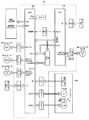
制御装置350は、図5に示すように、特許文献6に開示のもの同等であり、CPU360、I/Oインターフェース370等を有するマイクロコンピュータからなる。CPU360には各種の信号が入力される。すなわち、画像形成装置PR本体のコントロールパネルの各スイッチ等、及び入口センサ301、上排紙センサ302、シフト排紙センサ303、プレスタックセンサ304、スティプル排紙センサ305、紙有無センサ310、放出ベルトホームポジションセンサ311、スティプル移動ホームポジションセンサ312、スティプラ斜めホームポジションセンサ313、ジョガーフェンスホームポジションセンサ314、束分岐ガイドホームポジションセンサ315、束到達センサ321、可動後端フェンスホームポジションセンサ322、折り部通過センサ323、下排紙センサ(折り部通過センサ)324、折りプレートホームポジションセンサ325、紙面検知センサ330、330a、330b、505等の各センサからの信号がI/Oインターフェース370を介してCPU360へと入力される。
6). ) Control Device As shown in FIG. 5, the
CPU360は、入力された信号に基づいて、シフトトレイ202用のトレイ昇降モータ168、開閉ガイド板を開閉する排紙ガイド板開閉モータ167、シフトトレイ202を移動するシフトモータ169、叩きコロ12を駆動する図示しない叩きコロモータ、叩きSOL170等の各ソレノイド、各搬送ローラを駆動する搬送モータ、各排紙ローラを駆動する排紙モータ、放出ベルト52を駆動する放出モータ157、端面綴じスティプラS1を移動するスティプラ移動モータ159、端面綴じスティプラS1を斜めに回転させる斜めモータ160、ジョガーフェンス53を移動するジョガーモータ158、分岐ガイド板54及び可動ガイド55を回動する束分岐駆動モータ161、その束を搬送する搬送ローラを駆動する図示しない束搬送モータ、可動後端フェンス73を移動させる図示しない後端フェンス移動モータ、折りプレート74を移動させる折りプレート駆動モータ166、折りローラ82を駆動する図示しない折りローラ駆動モータ等の駆動を制御する。また、束搬送駆動モータ500(図3参照)の回転方向や回転速度を制御する。
The CPU 360 drives the tray lifting / lowering motor 168 for the
本実施形態に係る用紙後処理装置においては、ユーザにより設定される後処理モードに応じて種々の排出形態をとることが可能である(排出形態個々の詳細については説明省略)。各排出形態、すなわち、(1)ノンスティプルモードA、(2)ノンスティプルモードB、(3)ソート、スタックモード、(4)スティプルモード、(5)中綴じ製本モード等のいずれかに対応して選択的に決まる一連の所定処理が実行された後、続いて必要に応じて用紙折り処理が行われる。
すなわち、指定の排出形態に適合した綴じ処理が終了すると、放出モータが駆動され、放出ベルト52が駆動される。同時に、排紙モータも駆動され、放出爪52aにより持ち上げられた用紙束を受け入れるべくシフト排紙ローラ6が回転し始める。
上記の各動作の制御は前記CPU360によって実行されるが、これら一連の制御は、特許文献6の場合と同等であり、ここでは、個々の詳細説明は略し、以下では、同じくCPU360によって実行される、(5)中綴じ製本モード時の動作についてのみ詳述する。
The paper post-processing apparatus according to the present embodiment can take various discharge forms according to the post-processing mode set by the user (details of the discharge forms are not described). Each discharge mode, ie, (1) non-stipple mode A, (2) non-stipple mode B, (3) sort, stack mode, (4) stipple mode, (5) saddle stitch binding mode, etc. After a series of predetermined processes that are selectively determined according to the above, a sheet folding process is performed as necessary.
That is, when the binding process suitable for the specified discharge form is completed, the discharge motor is driven and the
The control of each of the above operations is executed by the CPU 360, but these series of controls are the same as in the case of Patent Document 6. Here, the detailed description of each operation is omitted, and in the following, it is also executed by the CPU 360. (5) Only the operation in the saddle stitch binding mode will be described in detail.
(5)中綴じ製本モード:
この中綴じ製本モードは、用紙を搬送路Aと搬送路Dを経て端面綴じ処理トレイFに搬送し、スティプル処理トレイFで整合および中央綴じを行った後、さらに中折り処理トレイGで中折りを実行し、中折りされた用紙束を搬送路Hから下トレイ203へ排出するモードである。このモードでは、分岐爪15と分岐爪16はともに反時計方向に回動し、搬送路AからDに至る経路が開放された状態になる。また、分岐ガイド板54と可動ガイド板55が閉鎖状態となって用紙束を中折り処理トレイGに導き、中折りが行われる。なお、中綴じ処理自体は、既知のものと同等であるが、中折り処理が、実施形態特有のもので、改良された中折り処理が実行される。
既存の中綴じ処理について概略説明をする。中綴じ製本モードでは、搬送路Aから分岐爪15と分岐爪16で振り分けられた用紙は、搬送路Dに導かれ、搬送ローラ7、搬送ローラ9、搬送ローラ10を経て、スティプル排紙ローラ11によりスティプル処理トレイFに排出される。スティプル処理トレイFでは(図2参照)、スティプルモード時と同様に排紙ローラ11により順次排出される用紙を整合し、スティプルする直前までは同様の動作をする。
(5) Saddle binding mode:
In this saddle stitch binding mode, the sheet is transported to the end face binding processing tray F through the transport path A and the transport path D, aligned and centered in the staple processing tray F, and then further folded in the center folding processing tray G. This is a mode in which the folded sheet bundle is discharged from the conveyance path H to the
An outline of the existing saddle stitching process will be described. In the saddle stitch binding mode, the paper sorted by the
用紙束が端面綴じ処理トレイFで仮整合された後、放出ベルト52が回転を開始し、用紙束は放出爪52aにより用紙サイズ毎に設定された距離だけ搬送方向下流へ運ばれ、その中央を中綴じスティプラS2により綴じ処理される。綴じられた用紙束は放出爪52aにより搬送方向下流側へ用紙サイズ毎に設定された所定距離搬送され、一旦停止する。この移動距離は放出モータの駆動パルスにより管理される。
その後、用紙束の先端部は放出ローラ56と加圧コロ57により挟持され、分岐ガイド板54と可動ガイド55とが回動することによって形成される経路、すなわち中折り処理トレイGへ導かれる経路を通過するように再度放出爪52aと放出ローラ56により下流へ搬送される。この放出ローラ56は前述のように放出ベルト52の駆動軸に設けられ、放出ベルト52と同期して駆動される。
可動後端フェンス73に突き当てられた用紙束は、束搬送ローラ下72の加圧が解除され、その後、綴じられた針部近傍が折りプレート74により略直角方向に押され、対向する折りローラ81のニップへと導かれる。予め回転している折りローラ81は、ニップに導かれた用紙束を加圧搬送することによって用紙束の中央に折りを施す。
After the sheet bundle is temporarily aligned in the end-face binding processing tray F, the
Thereafter, the leading end portion of the sheet bundle is sandwiched between the
The sheet bundle abutted against the movable
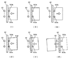
次いで、中折り処理が行われる。図6のフローチャートは中折り装置の動作の流れを示している。以下では、図7の用紙の各工程においての状態を示した(I)〜(VI)の動作説明図を用いて具体的に説明する。
図7における(I)のように折りプレート74及び束搬送ローラ503により用紙束の折り部を先頭にして、折りローラ82方向へ用紙束が搬送される。すなわち、中綴じされた用紙束は束搬送ローラ下72の加圧が解除されたまま、可動後端フェンス73の移動に伴って上方に運ばれ、その後、綴じられた針部近傍を折りプレート74により略直角方向に押し、さらに、進行方向先頭部と対向する折りローラ82のニップへと押し込む。この時、束搬送ローラ503は、離間していて用紙束の進行を妨げない(従動させる、あるいは協働して進行をアシストするよう制御しても良い)。
(II)、予め回転していた折りローラ82は押し込まれてきた用紙束を加圧搬送し、これにより用紙束中央の折り部に折りを施す。このようにして、用紙束への第1回目の中折り動作が行われる。
このようにして折りローラ82で折りを施された用紙束の先頭の折り部が折りローラ82のニップを若干通過した時点で搬送を停止して用紙束をいったん静止させる。この通過時点は、折り部通過センサ323により検知することができる。
Next, the middle folding process is performed. The flowchart of FIG. 6 shows the flow of operation of the half-folding apparatus. Hereinafter, the operation will be specifically described with reference to the operation explanatory diagrams (I) to (VI) showing the state of each step of the sheet of FIG.
As shown in (I) in FIG. 7, the sheet bundle is conveyed toward the
(II) The
When the leading folded portion of the sheet bundle folded by the folding
(III)折りローラ82及び束搬送ローラ503を逆転させ、これにより、用紙束のニップが折りローラ82を抜けた所定距離まで、スイッチバック搬送を行なう。
(IV)次いで、束搬送ローラを互いに逆向き回転となるように回転させることにより、左右1組の束搬送ローラで保持されている用紙束を折りローラ軸線に対し傾けた姿勢に回動する。
(V)前記(IV)の状態で、束搬送ローラを同一方向に同期させて回転し、用紙束を傾けた状態のまま折りローラ82に搬送し折りローラ82により再度折りぐせを強化する増し折り動作を行なう。この時、折り部が斜めの状態で折りローラ82に進入することで、折り部に対し局所的に加圧、単位長さあたりの押圧力を大きくすることが可能になる。
(VI)このようにして折りローラ82で折りぐせを強化された用紙束は折り部が後排紙ローラ83に到達する前に後排紙ローラ83を下トレイ(排紙トレイ)203に向けた排出方向に速度差を持たせ回転させることで姿勢を正され、により下トレイ203上に排出されて順にスタックされる。
このとき、用紙束後端が下排紙センサ(折り部通過センサ)324に検知されると、折りプレート74及び可動後端フェンス73はホームポジションに復帰し、束搬送ローラ下72の加圧力も復帰し、次の用紙に備える。また、次のジョブが同用紙サイズ同枚数であれば、可動後端フェンス73はその位置で待機しても良い。
(III) The
(IV) Next, the bundle conveying rollers are rotated so as to rotate in opposite directions, thereby rotating the sheet bundle held by the left and right bundle conveying rollers to a posture inclined with respect to the folding roller axis.
(V) In the state of (IV), the bundle conveying roller rotates in the same direction in the same direction, and the bundle of sheets is conveyed to the
(VI) The sheet bundle whose folding is strengthened by the folding
At this time, when the rear end of the sheet bundle is detected by the lower paper discharge sensor (folding section passage sensor) 324, the
なお、上述処理におけるスキュー量:θについては、大きくなるほど増し折り効果が高く(折り目に対する単位長さあたりの押圧力が大きくなるため)なる。そこで、実施形態においては、枚数が多くなるに従い、0〜5°に漸増するように設定されている。このために、本実施形態装置では中折り処理に際して、図8のフローチャートに示すように、折り枚数をカウントし、得られた折り枚数に応じて用紙束のスキュー量を決定し、このスキュー量を具現するように制御の際の束搬送ローラの搬送量が変更されて、前述した中折り処理が実行される。以上のように構成された実施形態に係る用紙後処理装置は、意図どおりのコンパクトかつ低コストで、処理時間が短く、高アウトプット品質で、信頼性も高い、折り処理を実現している。
なお、上述した実施形態装置では、姿勢変更の際には左右一対の1組の束搬送ローラ503を互いに逆向きに回転させるように制御しているが、折り目部がスイッチバックし折りローラ82を抜けたタイミングにて片方(左右の対のうち一方)の束搬送ローラの駆動を所定時間停止させた後に残る束搬送ローラ503を停止させるように制御することでも所望の姿勢変更が行なえる。図8のフローチャートから軽微な変更で済むためフローチャートは省略した。あるいは、左右の片方の束搬送ローラ503の駆動を停止させ、もう一方の束搬送ローラ503を所定時間逆転させても同様に用紙束の姿勢制御が可能である。
このように、左右に各1箇所で2つ1組の束搬送ローラ(スイッチバックローラ)503を備えるとともに、これら束搬送ローラ503のそれぞれの回転方向の異同または搬送量の差を制御手段で制御することによって、用紙束の姿勢を変更させることが可能になる。そのまま、斜めに姿勢変更したままで斜め再搬送を行なうこともできる。
As the skew amount θ in the above-described processing increases, the additional folding effect increases (because the pressing force per unit length with respect to the fold increases). Therefore, in the embodiment, it is set to gradually increase to 0 to 5 ° as the number of sheets increases. For this reason, in the embodiment, as shown in the flowchart of FIG. 8, in the middle folding process, the number of folded sheets is counted, the skew amount of the sheet bundle is determined according to the obtained number of folded sheets, and this skew amount is calculated. As described above, the amount of conveyance of the bundle conveyance roller at the time of control is changed, and the above-described half-folding process is executed. The sheet post-processing apparatus according to the embodiment configured as described above realizes folding processing that is compact and low-cost as intended, has a short processing time, has high output quality, and high reliability.
In the above-described embodiment apparatus, when the posture is changed, the pair of left and right
In this way, a set of two bundle conveying rollers (switchback rollers) 503 is provided at one place on each of the left and right sides, and the difference in the rotational direction or the difference in the conveying amount of these
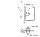
なお、姿勢変更については上述した実施形態のように束搬送ローラ503の駆動を制御する方法以外でも実現できる。例えば、スペース上は不利となるし適宜の搬送手段と併用が必要でありコスト的に不利であるが、図9に示すように上下一対となって用紙を挟持/開放可能で水平回転自在の専用のグリッパ504を設けて、この専用グリッパ504を用紙束をつかんだ状態で回転駆動することで、用紙束を回転させる構成を採用しても用紙束の姿勢制御が可能である。スキュー量は可変にできる。グリッパ504と協働する、挟離自在な搬送ローラ対による定方向搬送用で簡易な再搬送手段(図示なし)等で、スイッチバック動作をさせる。再搬送手段を兼ねて、グリッパ504自体が用紙束搬送方向に水平移動する構成にしてスイッチバック動作を実現しても良い。図9で示す機構にても、前述第1実施形態と同様の折り特性向上効果が得られる。
Note that the posture change can be realized by a method other than the method for controlling the driving of the
6 シフト排紙ローラ、8 プレスタックローラ、32 エンドフェンス、51 後端フェンス、52 放出ベルト、52a 放出爪、53 ジョガーフェンス、54 分岐ガイド板、55 可動ガイド、56 放出ローラ、60 リンクアーム、61 カム、66 支持レール、73 可動後端フェンス、73a タイミングベルト、73b 駆動プーリ、73c 従動プーリ、73d 駆動モータ、74 折りプレート、75 折りプレート駆動カム、76 リンクアーム、81 束搬送手段81、82 折りローラ(上下対)、83 後搬送ローラ(下排紙ローラ)、203 下トレイ(排紙トレイ)、323 折り部通過センサ、324 下排紙センサ(折り部通過センサ)、500 束搬送駆動モータ、501 タイミングベルト、502 タイミングプーリ、503 束搬送ローラ(上下対)、504 グリッパ、F スティプル処理トレイ、G 中折り処理トレイ、PD 用紙後処理装置、PR 画像形成装置、S1 端面綴じスティプラ、S2 中綴じスティプラ 6 shift discharge roller, 8 pre-stack roller, 32 end fence, 51 rear end fence, 52 discharge belt, 52a discharge claw, 53 jogger fence, 54 branch guide plate, 55 movable guide, 56 discharge roller, 60 link arm, 61 Cam, 66 Support rail, 73 Movable rear end fence, 73a Timing belt, 73b Drive pulley, 73c Drive pulley, 73d Drive motor, 74 Fold plate, 75 Fold plate drive cam, 76 Link arm, 81 Bundle conveying means 81, 82 Fold Roller (upper / lower pair), 83 rear transport roller (lower paper discharge roller), 203 lower tray (paper output tray), 323 folding section passage sensor, 324 lower paper ejection sensor (folding section passage sensor), 500 bundle transport driving motor, 501 timing belt, 502 timing Over Li, 503 bundle conveying rollers (upper and lower pair), 504 gripper, F staple processing tray, the processing tray folding in G, PD sheet post-processing apparatus, PR image forming apparatus, S1 end face binding stapler, in S2 stitching stapler
Claims (8)
前記折りローラのニップに用紙束を折り線部位を先頭にして送り込むための折プレートと、
前記折りローラで折られた用紙束を、その折り部が折りローラのニップ部より上流方向に抜ける位置まで逆搬送する逆搬送手段と、
逆搬送後に前記用紙束を前記ニップに再進入させる再搬送手段と、を備え、
制御手段が、前記折り部を前記折りローラに対し傾けた状態に姿勢変更して前記ニップに再進入させることを特徴とする用紙折り装置。 A folding roller forming a nip for folding the bundle of sheets in pairs;
A folding plate for feeding the sheet bundle to the nip of the folding roller with the folding line portion as the head;
Reverse conveying means for reversely conveying the sheet bundle folded by the folding roller to a position where the folded portion is pulled upstream from the nip portion of the folding roller;
Re-conveying means for re-entering the sheet bundle into the nip after reverse conveyance,
The sheet folding apparatus, wherein the control unit changes the posture of the folding unit to be inclined with respect to the folding roller and re-enters the nip.
Priority Applications (1)
| Application Number | Priority Date | Filing Date | Title |
|---|---|---|---|
| JP2008164344A JP5129036B2 (en) | 2008-06-24 | 2008-06-24 | Sheet folding apparatus, sheet conveying apparatus, sheet post-processing apparatus, and image forming apparatus |
Applications Claiming Priority (1)
| Application Number | Priority Date | Filing Date | Title |
|---|---|---|---|
| JP2008164344A JP5129036B2 (en) | 2008-06-24 | 2008-06-24 | Sheet folding apparatus, sheet conveying apparatus, sheet post-processing apparatus, and image forming apparatus |
Publications (2)
| Publication Number | Publication Date |
|---|---|
| JP2010006480A true JP2010006480A (en) | 2010-01-14 |
| JP5129036B2 JP5129036B2 (en) | 2013-01-23 |
Family
ID=41587438
Family Applications (1)
| Application Number | Title | Priority Date | Filing Date |
|---|---|---|---|
| JP2008164344A Expired - Fee Related JP5129036B2 (en) | 2008-06-24 | 2008-06-24 | Sheet folding apparatus, sheet conveying apparatus, sheet post-processing apparatus, and image forming apparatus |
Country Status (1)
| Country | Link |
|---|---|
| JP (1) | JP5129036B2 (en) |
Cited By (3)
| Publication number | Priority date | Publication date | Assignee | Title |
|---|---|---|---|---|
| WO2012127731A1 (en) * | 2011-03-23 | 2012-09-27 | 富士フイルム株式会社 | Clamping device and printer |
| JP2016069108A (en) * | 2014-09-26 | 2016-05-09 | 富士ゼロックス株式会社 | Sheet folding device, post-processing device, and image forming system |
| JP2020189755A (en) * | 2020-08-31 | 2020-11-26 | 株式会社リコー | Sheet processing device, image forming device, image forming system |
Families Citing this family (1)
| Publication number | Priority date | Publication date | Assignee | Title |
|---|---|---|---|---|
| CN104662714B (en) | 2012-08-16 | 2017-09-29 | 艾诺维克斯公司 | The electrode structure of three-dimensional batteries |
Citations (9)
| Publication number | Priority date | Publication date | Assignee | Title |
|---|---|---|---|---|
| JPH09183568A (en) * | 1995-12-28 | 1997-07-15 | Canon Aptecs Kk | Sheet folding device and image forming device with it |
| JPH11157247A (en) * | 1997-11-27 | 1999-06-15 | Fuji Xerox Co Ltd | Bookbinding apparatus |
| JP2000159433A (en) * | 1998-11-23 | 2000-06-13 | Xerox Corp | Paper sheet folding device |
| JP2001261220A (en) * | 2000-03-17 | 2001-09-26 | Konica Corp | Sheet folding device, sheet post-treating device and image forming apparatus |
| JP3254363B2 (en) * | 1995-12-28 | 2002-02-04 | キヤノンアプテックス株式会社 | Sheet post-processing apparatus and image forming apparatus having the same |
| JP2002145516A (en) * | 2000-11-13 | 2002-05-22 | Ricoh Co Ltd | Paper sheet processing device |
| JP2003095527A (en) * | 2001-09-21 | 2003-04-03 | Ricoh Co Ltd | Paper handling device and image forming system |
| JP2004059304A (en) * | 2002-07-31 | 2004-02-26 | Ricoh Co Ltd | Paper sheet-handling device and image-forming system |
| JP2008094611A (en) * | 2006-10-16 | 2008-04-24 | Ricoh Co Ltd | Paper folding device and image forming apparatus |
-
2008
- 2008-06-24 JP JP2008164344A patent/JP5129036B2/en not_active Expired - Fee Related
Patent Citations (9)
| Publication number | Priority date | Publication date | Assignee | Title |
|---|---|---|---|---|
| JPH09183568A (en) * | 1995-12-28 | 1997-07-15 | Canon Aptecs Kk | Sheet folding device and image forming device with it |
| JP3254363B2 (en) * | 1995-12-28 | 2002-02-04 | キヤノンアプテックス株式会社 | Sheet post-processing apparatus and image forming apparatus having the same |
| JPH11157247A (en) * | 1997-11-27 | 1999-06-15 | Fuji Xerox Co Ltd | Bookbinding apparatus |
| JP2000159433A (en) * | 1998-11-23 | 2000-06-13 | Xerox Corp | Paper sheet folding device |
| JP2001261220A (en) * | 2000-03-17 | 2001-09-26 | Konica Corp | Sheet folding device, sheet post-treating device and image forming apparatus |
| JP2002145516A (en) * | 2000-11-13 | 2002-05-22 | Ricoh Co Ltd | Paper sheet processing device |
| JP2003095527A (en) * | 2001-09-21 | 2003-04-03 | Ricoh Co Ltd | Paper handling device and image forming system |
| JP2004059304A (en) * | 2002-07-31 | 2004-02-26 | Ricoh Co Ltd | Paper sheet-handling device and image-forming system |
| JP2008094611A (en) * | 2006-10-16 | 2008-04-24 | Ricoh Co Ltd | Paper folding device and image forming apparatus |
Cited By (5)
| Publication number | Priority date | Publication date | Assignee | Title |
|---|---|---|---|---|
| WO2012127731A1 (en) * | 2011-03-23 | 2012-09-27 | 富士フイルム株式会社 | Clamping device and printer |
| JPWO2012127731A1 (en) * | 2011-03-23 | 2014-07-24 | 富士フイルム株式会社 | Clamp device and printer |
| JP2016069108A (en) * | 2014-09-26 | 2016-05-09 | 富士ゼロックス株式会社 | Sheet folding device, post-processing device, and image forming system |
| JP2020189755A (en) * | 2020-08-31 | 2020-11-26 | 株式会社リコー | Sheet processing device, image forming device, image forming system |
| JP7021691B2 (en) | 2020-08-31 | 2022-02-17 | 株式会社リコー | Sheet processing device, image forming device, image forming system |
Also Published As
| Publication number | Publication date |
|---|---|
| JP5129036B2 (en) | 2013-01-23 |
Similar Documents
| Publication | Publication Date | Title |
|---|---|---|
| JP4446960B2 (en) | Sheet processing apparatus and image forming apparatus | |
| US8931773B2 (en) | Sheet folding device having inclined stacking surface | |
| US20120243962A1 (en) | Sheet processing apparatus | |
| US10926970B2 (en) | Post-processing apparatus, image forming apparatus incorporating the same, and image forming system incorporating the same | |
| JP4940060B2 (en) | Paper transport device, paper processing device, and image forming apparatus | |
| JP5129036B2 (en) | Sheet folding apparatus, sheet conveying apparatus, sheet post-processing apparatus, and image forming apparatus | |
| JP2006327765A (en) | Folding device, paper sheet handling device, and image forming device | |
| JP2009067537A (en) | Paper sheet folding device, paper sheet processing system, and image forming system | |
| JP5103272B2 (en) | Sheet folding apparatus, sheet processing apparatus, image forming apparatus, and sheet folding method | |
| JP4330598B2 (en) | Paper processing apparatus and image forming system | |
| JP4355255B2 (en) | Paper processing apparatus and image forming apparatus | |
| JP2004106991A (en) | Sheet handling device and image formation system | |
| JP4084300B2 (en) | Paper processing apparatus, image forming system, computer program, and recording medium | |
| JP5760725B2 (en) | Paper processing apparatus and image forming system | |
| JP3940008B2 (en) | Paper processing apparatus and image forming system | |
| JP4977635B2 (en) | Paper processing apparatus and image forming apparatus | |
| JP6119305B2 (en) | Paper post-processing apparatus and image forming system | |
| JP5022876B2 (en) | Sheet folding apparatus, sheet processing apparatus, sheet conveying apparatus, image forming apparatus, and sheet folding method | |
| JP4238196B2 (en) | Sheet processing apparatus and image forming apparatus | |
| JP4315437B2 (en) | Paper folding device | |
| JP6163856B2 (en) | Post-processing apparatus and image forming system | |
| JP4300040B2 (en) | Paper processing apparatus and image forming system | |
| JP5417030B2 (en) | Sheet processing apparatus and image forming system provided with the same | |
| JP3881975B2 (en) | Paper processing apparatus and image forming system | |
| JP4044461B2 (en) | Paper processing apparatus and image forming system |
Legal Events
| Date | Code | Title | Description |
|---|---|---|---|
| A621 | Written request for application examination |
Free format text: JAPANESE INTERMEDIATE CODE: A621 Effective date: 20110119 |
|
| RD02 | Notification of acceptance of power of attorney |
Free format text: JAPANESE INTERMEDIATE CODE: A7422 Effective date: 20110125 |
|
| A977 | Report on retrieval |
Free format text: JAPANESE INTERMEDIATE CODE: A971007 Effective date: 20120706 |
|
| A131 | Notification of reasons for refusal |
Free format text: JAPANESE INTERMEDIATE CODE: A131 Effective date: 20120717 |
|
| A521 | Written amendment |
Free format text: JAPANESE INTERMEDIATE CODE: A523 Effective date: 20120913 |
|
| TRDD | Decision of grant or rejection written | ||
| A01 | Written decision to grant a patent or to grant a registration (utility model) |
Free format text: JAPANESE INTERMEDIATE CODE: A01 Effective date: 20121016 |
|
| A01 | Written decision to grant a patent or to grant a registration (utility model) |
Free format text: JAPANESE INTERMEDIATE CODE: A01 |
|
| A61 | First payment of annual fees (during grant procedure) |
Free format text: JAPANESE INTERMEDIATE CODE: A61 Effective date: 20121101 |
|
| R150 | Certificate of patent or registration of utility model |
Free format text: JAPANESE INTERMEDIATE CODE: R150 Ref document number: 5129036 Country of ref document: JP Free format text: JAPANESE INTERMEDIATE CODE: R150 |
|
| FPAY | Renewal fee payment (event date is renewal date of database) |
Free format text: PAYMENT UNTIL: 20151109 Year of fee payment: 3 |
|
| LAPS | Cancellation because of no payment of annual fees |