JP2010006477A - Paper feeder - Google Patents
Paper feeder Download PDFInfo
- Publication number
- JP2010006477A JP2010006477A JP2008163969A JP2008163969A JP2010006477A JP 2010006477 A JP2010006477 A JP 2010006477A JP 2008163969 A JP2008163969 A JP 2008163969A JP 2008163969 A JP2008163969 A JP 2008163969A JP 2010006477 A JP2010006477 A JP 2010006477A
- Authority
- JP
- Japan
- Prior art keywords
- separation roller
- roller
- paper
- paper medium
- unit
- Prior art date
- Legal status (The legal status is an assumption and is not a legal conclusion. Google has not performed a legal analysis and makes no representation as to the accuracy of the status listed.)
- Granted
Links
Images


Abstract
Description
本発明は、給紙装置に係り、さらに詳しくは、多数の紙媒体を収容する収容部内の紙媒体を1枚ずつ分離して搬送路へ送出する給紙装置の改良に関する。 The present invention relates to a sheet feeding device, and more particularly, to an improvement in a sheet feeding device that separates paper media in a storage unit that stores a large number of paper media one by one and sends them to a conveyance path.
原稿から画像を読み取る画像読取装置、もしくは、記録紙に文字、画像などを印刷する印刷装置には、多数の紙媒体を収容する収容部内から紙媒体を取り出して1枚ずつ分離し、搬送路へ送出する給紙装置が設けられている。一般に、給紙装置は、収容部内の紙媒体を1枚ずつ分離して搬送路へ送出する分離ローラと、分離ローラによって送出された紙媒体を搬送する複数の搬送ローラによって構成される。通常、分離ローラ及び搬送ローラは、共通のモーターによって駆動される。 In an image reading apparatus that reads an image from a document or a printing apparatus that prints characters, images, and the like on recording paper, the paper medium is taken out from a storage section that stores a large number of paper media, separated one by one, and then transported to a conveyance path A paper feeding device for sending out is provided. In general, the paper feeding device is configured by a separation roller that separates the paper medium in the storage unit one by one and sends it to a conveyance path, and a plurality of conveyance rollers that convey the paper medium sent by the separation roller. Usually, the separation roller and the conveyance roller are driven by a common motor.
例えば、この様な給紙装置を備えた画像読取装置では、重送状態で原稿が搬送され、画像の読み取りが行われた場合に、原稿の読み飛ばしなどの読み取りエラーが生じてしまうという問題があった。従来の画像読取装置では、原稿の搬送中に重送が生じた場合、分離ローラ及び搬送ローラを停止させることによって、重送状態の原稿が重送状態のまま搬送されて読み取りが行われてしまうのを阻止する動作が行われる(例えば、特許文献1〜4)。しかしながら、搬送中の原稿が重送であるか否かを判別して原稿の搬送を停止させる従来の画像読取装置では、重送が検知された際には原稿の搬送が直ちに停止するので、読み取り済みの原稿も搬送路内に取り残されてしまうという問題があった。搬送路内の原稿を取り出して原稿の読み取りを再開させるには、読み取りが完了していない原稿を再度セットする必要があるが、搬送路内から取り出した原稿には読み取り済みの原稿も含まれ、どの原稿までが読み取り済みでどの原稿から未読み取りであるのかが判断しづらかった。 For example, in an image reading apparatus provided with such a sheet feeding device, there is a problem that when a document is conveyed in a double feed state and an image is read, a reading error such as skipping of the document occurs. there were. In the conventional image reading apparatus, when a double feed occurs during the conveyance of a document, the separation roller and the conveyance roller are stopped, so that the document in the double feed state is conveyed in the double feed state and is read. The operation | movement which prevents this is performed (for example, patent documents 1-4). However, in the conventional image reading apparatus that determines whether or not the document being transported is double-feed and stops the document transport, the transport of the document immediately stops when double-feed is detected. There is a problem in that a finished document is also left in the conveyance path. To take out the original in the transport path and resume reading the original, it is necessary to set the original that has not been read, but the original taken out from the transport path includes the scanned original, It was difficult to determine which original document was read and which original document was not read.
また、重送発生による搬送停止によって取り残された原稿を搬送路内から取り出すために搬送を再開させた場合、重送状態の原稿も搬送されてしまうので、紙づまりが生じ易いという問題があった。そこで、重送状態の原稿を収容部内に戻すために分離ローラを反転させることが考えられる。しかしながら、重送状態の原稿を挟み込んだ分離ローラを反転させたとしても、重送状態の原稿が正しく戻らないという問題があった。
本発明は、上記事情に鑑みてなされたものであり、重送が生じた際に紙媒体が搬送路内に取り残されるのを抑制することができる給紙装置を提供することを目的とする。すなわち、分離ローラに挟まれた重送状態の紙媒体を収容部内に正しく戻させることができる給紙装置を提供することを目的とする。特に、本発明は、重送状態の紙媒体に戻り方向の摩擦力を及ぼすための分離ローラがモーターによって駆動されないノンアクティブリタード方式の給紙装置において、分離ローラに挟まれた重送状態の紙媒体を収容部内に正しく戻させるようにすることを目的とする。 The present invention has been made in view of the above circumstances, and an object of the present invention is to provide a paper feeding device capable of suppressing a paper medium from being left in a conveyance path when double feeding occurs. That is, an object of the present invention is to provide a paper feeding device that can correctly return a paper medium in a double feeding state sandwiched between separation rollers into a storage unit. In particular, the present invention relates to a paper in a double feed state sandwiched between separation rollers in a non-active retard type paper feeding device in which a separation roller for applying a frictional force in a returning direction to a paper medium in a double feed state is not driven by a motor. An object is to correctly return the medium into the accommodating portion.
第1の本発明による給紙装置は、多数の紙媒体を収容する収容部と、上記収容部内の上記紙媒体を1枚ずつ分離して搬送路へ送出する分離部と、上記搬送路上で上記紙媒体を搬送する2以上の搬送ローラとを有する給紙装置であって、超音波を送出する送出部、及び、上記紙媒体を透過した上記超音波を検出する検出部からなり、上記分離部と当該分離部に最も近い上記搬送ローラとの間に配置された超音波センサーと、上記検出部の出力に基づいて、搬送中の紙媒体が重送であるか否かを判別する重送検知部と、上記重送検知部による判別結果に基づいて、上記紙媒体の搬送を制御する搬送制御部とを備え、上記分離部が、モーターによって駆動される分離ローラであって、上記紙媒体を送り方向に搬送するための第1の分離ローラと、第1の分離ローラの回転によって従動回転する分離ローラであって、一定レベルを越える送り方向のトルクが付加された際に従動回転し、戻り方向には送り方向に比べて小さなトルクで従動回転する第2の分離ローラとからなり、上記搬送制御部が、重送が検知された際に、第1の分離ローラの回転を反転させるように構成される。 According to a first aspect of the present invention, there is provided a sheet feeding device configured to store a plurality of paper media, a separation unit that separates the paper media in the storage unit one by one, and sends the paper media to a transport path. A sheet feeding device having two or more transport rollers for transporting a paper medium, comprising: a sending unit that sends out an ultrasonic wave; and a detection unit that detects the ultrasonic wave that has passed through the paper medium, and the separating unit Based on the ultrasonic sensor disposed between the separation roller and the conveyance roller closest to the separation unit, and the output of the detection unit, it is determined whether or not the paper medium being conveyed is double feeding. And a conveyance control unit that controls conveyance of the paper medium based on the determination result by the multi-feed detection unit, wherein the separation unit is a separation roller driven by a motor, and the paper medium is A first separation roller for conveying in the feed direction; A separation roller that is driven to rotate by the rotation of the separation roller, and is driven to rotate when a torque in the feed direction exceeding a certain level is applied, and is driven to rotate in a return direction with a smaller torque than the feed direction. The separation controller is configured to reverse the rotation of the first separation roller when the double feed is detected.
この様な構成によれば、第2の分離ローラが、一定レベルを越える送り方向のトルクが付加された際には従動回転し、戻り方向には送り方向に比べて小さなトルクで従動回転する分離ローラであるので、第1の分離ローラの回転を反転させた際に戻り方向に従動回転させることができる。従って、重送が検知された際に第1の分離ローラの回転を反転させることによって、第1の分離ローラ及び第2の分離ローラに挟まれた重送状態の紙媒体を収容部内に正しく戻させることができる。 According to such a configuration, the second separation roller is driven to rotate when a torque in the feed direction exceeding a certain level is applied, and is separated to rotate in the return direction with a smaller torque than the feed direction. Since it is a roller, it can be driven and rotated in the return direction when the rotation of the first separation roller is reversed. Therefore, by reversing the rotation of the first separation roller when double feeding is detected, the paper medium in the double feeding state sandwiched between the first separation roller and the second separation roller is correctly returned into the storage unit. Can be made.
第2の本発明による給紙装置は、上記構成に加え、上記第2の分離ローラが、第1の分離ローラからの一定レベルを越える送り方向のトルクの付加によって従動回転する円筒状のドラムと、上記ドラムの内周面に接触して当該ドラムを支持する支軸と、上記支軸の送り方向の回転を規制し、戻り方向には回転可能に当該支軸を保持するワンウェイクラッチとからなるように構成される。 A sheet feeding device according to a second aspect of the present invention includes a cylindrical drum in which, in addition to the above configuration, the second separation roller is driven to rotate by applying a torque in a feeding direction exceeding a certain level from the first separation roller. A support shaft that contacts the inner peripheral surface of the drum and supports the drum, and a one-way clutch that restricts the rotation of the support shaft in the feed direction and rotatably supports the support shaft in the return direction. Configured as follows.
第3の本発明による給紙装置は、上記構成に加え、上記ワンウェイクラッチが、上記支軸を送り方向には回転させないように固定されているように構成される。 In addition to the above configuration, the sheet feeding device according to the third aspect of the present invention is configured such that the one-way clutch is fixed so as not to rotate the support shaft in the feed direction.
第4の本発明による給紙装置は、上記構成に加え、上記搬送制御部が、重送状態の上記紙媒体が上記搬送ローラに到達するまでの間に第1の分離ローラを停止させ、当該紙媒体よりも先行する紙媒体が搬出された後に第1の分離ローラの回転を反転させるように構成される。この様な構成によれば、第1の分離ローラを停止させて重送状態の紙媒体の搬送を停止させ、当該紙媒体よりも先行する紙媒体が排出された後に第1の分離ローラの回転を反転させるので、重送状態の紙媒体だけを収容部内に戻させることができる。 In the sheet feeder according to the fourth aspect of the present invention, in addition to the above configuration, the conveyance control unit stops the first separation roller until the paper medium in a double-feed state reaches the conveyance roller, and It is configured to reverse the rotation of the first separation roller after the paper medium preceding the paper medium is carried out. According to such a configuration, the first separation roller is stopped to stop the transport of the paper medium in the double feed state, and the rotation of the first separation roller is performed after the paper medium preceding the paper medium is discharged. Therefore, only the paper medium in the double feed state can be returned to the accommodating portion.
本発明による給紙装置によれば、紙媒体を戻り方向に付勢する第2の分離ローラが、一定レベルを越える送り方向のトルクが付加された際には従動回転し、戻り方向には送り方向に比べて小さなトルクで従動回転する分離ローラであるので、第1の分離ローラの回転を反転させた際に戻り方向に従動回転させることができる。従って、重送が検知された際に第1の分離ローラの回転を反転させることによって、第1の分離ローラ及び第2の分離ローラに挟まれた重送状態の紙媒体を収容部内に正しく戻させることができ、重送が生じた際に紙媒体が搬送路内に取り残されるのを抑制することができる。 According to the paper feeding device of the present invention, the second separation roller for urging the paper medium in the return direction is driven to rotate when a feed direction torque exceeding a certain level is applied, and is fed in the return direction. Since the separation roller is driven and rotated with a small torque compared to the direction, it can be driven and rotated in the return direction when the rotation of the first separation roller is reversed. Therefore, by reversing the rotation of the first separation roller when double feeding is detected, the paper medium in the double feeding state sandwiched between the first separation roller and the second separation roller is correctly returned into the storage unit. It is possible to prevent the paper medium from being left in the conveyance path when double feeding occurs.
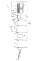
図1は、本発明の実施の形態による給紙装置を備えた画像読取装置の概略構成の一例を示した図である。この画像読取装置1は、給紙トレー11、分離部21、超音波センサー22、搬送ローラ17〜20、原稿読取部23,24、排紙トレー25、モーター31、動力伝達部32及びクラッチ部33により構成される。
FIG. 1 is a diagram illustrating an example of a schematic configuration of an image reading apparatus including a paper feeding device according to an embodiment of the present invention. The image reading apparatus 1 includes a
画像読取装置1では、紙媒体が給紙トレー11内から取り出され、1枚ずつ分離して搬送路A2へ送出されるとともに、搬送ローラ17〜20によって搬送路A2内を搬送される。そして、原稿読取部23,24によって紙媒体から画像が読み取られ、読み取り済みの紙媒体が排紙トレー25内に排紙される。
In the image reading apparatus 1, the paper medium is taken out from the
給紙トレー11は、多数の紙媒体を収容するための収容部であり、未読み取りの原稿A1が積載されている。
The
分離部21は、ピックアップローラ12、第1の分離ローラ13及び第2の分離ローラ14からなり、給紙トレー11内の原稿A1を1枚ずつ分離して搬送路A2へ送出する動作を行っている。ピックアップローラ12は、原稿A1を送り方向に付勢することによって給紙トレー11内の原稿A1を1枚ずつ取り出し、給紙トレー11内から第1の分離ローラ13側へ送出するための分離ローラである。
The
ここでは、上方向に付勢された原稿台上に多数の原稿A1が積載されており、原稿A1の積載量に関わらず、最上部の原稿A1は、常にピックアップローラ12に当接しているものとする。
Here, a large number of documents A1 are stacked on a document table biased upward, and the uppermost document A1 is always in contact with the
第1の分離ローラ13及び第2の分離ローラ14は、ピックアップローラ12によって送出された原稿A1を1枚ずつ分離して搬送路A2へ送出するための分離装置である。第1の分離ローラ13は、原稿A1を送り方向に搬送するための分離ローラである。
The
第2の分離ローラ14は、重送状態の紙媒体に戻り方向の摩擦力を作用するための分離ローラであり、搬送中の原稿A1を挟むように第1の分離ローラ13と対向配置されている。つまり、第1の分離ローラ13が搬送路A2の上側に配置されているのに対して、第2の分離ローラ14は、搬送路A2の下側に配置されている。
The
この第2の分離ローラ14には、一定レベルを越えるトルクが付加された際に従動回転するようにトルクリミッタが設けられている。例えば、第2の分離ローラ14は、一定レベルを越えるトルクの付加によって従動回転する円筒状のドラムと、ドラムと同軸に配置され、ドラムの内周面に接触して当該ドラムを支持する支軸によって構成される。ドラムは、支軸に対して回転可能に保持される。
The
ここでは、第1の分離ローラ13がモーター31によって駆動されるのに対して、第2の分離ローラ14は、モーターによって駆動されないいわゆるノンアクティブリタードローラとなっている。
Here, the
また、第2の分離ローラ14には、戻り方向には送り方向に比べて小さなトルクで従動回転するように、ワンウェイクラッチが設けられている。このワンウェイクラッチは、上記支軸の送り方向の回転を規制し、戻り方向には回転可能に当該支軸を保持する連結器である。例えば、ワンウェイクラッチは、上記支軸を送り方向には回転させないように固定されている。つまり、このワンウェイクラッチは、上記ドラムの送り方向の回転時にはロックして上記支軸を回転させないようにし、ドラムの戻り方向の回転時にはロックが解除されて支軸を自由回転させる連結器となっている。
Further, the
超音波センサー22は、超音波を用いて搬送中の原稿A1が重送状態であるか否かを検知するためのセンサーであり、分離部21及び搬送ローラ17〜20間に配置されている。この超音波センサー22は、超音波を送出する送出部15と、原稿A1を透過した超音波を検出して検出信号を出力する検出部16とからなる。
The
送出部15は、電気パルス信号を超音波振動に変換して送出する発信器である。検出部16は、送出部15からの超音波を受信して超音波振動を電気信号に変換し、検出信号として出力する受信器である。送出部15及び検出部16は、反射波が送出部15に干渉しないようにするために、送出部15から送出された超音波が搬送中の原稿A1に対して斜め方向に入射するように配置されている。
The sending
送出部15では、原稿A1の搬送に合わせて、所定の時間間隔で、例えば、周波数が200kHzの超音波が送信される。
In the sending
送出部15及び検出部16は、搬送路A2を挟んで対向配置されており、送出部15から一方向に向けて送出された超音波は、当該一方向に伝搬して検出部16に入射する。ここでは、超音波センサー22が、第1の分離ローラ13と、搬送路A2上で第1の分離ローラ13に最も近い搬送ローラ、すなわち、最も上流側の搬送ローラ17との間に配置されている。
The sending
搬送ローラ17〜20は、搬送路A2上において搬送路A2内の原稿A1を送り方向に搬送するためのローラであり、いずれも搬送中の原稿A1を挟むように対向配置された一対のローラからなる。各搬送ローラ17〜20は、一方のローラがモーター31によって送り方向に駆動され、他方のローラが従動回転するようになっている。
The
搬送ローラ17は、最も上流側に配置された搬送ローラであり、下流側の搬送ローラ18との間に原稿読取部23が配置されている。つまり、搬送ローラ17は、第1の分離ローラ13及び第2の分離ローラ14によって送出された原稿A1を原稿読取部23側へ搬送する動作を行っている。
The
また、搬送ローラ18と、下流側の搬送ローラ19との間には、原稿読取部24が配置されている。搬送ローラ20は、最も下流側に配置された搬送ローラであり、上流側の搬送ローラ19によって送出された原稿A1を排紙トレー25内に搬送する動作を行っている。
A
なお、分離ローラ13と超音波センサー22との間、或いは、超音波センサー22と搬送ローラ17との間には、モーターによって駆動されないローラ、例えば、紙送りを規制するためのガイドローラが配置されていても良い。
A roller that is not driven by a motor, for example, a guide roller for regulating paper feeding, is disposed between the
原稿読取部23,24は、原稿A1に光を照射し、原稿A1から画像を光学的に読み取って画像データを生成する光学読取装置であり、いずれも露光用光源と、ミラー、集光レンズなどの光学素子と、CCDイメージセンサーなどの撮像素子などによって構成される。
The
原稿読取部23が、搬送路A2の上側に配置され、原稿A1の上側の面を読み取る読取装置であるのに対し、原稿読取部24は、搬送路A2の下側に配置され、原稿A1の下側の面を読み取る読取装置となっている。
The
排紙トレー25は、読み取り済みの原稿A3を収容するための収容部であり、搬送ローラ20によって送出された原稿A1が積載される。
The
動力伝達部32は、モーター31の駆動力をピックアップローラ12、第1の分離ローラ13及び搬送ローラ17〜20に伝達するための伝達機構であり、複数の歯車などによって構成される。
The
クラッチ部33は、紙送りのタイミングを制御するために、ピックアップローラ12及び第1の分離ローラ13への駆動力伝達を必要に応じて遮断する連結機構である。
The
ここでは、モーター31の回転を反転させてピックアップローラ12及び第1の分離ローラ13の回転を反転させた際には、これらの分離ローラに連動して搬送ローラ17〜20の回転も反転する。
Here, when the rotation of the
図2は、図1の画像読取装置1の要部における給紙時の動作の一例を示した図であり、分離ローラ13,14と搬送ローラ17との間に紙媒体が存在しない場合が示されている。第1の分離ローラ13及び第2の分離ローラ14間に紙媒体が挟み込まれていない状態では、第1の分離ローラ13及び第2の分離ローラ14が当接することとなる。
FIG. 2 is a diagram illustrating an example of an operation at the time of paper feeding in the main part of the image reading apparatus 1 in FIG. 1, and shows a case where there is no paper medium between the
この状態では、分離ローラ13の送り方向の回転によって、分離ローラ13から分離ローラ14に送り方向の摩擦力が付加される。これにより、分離ローラ14には、送り方向のトルクが付加され、この送り方向のトルクが分離ローラ14内のトルクリミッタの上限値を越えることによって当該トルクリミッタがスリップし、分離ローラ14は送り方向に従動回転する。
In this state, a frictional force in the feed direction is applied from the
この図では、分離ローラ13の時計回りの回転が送り方向の回転となっており、反時計回りの回転が戻り方向の回転となっている。
In this figure, the clockwise rotation of the
図3は、図1の画像読取装置1の要部における給紙時の動作の一例を示した図であり、分離ローラ13及び14が1枚の原稿A10を挟み込んだ場合が示されている。第1の分離ローラ13及び第2の分離ローラ14が、1枚の原稿A10を挟み込んだ状態では、分離ローラ13の送り方向への回転による送り方向の付勢力が、原稿A10を介して分離ローラ13から分離ローラ14に付加されることとなる。
FIG. 3 is a diagram illustrating an example of an operation at the time of paper feeding in the main part of the image reading apparatus 1 in FIG. 1, and shows a case where the
このとき、上記付勢力によって分離ローラ14に付加される送り方向のトルクがトルクリミッタの上限値を越えていれば、分離ローラ14は送り方向に従動回転することになる。
At this time, if the torque in the feed direction applied to the
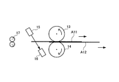
図4は、図1の画像読取装置1の要部における給紙時の動作の一例を示した図であり、分離ローラ13及び14が2枚の原稿A11,A12を挟み込んだ場合が示されている。第1の分離ローラ13及び第2の分離ローラ14が、複数枚の紙媒体を挟み込んだ状態では、分離ローラ13の送り方向への回転による送り方向の付勢力が、これらの紙媒体を介して分離ローラ13から分離ローラ14に付加されることとなる。
FIG. 4 is a diagram illustrating an example of an operation at the time of paper feeding in the main part of the image reading apparatus 1 in FIG. 1, in which the
ノンアクティブリタードローラの場合、ドラムの内周面に接触して当該ドラムを支持する支軸を送り方向には回転させないように、ワンウェイクラッチが固定されている。 In the case of a non-active retard roller, the one-way clutch is fixed so as not to contact the inner peripheral surface of the drum and rotate the support shaft that supports the drum in the feed direction.
このため、分離ローラ13の送り方向への回転による付勢力が重送状態の紙媒体を介して分離ローラ14に付加された場合であっても、分離ローラ14に付加される送り方向のトルクがトルクリミッタの上限値を越えていなければ、トルクリミッタはスリップせず、分離ローラ14は停止することになる。
For this reason, even when the urging force due to the rotation of the
トルクリミッタの上限値は、分離ローラ13,14の作用によって重送状態を自動的に解消させられるように、原稿が存在しないか、或いは、1枚の原稿を挟み込んだ状態で分離ローラ14に付加されるトルクと、2枚以上の原稿を挟み込んだ状態で付加されるトルクとに基づいて予め定められる。
The upper limit value of the torque limiter is added to the
上側の原稿A11が分離ローラ13の回転によって送り方向へ移動するのに対して、下側の原稿A12は、分離ローラ14の回転が停止するのに伴って停止する。重送が生じた際には、この様な分離ローラ13,14の作用により、重送している原稿が分離され、重送状態が自動的に解消される。
The upper document A11 moves in the feeding direction by the rotation of the
ところが、上側の原稿A11と下側の原稿A12との間の摩擦力が大きい場合には、分離ローラ14のトルクリミッタがスリップし、下側の原稿A12が上側の原稿A11と共に送り方向に移動することとなる。この様な場合には、重送状態のまま原稿A11,A12が下流側の搬送ローラ17へ搬送されることになる。
However, when the frictional force between the upper document A11 and the lower document A12 is large, the torque limiter of the
図5は、図1の画像読取装置1の要部における構成例を示した図であり、第2の分離ローラ14の一例が模式的に示されている。この第2の分離ローラ14は、ワンウェイクラッチ機構付きのノンアクティブリタードローラであり、ドラム2、スリーブ3及びワンウェイクラッチ機構4からなる。
FIG. 5 is a diagram illustrating a configuration example of a main part of the image reading apparatus 1 in FIG. 1, and schematically illustrates an example of the
ドラム2は、第1の分離ローラ13からの一定レベルを越えるトルクの付加によって従動回転する円筒状の回転体である。スリーブ3は、ドラム2と同軸に配置され、ドラム2の内周面に接触して当該ドラム2を支持する支軸であって、支軸に対してドラム2を回転可能に保持している。ドラム2の内周面とスリーブ3の外周面との間の摩擦力を利用してトルクリミッタが構成されている。
The
ワンウェイクラッチ機構4は、スリーブ3の送り方向の回転、すなわち、反時計回りの回転を規制し、戻り方向、すなわち、時計回りの回転方向には回転可能に当該スリーブ3を保持するための装置である。この例では、固定された軸部と、スリーブ3の内周面に取り付けられ、軸部の周面上に形成された歯と噛み合わせる板ばねによって構成されている。
The one-way clutch mechanism 4 is a device for restricting rotation of the
このワンウェイクラッチ機構では、ドラム2が送り方向に従動回転する場合、上記軸部とスリーブ3とがロック(連結状態)する。一方、ドラム2が戻り方向に従動回転する場合には、軸部及びスリーブ3間のロックは解除され、ドラム2は空回りすることとなる。
In this one-way clutch mechanism, when the
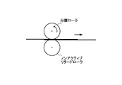
図6は、従来の給紙装置におけるノンアクティブリタードローラの動作を示した図であり、重送発生時に分離ローラの回転を反転させた場合が示されている。従来の給紙装置では、重送発生時に、分離ローラの回転を反転させた場合、重送状態の紙媒体のうち、上側の原稿は、分離ローラの戻り方向の回転による付勢力によって戻り方向に移動する。これに対して、下側の原稿は、内蔵するトルクリミッタにより回転が規制されたリタードローラとの摩擦力によってその位置に留まることになる。 FIG. 6 is a diagram showing the operation of the non-active retard roller in the conventional paper feeding device, and shows the case where the rotation of the separation roller is reversed when double feed occurs. In the conventional paper feeder, when the rotation of the separation roller is reversed at the time of occurrence of double feeding, the upper document among the paper media in the double feeding state is returned in the return direction by the urging force by the rotation of the separation roller in the return direction. Moving. On the other hand, the lower document stays at that position due to the frictional force with the retard roller whose rotation is restricted by the built-in torque limiter.
つまり、重送状態の原稿を収容部内に戻すために分離ローラを反転させたとしても、重送状態の原稿が正しく戻らないという問題があった。また、分離ローラの戻り方向の回転を継続させることによって、上側の原稿が収容部内に戻された後、下側の原稿も収容部内に戻すことができたとしても、その場合には、上側の原稿の先端が下側の原稿の先端よりも上流側の位置にセットされた状態となってしまう。 That is, there is a problem that even if the separation roller is reversed to return the double-fed original to the storage unit, the double-fed original does not return correctly. Further, by continuing the rotation of the separation roller in the return direction, even if the lower document can be returned into the storage unit after the upper document is returned into the storage unit, The leading edge of the document is set at a position upstream of the leading edge of the lower document.
図7は、図1の画像読取装置1における重送発生時の動作の一例を示した図であり、分離ローラ13の回転を反転させた場合が示されている。この画像読取装置1では、重送が検知された際、モーター31の回転を反転させることによって、第1の分離ローラ13の回転を反転させる。
FIG. 7 is a diagram showing an example of the operation at the time of occurrence of double feeding in the image reading apparatus 1 of FIG. 1, and shows a case where the rotation of the
その際、第2の分離ローラ14は、ワンウェイクラッチ機構4の作用によって、スリーブ3が自由回転状態となるので、第1の分離ローラ13からの付勢力によって戻り方向に従動回転することとなる。これにより、分離ローラ13,51に挟まれた重送状態の原稿を正しく給紙トレー11内に戻させることができる。
At that time, since the
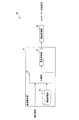
図8は、図1の画像読取装置1における給紙制御部40の構成例を示したブロック図である。この給紙制御部40は、超音波センサー22からの検出信号に基づいて重送を検知する重送検知部41と、その検知結果に基づいてモーター反転信号を出力する搬送制御部45によって構成される。
FIG. 8 is a block diagram showing a configuration example of the paper
重送検知部41は、閾値記憶部42、比較部43及び重送判別部44からなり、検出部16からの検出信号に基づいて、搬送中の原稿A1が重送であるか否かを判別する動作を行っている。具体的には、比較部43が、検出信号に基づいて超音波の受信レベルを判断し、閾値記憶部42内に保持された所定の閾値と比較する。重送判別部44は、比較部43による比較結果に基づいて、搬送中の原稿A1が重送状態であるか否かを判別する。
The double
搬送制御部45は、重送判別部44による判別結果に基づいて、原稿A1の搬送を制御する動作を行っている。具体的には、重送が検知された際、まず、クラッチ部33を制御し、重送状態の紙媒体が搬送ローラ17に到達するまでの間にピックアップローラ12及び第1の分離ローラ13を停止させる動作が行われる。
The
そして、重送状態の紙媒体よりも先行する原稿の読み取りが完了し、当該原稿が排出された後に、モーター31の回転を反転させてピックアップローラ12、第1の分離ローラ13及び搬送ローラ17〜20の回転を反転させる動作が行われる。
Then, after the reading of the document preceding the paper medium in the double-feed state is completed and the document is discharged, the rotation of the
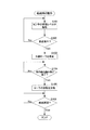
図9のステップS101〜S106は、図1の画像読取装置1における給紙時の動作の一例を示したフローチャートである。まず、重送検知部41は、超音波センサー22の受信レベルを取得し、予め定められた閾値と比較することによって搬送中の原稿A1が重送であるか否かを検知する(ステップS101,S102)。
Steps S <b> 101 to S <b> 106 in FIG. 9 are flowcharts illustrating an example of an operation during paper feeding in the image reading apparatus 1 in FIG. 1. First, the double
次に、搬送制御部45は、搬送中の原稿A1が重送であると判別された場合、ピックアップローラ12及び分離ローラ13を直ちに停止させる(ステップS103)。
Next, when it is determined that the document A1 being transported is double-feed, the
次に、搬送制御部45は、ピックアップローラ12及び分離ローラ13の停止によって重送状態の紙媒体の搬送を停止させた後、当該紙媒体よりも先行する紙媒体の読み取りが完了し、当該先行紙が排出されれば、モーター31の回転を反転させてピックアップローラ12、分離ローラ13及び搬送ローラ17〜20の回転を反転させる(ステップS104,S105)。
Next, the
次に、搬送制御部45は、給紙を再開するか否かを判断し、給紙を再開させる場合にはこの処理を終了する(ステップS106)。
Next, the
本実施の形態によれば、紙媒体を透過した超音波に基づいて搬送中の紙媒体が重送であるか否かが判別されるので、完全に重なった状態で重送している紙媒体であっても重送を検知することができる。しかも、分離ローラ13,14と搬送ローラ17との間に配置された超音波センサー22の出力に基づいて重送であるか否かを判別してピックアップローラ12及び分離ローラ13を停止させるので、重送状態の紙媒体を搬送路A2内に残しつつ当該紙媒体よりも先行する紙媒体の搬送を継続させることができる。
According to the present embodiment, since it is determined whether or not the paper medium being transported is a double feed based on the ultrasonic wave that has passed through the paper medium, the paper medium that is being double fed in a completely overlapped state Even so, double feeding can be detected. In addition, the
さらに、第2の分離ローラ14が、第1の分離ローラ13から一定レベルを越える送り方向のトルクが付加された際には従動回転し、戻り方向には送り方向に比べて小さなトルクで従動回転する分離ローラであるので、第1の分離ローラ13の回転を反転させた際に戻り方向に従動回転させることができる。従って、重送が検知された際に第1の分離ローラ13の回転を反転させることによって、第1の分離ローラ13及び第2の分離ローラ14に挟まれた重送状態の紙媒体を給紙トレー11内に正しく戻させることができる。特に、重送状態の紙媒体に戻り方向の摩擦力を及ぼすための分離ローラがモーターによって駆動されないノンアクティブリタード方式の給紙装置において、当該分離ローラにワンウェイクラッチ機構を設けることによって、構成がシンプルで低コストの給紙装置において、分離ローラに挟まれた重送状態の紙媒体を収容部内に正しく戻させることができる。
Furthermore, the
なお、本実施の形態では、給紙装置を備えた画像読取装置1の例について説明したが、本発明はこれに限られるものではない。例えば、記録紙に画像を印刷する印刷装置にも本発明は適用することができる。 In the present embodiment, the example of the image reading apparatus 1 including the paper feeding device has been described. However, the present invention is not limited to this. For example, the present invention can be applied to a printing apparatus that prints an image on recording paper.
1 画像読取装置
2 ドラム
3 スリーブ
4 ワンウェイクラッチ機構
11 給紙トレー
12 ピックアップローラ
13 第1の分離ローラ
14 第2の分離ローラ
15 送出部
16 検出部
17〜20 搬送ローラ
21 分離部
22 超音波センサー
23,24 原稿読取部
25 排紙トレー
31 モーター
32 動力伝達部
33 クラッチ部
40 給紙制御部
41 重送検知部
42 閾値記憶部
43 比較部
44 重送判別部
45 搬送制御部
A1,A3 原稿
A2 搬送路
DESCRIPTION OF SYMBOLS 1
Claims (4)
超音波を送出する送出部、及び、上記紙媒体を透過した上記超音波を検出する検出部からなり、上記分離部と当該分離部に最も近い上記搬送ローラとの間に配置された超音波センサーと、
上記検出部の出力に基づいて、搬送中の紙媒体が重送であるか否かを判別する重送検知部と、
上記重送検知部による判別結果に基づいて、上記紙媒体の搬送を制御する搬送制御部とを備え、
上記分離部は、モーターによって駆動される分離ローラであって、上記紙媒体を送り方向に搬送するための第1の分離ローラと、
第1の分離ローラの回転によって従動回転する分離ローラであって、一定レベルを越える送り方向のトルクが付加された際に従動回転し、戻り方向には送り方向に比べて小さなトルクで従動回転する第2の分離ローラとからなり、
上記搬送制御部は、重送が検知された際に、第1の分離ローラの回転を反転させることを特徴とする給紙装置。 A storage unit that stores a large number of paper media, a separation unit that separates the paper media in the storage unit one by one and sends them to a transport path, and two or more transport rollers that transport the paper medium on the transport path; In a paper feeder having
An ultrasonic sensor comprising a sending unit for sending ultrasonic waves and a detecting unit for detecting the ultrasonic waves transmitted through the paper medium, and disposed between the separating unit and the transport roller closest to the separating unit When,
Based on the output of the detection unit, a double feed detection unit for determining whether or not the paper medium being conveyed is double feed,
A conveyance control unit that controls conveyance of the paper medium based on the determination result by the double feed detection unit;
The separation unit is a separation roller driven by a motor, and a first separation roller for conveying the paper medium in a feeding direction;
A separation roller that is driven to rotate by the rotation of the first separation roller, and is driven to rotate when a torque in the feed direction exceeding a certain level is applied, and is driven to rotate in the return direction with a smaller torque than the feed direction. A second separating roller,
The conveyance control unit reverses the rotation of the first separation roller when double feeding is detected.
上記ドラムの内周面に接触して当該ドラムを支持する支軸と、
上記支軸の送り方向の回転を規制し、戻り方向には回転可能に当該支軸を保持するワンウェイクラッチとからなることを特徴とする請求項1に記載の給紙装置。 The second separation roller includes a cylindrical drum that rotates following the application of torque in the feed direction exceeding a certain level from the first separation roller;
A spindle that contacts the inner peripheral surface of the drum and supports the drum;
The sheet feeding device according to claim 1, further comprising a one-way clutch that restricts rotation of the support shaft in a feeding direction and rotatably supports the support shaft in a return direction.
Priority Applications (1)
| Application Number | Priority Date | Filing Date | Title |
|---|---|---|---|
| JP2008163969A JP5136237B2 (en) | 2008-06-24 | 2008-06-24 | Paper feeder |
Applications Claiming Priority (1)
| Application Number | Priority Date | Filing Date | Title |
|---|---|---|---|
| JP2008163969A JP5136237B2 (en) | 2008-06-24 | 2008-06-24 | Paper feeder |
Publications (2)
| Publication Number | Publication Date |
|---|---|
| JP2010006477A true JP2010006477A (en) | 2010-01-14 |
| JP5136237B2 JP5136237B2 (en) | 2013-02-06 |
Family
ID=41587435
Family Applications (1)
| Application Number | Title | Priority Date | Filing Date |
|---|---|---|---|
| JP2008163969A Expired - Fee Related JP5136237B2 (en) | 2008-06-24 | 2008-06-24 | Paper feeder |
Country Status (1)
| Country | Link |
|---|---|
| JP (1) | JP5136237B2 (en) |
Cited By (2)
| Publication number | Priority date | Publication date | Assignee | Title |
|---|---|---|---|---|
| JP2017178617A (en) * | 2016-03-31 | 2017-10-05 | 京セラドキュメントソリューションズ株式会社 | Sheet supply device, image formation apparatus and sheet supply method |
| JP2018052684A (en) * | 2016-09-29 | 2018-04-05 | 株式会社リコー | Sheet material conveyance device, image reading device and image forming apparatus |
Citations (2)
| Publication number | Priority date | Publication date | Assignee | Title |
|---|---|---|---|---|
| JP2006232485A (en) * | 2005-02-25 | 2006-09-07 | Canon Electronics Inc | Sheet conveying device and sheet treatment device |
| JP2008120493A (en) * | 2006-11-09 | 2008-05-29 | Sharp Corp | Sheet conveying device and automatic document feeding device and image forming device equipped with the sheet conveying device |
-
2008
- 2008-06-24 JP JP2008163969A patent/JP5136237B2/en not_active Expired - Fee Related
Patent Citations (2)
| Publication number | Priority date | Publication date | Assignee | Title |
|---|---|---|---|---|
| JP2006232485A (en) * | 2005-02-25 | 2006-09-07 | Canon Electronics Inc | Sheet conveying device and sheet treatment device |
| JP2008120493A (en) * | 2006-11-09 | 2008-05-29 | Sharp Corp | Sheet conveying device and automatic document feeding device and image forming device equipped with the sheet conveying device |
Cited By (2)
| Publication number | Priority date | Publication date | Assignee | Title |
|---|---|---|---|---|
| JP2017178617A (en) * | 2016-03-31 | 2017-10-05 | 京セラドキュメントソリューションズ株式会社 | Sheet supply device, image formation apparatus and sheet supply method |
| JP2018052684A (en) * | 2016-09-29 | 2018-04-05 | 株式会社リコー | Sheet material conveyance device, image reading device and image forming apparatus |
Also Published As
| Publication number | Publication date |
|---|---|
| JP5136237B2 (en) | 2013-02-06 |
Similar Documents
| Publication | Publication Date | Title |
|---|---|---|
| JP5219564B2 (en) | Sheet feeding apparatus, image reading apparatus, and image forming apparatus | |
| JP7211794B2 (en) | MEDIUM CONVEYING DEVICE, CONTROL METHOD AND CONTROL PROGRAM | |
| US20040140606A1 (en) | Original transport apparatus, original transport method and image reading apparatus | |
| JP2010001137A (en) | Paper feeder | |
| JP2023087063A (en) | Medium conveyance device, control method and control program | |
| JP5556777B2 (en) | Sheet-through type document reader | |
| JP5136237B2 (en) | Paper feeder | |
| JP4391153B2 (en) | Document reader | |
| JP4695007B2 (en) | Sheet conveying apparatus, sheet feeding apparatus including the same, and image processing apparatus | |
| JP2010095373A (en) | Sheet-like material conveying device | |
| JP5436792B2 (en) | Sheet feeding apparatus and image reading apparatus | |
| US20110272876A1 (en) | Sheet conveying device, image forming apparatus, and sheet conveying method | |
| US10091393B2 (en) | Document conveying device, document reading apparatus, and document conveying method | |
| JP2006111373A (en) | Sheet carrying device, and image reading device | |
| US9100523B2 (en) | Image forming apparatus comprising a sheet feeding device and an image reading device | |
| JP3931865B2 (en) | Automatic document feeder | |
| JP2020152542A (en) | Medium transport device, control method and control program | |
| JP2005015122A (en) | Automatic document conveying device and image formation device provided with this | |
| WO2005001759A2 (en) | Image-processing device, document-reading device, electronic apparatus, and document-reading method | |
| JP2014047044A (en) | Sheet conveying device and image reading device | |
| JP2012166922A (en) | Paper feeder and image forming apparatus including the same | |
| WO2023145023A1 (en) | Medium conveying device, medium feeding method, and control program | |
| JP2018061095A (en) | Sheet conveying device, image reading device, image forming apparatus, and sheet conveying method | |
| JP2022078743A (en) | Sheet conveyance apparatus and image reader | |
| JP2009078903A (en) | Automatic document feeder, image reading device and image forming device |
Legal Events
| Date | Code | Title | Description |
|---|---|---|---|
| A621 | Written request for application examination |
Free format text: JAPANESE INTERMEDIATE CODE: A621 Effective date: 20110418 |
|
| A977 | Report on retrieval |
Free format text: JAPANESE INTERMEDIATE CODE: A971007 Effective date: 20120726 |
|
| A131 | Notification of reasons for refusal |
Free format text: JAPANESE INTERMEDIATE CODE: A131 Effective date: 20120731 |
|
| A521 | Request for written amendment filed |
Free format text: JAPANESE INTERMEDIATE CODE: A523 Effective date: 20120910 |
|
| TRDD | Decision of grant or rejection written | ||
| A01 | Written decision to grant a patent or to grant a registration (utility model) |
Free format text: JAPANESE INTERMEDIATE CODE: A01 Effective date: 20121016 |
|
| A01 | Written decision to grant a patent or to grant a registration (utility model) |
Free format text: JAPANESE INTERMEDIATE CODE: A01 |
|
| A61 | First payment of annual fees (during grant procedure) |
Free format text: JAPANESE INTERMEDIATE CODE: A61 Effective date: 20121029 |
|
| R150 | Certificate of patent or registration of utility model |
Ref document number: 5136237 Country of ref document: JP Free format text: JAPANESE INTERMEDIATE CODE: R150 Free format text: JAPANESE INTERMEDIATE CODE: R150 |
|
| FPAY | Renewal fee payment (event date is renewal date of database) |
Free format text: PAYMENT UNTIL: 20151122 Year of fee payment: 3 |
|
| R250 | Receipt of annual fees |
Free format text: JAPANESE INTERMEDIATE CODE: R250 |
|
| R250 | Receipt of annual fees |
Free format text: JAPANESE INTERMEDIATE CODE: R250 |
|
| R250 | Receipt of annual fees |
Free format text: JAPANESE INTERMEDIATE CODE: R250 |
|
| R250 | Receipt of annual fees |
Free format text: JAPANESE INTERMEDIATE CODE: R250 |
|
| R250 | Receipt of annual fees |
Free format text: JAPANESE INTERMEDIATE CODE: R250 |
|
| R250 | Receipt of annual fees |
Free format text: JAPANESE INTERMEDIATE CODE: R250 |
|
| LAPS | Cancellation because of no payment of annual fees |