JP2010006331A - Vehicular convertible top driving structure - Google Patents
Vehicular convertible top driving structure Download PDFInfo
- Publication number
- JP2010006331A JP2010006331A JP2008170923A JP2008170923A JP2010006331A JP 2010006331 A JP2010006331 A JP 2010006331A JP 2008170923 A JP2008170923 A JP 2008170923A JP 2008170923 A JP2008170923 A JP 2008170923A JP 2010006331 A JP2010006331 A JP 2010006331A
- Authority
- JP
- Japan
- Prior art keywords
- drive source
- convertible top
- frame
- rear end
- rear side
- Prior art date
- Legal status (The legal status is an assumption and is not a legal conclusion. Google has not performed a legal analysis and makes no representation as to the accuracy of the status listed.)
- Granted
Links
Images


Abstract
Description
本願発明は、自動で開閉されるコンバーチブルトップの後端側にトノカバーが配置され、且つ該コンバーチブルトップのクローズ状態においては該コンバーチブルトップも後端部分が上記トノカバーの前面側の衝合される構成の車両用コンバーチブルトップにおいて好適な駆動構造に関するものである。 The present invention has a configuration in which a tonneau cover is disposed on the rear end side of the convertible top that is automatically opened and closed, and in the closed state of the convertible top, the rear end portion of the convertible top also abuts on the front side of the tonneau cover. The present invention relates to a drive structure suitable for a convertible top for a vehicle.
オープンカーのルーフ部分を構成する車両用コンバーチブルトップに関しては従来から種々の構造が提案されている(例えば、特許文献1、特許文献2参照)。これら各特許文献に示されるコンバーチブルトップでは、クローズ状態における後部形体を、ルーフ部後端から車体後方側へ滑らかに下降傾斜する流線型に形成し、この下降傾斜部分にバックガラスを取付けるのが通例である。 Conventionally, various structures have been proposed for a convertible top for a vehicle that constitutes a roof portion of an open car (see, for example, Patent Document 1 and Patent Document 2). In the convertible top shown in each of these patent documents, the rear shape in the closed state is usually formed into a streamlined shape that smoothly descends from the rear end of the roof portion toward the rear side of the vehicle body, and the back glass is attached to the descending inclined portion. is there.
ところで、近年は、コンバーチブルトップの後部形体を、ルーフ後端部において縦方向に切り落とし車体後方側へ開口させる一方、該コンバーチブルトップの後方側に設けられるトノカバーを、車幅方向の両側部のみを上記コンバーチブルトップのルーフ部後端から車体後方側へ滑らかに下降傾斜するような流線型に隆起形成し、この左右の隆起形成部の中間部分は低位の平板状に形成し、係る形態をもつトノカバーの前端面にバックガラスを取付けたものが提案されている。そして、コンバーチブルトップのクローズ状態では、該コンバーチブルトップの後端部を上記トノカバー側の上記バックガラスに衝合させてシール性を確保するようにしている(図1、図4参照)。 By the way, in recent years, the rear shape of the convertible top is cut off in the longitudinal direction at the rear end of the roof and opened to the rear side of the vehicle body, while the tonneau cover provided on the rear side of the convertible top has only the both sides in the vehicle width direction described above. The convertible top has a streamlined bulge that smoothly descends and tilts from the rear end of the roof to the rear side of the vehicle body, and the middle part of the left and right bulge formations is formed in a lower flat plate shape. The thing which attached the back glass to the surface is proposed. In the closed state of the convertible top, the rear end portion of the convertible top is brought into contact with the back glass on the tonneau cover side to ensure a sealing property (see FIGS. 1 and 4).
このように、コンバーチブルトップのクローズ状態では、該コンバーチブルトップの後端部をトノカバーの前端面に取付けたバックガラスに衝合させてシール性を確保するようにした構成のものにあっては、コンバーチブルトップをクローズ状態からオープン状態側へ作動させる場合、即ち、上記コンバーチブルトップを後部側へ折り畳んでトノカバーの下側スペースに格納する場合、該コンバーチブルトップをクローズ状態のまま、上記トノカバーの前端側を上昇させて上記コンバーチブルトップの格納移動スペースを確保しようとしても、上述のようにコンバーチブルトップのクローズ状態では該コンバーチブルトップの後端部が上記トノカバーの前端面のバックガラスに衝合されていることから、該コンバーチブルトップの後端部によって上記トノカバーの前端部の上昇移動が規制され、所要の作動を実現できないことになる。 As described above, in the closed state of the convertible top, the convertible top having a configuration in which the rear end portion of the convertible top is brought into contact with the back glass attached to the front end surface of the tonneau cover to ensure the sealing property. When operating the top from the closed state to the open state side, that is, when folding the convertible top to the rear side and storing it in the lower space of the tonneau cover, the front end side of the tonneau cover is raised with the convertible top closed. Even if trying to secure the storage movement space of the convertible top, the back end portion of the convertible top is abutted against the back glass of the front end surface of the tonneau cover in the closed state of the convertible top as described above. By the rear end of the convertible top Upward movement of the front end of the tonneau cover is restricted Te, would not be achieved the required operation.
このため、係る構成のものにおいては、上記トノカバーの上昇移動(即ち、開作動)に先立って、上記コンバーチブルトップの後端部を車体前方側へ移動させて上記トノカバーのバックガラスに対する衝合状態を解消させ、しかる後、上記トノカバーを開作動させるようにしている。 For this reason, in such a configuration, the rear end portion of the convertible top is moved to the front side of the vehicle body before the tonneau cover moves upward (that is, the opening operation), and the tonneau cover is brought into an abutting state with respect to the back glass. After that, the tonneau cover is opened.
ここで、このようにトノカバーの開作動に先立ってコンバーチブルトップの後端側を該トノカバーの前端面から離脱させる場合、該コンバーチブルトップを支持する幌フレームの後端に位置して幌の後端縁を支持する後端ボウを幌フレーム側に引き寄せる手法が採用される。この場合、一般には、幌フレーム側に駆動源を配置し、該駆動源によって上記後端ボウを駆動させるのが一般的である。なお、トノカバーの構造は異なるが、幌フレーム側に後端ボウを駆動させるための駆動源としてシリンダを配置してものとして特許文献3に示されるものがある。
Here, when the rear end side of the convertible top is separated from the front end surface of the tonneau cover prior to the opening operation of the tonneau cover, the rear end edge of the hood is located at the rear end of the hood frame that supports the convertible top. A method is adopted in which the rear end bow that supports the wing is pulled toward the hood frame. In this case, generally, a drive source is arranged on the hood frame side, and the rear end bow is driven by the drive source. Although the structure of the tonneau cover is different, there is one disclosed in
ところが、このように幌フレーム側に後端ボウを駆動させるための駆動源を配置した駆動構造においては、
(ア)幌フレームの軽量化が阻害される、
(イ)設置スペース的な理由から、駆動源の種類が制約され、駆動方式の選択の自由度が損なわれる、
(ウ)駆動源の存在によって車室からの後方視界が妨げられる、
(エ)駆動源が車室内の乗員から近い位置に存在するため、該駆動源と人体の接触とか、作動音による快適性の阻害等の悪影響が懸念される、
等の問題がある。
However, in the drive structure in which the drive source for driving the rear end bow is arranged on the hood frame side in this way,
(A) The weight reduction of the hood frame is impeded.
(B) For reasons of installation space, the type of drive source is restricted, and the degree of freedom in selecting the drive method is impaired.
(C) Rear view from the passenger compartment is hindered by the presence of the drive source,
(D) Since the drive source is located at a position close to the passenger in the vehicle interior, there are concerns about adverse effects such as contact between the drive source and the human body, obstruction of comfort due to operating noise, etc.
There are problems such as.
そこで、本願発明では、幌フレームの軽量化とか、駆動方式の選択の自由度の向上等を図り得るようにした車両用コンバーチブルトップの駆動構造を提案することを目的としてなされたものである。 Accordingly, the present invention has been made for the purpose of proposing a drive structure for a convertible top for a vehicle that can reduce the weight of the hood frame and improve the degree of freedom in selecting the drive system.
本願発明ではかかる課題を解決するための具体的手段として次のような構成を採用している。 In the present invention, the following configuration is adopted as a specific means for solving such a problem.
本願の第1の発明では、折曲・展開可能とされた幌フレーム12によって幌11を支持し、該幌フレーム12の展開・折曲によって車室2の上方を開閉蓋するとともに、上記幌フレーム12の後方側には、開閉可能とされるとともに閉位置で且つ上記幌フレーム12の展開状態においては該幌フレーム12の後端に位置する後端ボウ17がその前面側に衝合されるトノカバー4が備えられた車両用コンバーチブルトップ10において、上記幌フレーム12の後端側に位置しその一端が枢支ピン51によって車体側に枢支され且つ車体側に配置された第1の駆動源Xによって回動されるリヤサイドフレーム16と、一端が上記後端ボウ17に固定される一方、他端が上記リヤサイドフレーム16の適所に相対回転可能に連結された支持アーム21と、一端が上記後端ボウ17に支点ピン56によって相対回転可能に連結される一方、他端には支点ピン57によってサブリンク61,62,66が連結され該サブリンク61,62,66を介して車体側に配置された第2の駆動源Yに連結されたコントロールアーム22を備え、上記コンバーチブルトップ10のクローズ状態からのオープン作動時には、上記第2の駆動源Yによって上記サブリンク61,62,66を介して上記コントロールアーム22を駆動して上記支点ピン57を上記リヤサイドフレーム16の上記枢支ピン51に重合する位置に位置させることで、上記後端ボウ17が上記トノカバー4の前面から離間して上記リヤサイドフレーム16寄りへ移動されるとともに、上記第1の駆動源Xによって上記リヤサイドフレーム16を、上記枢支ピン51を中心として車体後方側へ傾倒させるとき上記後端ボウ17が上記リヤサイドフレーム16との相対位置を維持したまま上記支点ピン57を中心として該リヤサイドフレーム16と一体的に傾倒されるように構成したことを特徴としている。
In the first invention of the present application, the
本願の第2の発明では、上記第1の発明に係る車両用コンバーチブルトップの駆動構造において、上記第1の駆動源Xと第2の駆動源Yが、共にモータユニット25、26で構成されていることを特徴としている。
In a second invention of the present application, in the drive structure for a convertible top for a vehicle according to the first invention, the first drive source X and the second drive source Y are both constituted by
本願の第3の発明では、上記第2の発明に係る車両用コンバーチブルトップの駆動構造において、上記各モータユニット25、26は、共にセクター23、24を介して上記リヤサイドフレーム16及び上記コントロールアーム22を駆動する構成としたことを特徴としている。
According to a third invention of the present application, in the drive structure for a convertible top for a vehicle according to the second invention, the
本願の第4の発明では、上記第1の発明に係る車両用コンバーチブルトップの駆動構造において、上記第1の駆動源Xと第2の駆動源Yが、共にシリンダユニット33、34で構成したことを特徴としている。
In the fourth invention of the present application, in the vehicle convertible top drive structure according to the first invention, the first drive source X and the second drive source Y are both composed of
本願発明では次のような効果が得られる。 In the present invention, the following effects can be obtained.
(a)本願の第1の発明に係るコンバーチブルトップの駆動構造によれば、上記第1の駆動源Xと第2の駆動源Yを車体側に配置し、上記コンバーチブルトップ10のクローズ状態からのオープン作動時には、これら第1の駆動源Xと第2の駆動源Yの作動によって上記後端ボウ17を上記トノカバー4の前面から離間させて上記リヤサイドフレーム16寄りへ移動させるとともに、上記リヤサイドフレーム16と上記後端ボウ17を一体的に傾倒させて上記トノカバー4の下側へ格納させることができるものである。
(A) According to the convertible top drive structure according to the first invention of the present application, the first drive source X and the second drive source Y are arranged on the vehicle body side, and the
従って、
(a−1) 上記第1の駆動源Xと第2の駆動源Yが上記幌フレーム12側に存在しないことから、
(a−1−1) 各駆動源X,Yによって車室内からの後方視界が妨げられることがなく、運転上の安全性が担保される、
(a−1−2) 車室内の居住空間が十分に確保され、車室内での快適性が向上する、
(a−1−3) 各駆動源X,Yと乗員の体との接触が可及的に防止されるとともに、該駆動源X,Yの運転音による不快感が低減され、車室内での安全性と快適性が確保される、
(a−1−4) 可動部材である上記幌フレーム12の構造の簡略化及び軽量化が促進されるとともに、作動時の安定性が向上する、
(a−2) 上記第1の駆動源Xと第2の駆動源Yが車体側に配置され、且つ該各駆動源X,Yが支持アーム21及びコントロールアーム22を介して上記後端ボウ17を駆動させる構成であることから、これら各部材の配置スペースの確保が容易であり、その結果、駆動方式の選択の自由度及びレイアウトの自由度が拡大する、
(a−3) 上記コントロールアーム22が上記サブリンク61,62,66を介して上記第2の駆動源Yにより駆動される構成であることから、該サブリンク61,62,66の作動領域分だけ上記コントロールアーム22と上記第2の駆動源Yの間隔を大きくとることができ、この結果、例えば、該第2の駆動源Yを車体側の余裕スペース部分に配置するなど、該第2の駆動源Yの車体側へのレイアウトの自由度が拡大される、
等の効果が得られる。
Therefore,
(A-1) Since the first drive source X and the second drive source Y do not exist on the
(A-1-1) The rear view from the passenger compartment is not obstructed by each drive source X, Y, and driving safety is ensured.
(A-1-2) The living space in the passenger compartment is sufficiently secured, and the comfort in the passenger compartment is improved.
(A-1-3) Contact between each driving source X, Y and the occupant's body is prevented as much as possible, and uncomfortable feeling due to the driving sound of the driving source X, Y is reduced. Safety and comfort are ensured,
(A-1-4) Simplification and weight reduction of the structure of the
(A-2) The first drive source X and the second drive source Y are disposed on the vehicle body side, and the drive sources X and Y are connected to the
(A-3) Since the
Etc. are obtained.
(b)本願の第2の発明に係るコンバーチブルトップの駆動構造によれば、上記(a)に記載の効果に加えて、以下のような特有の効果が得られる。即ち、この発明では、上記第1の駆動源Xと第2の駆動源Yを、共にモータユニット25、26で構成しているので、モータユニットの特性として、遠隔操作が容易であることから、上記各駆動源X,Yのレイアウトの自由度がさらに向上する。
(B) According to the convertible top drive structure of the second invention of the present application, in addition to the effect described in the above (a), the following specific effects can be obtained. That is, in the present invention, since the first drive source X and the second drive source Y are both constituted by the
(c)本願の第3の発明に係るコンバーチブルトップの駆動構造によれば、上記(b)に記載の効果に加えて、以下のような特有の効果が得られる。即ち、この発明では、上記各モータユニット25、26は、共にセクター23、24を介して上記リヤサイドフレーム16及び上記コントロールアーム22を駆動する構成としているので、該セクター23、24の形状の設定によって上記リヤサイドフレーム16及び後端ボウ17と、これらを駆動する上記各駆動源X,Yの間隔を調整することができ、該各駆動源X,Yのレイアウトの自由度がより一層向上する。
(C) According to the convertible top drive structure of the third invention of the present application, in addition to the effect described in the above (b), the following specific effect can be obtained. In other words, in the present invention, each of the
(d)本願の第4の発明に係るコンバーチブルトップの駆動構造によれば、上記(a)に記載の効果に加えて、以下のような特有の効果が得られる。即ち、この発明では、上記第1の駆動源Xと第2の駆動源Yを、共にシリンダユニット33、34で構成しているので、該シリンダユニット33、34の特性として、コンパクトな構成で大きな駆動力を発生し得ることから、駆動部分のコンパクト化が図れる。
(D) According to the convertible top drive structure of the fourth invention of the present application, in addition to the effect described in (a) above, the following specific effect is obtained. That is, in the present invention, since the first drive source X and the second drive source Y are both constituted by the
以下、本願発明に係る車両用コンバーチブルトップの駆動構造を具体的に説明する。
I:コンバーチブルトップの全体構成
図7〜図9には、コンバーチブルトップ10が備えられた車両1の要部を示しており、図7はコンバーチブルトップ10のクローズ状態を、図8はコンバーチブルトップ10のクローズ状態からオープン状態への過渡状態を、さらに図9はコンバーチブルトップ10のオープン状態を、それぞれ示している。
Hereinafter, the drive structure of the convertible top for a vehicle according to the present invention will be specifically described.
I: Overall Configuration of Convertible Top FIGS. 7 to 9 show the main part of the vehicle 1 provided with the convertible top 10, FIG. 7 shows the closed state of the convertible top 10, and FIG. 8 shows the
上記コンバーチブルトップ10は、上記車両1の車室2の上方を開閉蓋するものであって、次述の幌フレーム12とこの幌フレーム12によって展開・折畳可能に支持された幌11を備えて構成される。
The convertible top 10 opens and closes the upper portion of the
上記幌フレーム12は、該幌フレーム12の前端に位置して車幅方向に延出するフロントフレーム13と、該フロントフレーム13の左右両端にそれぞれその前端部が固定された左右一対の第1ルーフサイドフレーム14と該各第1ルーフサイドフレーム14の後端に相対回動自在に連結された左右一対の第2ルーフサイドフレーム15と、該各第2ルーフサイドフレーム15の後端に相対回動自在に連結されるとともにその下端部が上記車両1の車体内側部に配置した後述するベースプレート6に枢支された左右一対のリヤサイドフレーム16と、該幌フレーム12の後端に位置し且つ後述する支持アーム21とコントロールアーム22によって支持されて車幅方向に延びる後端ボウ17と、上記左右一対の第2ルーフサイドフレーム15間に跨って車幅方向に延びる中間ボウ18と、上記左右一対の第1ルーフサイドフレーム14間に跨って車幅方向に延びる前側ボウ19を備えて構成される。
The
そして、上記幌11は、その前端縁が上記幌フレーム12のフロントフレーム13に固定され、その後端縁が上記後端ボウ17に固定されるとともに、その左右の側縁が上記第1ルーフサイドフレーム14と第2ルーフサイドフレーム15及びリヤサイドフレーム16のよって支持され、さらにその車幅方向中間が上記中間ボウ18及び前側ボウ19によって支持されており、上記幌フレーム12の展延によって張設され(図7参照)、該幌フレーム12の折曲によって折り畳まれる(図9参照)。
The front end of the
そして、このコンバーチブルトップ10は、そのクローズ状態では、図7に示すように、上記車両1のフロントヘッダ3と次述するトノカバー4の前面部との間に跨って張設されて上記車室2の上方を閉蓋する一方、そのオープン状態では、図9に示すように、折畳状態で上記トノカバー4の下側に設けられた収納スペース内に収納され、上記車室2の上方を開放する。
In the closed state, the convertible top 10 is stretched between the
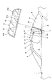
ここで、上記トノカバー4の構造を説明すると、該トノカバー4は、図7に示すように、車幅方向の両端部をそれぞれ上方へ隆起させ且つその前端から後端へ向けて流線状に下降傾斜させてこれを隆起部41a,41aとする一方、車幅方向中間部分は低位の平板状としてこれを低位部41bとしたカバー本体41と、若干後方へ傾斜した状態で立ち上がる該カバー本体41の前端面41cに、該前端面41cの略前面を覆うようにしてバックガラス42を固定的に取付けて構成される。
Here, the structure of the tonneau cover 4 will be described. As shown in FIG. 7, the tonneau cover 4 has both end portions in the vehicle width direction raised upward and descended in a streamline shape from the front end to the rear end. The
そして、このトノカバー4は、その後端側を支点として上下方向に開閉可能とされており、車体側に配置したトノカバー駆動シリンダ7によって開閉駆動され、図7に示す閉位置と図8に示す開位置の間で位置変更される。なお、このトノカバー4の開閉は、上記コンバーチブルトップ10の動作に連動して自動的に行なわれるようになっている。
The tonneau cover 4 can be opened and closed in the vertical direction with the rear end side as a fulcrum. The tonneau cover 4 is opened and closed by the tonneau cover drive cylinder 7 disposed on the vehicle body side, and is shown in the closed position shown in FIG. Repositioned between. The tonneau cover 4 is automatically opened and closed in conjunction with the operation of the
ところで、図7に示すように、上記コンバーチブルトップ10がクローズ状態に設定され、且つ上記トノカバー4が閉位置に設定された状態では、上記コンバーチブルトップ10の後端に位置する後端ボウ17(図1参照)が上記トノカバー4の上記バックガラス42にその上側から乗り掛かった状態で衝合されている。従って、上記コンバーチブルトップ10の作動に先立って、上記トノカバー4をその閉位置から開位置へ位置変更させて該トノカバー4の下側に上記コンバーチブルトップ10の屈曲移動のためのスペースを確保すべく、該トノカバー4を閉位置から開位置へ作動させようとしても、上記コンバーチブルトップ10の上記後端ボウ17が上記トノカバー4の前端面と干渉して該トノカバー4を開作動させることができないことになる。
By the way, as shown in FIG. 7, when the convertible top 10 is set in the closed state and the tonneau cover 4 is set in the closed position, the rear end bow 17 (see FIG. 7) located at the rear end of the convertible top 10 is shown. 1) is abutted against the
このため、上記トノカバー4の閉位置から開位置への作動に際しては、該トノカバー4の作動に先立って、図7に鎖線図示(符号17´参照)するように、上記コンバーチブルトップ10の後端に位置する上記後端ボウ17を車体前方側へ傾動させて上記トノカバー4のバックガラス42との衝合状態を解消し、該トノカバー4の開作動を許容し得る状態とする。この状態において、図8に示すように、上記トノカバー4を開作動させてこれを開位置に設定し、該トノカバー4の下側のスペースを通して上記コンバーチブルトップ10を屈曲させながら後傾させて、図9に示すように、該コンバーチブルトップ10を車体後部の収納室8に収納し、さらに上記トノカバー4を開位置から閉位置に作動させて上記コンバーチブルトップ10の上方を上記コンバーチブルトップ10によって覆う。
For this reason, when the tonneau cover 4 is operated from the closed position to the open position, prior to the operation of the tonneau cover 4, as shown by a chain line in FIG. 7 (see
このように、上記コンバーチブルトップ10をクローズ状態からオープン状態へ作動させる場合において上記コンバーチブルトップ10を適正状態で作動させる、即ち、上記幌フレーム12を適正に作動させるために、本願発明に係るコンバーチブルトップの駆動構造が採用されたものである。
Thus, in order to operate the convertible top 10 in an appropriate state when the convertible top 10 is operated from the closed state to the open state, that is, in order to operate the
以下、このコンバーチブルトップ10の駆動構造を、好適な実施形態に基づいて説明する。
II:コンバーチブルトップの駆動構造の具体的な構成
II−1:第1の実施形態(図1〜図3参照)
II−1−a:具体的な構造
第1の実施形態に係る駆動構造は、駆動手段として電動機構を採用したものである。
Hereinafter, the drive structure of the convertible top 10 will be described based on a preferred embodiment.
II: Specific Configuration of Convertible Top Drive Structure II-1: First Embodiment (see FIGS. 1 to 3)
II-1-a: Specific Structure The drive structure according to the first embodiment employs an electric mechanism as drive means.
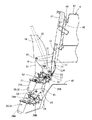
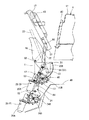
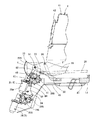
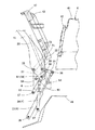
ここで、図1は、図7に示すコンバーチブルトップ10のクローズ状態におけるリンク構成を示している。図2は、図8に示すコンバーチブルトップ10のクローズ状態からオープン状態への作動の過渡期におけるリンク構成を示している。図3は、図9に示すコンバーチブルトップ10のオープン状態におけるリンク構成を示している。 Here, FIG. 1 shows a link configuration in the closed state of the convertible top 10 shown in FIG. FIG. 2 shows a link configuration in the transitional period from the closed state to the open state of the convertible top 10 shown in FIG. FIG. 3 shows a link configuration in the open state of the convertible top 10 shown in FIG.
図1〜図3において、符号16は、上記幌フレーム12の後端寄りに位置する上記リヤサイドフレームであって、このリヤサイドフレーム16は、枢支ピン51によって、車体内側部に固定配置されたベースプレート6に枢支され、車体前後方向へ回動自在とされている。
1 to 3,
また、このリヤサイドフレーム16の下端部には、略扇形の平面形体をもち且つその外周縁にはセレクトギヤ23Aが形成された第1セクター23が、該セレクトギヤ23Aの回転中心を上記枢支ピン51の軸心に一致させた状態で固定されている。さらに、この第1セクター23のセレクトギヤ23Aには、車体側に固定配置された第1モータユニット25に設けられたピニオンギヤ25Bが噛合されている。従って、上記第1モータユニット25のモータ25Aの駆動力によって上記ピニオンギヤ25Bが回転駆動されることで、上記第1セクター23は上記リヤサイドフレーム16と一体的に上記枢支ピン51を中心として回動されることになる。なお、この実施形態では、上記第1モータユニット25が特許請求の範囲中の「第1の駆動源X」に該当する。
Further, a
図1〜図3において、符号17は、上記幌フレーム12の最後端に位置して上記幌11の後端縁を支持する後端ボウであって、この後端ボウ17の後方側の面にはシール材43が取付けられており、該後端ボウ17を介して上記シール材43が上記トノカバー4側のバックガラス42に衝合されることで、上記幌11の後端縁と上記バックガラス42の間のシール性が確保されている。
In FIG. 1 to FIG. 3,
上記後端ボウ17の下端部には、略L形に湾曲形成された支持アーム21の一端側が固定されている。この支持アーム21の他端は、支点ピン55によって、上記リヤサイドフレーム16における上記枢支ピン51の近傍位置に連結されている。
One end side of a
さらに、上記後端ボウ17の下端部には、コントロールアーム22の一端が支点ピン56によって回転可能に枢支されるとともに、該コントロールアーム22の他端は支点ピン57を介してサブリンク62の一端に連結されている。このサブリンク62は、その他端が支点ピン63によって車体側に枢支されるとともに、その中間位置には枢支ピン65によってサブリンク61の一端が連結されている。さらに、このサブリンク61の他端は、枢支ピン64によって次述の第2セクター24の一端に連結されている。
Further, one end of the
上記第2セクター24は、略L形の板体で構成され、その長手方向の中間部が枢支ピン52によって車体側に枢支されている。この第2セクター24の一端は上記支点ピン57によって上記コントロールアーム22の他端に連結される一方、その他端は略扇形の平面形体をもち且つその外周には上記枢支ピン52を回転中心とするセレクトギヤ24Aが形成されている。そして、この第2セクター24のセレクトギヤ24Aには、車体側に固定配置された第2モータユニット26に設けられたピニオンギヤ26Bが噛合されている。
The
従って、上記第2モータユニット26のモータ26Aの駆動力によって上記ピニオンギヤ26Bが回転駆動されることで、上記第2セクター24は上記枢支ピン52を中心として回動され、さらにこの第2セクター24の回動に伴って上記サブリンク61及びサブリンク62を介して上記第2リンク22が作動されることになる。なお、この実施形態では、上記第2モータユニット26が特許請求の範囲中の「第2の駆動源Y」に該当する。
Accordingly, when the
ここで、上記サブリンク62の他端を枢支する上記支点ピン63の配置位置は、該支点ピン63と該サブリンク62の一端を枢支する上記支点ピン57の間隔と、該支点ピン63と上記リヤサイドフレーム16側の上記枢支ピン51の間隔が同一となるように設定されている。換言すれば、上記サブリンク62が上記支点ピン63回りに回動する場合における軌跡L上に上記枢支ピン51が位置するように設定されている。従って、上記第2セクター24による上記サブリンク62の回動角度を所定値に規定することで、図2に示すように、上記支点ピン57と上記枢支ピン51を同一位置において重合させることができる。
Here, the arrangement position of the
なお、図1〜図3において、符号20は、上記幌フレーム12の折曲・展開作動を制御するコントロールリンクであり、その一端は枢支ピン53によって上記ベース体6に枢支され、他端は上記幌フレーム12の上記第2ルーフサイドフレーム15の端部に連結されている(図7参照)。
II−1−b:作動の説明
(b−1) 上記コンバーチブルトップ10のクローズ状態
上記コンバーチブルトップ10がクローズ状態にあるときには、上記各部材は図1に示すような位置関係にある。即ち、上記リヤサイドフレーム16は立設状態にあり、上記第1セクター23のセクターギヤ23Aの一端寄り位置に上記第1モータユニット25のピニオンギヤ25Bが噛合し、これによって該リヤサイドフレーム16が立設状態に保持されている。
1 to 3,
II-1-b: Explanation of operation (b-1) Closed state of the convertible top 10 When the convertible top 10 is in the closed state, the respective members are in a positional relationship as shown in FIG. That is, the
また、上記第2セクター24における上記セクターギヤ24Aの一端寄り位置に上記第2モータユニット26のピニオンギヤ26Bが噛合しており、これによって上記第2セクター24が後傾状態に保持されている。そして、上記サブリンク61及びサブリンク62を介して上記コントロールアーム22は突き上げ状態とされている。
In addition, the
ここで、上記後端ボウ17は、上記第2セクター24に連結された上記コントロールアーム22によってその高さが規定されるとともに、この高さに対応して所定の傾動状態に姿勢保持された上記支持アーム21によってその傾動角度が規定されるようになっており、この高さと傾動角度の規制によって、該後端ボウ17に設けた上記シール材43は、閉位置に設定された上記トノカバー4の前端面に位置する上記バックガラス42に衝合され、これら両者間のシール性が確保されている。
Here, the height of the
(b−2) 上記コンバーチブルトップ10のクローズ状態からオープン状態への作動時
上記コンバーチブルトップ10のクローズ状態からオープン状態への作動時には、先ず、図1に示した状態から上記第2モータユニット26が作動され、上記後端ボウ17の姿勢変更が行なわれる。
(B-2) When the convertible top 10 is operated from the closed state to the open state When the convertible top 10 is operated from the closed state to the open state, first, the
即ち、図1の状態において、先ず、上記第2モータユニット26を作動させ、上記ピニオンギヤ26Bの上記第2セクター24の上記セクターギヤ24Aに対する噛合位置を、該セクターギヤ24Aの一端側から他端側へ移動させる。これによって、上記第2セクター24は、図1に示す後傾姿勢から起立側へ回動される。さらに、この第2セクター24の回動に連動して上記サブリンク61及びサブリンク62を介して上記コントロールアーム22を押し上げ、最終的に、図2に示すように、上記コントロールアーム22の一端の上記支点ピン57が上記リヤサイドフレーム16側の上記枢支ピン51に重合した時点で上記第2モータユニット26を停止させる。
That is, in the state of FIG. 1, first, the
このような上記第2セクター24の回動に伴って、上記後端ボウ17は、上記コントロールアーム22を介して上方へ突上げられるとともに、この突き上げ量に対応する角度だけ上記支点ピン55を中心として上記支持アーム21と一体的に回動する。
As the
この結果、図2に示すように、上記後端ボウ17は、上記リヤサイドフレーム16側へ引き寄せられて前傾姿勢とされ、上記トノカバー4の上記バックガラス42側から離間される。なお、この後端ボウ17の前傾姿勢は、上記支持アーム21とコントロールアーム22によって保持される。
As a result, as shown in FIG. 2, the
このように上記コンバーチブルトップ10が姿勢保持された状態で、上記トノカバー4を、上記トノカバー駆動シリンダ7によって閉位置から開位置側へ回動させて、これを開位置で保持させる(図8参照)。 In the state where the convertible top 10 is held in this manner, the tonneau cover 4 is rotated from the closed position to the open position side by the tonneau cover drive cylinder 7 and held in the open position (see FIG. 8). .
(b−3) 上記コンバーチブルトップ10のオープン状態への作動
図2に示す状態から、上記トノカバー4を開位置へ設定した後、上記第1モータユニット25を作動させ、そのピニオンギヤ25Bの上記第1セクター23のセクターギヤ23Aに対する噛合位置を、該セクターギヤ23Aの一端側から他端側へ移動させ、上記リヤサイドフレーム16の上記枢支ピン51回りに後傾させる。この場合、上記枢支ピン51と上記コントロールアーム22側の上記支点ピン57が重合しているため、該コントロールアーム22は見掛け上、上記枢支ピン51を中心として上記リヤサイドフレーム16及び上記支持アーム21との相対関係を維持したままこれらと一体的に後傾され、図3に示すようにリヤフロアパネル49の後部寄りの収納スペース8(図9参照)内に収納される。収納完了後、上記トノカバー4を開位置から閉位置へ回動させ、閉位置で保持する。
(B-3) Operation of the convertible top 10 to the open state From the state shown in FIG. 2, after setting the tonneau cover 4 to the open position, the
以上で、上記コンバーチブルトップ10のクローズ状態からオープン状態への変更操作が完了する。
II−2:第2の実施形態(図4〜図6参照)
II−2−a:具体的な構造
第2の実施形態に係る駆動構造は、駆動手段として油圧機構を採用したものである。
Thus, the change operation of the convertible top 10 from the closed state to the open state is completed.
II-2: Second embodiment (see FIGS. 4 to 6)
II-2-a: Specific Structure The drive structure according to the second embodiment employs a hydraulic mechanism as drive means.
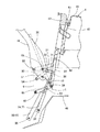
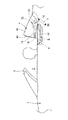
ここで、図4は、図7に示すコンバーチブルトップ10のクローズ状態におけるリンク構成を示している。図5は、図8に示すコンバーチブルトップ10のクローズ状態からオープン状態への作動の過渡期におけるリンク構成を示している。図6は、図9に示すコンバーチブルトップ10のオープン状態におけるリンク構成を示している。 Here, FIG. 4 shows a link configuration in the closed state of the convertible top 10 shown in FIG. FIG. 5 shows a link configuration in a transition period of operation from the closed state to the open state of the convertible top 10 shown in FIG. FIG. 6 shows a link configuration in the open state of the convertible top 10 shown in FIG.
図4〜図6において、符号16は、上記幌フレーム12の後端寄りに位置する上記リヤサイドフレームであって、このリヤサイドフレーム16は、枢支ピン51によって、車体内側部に固定配置されたベースプレート6に枢支され、車体前後方向へ回動自在とされている。
4 to 6,
また、このリヤサイドフレーム16の上記枢支ピン51bから適宜離間した位置には、支点ピン59によってリンク31の一端が連結されている。このリンク31の他端にはピン38によって第1シリンダユニット33の先端が連結されている。この第1シリンダユニット33は、特許請求の範囲中の「第1の駆動源X」に該当するものであって、その基端はピン36によって車体側に連結されている。さらに、上記リンク31の中間位置には、支点ピン58によってリンク32の一端が連結されるとともに、該リンク32の他端は枢支ピン54によって車体側の上記ベース体6に枢支されている。
Further, one end of the
従って、上記リヤサイドフレーム16は、上記第1シリンダユニット33の伸縮動によって作動する上記リンク31とリンク32を介して、上記枢支ピン51を中心として回動されることになる。
Therefore, the
図4〜図6において、符号17は、上記幌フレーム12の最後端に位置して上記幌11の後端縁を支持する後端ボウであって、この後端ボウ17の後方側の面にはシール材43が取付けられており、該後端ボウ17を介して上記シール材43が上記トノカバー4側のバックガラス42に衝合されることで、上記幌11の後端縁と上記バックガラス42の間のシール性が確保されている。
4 to 6,
上記後端ボウ17の下端部には、略L形に湾曲形成された支持アーム21の一端側が固定されている。この支持アーム21の他端は、支点ピン55によって、上記リヤサイドフレーム16における上記枢支ピン51の近傍位置に連結されている。
One end side of a
さらに、上記後端ボウ17の下端部には、コントロールアーム22の一端が支点ピン56によって回転可能に枢支されるとともに、該コントロールアーム22の他端は支点ピン39を介してサブリンク66の一端に連結されている。このサブリンク66の他端は支点ピン67を介して車体側に枢支されている。さらに、このサブリンク66の中間位置は、第2シリンダユニット34の先端部に連結されている。この第2シリンダユニット34は、特許請求の範囲中の「第2の駆動源Y」に該当するものであって、その基端部はピン37によって車体側に連結されている。
Further, one end of the
ここで、上記第2シリンダユニット34が伸長すると、上記サブリンク66が反時計方向へ回動し、上記コントロールアーム22が上方へ突き上げられ、このコントロールアーム22の突き上げに伴って上記後端ボウ17は上方へ押し上げられるが、それと同時に、該後端ボウ17は上記支持アーム21の回動によって上記支点ピン55を中心として上記リヤサイドフレーム16側へ引き付けられる。
Here, when the
これら両作用によって、上記ピン39は斜め上方へ移動することになるが、この実施形態では、図4に示すように上記リヤサイドフレーム16側の上記枢支ピン51を通る軌跡に沿って移動し、そのストロークエンドでは図5に示すように上記枢支ピン51に重合する位置に達するように、上記枢支ピン51と上記ピン37及び上記ピン39の三者間の相対位置が設定されている。
By these two actions, the
なお、図4〜図6において、符号20は、上記幌フレーム12の折曲・展開作動を制御するコントロールリンクであり、その一端は枢支ピン53によって上記ベース体6に枢支され、他端は上記幌フレーム12の上記第2ルーフサイドフレーム15の端部に連結されている(図7参照)。
II−2−b:作動の説明
(b−1) 上記コンバーチブルトップ10のクローズ状態
上記コンバーチブルトップ10がクローズ状態にあるときには、上記各部材は図4に示すような位置関係にある。即ち、上記リヤサイドフレーム16は立設状態にあり、伸長状態にある上記第1シリンダユニット33によって該リヤサイドフレーム16の立設状態が保持されている。
4 to 6,
II-2-b: Explanation of operation (b-1) Closed state of the convertible top 10 When the convertible top 10 is in the closed state, the respective members are in a positional relationship as shown in FIG. That is, the
また、上記第2シリンダユニット34は縮小状態にある。この場合、上記後端ボウ17は、上記第2シリンダユニット34に連結された上記サブリンク66及び上記コントロールアーム22によってその高さが規定されるとともに、この高さに対応して所定の傾動状態に姿勢保持された上記支持アーム21によってその傾動角度が規定されることから、この高さと傾動角度の規制によって、該後端ボウ17はその表面に設けた上記シール材43を介して、閉位置に設定された上記トノカバー4の前端面に位置する上記バックガラス42に衝合され、これら両者間のシール性が確保されている。
The
(b−2) 上記コンバーチブルトップ10のクローズ状態からオープン状態への作動時
上記コンバーチブルトップ10のクローズ状態からオープン状態への作動時には、先ず、図4に示した状態から上記第2シリンダユニット34を伸長させて上記後端ボウ17の姿勢変更を行なう。即ち、図4の状態において、先ず、上記第2シリンダユニット34を伸長させると、上記サブリンク66を介して上記コントロールアーム22が上記後端ボウ17及び上記支持アーム21と共に押し上げられ、最終的に、図5に示すように、上記コントロールアーム22の他端の上記ピン39が上記リヤサイドフレーム16側の上記枢支ピン51に重合される。
(B-2) When the convertible top 10 is operated from the closed state to the open state When the convertible top 10 is operated from the closed state to the open state, first, the
このような上記コントロールアーム22の押し上げに伴って、上記後端ボウ17は、該コントロールアーム22を介して上方へ突上げられるとともに、この突き上げ量に対応する角度だけ上記支点ピン55を中心として上記支持アーム21と一体的に回動する。
As the
この結果、図5に示すように、上記後端ボウ17は、上記リヤサイドフレーム16側へ引き寄せられて前傾姿勢とされ、上記トノカバー4の上記バックガラス42側から離間される。なお、この後端ボウ17の前傾姿勢は、上記支持アーム21とコントロールアーム22によって保持される。
As a result, as shown in FIG. 5, the
このように上記コンバーチブルトップ10が姿勢保持された状態で、上記トノカバー4を、上記トノカバー駆動シリンダ7によって閉位置から開位置側へ回動させて、これを開位置で保持させる(図8参照)。 In the state where the convertible top 10 is held in this manner, the tonneau cover 4 is rotated from the closed position to the open position side by the tonneau cover drive cylinder 7 and held in the open position (see FIG. 8). .
(b−3) 上記コンバーチブルトップ10のオープン状態への作動
図5に示す状態から、上記トノカバー4を開位置へ設定した後、上記第1シリンダユニット33を縮小作動させ、上記リヤサイドフレーム16をその上記枢支ピン51回りに後傾させる。この場合、上記枢支ピン51と上記コントロールアーム22側の上記ピン38が重合しているため、上記コントロールアーム22は見掛け上、上記枢支ピン51を中心として上記リヤサイドフレーム16及び上記支持アーム21との相対関係を維持したままこれらと一体的に後傾され、図6に示すように、リヤフロアパネル49の後部寄りの収納スペース8(図9参照)内に収納される。収納完了後、上記トノカバー4を開位置から閉位置へ回動させ、閉位置で保持する。
(B-3) Operation of the convertible top 10 to the open state After the tonneau cover 4 is set to the open position from the state shown in FIG. 5, the
以上で、上記コンバーチブルトップ10のクローズ状態からオープン状態への変更操作が完了する。
II−3:作用効果
以上のように構成された上記各実施形態に係る車両用コンバーチブルトップの駆動構造によれば、以下のような特有の作用効果が得られる。
(3−a) 上記各実施形態の駆動構造においては、上記第1の駆動源Xと第2の駆動源Yを共に車体側に配置され、上記幌フレーム12側には存在しないことから、
(3−a−1) 各駆動源X,Yによって車室内からの後方視界が妨げられることがなく、運転上の安全性が担保される、
(3−a−2) 車室2内の居住空間が十分に確保され、車室2内での快適性が向上する、
(3−a−3) 各駆動源X,Yと乗員の体との接触が可及的に防止されるとともに、該駆動源X,Yの運転音による不快感が低減され、車室2内での安全性と快適性が確保される、
(3−a−4) 可動部材である上記幌フレーム12の構造の簡略化及び軽量化が促進されるとともに、作動時の安定性が向上する、
等の効果が得られる。
(3−b) 上記第1の駆動源Xと第2の駆動源Yが共に車体側に配置され、且つ該各駆動源X,Yが支持アーム21及びコントロールアーム22を介して上記後端ボウ17を駆動させる構成であることから、これら各部材の配置スペースの確保が容易であり、その結果、駆動方式の選択の自由度及びレイアウトの自由度が拡大する事になる。
(3−c) 上記コントロールアーム22が上記サブリンク61,62,66を介して上記第2の駆動源Yにより駆動される構成であることから、該サブリンク61,62,66の作動領域分だけ上記コントロールアーム22と上記第2の駆動源Yの間隔を大きくとることができ、この結果、例えば、該第2の駆動源Yを車体側の余裕スペース部分に配置するなど、該第2の駆動源Yの車体側へのレイアウトの自由度が拡大されるという効果も得られる。
(3−d) 上記第1の実施形態のように、上記第1の駆動源Xと第2の駆動源Yを、共にモータユニット25、26で構成した場合には、該モータユニットの特性として、遠隔操作が容易であることから、上記各駆動源X,Yのレイアウトの自由度がさらに向上することになる。
(3−e) 上記第2の実施形態のように、上記第1の駆動源Xと第2の駆動源Yを、共にシリンダユニット33、34で構成した場合には、該シリンダユニット33、34の特性として、コンパクトな構成で大きな駆動力を発生し得ることから、駆動部分のコンパクト化が図れる。
Thus, the change operation of the convertible top 10 from the closed state to the open state is completed.
II-3: Operational Effects According to the vehicle convertible top drive structure according to each of the embodiments configured as described above, the following specific operational effects are obtained.
(3-a) In the drive structure of each of the above embodiments, the first drive source X and the second drive source Y are both arranged on the vehicle body side and do not exist on the
(3-a-1) The rear view from the passenger compartment is not obstructed by each drive source X, Y, and driving safety is ensured.
(3-a-2) The living space in the
(3-a-3) Contact between each drive source X, Y and the occupant's body is prevented as much as possible, and discomfort due to the driving sound of the drive source X, Y is reduced. To ensure safety and comfort in
(3-a-4) Simplification and weight reduction of the structure of the
Etc. are obtained.
(3-b) Both the first drive source X and the second drive source Y are disposed on the vehicle body side, and the drive sources X and Y are connected to the rear end bow via the
(3-c) Since the
(3-d) When the first drive source X and the second drive source Y are both configured by the
(3-e) When the first drive source X and the second drive source Y are both configured by the
1 ・・車両
2 ・・車室
3 ・・フロントヘッダ
4 ・・トノカバー
6 ・・ベースプレート
7 ・・トノカバー駆動シリンダ
8 ・・収納スペース
10 ・・コンバーチブルトップ
11 ・・幌
12 ・・幌フレーム
13 ・・フロントフレーム
14 ・・第1ルーフサイドフレーム
15 ・・第2ルーフサイドフレーム
16 ・・リヤサイドフレーム
17 ・・後端ボウ
18 ・・中間ボウ
19 ・・前側ボウ
20〜23 ・・リンク
20 ・・コントロールリンク
21 ・・支持アーム
22 ・・コントロールアーム
23 ・・第1セクター
24 ・・第2セクター
25 ・・第1モータユニット(第1の駆動源)
25A ・・モータ
26 ・・第2モータユニット(第2の駆動源)
26A ・・モータ
31 ・・リンク
32 ・・リンク
33 ・・第1シリンダユニット(第1の駆動源)
34 ・・第2シリンダユニット(第2の駆動源)
35〜39 ・・ピン
41 ・・カバー本体
42 ・・バックガラス
43 ・・シール材
49 ・・リヤフロアパネル
51〜54 ・・枢支ピン
55〜59 ・・支点ピン
61 ・・サブリンク
62 ・・サブリンク
63 ・・支点ピン
64 ・・枢支ピン
65 ・・枢支ピン
66 ・・第5リンク
67 ・・支点ピン
68 ・・枢支ピン
X ・・第1の駆動源
Y ・・第2の駆動源
1 ··
25A ..
26A ..
..Second cylinder unit (second drive source)
35 to 39 ··
Claims (4)
上記幌フレーム(12)の後端側に位置しその一端が枢支ピン(51)によって車体側に枢支され且つ車体側に配置された第1の駆動源(X)によって回動されるリヤサイドフレーム(16)と、
一端が上記後端ボウ(17)に固定される一方、他端が上記リヤサイドフレーム(16)の適所に相対回転可能に連結された支持アーム(21)と、
一端が上記後端ボウ(17)に支点ピン(56)によって相対回転可能に連結される一方、他端には支点ピン(57)によってサブリンク(61,62,66)が連結され該サブリンク(61,62,66)を介して車体側に配置された第2の駆動源(Y)によって駆動されるコントロールアーム(22)を備え、
上記コンバーチブルトップ(10)のクローズ状態からのオープン作動時には、上記第2の駆動源(Y)によって上記サブリンク(61,62,66)を介して上記コントロールアーム(22)を駆動して上記支点ピン(57)を上記リヤサイドフレーム(16)の上記枢支ピン(51)に重合する位置に位置させることで、上記後端ボウ(17)が上記トノカバー(4)の前面から離間して上記リヤサイドフレーム(16)寄りへ移動されるとともに、
上記第1の駆動源(X)によって上記リヤサイドフレーム(16)を、上記枢支ピン(51)を中心として車体後方側へ傾倒させるとき上記後端ボウ(17)が上記リヤサイドフレーム(16)との相対位置を維持したまま上記支点ピン(57)を中心として該リヤサイドフレーム(16)と一体的に傾倒されるように構成したことを特徴とする車両用コンバーチブルトップの駆動構造。 The hood (11) is supported by a hood frame (12) that can be folded and unfolded, and the hood frame (12) is opened and closed to open and close the upper part of the passenger compartment (2). On the rear side of (12) is a rear end bow (17) which is openable and closable and in the closed position and at the rear end of the hood frame (12). In the convertible top for a vehicle (10) provided with a tonneau cover (4) which is brought into contact with the front side,
A rear side located on the rear end side of the hood frame (12), one end of which is pivotally supported on the vehicle body side by a pivot pin (51) and rotated by a first drive source (X) disposed on the vehicle body side. Frame (16);
A support arm (21) having one end fixed to the rear end bow (17) and the other end connected to an appropriate position of the rear side frame (16) in a relatively rotatable manner;
One end is connected to the rear end bow (17) by a fulcrum pin (56) so as to be relatively rotatable, and the other end is connected to a sublink (61, 62, 66) by a fulcrum pin (57). A control arm (22) driven by a second drive source (Y) disposed on the vehicle body side via (61, 62, 66),
When the convertible top (10) is opened from the closed state, the control arm (22) is driven by the second drive source (Y) via the sublinks (61, 62, 66) to thereby support the fulcrum. The rear end bow (17) is separated from the front surface of the tonneau cover (4) by positioning the pin (57) at a position where it overlaps the pivot pin (51) of the rear side frame (16). Moved towards the frame (16),
When the first drive source (X) tilts the rear side frame (16) toward the rear side of the vehicle body around the pivot pin (51), the rear end bow (17) is connected to the rear side frame (16). A drive structure for a convertible top for a vehicle, characterized in that it is tilted integrally with the rear side frame (16) with the fulcrum pin (57) as the center while maintaining the relative position of the vehicle.
上記第1の駆動源(X)と第2の駆動源(Y)が、共にモータユニット(25)、(26)で構成されていることを特徴とする車両用コンバーチブルトップの駆動構造。 In claim 1,
A drive structure for a convertible top for a vehicle, wherein the first drive source (X) and the second drive source (Y) are both composed of motor units (25) and (26).
上記各モータユニット(25)、(26)は、共にセクター(23)、(24)を介して上記リヤサイドフレーム(16)及び上記コントロールアーム(22)を駆動する構成であることを特徴とする車両用コンバーチブルトップの駆動構造。 In claim 2,
Each of the motor units (25), (26) is configured to drive the rear side frame (16) and the control arm (22) via sectors (23), (24). Convertible top drive structure.
上記第1の駆動源(X)と第2の駆動源(Y)が、共にシリンダユニット(33、34)で構成されていることを特徴とする車両用コンバーチブルトップの駆動構造。 In claim 1,
A drive structure for a convertible top for a vehicle, wherein the first drive source (X) and the second drive source (Y) are both composed of cylinder units (33, 34).
Priority Applications (1)
| Application Number | Priority Date | Filing Date | Title |
|---|---|---|---|
| JP2008170923A JP5159472B2 (en) | 2008-06-30 | 2008-06-30 | Drive structure for convertible top for vehicles |
Applications Claiming Priority (1)
| Application Number | Priority Date | Filing Date | Title |
|---|---|---|---|
| JP2008170923A JP5159472B2 (en) | 2008-06-30 | 2008-06-30 | Drive structure for convertible top for vehicles |
Publications (2)
| Publication Number | Publication Date |
|---|---|
| JP2010006331A true JP2010006331A (en) | 2010-01-14 |
| JP5159472B2 JP5159472B2 (en) | 2013-03-06 |
Family
ID=41587306
Family Applications (1)
| Application Number | Title | Priority Date | Filing Date |
|---|---|---|---|
| JP2008170923A Expired - Fee Related JP5159472B2 (en) | 2008-06-30 | 2008-06-30 | Drive structure for convertible top for vehicles |
Country Status (1)
| Country | Link |
|---|---|
| JP (1) | JP5159472B2 (en) |
Cited By (1)
| Publication number | Priority date | Publication date | Assignee | Title |
|---|---|---|---|---|
| EP3151046A1 (en) | 2010-01-14 | 2017-04-05 | Fujikura Ltd. | Optical fiber connector, optical fiber connector assembling method, pin clamp |
Citations (3)
| Publication number | Priority date | Publication date | Assignee | Title |
|---|---|---|---|---|
| US5816644A (en) * | 1995-06-22 | 1998-10-06 | Wilhelm Karmann Gmbh | Folding top for a convertible |
| WO2007062109A1 (en) * | 2005-11-23 | 2007-05-31 | Wilhelm Karmann Gmbh | Convertible top having overcenter linkage |
| JP2010006330A (en) * | 2008-06-30 | 2010-01-14 | Toyo Seat Co Ltd | Vehicular convertible top driving structure |
-
2008
- 2008-06-30 JP JP2008170923A patent/JP5159472B2/en not_active Expired - Fee Related
Patent Citations (3)
| Publication number | Priority date | Publication date | Assignee | Title |
|---|---|---|---|---|
| US5816644A (en) * | 1995-06-22 | 1998-10-06 | Wilhelm Karmann Gmbh | Folding top for a convertible |
| WO2007062109A1 (en) * | 2005-11-23 | 2007-05-31 | Wilhelm Karmann Gmbh | Convertible top having overcenter linkage |
| JP2010006330A (en) * | 2008-06-30 | 2010-01-14 | Toyo Seat Co Ltd | Vehicular convertible top driving structure |
Cited By (1)
| Publication number | Priority date | Publication date | Assignee | Title |
|---|---|---|---|---|
| EP3151046A1 (en) | 2010-01-14 | 2017-04-05 | Fujikura Ltd. | Optical fiber connector, optical fiber connector assembling method, pin clamp |
Also Published As
| Publication number | Publication date |
|---|---|
| JP5159472B2 (en) | 2013-03-06 |
Similar Documents
| Publication | Publication Date | Title |
|---|---|---|
| JP5047522B2 (en) | Retractable roof and vehicle equipped with the same | |
| JP4766785B2 (en) | Convertible vehicle roof | |
| JP3771877B2 (en) | Cover device for roof mechanism storage | |
| JP4827503B2 (en) | Roof housing mechanism for automobile and automobile equipped with the same | |
| JP6622647B2 (en) | Electric sunshade sunroof structure | |
| JP3885607B2 (en) | Vehicle roof structure | |
| JP4790465B2 (en) | Retractable roof and vehicle equipped with the same | |
| JP2003237375A (en) | Cabriolet automobile with foldable hard top | |
| JPH10175448A (en) | Roof construction of cabriolet type passenger car | |
| US6659533B1 (en) | Vehicle convertible roof | |
| US6796595B2 (en) | Vehicle convertible roof | |
| JP4803409B2 (en) | The movable roof part of the openable vehicle roof | |
| US20160089965A1 (en) | Rear vehicle-body structure of vehicle | |
| JP2009523089A (en) | Car folding roof | |
| JP5159472B2 (en) | Drive structure for convertible top for vehicles | |
| CN108136882A (en) | The rear structure of vehicle | |
| JP5028347B2 (en) | Drive structure for convertible top for vehicles | |
| JP5454211B2 (en) | Wheelchair lift device | |
| JP2009018792A (en) | Movable roof for passenger car | |
| JP2008137601A (en) | Roof storage type vehicle | |
| JP2005515112A (en) | Control device for automobile rear panel | |
| JP4958479B2 (en) | Retractable roof and vehicle equipped with the same | |
| WO2007114148A1 (en) | Retractable roof and vehicle with the same | |
| JP2008126987A (en) | Convertible top of automobile | |
| JP2008132799A (en) | Convertible top for automobile |
Legal Events
| Date | Code | Title | Description |
|---|---|---|---|
| A621 | Written request for application examination |
Free format text: JAPANESE INTERMEDIATE CODE: A621 Effective date: 20110628 |
|
| A521 | Written amendment |
Free format text: JAPANESE INTERMEDIATE CODE: A523 Effective date: 20110801 |
|
| RD02 | Notification of acceptance of power of attorney |
Free format text: JAPANESE INTERMEDIATE CODE: A7422 Effective date: 20120210 |
|
| TRDD | Decision of grant or rejection written | ||
| A977 | Report on retrieval |
Free format text: JAPANESE INTERMEDIATE CODE: A971007 Effective date: 20121122 |
|
| A01 | Written decision to grant a patent or to grant a registration (utility model) |
Free format text: JAPANESE INTERMEDIATE CODE: A01 Effective date: 20121127 |
|
| A61 | First payment of annual fees (during grant procedure) |
Free format text: JAPANESE INTERMEDIATE CODE: A61 Effective date: 20121211 |
|
| R150 | Certificate of patent or registration of utility model |
Ref document number: 5159472 Country of ref document: JP Free format text: JAPANESE INTERMEDIATE CODE: R150 Free format text: JAPANESE INTERMEDIATE CODE: R150 |
|
| FPAY | Renewal fee payment (event date is renewal date of database) |
Free format text: PAYMENT UNTIL: 20151221 Year of fee payment: 3 |
|
| R250 | Receipt of annual fees |
Free format text: JAPANESE INTERMEDIATE CODE: R250 |
|
| R250 | Receipt of annual fees |
Free format text: JAPANESE INTERMEDIATE CODE: R250 |
|
| R250 | Receipt of annual fees |
Free format text: JAPANESE INTERMEDIATE CODE: R250 |
|
| R250 | Receipt of annual fees |
Free format text: JAPANESE INTERMEDIATE CODE: R250 |
|
| LAPS | Cancellation because of no payment of annual fees |