JP2010005986A - Method of molding green tire - Google Patents
Method of molding green tire Download PDFInfo
- Publication number
- JP2010005986A JP2010005986A JP2008170148A JP2008170148A JP2010005986A JP 2010005986 A JP2010005986 A JP 2010005986A JP 2008170148 A JP2008170148 A JP 2008170148A JP 2008170148 A JP2008170148 A JP 2008170148A JP 2010005986 A JP2010005986 A JP 2010005986A
- Authority
- JP
- Japan
- Prior art keywords
- mold
- inner liner
- rubber sheet
- winding
- laminate
- Prior art date
- Legal status (The legal status is an assumption and is not a legal conclusion. Google has not performed a legal analysis and makes no representation as to the accuracy of the status listed.)
- Granted
Links
Images


Classifications
-
- B—PERFORMING OPERATIONS; TRANSPORTING
- B29—WORKING OF PLASTICS; WORKING OF SUBSTANCES IN A PLASTIC STATE IN GENERAL
- B29D—PRODUCING PARTICULAR ARTICLES FROM PLASTICS OR FROM SUBSTANCES IN A PLASTIC STATE
- B29D30/00—Producing pneumatic or solid tyres or parts thereof
- B29D30/06—Pneumatic tyres or parts thereof (e.g. produced by casting, moulding, compression moulding, injection moulding, centrifugal casting)
- B29D30/08—Building tyres
- B29D30/20—Building tyres by the flat-tyre method, i.e. building on cylindrical drums
- B29D30/30—Applying the layers; Guiding or stretching the layers during application
- B29D30/3007—Applying the layers; Guiding or stretching the layers during application by feeding a sheet perpendicular to the drum axis and joining the ends to form an annular element
-
- B—PERFORMING OPERATIONS; TRANSPORTING
- B29—WORKING OF PLASTICS; WORKING OF SUBSTANCES IN A PLASTIC STATE IN GENERAL
- B29D—PRODUCING PARTICULAR ARTICLES FROM PLASTICS OR FROM SUBSTANCES IN A PLASTIC STATE
- B29D30/00—Producing pneumatic or solid tyres or parts thereof
- B29D30/06—Pneumatic tyres or parts thereof (e.g. produced by casting, moulding, compression moulding, injection moulding, centrifugal casting)
- B29D30/0681—Parts of pneumatic tyres; accessories, auxiliary operations
-
- B—PERFORMING OPERATIONS; TRANSPORTING
- B32—LAYERED PRODUCTS
- B32B—LAYERED PRODUCTS, i.e. PRODUCTS BUILT-UP OF STRATA OF FLAT OR NON-FLAT, e.g. CELLULAR OR HONEYCOMB, FORM
- B32B1/00—Layered products having a general shape other than plane
- B32B1/08—Tubular products
-
- B—PERFORMING OPERATIONS; TRANSPORTING
- B32—LAYERED PRODUCTS
- B32B—LAYERED PRODUCTS, i.e. PRODUCTS BUILT-UP OF STRATA OF FLAT OR NON-FLAT, e.g. CELLULAR OR HONEYCOMB, FORM
- B32B25/00—Layered products comprising a layer of natural or synthetic rubber
- B32B25/04—Layered products comprising a layer of natural or synthetic rubber comprising rubber as the main or only constituent of a layer, which is next to another layer of the same or of a different material
- B32B25/08—Layered products comprising a layer of natural or synthetic rubber comprising rubber as the main or only constituent of a layer, which is next to another layer of the same or of a different material of synthetic resin
-
- B—PERFORMING OPERATIONS; TRANSPORTING
- B32—LAYERED PRODUCTS
- B32B—LAYERED PRODUCTS, i.e. PRODUCTS BUILT-UP OF STRATA OF FLAT OR NON-FLAT, e.g. CELLULAR OR HONEYCOMB, FORM
- B32B7/00—Layered products characterised by the relation between layers; Layered products characterised by the relative orientation of features between layers, or by the relative values of a measurable parameter between layers, i.e. products comprising layers having different physical, chemical or physicochemical properties; Layered products characterised by the interconnection of layers
- B32B7/04—Interconnection of layers
- B32B7/12—Interconnection of layers using interposed adhesives or interposed materials with bonding properties
-
- B—PERFORMING OPERATIONS; TRANSPORTING
- B60—VEHICLES IN GENERAL
- B60C—VEHICLE TYRES; TYRE INFLATION; TYRE CHANGING; CONNECTING VALVES TO INFLATABLE ELASTIC BODIES IN GENERAL; DEVICES OR ARRANGEMENTS RELATED TO TYRES
- B60C1/00—Tyres characterised by the chemical composition or the physical arrangement or mixture of the composition
- B60C1/0008—Compositions of the inner liner
-
- B—PERFORMING OPERATIONS; TRANSPORTING
- B60—VEHICLES IN GENERAL
- B60C—VEHICLE TYRES; TYRE INFLATION; TYRE CHANGING; CONNECTING VALVES TO INFLATABLE ELASTIC BODIES IN GENERAL; DEVICES OR ARRANGEMENTS RELATED TO TYRES
- B60C5/00—Inflatable pneumatic tyres or inner tubes
- B60C5/12—Inflatable pneumatic tyres or inner tubes without separate inflatable inserts, e.g. tubeless tyres with transverse section open to the rim
- B60C5/14—Inflatable pneumatic tyres or inner tubes without separate inflatable inserts, e.g. tubeless tyres with transverse section open to the rim with impervious liner or coating on the inner wall of the tyre
-
- B—PERFORMING OPERATIONS; TRANSPORTING
- B29—WORKING OF PLASTICS; WORKING OF SUBSTANCES IN A PLASTIC STATE IN GENERAL
- B29D—PRODUCING PARTICULAR ARTICLES FROM PLASTICS OR FROM SUBSTANCES IN A PLASTIC STATE
- B29D30/00—Producing pneumatic or solid tyres or parts thereof
- B29D30/06—Pneumatic tyres or parts thereof (e.g. produced by casting, moulding, compression moulding, injection moulding, centrifugal casting)
- B29D30/0681—Parts of pneumatic tyres; accessories, auxiliary operations
- B29D2030/0682—Inner liners
-
- B—PERFORMING OPERATIONS; TRANSPORTING
- B32—LAYERED PRODUCTS
- B32B—LAYERED PRODUCTS, i.e. PRODUCTS BUILT-UP OF STRATA OF FLAT OR NON-FLAT, e.g. CELLULAR OR HONEYCOMB, FORM
- B32B2307/00—Properties of the layers or laminate
- B32B2307/70—Other properties
- B32B2307/724—Permeability to gases, adsorption
- B32B2307/7242—Non-permeable
-
- B—PERFORMING OPERATIONS; TRANSPORTING
- B60—VEHICLES IN GENERAL
- B60C—VEHICLE TYRES; TYRE INFLATION; TYRE CHANGING; CONNECTING VALVES TO INFLATABLE ELASTIC BODIES IN GENERAL; DEVICES OR ARRANGEMENTS RELATED TO TYRES
- B60C5/00—Inflatable pneumatic tyres or inner tubes
- B60C5/12—Inflatable pneumatic tyres or inner tubes without separate inflatable inserts, e.g. tubeless tyres with transverse section open to the rim
- B60C5/14—Inflatable pneumatic tyres or inner tubes without separate inflatable inserts, e.g. tubeless tyres with transverse section open to the rim with impervious liner or coating on the inner wall of the tyre
- B60C2005/145—Inflatable pneumatic tyres or inner tubes without separate inflatable inserts, e.g. tubeless tyres with transverse section open to the rim with impervious liner or coating on the inner wall of the tyre made of laminated layers
-
- B—PERFORMING OPERATIONS; TRANSPORTING
- B60—VEHICLES IN GENERAL
- B60C—VEHICLE TYRES; TYRE INFLATION; TYRE CHANGING; CONNECTING VALVES TO INFLATABLE ELASTIC BODIES IN GENERAL; DEVICES OR ARRANGEMENTS RELATED TO TYRES
- B60C5/00—Inflatable pneumatic tyres or inner tubes
- B60C5/12—Inflatable pneumatic tyres or inner tubes without separate inflatable inserts, e.g. tubeless tyres with transverse section open to the rim
- B60C5/14—Inflatable pneumatic tyres or inner tubes without separate inflatable inserts, e.g. tubeless tyres with transverse section open to the rim with impervious liner or coating on the inner wall of the tyre
- B60C2005/147—Inflatable pneumatic tyres or inner tubes without separate inflatable inserts, e.g. tubeless tyres with transverse section open to the rim with impervious liner or coating on the inner wall of the tyre characterised by the joint or splice
Abstract
Description
この発明は、生タイヤの成型方法、なかでも、多くは熱可塑性樹脂材料からなるガスバリア性の薄膜状フィルムインナーライナを、製品タイヤのインナーライナとするタイヤを製造するためのグリーンタイヤの成型方法に関するものであり、とくには、薄膜状のフィルムインナーライナを、成型型に対し、所定の位置に常に適正に、かつ簡易・迅速に巻付け配置する技術を提案するものである。 The present invention relates to a green tire molding method, and more particularly to a green tire molding method for manufacturing a tire using a gas barrier thin film film inner liner made of a thermoplastic resin material as an inner liner of a product tire. In particular, the present invention proposes a technique in which a thin film inner liner is wound appropriately and simply and quickly at a predetermined position on a mold.
タイヤの内面に適用されて空気透過防止層として機能するインナーライナとしては、ブチルゴムを主成分とするゴム層が従来から広く一般に使用されていたが、近年に到っては、タイヤの軽量化等を目的として、たとえば特許文献1に開示されているように、インナーライナを、ガスバリア性の薄膜状の熱可塑性樹脂フィルムにて形成することが提案されている。
As an inner liner that is applied to the inner surface of a tire and functions as an air permeation preventive layer, a rubber layer mainly composed of butyl rubber has been widely used in the past, but in recent years, the weight of the tire has been reduced, etc. For this purpose, for example, as disclosed in
しかるに、平坦な形態を有する帯状の熱可塑性樹脂フィルムを成型型の周りに巻付けてインナーライナ素材を形成するときは、周上の一個所以上にその熱可塑性樹脂フィルムの接合部が生じることになって、その接合部からの空気漏れのおそれがあることから、特許文献2には、インナーライナ素材を形成する熱可塑性樹脂フィルムを接合部のない円筒形状に成形する技術が提案されている。
However, when a belt-shaped thermoplastic resin film having a flat shape is wound around a mold to form an inner liner material, a joining portion of the thermoplastic resin film is generated at one or more locations on the circumference. Thus, since there is a risk of air leakage from the joint portion,
ところで、インナーライナ素材を形成する熱可塑性樹脂フィルムを、接合部のない円筒形状に予め成形する場合は、成型される生タイヤの周長に応じた各種の円筒寸法の熱可塑性樹脂フィルムを予め準備することが必要になるため、円筒形状熱可塑性樹脂フィルムのコストの増加が否めない他、多数種類のフィルムの在庫が不可避となって、在庫管理コスト等の増加に加え、生産能率の低下が余儀なくされるという他の問題があった。 By the way, when the thermoplastic resin film that forms the inner liner material is pre-formed into a cylindrical shape without a joint, a thermoplastic resin film having various cylindrical dimensions corresponding to the circumference of the green tire to be molded is prepared in advance. In addition to inevitably increasing the cost of the cylindrical thermoplastic film, it is inevitable that many types of film are in stock, and in addition to an increase in inventory management costs, production efficiency is inevitably reduced. There was another problem of being.
このような問題点を解決してなお、帯状をなす薄肉の樹脂フィルムの取り扱いを容易にして、その樹脂フィルムを、成型型の周りにそれの全周にわたって、適正にかつ、簡易・迅速に巻付ける従来技術としては、特許文献3に記載されているように、少なくとも樹脂フィルム層を含む層とゴム状弾性体層とを、接着剤層を介して接合させてなる積層体の一方の端部に、あらかじめ作製した他の接着剤層を転写積層し、該積層体の他方の端部を、他の接着剤層に重ね合わせ貼合わせて得た円管体をタイヤ用部材として用いる技術がある。
After solving these problems, it is easy to handle a thin resin film in the form of a strip, and the resin film is wound around the mold properly and simply and quickly around the entire circumference. As a conventional technique to be applied, as described in
これによれば、薄肉の樹脂フィルム層を含む層を、ゴム状弾性体層によって裏打ちすることで、薄肉樹脂フィルム層を含む層の取り扱いを容易にして、その積層体の成型型への巻付けを、すぐれた作業性の下で行うことができるので、生タイヤの成型作業能率が向上することになり、また、積層体の他方の端部を、他の接着剤層を介して一方の端部に重ね合わせて貼合させることで、樹脂フィルム層を含む層の重ね合わせ接合部の意図しない剥離等のおそれを有利に取り除くことができ、そして、多数種類の樹脂フィルムの在庫および在庫管理を不要にできるという利点がある。
しかるに特許文献3に記載された従来技術では、積層体の一方の端部上への、他方の端部の貼合に当っては、その貼合に際して、または事前に、他の接着剤層を、積層体のいずれか一方の端部に転写積層することが必要になるという作業工程上および、接着剤の使用量の上での問題があった他、積層体の、樹脂フィルム層を含む層を内面側とした成型型周面上への巻付けの開始に当って、積層体の巻付け始端を、成型型の周面上の所定の位置に確実に位置決め配置することが難しいという問題があった。
However, in the prior art described in
この発明は、従来技術が抱えるこのような問題点を解決することを課題としてなされたものであり、それの目的とするところは、たとえば、熱可塑性樹脂フィルムの単層もしくは積層構造になる、ガスバリア性の薄膜状フィルムインナーライナの取り扱いを容易にすることはもちろん、そのフィルムインナーライナとゴムシートとの積層体の、成型型の周面への巻付け始端部分と巻付け終端部分との接合のための特別の接着剤層の塗布、転写積層等を不要として、作業工程数および、接着剤の使用量の増加を有効に防止し、併せて、積層体の巻付け始端の、成型型周面上への所定の位置決め配置を十分簡易なものとした生タイヤの成型方法を提供するにある。 The present invention has been made to solve such problems of the prior art, and the object of the present invention is, for example, a gas barrier that has a single-layer or laminated structure of a thermoplastic resin film. As well as facilitating the handling of the thin film film inner liner, the laminate of the film inner liner and the rubber sheet can be used to join the winding start end portion and winding end portion to the peripheral surface of the mold. This eliminates the need for special adhesive layer application, transfer lamination, etc., effectively preventing an increase in the number of work steps and the amount of adhesive used, and at the same time, the mold peripheral surface at the winding start of the laminate An object of the present invention is to provide a green tire molding method in which a predetermined positioning arrangement on the top is sufficiently simple.
この発明の生タイヤの成型方法は、たとえば、ともに幅を揃えた、ガスバリア性の薄膜状フィルムインナーライナと、未加硫隣接ゴムシートとを、それらのそれぞれの、長さ方向の各端縁位置を、それらの延在方向に相互にずらした状態で、前記フィルムインナーライナが有する接着剤層の介在下で貼着させてなる積層体の一本もしくは複数本を、成型型の全周にわたって、それの周方向に巻付けるに当り、端縁がそのフィルムインナーライナから突出して位置する未加硫隣接ゴムシートのその突出部分を、積層体の、成型型への巻付け始端部分の一部とし、その突出部分を成型型の表面に、直接的もしくは間接的に粘着させた状態で積層体の巻付けを開始し、積層体の、成型型に対する巻付け終端部分を、同一のまたは、他の積層体の巻付け始端部分の内周側へ入れ込んで、薄膜状フィルムインナーライナの端部分どうし、および、未加硫隣接ゴムシートの端部分どうしのそれぞれを、成型型の周方向に間隔をおいた位置で直接的に、重ね合わせもしくは突き合わせ接合させるにある。
なおこの成型方法は、薄膜状フィルムインナーライナと未加硫ゴムシートとの幅が揃わない場合をも可とするものである。
The raw tire molding method according to the present invention includes, for example, a gas barrier thin film film inner liner and an unvulcanized adjacent rubber sheet, both of which have the same width, and their respective edge positions in the length direction. In a state where they are shifted from each other in the extending direction, one or a plurality of laminates that are stuck under the adhesive layer of the film inner liner, over the entire circumference of the mold, When winding it in the circumferential direction, the protruding portion of the unvulcanized adjacent rubber sheet, the edge of which protrudes from the film inner liner, is defined as a part of the winding start end portion of the laminate on the mold. The winding of the laminate is started with the protruding portion directly or indirectly adhered to the surface of the mold, and the winding end portion of the laminate with respect to the mold is the same or other Laminate winding Insert into the inner peripheral side of the start end, and directly connect the end portions of the thin film inner liner and the end portions of the unvulcanized adjacent rubber sheet at positions spaced in the circumferential direction of the mold. In particular, it is in superposition or butt joining.
This molding method is also possible when the width of the thin film inner liner and the unvulcanized rubber sheet are not uniform.
この場合、フィルムインナーライナの端部分どうしの直接的な重ね合わせ接合は、そのフィルムインナーライナを未加硫隣接ゴムシートに貼着させるべくフィルムインナーライナに形成した、巻付け終端部分側の接着剤層上に、巻付け始端部分側を接合させることによって行うことができる。 In this case, the direct overlap bonding between the end portions of the film inner liner is an adhesive on the winding end portion side formed on the film inner liner so that the film inner liner is adhered to the unvulcanized adjacent rubber sheet. It can be performed by joining the winding start end portion side on the layer.
そして、未加硫隣接ゴムシートの端部分どうしの重ね合わせ接合は、そのゴムシートに固有の粘着力の下で、未加硫隣接ゴムシートの巻付け終端部分上に、巻付け始端側の前記突出部分を接合させることによって、また、突き合わせ接合は、これもまた、ゴムシートに固有の粘着力の下で、始終のそれぞれの端面を相互に接合させることによってそれぞれ行うことができる。 Then, the overlapping joining of the end portions of the unvulcanized adjacent rubber sheet is performed on the winding end portion side of the unvulcanized adjacent rubber sheet under the adhesive force inherent to the rubber sheet. By joining the protruding portions, butt joining can also be performed by joining the respective end faces of the beginning and end to each other under the adhesive force inherent to the rubber sheet.
なおここで、ガスバリア性の薄膜状フィルムインナーライナは、熱可塑性樹脂フィルムの単層もしくは積層構造体の、ゴムシートとの積層面側に、たとえばその全面にわたって接着剤層を付加したものとすることができ、そのフィルムインナーライナの樹脂材料は、より具体的には、エチレン−ビニルアルコール共重合体を反応させて得られる変性エチレン−ビニルアルコール共重合体からなるマトリックス中に、23℃におけるヤング率が前記変性エチレン−ビニルアルコール共重合体より小さい柔軟樹脂を分散させた樹脂組成物からなる層を少なくとも含むものとすることが好ましく、また、前記樹脂組成物からなる層に隣接して、更にエラストマーからなる補助層を一層以上具えるものとすること、前記樹脂組成物からなる層の厚さを100μm以下とすること、前記樹脂組成物からなる層と補助層との間、及び前記補助層と補助層との間の少なくとも一箇所に、一層以上の接着剤層を具えるものとすることが好ましい。 Here, the gas barrier thin film film inner liner is obtained by adding an adhesive layer, for example, over the entire surface of the single layer or laminated structure of the thermoplastic resin film to the rubber sheet. More specifically, the resin material of the film inner liner has a Young's modulus at 23 ° C. in a matrix composed of a modified ethylene-vinyl alcohol copolymer obtained by reacting an ethylene-vinyl alcohol copolymer. Preferably comprises at least a layer made of a resin composition in which a soft resin smaller than the modified ethylene-vinyl alcohol copolymer is dispersed, and further made of an elastomer adjacent to the layer made of the resin composition. Provide one or more auxiliary layers, the thickness of the layer composed of the resin composition It shall be 00 μm or less, and shall have one or more adhesive layers in at least one place between the layer made of the resin composition and the auxiliary layer and between the auxiliary layer and the auxiliary layer. preferable.
ここにおいて、このような薄膜状フィルムインナーライナに付加されて、主には、未加硫隣接ゴムシートとの貼着を司る接着剤層としては、ゴム成分100質量部に対し、分子中に反応部位を二つ以上有するマレイミド誘導体及びポリ―p―ジニトロソベンゼンの少なくとも一種を0.1質量部以上配合した接着剤組成物を用いることが好ましい。 Here, as an adhesive layer which is added to such a thin film inner liner and mainly administers adhesion to an unvulcanized adjacent rubber sheet, it reacts in the molecule with respect to 100 parts by mass of the rubber component. It is preferable to use an adhesive composition in which at least one part of at least one of a maleimide derivative having two or more sites and poly-p-dinitrosobenzene is blended.
ところで、薄膜状フィルムインナーライナと未加硫隣接ゴムシートとからなる積層体の複数本を、成型型の周りに、それの全周にわたって順次に巻付けるに当っては、一本の積層体の巻付け始端部分の一部としての前記突出部分を成型型の表面に直接的に貼着させる一方、他の積層体の巻付け始端部分の一部としての前記突出部分を、先に、成型型の周方向に向けて巻付けた積層体の巻付け終端部分を介して成型型の表面に間接的に粘着させて、一本の積層体の巻付け終端部分の薄膜状フィルムインナーライナおよび未加硫隣接ゴムシートのそれぞれの端部分に対し、他の積層体の巻付け始端部分の薄膜状フィルムインナーライナおよび未加硫隣接ゴムシートのそれぞれの端部分を、成型型の周方向に間隔をおいた位置で直接的に、重ね合わせもしくは突き合わせ接合させることが、一本の積層体を、成型型の全周にわたって巻付ける場合との、接合構造上の差異を少なくする上で好ましい。
なお、ここにおいてもまた、フィルムインナーライナの端部分どうしの直接的な接合は、そのインナーライナの、巻付け終端部分側の接着剤層上に、巻付け始端部分側を重ね合わせることによって行うことができる。
By the way, when winding a plurality of laminates composed of a thin film inner liner and an unvulcanized adjacent rubber sheet sequentially around the entire circumference of the mold, The projecting part as a part of the winding start end part is directly attached to the surface of the mold, while the projecting part as a part of the winding start end part of the other laminate is first molded. The thin film-like film inner liner at the winding end portion of one laminate and the non-added film are adhered to the surface of the mold indirectly through the winding end portion of the laminate wound in the circumferential direction. For each end portion of the adjacent rubber sheet, the thin film-like film inner liner at the winding start end portion of the other laminate and each end portion of the unvulcanized adjacent rubber sheet are spaced apart in the circumferential direction of the mold. Directly overlaid Or butt be joined is preferable for the one of the laminate, and when winding over the entire circumference of the mold, to reduce the differences in junction structure.
Here again, the end portions of the film inner liner are directly joined to each other by superimposing the winding start end portion side on the adhesive layer on the winding end portion side of the inner liner. Can do.
この場合、未加硫隣接ゴムシートは、薄膜状フィルムインナーライナの、成型型への巻付けの容易性等を担保するためだけのものとすることもできるが、そのフィルムインナーライナに隣接させて配置されて、タイヤの機能部材としても作用することになる、インナーライナ用ゴムシート、スキージゴム用ゴムシートもしくは、カーカスプライ用コードを埋設したゴムシートとすることが好ましい。 In this case, the unvulcanized adjacent rubber sheet can be used only for ensuring the ease of winding of the thin film-like film inner liner on the mold, etc., but it is adjacent to the film inner liner. Preferably, the rubber sheet is a rubber sheet with an inner liner rubber sheet, a squeegee rubber sheet, or a carcass ply cord embedded therein, which also functions as a functional member of the tire.
また好ましくは、同一の積層体内での、または、異なった積層体間での、未加硫ゴムシートの端部分どうしの接合域および、薄膜状フィルムインナーライナの端部分どうしの接合域のそれぞれの、成型型の周方向の長さを0〜20mmおよび、0〜60mmの範囲とし、そしてまた、それらのそれぞれの接合域の、成型型の周方向の離隔距離は、0〜60mmの範囲とすることが好ましい。 Preferably, each of the joining region between the end portions of the unvulcanized rubber sheet and the joining region between the end portions of the thin film inner liner in the same laminate or between different laminates. The circumferential length of the mold is in the range of 0 to 20 mm and 0 to 60 mm, and the separation distance in the circumferential direction of the mold in their respective joining areas is in the range of 0 to 60 mm. It is preferable.
この発明の成型方法では、相互に貼着された、薄膜状フィルムインナーライナと未加硫隣接ゴムシートとからなる積層体の巻付け始端部分で、薄膜状フィルムインナーライナの端縁より突出して位置する未加硫隣接ゴムシートの突出部分を、そのフィルムインナーライナを内側に向けた姿勢として成型型の周面に粘着させて、その成型型の周りに積層体を巻付けることにより、薄膜状フィルムインナーライナの取り扱いを、未加硫隣接ゴムシートの裏打ちの下で、簡単かつ容易なものとして、フィルムインナーライナの成型型への所要の巻付けを、すぐれた作業性の下で、能率良く行うことができる。 In the molding method of the present invention, at the winding start end portion of the laminated body composed of the thin film-like film inner liner and the unvulcanized adjacent rubber sheet that are adhered to each other, the protrusion protrudes from the edge of the thin film-like film inner liner. By sticking the protruding part of the unvulcanized adjacent rubber sheet to the peripheral surface of the mold with the film inner liner facing inward, and winding the laminate around the mold, a thin film film The inner liner is handled easily and easily under the backing of an unvulcanized adjacent rubber sheet, and the required winding around the mold of the film inner liner is performed efficiently and with excellent workability. be able to.
そしてこの場合は、未加硫隣接ゴムシートの、フィルムインナーライナからの突出部分を成型型に粘着させることで、積層体、ひいては、薄膜状フィルムインナーライナの巻付け始端の、成型型周面上の所定位置への位置決め配置を十分簡易なものとするとともに、すぐれた位置決め精度を実現することができる。 And in this case, by sticking the protruding portion of the unvulcanized adjacent rubber sheet from the film inner liner to the mold, the laminate, and eventually the winding start of the thin film inner liner, on the mold peripheral surface The positioning and positioning at a predetermined position can be made simple enough, and excellent positioning accuracy can be realized.
さらにこの方法では、積層体の、成型型に対する巻付け終端部分を、同一のまたは、他の積層体の、成型型周面に予め粘着されている巻付け始端部分の内周側に入れ込んで、そこで、薄膜状フィルムインナーライナの端部分どうし、および、未加硫隣接ゴムシートの端部分どうしのそれぞれを、成型型の周方向に間隔をおいた位置で、たとえば直接的に重ね合わせ接合させることで、フィルムインナーライナどうしは、それの、隣接ゴムシート側に予め設けた接着剤層によって、そして、隣接ゴムシートどうしは、ゴムシートそれ自身の粘着力によって接合させることができるので、積層体のいずれか一方の端部に接着剤を新たに付設することが不要になって、作業工程数の増加および、接着剤の使用量の増加等を効果的に防止することができる。
従ってここでは、フィルムインナーライナの端部分どうしの接合域と、隣接ゴムシートの端部分どうしの接合域とが、成型型の周方向に間隔をおいて位置することになる。
Furthermore, in this method, the winding end portion of the laminated body with respect to the mold is inserted into the inner peripheral side of the winding start end portion that is pre-adhered to the peripheral surface of the molding die of the same or another laminated body. Therefore, the end portions of the thin film inner liner and the end portions of the unvulcanized adjacent rubber sheets are overlapped and joined, for example, directly at positions spaced in the circumferential direction of the mold. Therefore, the film inner liners can be joined by the adhesive layer provided in advance on the adjacent rubber sheet side, and the adjacent rubber sheets can be joined by the adhesive force of the rubber sheet itself. It is no longer necessary to newly attach an adhesive to one of the ends, and it is possible to effectively prevent an increase in the number of work steps and an increase in the amount of adhesive used. That.
Therefore, here, the joining region between the end portions of the film inner liner and the joining region between the end portions of the adjacent rubber sheets are located at an interval in the circumferential direction of the mold.
以上のような方法の実施のために、成型型の周りに、積層体を一周にわたって巻付けるに当って、複数本の積層体を使用する場合、一本の積層体の巻付け始端部分の一部としての前記突出部分を成型型の周面に直接的に粘着させる一方、他の積層体の巻付け始端部分の一部としての前記突出部分を、先に巻付けた積層体の巻付け終端部分を介して成型型の表面に間接的に粘着させて、一本の積層体の巻付け終端部分の薄膜状フィルムインナーライナおよび未加硫隣接ゴムシートのそれぞれの端部分に対し、他の積層体の巻付け始端部分の薄膜状フィルムインナーライナおよび未加硫隣接ゴムシートのそれぞれの端部分を、成型型の周方向に間隔をおいた位置で直接的に接合させたときは、上述したところと同様の作用効果をもたらすことができ、薄膜状フィルムインナーライナの取り扱いを簡単かつ容易にして、そのフィルムインナーライナの、成型型への所要の巻付けを、高い作業性の下で簡易・迅速に行うとともに、そのフィルムインナーライナの巻付け始端の、成型型周面上への高精度の位置決め配置を簡易に行うことができる。 In order to carry out the above-described method, when a plurality of laminates are used around the mold to wind the laminate around one round, one of the winding start end portions of one laminate is used. While the protruding portion as a part is directly adhered to the peripheral surface of the mold, the winding end of the laminate in which the protruding portion as a part of the winding start end portion of another laminate is wound first Adhering indirectly to the surface of the mold through the part, the other end of the thin film-like film inner liner and the unvulcanized adjacent rubber sheet at the end of winding of one laminate When the end portions of the thin film-like film inner liner and the unvulcanized adjacent rubber sheet at the winding start end portion of the body are directly joined at positions spaced in the circumferential direction of the mold, as described above Can bring about the same effect as The film inner liner is easily and easily handled, and the film inner liner can be easily and quickly wound around the mold with high workability and the film inner liner can be wound. It is possible to easily perform highly accurate positioning on the peripheral surface of the mold at the starting end.
そしてここでもまた、一の積層体の巻付け終端部分と他の積層体の巻付け始端部分との相互の接合に当っての、接着剤の新たな付設が不要となる。 And here again, it is not necessary to add a new adhesive when joining the winding end portion of one laminate to the winding start end portion of another laminate.
以上に述べたところにおいて、未加硫隣接ゴムシートを、タイヤの機能部材としても作用することになる、インナーライナ用ゴムシート、スキージゴム用ゴムシートもしくは、カーカスプライ用コードを埋設したゴムシートとしたときは、薄膜状フィルムインナーライナの裏打ちだけを目的とするものであって、タイヤの機能部材とはなり得ないものを未加硫隣接ゴムシートとする場合に比して、タイヤ重量の低減を図るとともに、ゴム材料の歩留りの向上を図ることができる。 In the above description, the unvulcanized adjacent rubber sheet is an inner liner rubber sheet, a squeegee rubber sheet, or a rubber sheet in which a carcass ply cord is embedded, which also acts as a functional member of the tire. Sometimes, the purpose is to back the thin film inner liner only, and it is possible to reduce the tire weight compared to the case of using a non-vulcanized adjacent rubber sheet that cannot be a functional member of the tire. In addition, the yield of the rubber material can be improved.
なお、同一の積層体内での、または、異なった積層体間での、未加硫隣接ゴムシートの端部分どうしの接合域の、成型型の周方向の長さを0〜20mmの範囲としたときは、ゴムシート相互に粘着接合代を十分に確保することができ、薄膜状フィルムインナーライナの端部分どうしの接合域の同様の長さを0mmを越えて60mm以下の範囲としたときは、シェーピング、加硫などに際して、タイヤ等に拡径変形が生じても、接合部への剥離、割れ等の発生を有効に防止することができる。
この一方で、未加硫隣接ゴムシートの接合域が20mmを越えると、重ね合わせ接合域でのゴムシート厚みが厚くなるため、製品タイヤのユニフォミティ、バランス等の低下が否めなくなり、また、薄膜状フィルムインナーライナの接合域が60mmを超えると、性能上は特に問題はないものの、不必要にフィルム材料を使用することになり、材料歩留りの低下、経済性の低下等が否めなくなる。
In addition, the circumferential length of the mold was set in the range of 0 to 20 mm in the joining region between the end portions of the unvulcanized adjacent rubber sheets in the same laminated body or between different laminated bodies. When it is possible to sufficiently secure the adhesive bonding allowance between the rubber sheets, when the similar length of the bonding area between the end portions of the thin film inner liner is in the range of more than 0 mm to 60 mm or less, Even when the tire or the like undergoes diameter expansion deformation during shaping, vulcanization, and the like, it is possible to effectively prevent the occurrence of peeling, cracking, and the like at the joint.
On the other hand, if the joining area of the unvulcanized adjacent rubber sheet exceeds 20 mm, the thickness of the rubber sheet in the overlap joining area increases, so that the uniformity and balance of the product tire cannot be denied, and the thin film shape When the bonding area of the film inner liner exceeds 60 mm, there is no particular problem in terms of performance, but a film material is used unnecessarily, and a decrease in material yield, a decrease in economic efficiency, etc. cannot be denied.
そしてまた、上述したようなそれぞれの接合域の相互の、成型型の周方向の離隔距離を0〜60mmの範囲としたときは、積層体の後端部分の、成型型上での貼り直し作業を容易にすることができる。一方、その剥離距離が60mmを越えると、先に成型型に貼り付けた部分をはがして張り直すため、作業性が悪化し、且つ貼り付け精度が低下するおそれがある。 In addition, when the separation distance between the respective joining regions in the circumferential direction of the mold is in the range of 0 to 60 mm, the work for reattaching the rear end portion of the laminate on the mold is performed. Can be made easier. On the other hand, if the peeling distance exceeds 60 mm, the portion previously attached to the mold is peeled off and re-attached, so that workability is deteriorated and the attaching accuracy may be lowered.
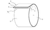
図1はこの発明の実施に用いることができる積層体を跨張して例示する斜視図であり、図中1は、たとえば、熱可塑性樹脂フィルムの単層もしくは積層構造とすることができる。ガスバリア性の薄膜状フィルムインナーライナを示し、2は、その薄膜状フィルムインナーライナ1の、後に述べる未加硫隣接ゴムシートへの貼着面に、その全面にわたって、もしくは部分的に付加した接着剤層を示す。
FIG. 1 is a perspective view illustrating a laminate that can be used in the practice of the present invention. In the figure, 1 can be, for example, a single layer or a laminated structure of a thermoplastic resin film. A gas barrier thin film inner liner is shown, and 2 is an adhesive that is applied over the entire surface or a part of the thin film
また3は、フィルムインナーライナ1に、接着剤層2を介して貼着される、インナーライナ用ゴムシート、スキージゴム用ゴムシート、カーカスプライ用コードを埋設したゴムシート等とすることができる未加硫隣接ゴムシートを示す。
ここで図示のこの積層体4は、フィルムインナーライナ1とゴムシート3との幅を揃える一方で、それら両者の長さ方向の各端位置を、それらの延在方向に相互にずらした状態で、フィルムインナーライナ1とゴムシート3とを、接着剤層2の介在下で貼着させてなる。
なお、フィルムインナーライナ1とゴムシート3との幅は揃わない場合もある。
This laminated body 4 shown here is in a state in which the widths of the film
In addition, the width | variety of the film
この発明の実施に当っては、以上のような積層体4の一本もしくは複数本において、ゴムシート3の、フィルムインナーライナ1からの突出部分を、積層体4の成型型への巻付け始端部分4aの一部とし、このような積層体4のたとえば一本を、図2に示すように成型型5の周面に巻付けるに当っては、成型型5の表面に対し、フィルムインナーライナ2が内側となる姿勢として、巻付け始端部分4aの前記突出部分で粘着させて、積層体4の巻付け始端を成型型表面に位置決めするとともに、その成型型5の回動変位下で、成型型5の周面上に、積層体4を成型型5の全周にわたって巻付け、そして、一周にわたるその巻付けの終了に当っては、成型型5の表面に予め粘着させた、積層体巻付け始端部分4aをそこから一端剥離させた状態で、積層体4の巻付け終端部分4bを、図3に模式的に示すように巻付け始端部4aの内周側に入れ込み、そこで、薄膜状フィルムインナーライナ1の端部分どうしを、接着剤層2の作用下で、たとえば、直接的に重ね合わせ接合させるとともに、未加硫隣接ゴムシート3の端部分どうしを、ゴムシート3に固有の粘着力の下で、たとえば、直接的に重ね合わせ接合させ、これらの両接合を、成型型5の周方向に間隔をおいて位置させる。
In carrying out the present invention, in one or a plurality of the laminates 4 as described above, the protruding portion of the
ガスバリア性の薄膜状フィルムインナーライナ1を、このようにして成型型5の周面に巻付け配置することにより、薄膜状フィルムインナーライナ1の取り扱いを容易にして、それの、成型型5への所要の巻付けを、高い作業能率の下で簡易に行うことができ、また、積層体4の巻付け始端部分の、ゴムシート3の突出部分を成型型5の表面に粘着させることにより、その積層体4の巻付け始端、ひいては、フィルムインナーライナ1の巻付け始端を、所期した通りの位置に正確に位置決めすることができる。
The gas barrier thin film film
またここでは、フィルムインナーライナ1の端部分どうしを、フィルムインナーライナ1への未加硫隣接ゴムシート3の貼着のための接着剤層2を介して接合させるとともに、未加硫隣接ゴムシート3の端部分どうしを、そのゴムシート3に固有の粘着力によって接合させることにより、積層体の端部分どうしの接合のための新たな接着剤の付設を不要にできる利点がある。
Further, here, the end portions of the film
ところで、以上に述べたところにおいて、薄膜状フィルムインナーライナ1の樹脂材料は、エチレン−ビニルアルコール共重合体を反応させて得られる変性エチレン−ビニルアルコール共重合体からなるマトリックス中に、23℃におけるヤング率が前記変性エチレン−ビニルアルコール共重合体より小さい柔軟樹脂を分散させた樹脂組成物からなる層を少なくとも含むものとすることが好ましく、また、前記樹脂組成物からなる層に隣接して、更にエラストマーからなる補助層を一層以上具えるものとすること、前記樹脂組成物からなる層の厚さを100μm以下とすること、および、前記樹脂組成物からなる層と補助層との間、及び前記補助層と補助層との間の少なくとも一箇所に、一層以上の接着剤層を具えるものとすることが好ましい。
By the way, in the place mentioned above, the resin material of the thin film
また、未加硫隣接ゴムシート3の貼着のための接着剤層2としては、ゴム成分100質量部に対し、分子中に反応部位を二つ以上有するマレイミド誘導体及びポリ―p―ジニトロソベンゼンの少なくとも一種を0.1質量部以上配合した接着剤組成物を用いることが好ましい。
The
なおここで、複数本の積層体4、たとえば二本の積層体4を、成型型5の周面に、それの一周にわたって巻付ける場合は、それぞれの積層体4を、図1に示すように形成したところにおいて、一方の積層体4の巻付け始端部分4aの一部としての、ゴムシート3の突出部分を、成型型5の表面に直接的に粘着させて、その積層体4を、成型型5の周面に巻付ける一方で、他方の積層体4の巻付け始端部分4aの一部としてのゴムシート3の突出部分を、一方の積層体4の巻付け終端部分4bを介して成型型5の表面に間接的に粘着させ、これによって、一方の積層体4の巻付け終端部分4bの、薄膜状フィルムインナーライナ1および未加硫隣接ゴムシート3のそれぞれの端部分に対し、他方の積層体4の巻付け始端部分4aの、薄膜状フィルムインナーライナ1および未加硫隣接ゴムシート3のそれぞれの端部分を、成型型5の周方向に間隔をおいた位置で、たとえば、直接的に重ね合わせ接合させることが、一本の積層体4を成型型5の全周にわたって、巻付ける場合との、構造上の差異を小さくする上で好ましい。
Here, when a plurality of laminated bodies 4, for example, two laminated bodies 4 are wound around the circumferential surface of the
そして、これらのいずれの巻付け態様を採用する場合にあっても、未加硫隣接ゴムシート3どうしの接合域aの、成型型5の周方向長さは0〜20mmの範囲とし、また、薄膜状フィルムインナーライナ1の端部分どうしの接合域bの同様の長さは0<b≦60mmの範囲とすることが好ましい。
And even in the case of adopting any of these winding modes, the circumferential length of the
そしてまた、上述したようなそれぞれの接合域の相互の、成型型5の周方向の離隔距離cは、0〜60mmの範囲とすることが、積層体の後端部分を、貼り付け直す際の作業性を高めることができる。
すなわち、60mmを越えると貼損じたり精度が低下するおそれが高まることになる。
In addition, the mutual separation distance c in the circumferential direction of the molding die 5 between each of the bonding regions as described above is in the range of 0 to 60 mm, when the rear end portion of the laminate is re-applied. Workability can be improved.
That is, when it exceeds 60 mm, there is a high possibility that the paste may be damaged or the accuracy may be reduced.
1 薄膜状フィルムインナーライナ
2 接着剤層
3 未加硫隣接ゴムシート
4 積層体
4a 巻付け始端部分
4b 巻付け終端部分
5 成型型
a,b 接合部
c 離隔距離
DESCRIPTION OF
Claims (5)
Priority Applications (2)
| Application Number | Priority Date | Filing Date | Title |
|---|---|---|---|
| JP2008170148A JP5140503B2 (en) | 2008-06-30 | 2008-06-30 | Raw tire molding method |
| PCT/JP2009/061979 WO2010001901A1 (en) | 2008-06-30 | 2009-06-30 | Method of forming green tire |
Applications Claiming Priority (1)
| Application Number | Priority Date | Filing Date | Title |
|---|---|---|---|
| JP2008170148A JP5140503B2 (en) | 2008-06-30 | 2008-06-30 | Raw tire molding method |
Publications (2)
| Publication Number | Publication Date |
|---|---|
| JP2010005986A true JP2010005986A (en) | 2010-01-14 |
| JP5140503B2 JP5140503B2 (en) | 2013-02-06 |
Family
ID=41465993
Family Applications (1)
| Application Number | Title | Priority Date | Filing Date |
|---|---|---|---|
| JP2008170148A Expired - Fee Related JP5140503B2 (en) | 2008-06-30 | 2008-06-30 | Raw tire molding method |
Country Status (2)
| Country | Link |
|---|---|
| JP (1) | JP5140503B2 (en) |
| WO (1) | WO2010001901A1 (en) |
Cited By (14)
| Publication number | Priority date | Publication date | Assignee | Title |
|---|---|---|---|---|
| JP2010167829A (en) * | 2009-01-20 | 2010-08-05 | Yokohama Rubber Co Ltd:The | Pneumatic tire and method for manufacturing the same |
| WO2012066816A1 (en) * | 2010-11-17 | 2012-05-24 | 住友ゴム工業株式会社 | Production method for pneumatic tire |
| WO2012086276A1 (en) * | 2010-12-22 | 2012-06-28 | 横浜ゴム株式会社 | Pneumatic tire |
| WO2012165512A1 (en) | 2011-05-31 | 2012-12-06 | 株式会社ブリヂストン | Laminate, tire, and method for producing tire |
| JP2012240658A (en) * | 2011-05-24 | 2012-12-10 | Yokohama Rubber Co Ltd:The | Pneumatic tire |
| WO2013051325A1 (en) * | 2011-10-04 | 2013-04-11 | 住友ゴム工業株式会社 | Method for manufacturing pneumatic tires |
| WO2013054602A1 (en) * | 2011-10-11 | 2013-04-18 | 住友ゴム工業株式会社 | Method for producing pneumatic tire |
| JP2013078883A (en) * | 2011-10-04 | 2013-05-02 | Sumitomo Rubber Ind Ltd | Method for manufacturing pneumatic tire |
| JP2013086460A (en) * | 2011-10-21 | 2013-05-13 | Sumitomo Rubber Ind Ltd | Manufacturing method for pneumatic tire |
| JP2013091249A (en) * | 2011-10-26 | 2013-05-16 | Sumitomo Rubber Ind Ltd | Method for manufacturing pneumatic tire |
| JP2013099898A (en) * | 2011-11-09 | 2013-05-23 | Sumitomo Rubber Ind Ltd | Method for manufacturing pneumatic tire |
| JP2013107332A (en) * | 2011-11-22 | 2013-06-06 | Sumitomo Rubber Ind Ltd | Method for producing pneumatic tire |
| JP2013136224A (en) * | 2011-11-29 | 2013-07-11 | Sumitomo Rubber Ind Ltd | Method for manufacturing pneumatic tires |
| JP2016052789A (en) * | 2015-11-02 | 2016-04-14 | 横浜ゴム株式会社 | Manufacturing method of pneumatic tire |
Families Citing this family (1)
| Publication number | Priority date | Publication date | Assignee | Title |
|---|---|---|---|---|
| ITTO20120778A1 (en) * | 2012-09-10 | 2014-03-11 | Bridgestone Europ Nv | METHOD AND CONSTRUCTION STATION OF A TIRE |
Family Cites Families (4)
| Publication number | Priority date | Publication date | Assignee | Title |
|---|---|---|---|---|
| JP2000272023A (en) * | 1999-03-26 | 2000-10-03 | Yokohama Rubber Co Ltd:The | Production of pneumatic tire |
| JP4122031B2 (en) * | 2006-03-29 | 2008-07-23 | 横浜ゴム株式会社 | Pneumatic tire manufacturing method |
| JP5016248B2 (en) * | 2006-04-06 | 2012-09-05 | 株式会社ブリヂストン | tire |
| JP2008221638A (en) * | 2007-03-13 | 2008-09-25 | Bridgestone Corp | Manufacturing method and manufacturing apparatus for sheet-form tire constituting member |
-
2008
- 2008-06-30 JP JP2008170148A patent/JP5140503B2/en not_active Expired - Fee Related
-
2009
- 2009-06-30 WO PCT/JP2009/061979 patent/WO2010001901A1/en active Application Filing
Cited By (30)
| Publication number | Priority date | Publication date | Assignee | Title |
|---|---|---|---|---|
| JP2010167829A (en) * | 2009-01-20 | 2010-08-05 | Yokohama Rubber Co Ltd:The | Pneumatic tire and method for manufacturing the same |
| EP2623304A4 (en) * | 2010-11-17 | 2016-11-23 | Sumitomo Rubber Ind | Production method for pneumatic tire |
| WO2012066816A1 (en) * | 2010-11-17 | 2012-05-24 | 住友ゴム工業株式会社 | Production method for pneumatic tire |
| JP2012106403A (en) * | 2010-11-17 | 2012-06-07 | Sumitomo Rubber Ind Ltd | Pneumatic tire manufacturing method |
| US10046532B2 (en) | 2010-11-17 | 2018-08-14 | Sumitomo Rubber Industries, Ltd. | Method for manufacturing pneumatic tire |
| WO2012086276A1 (en) * | 2010-12-22 | 2012-06-28 | 横浜ゴム株式会社 | Pneumatic tire |
| JP2012144238A (en) * | 2010-12-22 | 2012-08-02 | Yokohama Rubber Co Ltd:The | Pneumatic tire |
| US10293644B2 (en) | 2010-12-22 | 2019-05-21 | The Yokohama Rubber Co., Ltd. | Pneumatic tire |
| JP2012240658A (en) * | 2011-05-24 | 2012-12-10 | Yokohama Rubber Co Ltd:The | Pneumatic tire |
| WO2012165512A1 (en) | 2011-05-31 | 2012-12-06 | 株式会社ブリヂストン | Laminate, tire, and method for producing tire |
| US9815330B2 (en) | 2011-05-31 | 2017-11-14 | Bridgestone Corporation | Laminate, tire, and method for producing tire |
| WO2013051325A1 (en) * | 2011-10-04 | 2013-04-11 | 住友ゴム工業株式会社 | Method for manufacturing pneumatic tires |
| EP3330065A1 (en) * | 2011-10-04 | 2018-06-06 | Sumitomo Rubber Industries, Ltd. | Method for manufacturing pneumatic tires |
| US10464300B2 (en) | 2011-10-04 | 2019-11-05 | Sumitomo Rubber Industries, Ltd. | Method for manufacturing pneumatic tire |
| JP2013078883A (en) * | 2011-10-04 | 2013-05-02 | Sumitomo Rubber Ind Ltd | Method for manufacturing pneumatic tire |
| EP3351372A1 (en) * | 2011-10-04 | 2018-07-25 | Sumitomo Rubber Industries, Ltd. | Method for manufacturing pneumatic tires |
| CN103842165A (en) * | 2011-10-04 | 2014-06-04 | 住友橡胶工业株式会社 | Method for manufacturing pneumatic tires |
| US20140261976A1 (en) * | 2011-10-04 | 2014-09-18 | Sumitomo Rubber Industries, Ltd. | Method for manufacturing pneumatic tire |
| EP2749403A4 (en) * | 2011-10-04 | 2016-01-06 | Sumitomo Rubber Ind | Method for manufacturing pneumatic tires |
| EP3330066A1 (en) * | 2011-10-04 | 2018-06-06 | Sumitomo Rubber Industries, Ltd. | Method for manufacturing pneumatic tires |
| EP3330067A1 (en) * | 2011-10-04 | 2018-06-06 | Sumitomo Rubber Industries, Ltd. | Method for manufacturing pneumatic tires |
| EP3326793A1 (en) * | 2011-10-04 | 2018-05-30 | Sumitomo Rubber Industries, Ltd. | Method for manufacturing pneumatic tires |
| JP2013082139A (en) * | 2011-10-11 | 2013-05-09 | Sumitomo Rubber Ind Ltd | Method for manufacturing pneumatic tire |
| WO2013054602A1 (en) * | 2011-10-11 | 2013-04-18 | 住友ゴム工業株式会社 | Method for producing pneumatic tire |
| JP2013086460A (en) * | 2011-10-21 | 2013-05-13 | Sumitomo Rubber Ind Ltd | Manufacturing method for pneumatic tire |
| JP2013091249A (en) * | 2011-10-26 | 2013-05-16 | Sumitomo Rubber Ind Ltd | Method for manufacturing pneumatic tire |
| JP2013099898A (en) * | 2011-11-09 | 2013-05-23 | Sumitomo Rubber Ind Ltd | Method for manufacturing pneumatic tire |
| JP2013107332A (en) * | 2011-11-22 | 2013-06-06 | Sumitomo Rubber Ind Ltd | Method for producing pneumatic tire |
| JP2013136224A (en) * | 2011-11-29 | 2013-07-11 | Sumitomo Rubber Ind Ltd | Method for manufacturing pneumatic tires |
| JP2016052789A (en) * | 2015-11-02 | 2016-04-14 | 横浜ゴム株式会社 | Manufacturing method of pneumatic tire |
Also Published As
| Publication number | Publication date |
|---|---|
| JP5140503B2 (en) | 2013-02-06 |
| WO2010001901A1 (en) | 2010-01-07 |
Similar Documents
| Publication | Publication Date | Title |
|---|---|---|
| JP5140503B2 (en) | Raw tire molding method | |
| JP4989449B2 (en) | Pneumatic tire manufacturing method and pneumatic tire | |
| CN102785533B (en) | Air-inflation tyre and manufacture method thereof | |
| US8900389B2 (en) | Method for producing pneumatic tire | |
| JP2011235635A5 (en) | ||
| US8696846B2 (en) | Method of manufacturing a pneumatic tire | |
| JP2006198848A (en) | Pneumatic tire and its manufacturing method | |
| US20190143764A1 (en) | Pneumatic tire with noise damper | |
| WO2006106722A1 (en) | Method of repairing inside surface portion of pneumatic tire, and relevant inside surface portion repair material | |
| JP2012006499A (en) | Pneumatic tire and method of manufacturing the same | |
| US8926774B2 (en) | Method for manufacturing a pneumatic tire | |
| JP2009208444A (en) | Method for molding of inner liner | |
| JP4948750B2 (en) | Method of forming the sole of footwear from slab material | |
| US11292298B2 (en) | Noise damper bonded to tire using adhesives | |
| JP2006272809A (en) | Repairing method of inner surface part of pneumatic tire | |
| KR101251424B1 (en) | Manufacturing Method For Pneumatic Tire And The Pneumatic Tire Thereof | |
| JP2009083733A (en) | Pneumatic tire | |
| JP3665038B2 (en) | Rubber bag and manufacturing method thereof | |
| JP2011224907A (en) | Method of manufacturing pneumatic tire | |
| JP2007160833A (en) | Manufacturing method of annular hollow body | |
| JP5646983B2 (en) | Inner liner, its manufacturing method and pneumatic tire | |
| JP2010046986A (en) | Tire manufacturing method | |
| JP2010069733A (en) | Green-tire molding apparatus and method of tire manufacture | |
| JP6282370B1 (en) | Manufacturing method of large flexible membrane rolling weir body | |
| JP2009214826A (en) | Tire constituting member |
Legal Events
| Date | Code | Title | Description |
|---|---|---|---|
| A621 | Written request for application examination |
Free format text: JAPANESE INTERMEDIATE CODE: A621 Effective date: 20110421 |
|
| A131 | Notification of reasons for refusal |
Free format text: JAPANESE INTERMEDIATE CODE: A131 Effective date: 20120807 |
|
| A521 | Request for written amendment filed |
Free format text: JAPANESE INTERMEDIATE CODE: A523 Effective date: 20120925 |
|
| TRDD | Decision of grant or rejection written | ||
| A01 | Written decision to grant a patent or to grant a registration (utility model) |
Free format text: JAPANESE INTERMEDIATE CODE: A01 Effective date: 20121023 |
|
| A01 | Written decision to grant a patent or to grant a registration (utility model) |
Free format text: JAPANESE INTERMEDIATE CODE: A01 |
|
| A61 | First payment of annual fees (during grant procedure) |
Free format text: JAPANESE INTERMEDIATE CODE: A61 Effective date: 20121119 |
|
| R150 | Certificate of patent or registration of utility model |
Ref document number: 5140503 Country of ref document: JP Free format text: JAPANESE INTERMEDIATE CODE: R150 Free format text: JAPANESE INTERMEDIATE CODE: R150 |
|
| FPAY | Renewal fee payment (event date is renewal date of database) |
Free format text: PAYMENT UNTIL: 20151122 Year of fee payment: 3 |
|
| R250 | Receipt of annual fees |
Free format text: JAPANESE INTERMEDIATE CODE: R250 |
|
| R250 | Receipt of annual fees |
Free format text: JAPANESE INTERMEDIATE CODE: R250 |
|
| R250 | Receipt of annual fees |
Free format text: JAPANESE INTERMEDIATE CODE: R250 |
|
| R250 | Receipt of annual fees |
Free format text: JAPANESE INTERMEDIATE CODE: R250 |
|
| R250 | Receipt of annual fees |
Free format text: JAPANESE INTERMEDIATE CODE: R250 |
|
| R250 | Receipt of annual fees |
Free format text: JAPANESE INTERMEDIATE CODE: R250 |
|
| LAPS | Cancellation because of no payment of annual fees |