JP2010005796A - Authenticity identification element - Google Patents
Authenticity identification element Download PDFInfo
- Publication number
- JP2010005796A JP2010005796A JP2008164343A JP2008164343A JP2010005796A JP 2010005796 A JP2010005796 A JP 2010005796A JP 2008164343 A JP2008164343 A JP 2008164343A JP 2008164343 A JP2008164343 A JP 2008164343A JP 2010005796 A JP2010005796 A JP 2010005796A
- Authority
- JP
- Japan
- Prior art keywords
- layer
- liquid crystal
- thin film
- hologram
- black
- Prior art date
- Legal status (The legal status is an assumption and is not a legal conclusion. Google has not performed a legal analysis and makes no representation as to the accuracy of the status listed.)
- Granted
Links
Images
Abstract
Description
本発明は、不正な意図に基づく偽造や改ざん等により得られたものと真正なものとの区別を可能にした真正性識別体に関するものである。また、本発明は、そのような真正性識別体を物品に適用するのに適するラベルの形態や転写シートの形態に加工したものにも関するものである。 The present invention relates to an authenticity identifier that makes it possible to distinguish between an object obtained by forgery or falsification based on an unauthorized intention and an authentic object. The present invention also relates to a product in which such an authenticity identifier is processed into a label form or transfer sheet form suitable for application to an article.
本明細書において、配合を示す「部」は質量基準である。また、「ホログラム」はホログラムと、回折格子などの光回折性機能を有するものも含む。 In the present specification, “part” indicating the formulation is based on mass. The “hologram” includes a hologram and a hologram having a light diffractive function such as a diffraction grating.
(主なる用途)本発明のホログラムシートの主なる用途としては、偽造防止分野に使用されるホログラムシートであって、具体的には、クレジットカード等の偽造されて使用されると、カード保持者やカード会社等に損害を与え得るもの、運転免許証、社員証、会員証等の身分証明書、入学試験用の受験票、パスポート等、紙幣、商品券、ポイントカード、株券、証券、抽選券、馬券、預金通帳、乗車券、通行券、航空券、種々の催事の入場券、遊戯券、交通機関や公衆電話用のプリペイドカード等がある。 (Main use) The main use of the hologram sheet of the present invention is a hologram sheet used in the field of anti-counterfeiting. Specifically, when used as a counterfeit such as a credit card, the card holder That may cause damage to the credit card company, driver's license, employee ID card, membership card, ID card, entrance examination voucher, passport, banknote, gift certificate, point card, stock certificate, securities, lottery ticket There are horse tickets, bankbooks, boarding tickets, pass tickets, air tickets, admission tickets for various events, play tickets, prepaid cards for public transportation and public telephones.
これらはいずれも、経済的、もしくは社会的な価値を有する情報を保持した情報記録体であり、偽造による損害を防止する目的で、記録体そのものの真正性を識別できる機能を有することが望まれる。 Each of these is an information recording body that holds information having economic or social value, and it is desirable to have a function that can identify the authenticity of the recording body for the purpose of preventing damage caused by forgery. .
また、これら情報記録体以外であっても、高額商品、例えば、高級腕時計、高級皮革製品、貴金属製品、もしくは宝飾品等の、しばしば、高級ブランド品と言われるもの、または、それら高額商品の収納箱やケース等も偽造され得るものである。また、量産品でも有名ブランドのもの、例えば、オーディオ製品、電化製品等、または、それらに吊り下げられるタグも、偽造の対象となりやすい。 In addition to these information recording media, expensive products such as luxury watches, luxury leather products, precious metal products, jewelry, etc., often referred to as luxury brand products, or storage of such expensive products. Boxes and cases can also be forged. In addition, mass-produced products of famous brands, such as audio products, electrical appliances, etc., or tags that are hung on them are also subject to forgery.
さらに、著作物である音楽ソフト、映像ソフト、コンピュータソフト、もしくはゲームソフト等が記録された記憶体、またはそれらのケース等も、やはり偽造の対象となり得る。また、プリンター用のトナー、用紙など、交換する備品を純正材料に限定している製品などにも、偽造による損害を防止する目的で、そのものの真正性を識別できる機能を有することが望まれる。 Furthermore, a storage body in which music software, video software, computer software, game software, or the like, which is a copyrighted work, or cases thereof can also be forged. In addition, it is desirable that products such as printer toner, paper, and the like in which supplies to be replaced are limited to genuine materials have a function of identifying their authenticity for the purpose of preventing damage caused by forgery.
(背景技術)
従来、情報記録体や上記した種々の物品(総称して、真正性識別対象物と言う。)の偽造を防止する目的で、その構造の精密さから、製造上の困難性を有すると言われるホログラムを真正性の識別可能なものとして適用することが多く行なわれている。しかしながら、ホログラムの製造方法自体は知られており、その方法により精密な加工を施すことができることから、ホログラムが単に目視による判定だけのものであるときは、真正なホログラムと偽造されたホログラムとの区別は困難である。
(Background technology)
Conventionally, for the purpose of preventing forgery of information recording bodies and the above-mentioned various articles (collectively referred to as authenticity identification objects), it is said that they have manufacturing difficulties due to the precision of their structures. Often, holograms are applied as authenticity distinguishable. However, since the hologram manufacturing method itself is known and can be precisely processed by that method, when the hologram is merely for visual judgment, there is no difference between a genuine hologram and a forged hologram. It is difficult to distinguish.
これらの真正性識別対象物、特にラベル形態や転写形態にてホログラム画像を施された物品は、ホログラム画像の目視確認という真正性識別のみでなく、新たな真正性識別方法を用いてその対象物の真正性を識別する必要が生じている。 These authentic identification objects, in particular, articles that have been subjected to hologram images in a label form or transfer form, are not only used for authentic identification of visual confirmation of hologram images, but also by using a new authenticity identification method. There is a need to identify the authenticity of.
(先行技術)
これらの要求に応えるため、ホログラムに積層して、入射した光の内、左回り偏光もしくは、右回り偏光のいずれか一方の光のみを反射する光選択反射層を有する真正性識別体が提案された。(例えば、特許文献1参照。)
この光選択反射層として、コレステリック液晶を使用し、偏光版等を用いて確認する方法で偽造防止性を高めている。
(Prior art)
In order to meet these requirements, an authenticity discriminator having a light selective reflection layer that is laminated on a hologram and reflects only one of the left-handed polarized light and the right-handed polarized light in the incident light is proposed. It was. (For example, refer to Patent Document 1.)
As this light selective reflection layer, cholesteric liquid crystal is used, and the anti-counterfeiting property is enhanced by a method of confirming using a polarizing plate or the like.
しかしながら、特許文献1の記載にあるように、ホログラム形成層上の反射性薄膜層の反射率が高いため、コレステリック液晶層で反射されず透過した光(選択的反射光の補色光)が、この反射性薄膜層で反射し、再びコレステリック液晶層へ戻る(以下戻り光とする)ことにより、この戻り光が、コレステリック液晶を観察する際のノイズ成分となって、選択的反射光に付加・混在し、液晶本来の色調とならず、視認・識別することすら難しくなっていた。 However, as described in Patent Document 1, since the reflectance of the reflective thin film layer on the hologram forming layer is high, the light that is transmitted without being reflected by the cholesteric liquid crystal layer (complementary light of selective reflected light) Reflecting on the reflective thin film layer and returning to the cholesteric liquid crystal layer again (hereinafter referred to as return light), this return light becomes a noise component when observing the cholesteric liquid crystal and is added to and mixed with the selectively reflected light. However, the color tone was not the original color of the liquid crystal, and it was even difficult to see and identify.
このため、特許文献1において、反射性薄膜層を部分的に形成又は除去し、形成していない部分又は除去した部分において上記液晶層を視認するという工夫がなされている。この形成又は部分的除去方法には、遮蔽部と開口部を有するパターンマスクを介して薄膜形成を行い、遮蔽部のある部分では基材への薄膜形成をさせない方法、もしくは、水溶性樹脂パターンを利用して、その水溶性樹脂パターン上を含む基材全面に反射性薄膜層を形成し、水溶性樹脂パターンの有る部分のみ水溶液等により除去して、反射性薄膜層のパターン化を行う方法等が示されている。 For this reason, in Patent Document 1, a contrivance is made such that the reflective thin film layer is partially formed or removed, and the liquid crystal layer is visually recognized in a portion that is not formed or removed. In this formation or partial removal method, a thin film is formed through a pattern mask having a shielding portion and an opening, and a thin film is not formed on a substrate in a portion having the shielding portion, or a water-soluble resin pattern is used. Utilizing this method, a reflective thin film layer is formed on the entire surface of the substrate including the water-soluble resin pattern, and only the portion with the water-soluble resin pattern is removed with an aqueous solution, etc., and the reflective thin film layer is patterned. It is shown.
前者は、基材上にパターンマスクを設置し、パターンマスク上から基材へ薄膜形成を実施、パターンマスクの開口部にのみ薄膜が形成され、その後パターンマスクを取り外すことにより、部分的な薄膜形成を実現するものであるが、パターンマスク作成作業や、その設置・取り外し作業が煩雑であるだけでなく、パターンの位置精度が不十分という欠点を有する。 The former places a pattern mask on the substrate, forms a thin film from the pattern mask to the substrate, forms a thin film only at the opening of the pattern mask, and then removes the pattern mask to form a partial thin film. However, there are disadvantages in that not only the pattern mask creation work and its installation / removal work are complicated, but also the pattern position accuracy is insufficient.
後者では、除去する部分に水溶性樹脂もしくは水膨潤性樹脂を溶解または分散した水溶性インキでパターン印刷を施し、全面に反射性薄膜層を形成、その後、その面に水、又は酸性もしくはアルカリ性の水溶液等を接触させて、水溶性樹脂パターンを除去すると共に、水溶性樹脂パターンが積層されていた部分の反射性薄膜層を除去することにより、水溶性樹脂パターンが積層されていなかった部分の反射性薄膜層を残し、反射性薄膜層をパターン状に形成するものであり、その作業は非常に煩雑である。 In the latter, pattern printing is performed with a water-soluble ink in which a water-soluble resin or a water-swellable resin is dissolved or dispersed in a portion to be removed, and a reflective thin film layer is formed on the entire surface, and then water, acid or alkaline is formed on the surface. The water-soluble resin pattern is removed by contacting with an aqueous solution, and the reflective thin film layer where the water-soluble resin pattern is laminated is removed, thereby reflecting the portion where the water-soluble resin pattern is not laminated. The reflective thin film layer is formed in a pattern while leaving the conductive thin film layer, and the operation is very complicated.
さらに、その反射性薄膜層を除去した部分に、黒色染料を含む粘着層を設ける等により、前記補色光を吸収する方法が提案されているが、透明樹脂層とその粘着剤層の界面でその補色光が界面反射を生じ、黒色染料による光吸収による反射光削減効果が十分発揮できないとういう欠点を有する。また、黒色染料の光吸収性は、可視光全域をカバーしていない。従って、反射性薄膜層を除去しても未だ補色光の反射が生じ、結局、コレステリック液晶層の視認性の低下を招くことになっていた。 Furthermore, a method of absorbing the complementary color light by, for example, providing an adhesive layer containing a black dye in a portion from which the reflective thin film layer has been removed has been proposed, but at the interface between the transparent resin layer and the adhesive layer. The complementary color light causes interface reflection, and has a disadvantage that the reflected light reduction effect due to light absorption by the black dye cannot be sufficiently exhibited. Moreover, the light absorptivity of the black dye does not cover the entire visible light region. Accordingly, even if the reflective thin film layer is removed, the complementary color light is still reflected, and the visibility of the cholesteric liquid crystal layer is lowered.
そこで、本発明はこのような問題点を解消するためになされたものである。その目的は、コレステリック液晶層とホログラム形成層を積層したことによるコレステリック液晶層の判別性の劣化が少なく、真正性の識別が容易である真正性識別体を提供することである。 Accordingly, the present invention has been made to solve such problems. The purpose is to provide an authenticity discriminator that is easy to discriminate authenticity with little deterioration of the discriminability of the cholesteric liquid crystal layer due to the lamination of the cholesteric liquid crystal layer and the hologram forming layer.
上記の課題を解決するために、
本発明の真正性識別体の第1の態様は、 透明基材の一方の面の少なくとも一部にコレステリック液晶層が設けられ、前記透明基材の他方の面に、ホログラムレリーフを有する透明樹脂層、及び、前記ホログラムレリーフ上の一部であって、少なくとも前記コレステリック液晶層に相対する位置に、前記透明樹脂層との屈折率差が0.05以内である黒色パターン層を設け、前記黒色パターン層及び前記ホログラムレリーフに接するよううに反射性薄膜層を設けたことを特徴とするものである。
To solve the above problem,
In a first aspect of the authenticity identifier of the present invention, a transparent resin layer having a cholesteric liquid crystal layer provided on at least a part of one surface of a transparent substrate and having a hologram relief on the other surface of the transparent substrate. A black pattern layer having a refractive index difference of 0.05 or less with respect to the transparent resin layer is provided at least at a position corresponding to the cholesteric liquid crystal layer on a part of the hologram relief; A reflective thin film layer is provided so as to contact the layer and the hologram relief.
上記第1の態様の真正性識別体によれば、
ホログラムレリーフを有する透明樹脂層と、反射性薄膜層との間であって、少なくともそのコレステリック液晶層に相対する位置に、黒色パターン層が設けられていることで、観察のためにコレステリック液晶へ入射した光(観察光)の内、所定の光がまずこの液晶層で反射され(選択的反射光)、それ以外の光(反射光の補色となる光、補色光とする。)がこの液晶層を通過し、反射性薄膜層へ届いて、この層で全反射されるところ、この黒色パターン層が設けられている部分のみ、この黒色パターン層においてこの補色光が全波長域に渡って吸収され、反射性薄膜層へ届くことがなく、不要な反射光(以下、ノイズともいう。)を発生させないため、観察側からみると、コレステリック液晶層から反射される、本来の選択的反射光のみが観察され、その存在を容易に、精度よく識別することができる。
According to the authenticity identifier of the first aspect,
A black pattern layer is provided between the transparent resin layer having the hologram relief and the reflective thin film layer, at least at a position opposite to the cholesteric liquid crystal layer, so that it enters the cholesteric liquid crystal for observation. Of the light (observation light), predetermined light is first reflected by this liquid crystal layer (selective reflected light), and other light (light that is complementary to the reflected light and complementary color light) is this liquid crystal layer. Passes through the reflective thin film layer and is totally reflected by this layer, but only the portion where the black pattern layer is provided absorbs the complementary color light over the entire wavelength range. Since it does not reach the reflective thin film layer and does not generate unnecessary reflected light (hereinafter also referred to as noise), only the original selectively reflected light reflected from the cholesteric liquid crystal layer is seen from the observation side. Is observation, its presence can be easily identified accurately.
このような黒色パターン層は、微粒子カーボンブラック等の、観察する光(可視光)の全波長領域に対する吸収性を有する顔料を使用している。これに対して黒色染料は、染料構造に依存する光吸収特性により部分的に吸収性が落ちる上、光吸収特性そのものが弱く、上記補色光を完全に吸収するためには、その黒色層の厚さをかなり厚くする必要があった。 Such a black pattern layer uses a pigment having absorptivity for the entire wavelength region of light to be observed (visible light) such as fine-particle carbon black. On the other hand, the black dye partially loses its absorbency due to the light absorption characteristic depending on the dye structure, and the light absorption characteristic itself is weak. In order to completely absorb the complementary color light, the thickness of the black layer is not sufficient. It was necessary to increase the thickness considerably.
その上、透明樹脂層と、粘着剤層を構成する樹脂とは、通常、使われる樹脂系が異なるため、その界面での界面反射が発生する。この界面反射は、接する層の屈折率に差があると発生(0.01の差でも発生)し、その屈折率差が大きいほど強く反射する(0.05以上の差ではかなり強く反射する)とともに、入射する波長によってその強さが変化するため、この界面反射がまたコレステリック液晶を観察する際のノイズ成分となる。 In addition, since the transparent resin layer and the resin constituting the pressure-sensitive adhesive layer are usually used in different resin systems, interfacial reflection occurs at the interface. This interfacial reflection occurs when there is a difference in the refractive index of the layers in contact (occurs even with a difference of 0.01), and the greater the difference in the refractive index, the stronger the reflection (a difference of 0.05 or more reflects fairly strongly). At the same time, since the intensity varies depending on the incident wavelength, this interface reflection also becomes a noise component when observing the cholesteric liquid crystal.
このため、黒色パターン層には、光吸収性に波長依存性の無い、微粒子カーボンブランク等の黒色顔料を使用し、且つ、ホログラムレリーフを有する透明樹脂層の屈折率と同様の屈折率を有する樹脂(屈折率差が0.05以内)を使用する。このことにより、この2層の界面での界面反射を抑え、コレステリック液晶を観察する際のノイズ成分を解消することができ、結果として、視認性を改善することができる。 Therefore, for the black pattern layer, a resin having a refractive index similar to that of the transparent resin layer having a hologram relief, using a black pigment such as a fine particle carbon blank having no wavelength dependency in light absorption. (Refractive index difference is within 0.05). As a result, interface reflection at the interface between the two layers can be suppressed, noise components when observing the cholesteric liquid crystal can be eliminated, and as a result, visibility can be improved.
その透明樹脂層としては、アクリル系等の熱可塑性樹脂や、エポキシ変性不飽和ポリエステル樹脂系等の熱硬化性樹脂が使用されるため、黒色パターン層に使用する樹脂は、これらの樹脂と同一系として、屈折率差を0.05以内に抑えるとともに、層間の接着性を確保することができる。また、他の樹脂系であっても、その2つの点を留意して選択することにより、同様の効果を得ることができる。 As the transparent resin layer, a thermoplastic resin such as acrylic or a thermosetting resin such as epoxy-modified unsaturated polyester resin is used. Therefore, the resin used for the black pattern layer is the same as those resins. As described above, the refractive index difference can be suppressed to within 0.05, and the adhesion between the layers can be ensured. Even in other resin systems, the same effect can be obtained by selecting the two points with attention.
カーボンブラックには、ランプブラック、ボーンブラック等より、チャンネルブラック、ファーネスブラック等の微粒子カーボンブラックのように著しい漆黒度と着色性を有するものを使用する。特に、ファーネスブラックはその表面が不活性であり安定しているため好適である。粒径は通常0.01〜0.1μm程度のものを使用し、上記樹脂に10〜50%程度添加し、十分に分散させて使用される。 As the carbon black, those having remarkably blackness and colorability such as fine carbon black such as channel black and furnace black are used rather than lamp black and bone black. Furnace black is particularly preferred because its surface is inert and stable. A particle size of about 0.01 to 0.1 μm is usually used, and about 10 to 50% is added to the resin and sufficiently dispersed.
黒色パターン層の形成方法は、上記した薄膜の部分的除去のような煩雑な作業を用いる必要は無く、オフセット印刷方式、グラビア印刷方式等、形成パターンに適宜な方式を用いることができる。但し、コレステリック液晶層の形成パターンに位置を合わせる(同調させるともいう。)という意味で、コレステリック液晶層と同一の形成方法を用いることが望ましい。さらには、形成厚さを比較的厚くすると共に、にじみや、インキダレを抑えるため、フレキソ印刷方式を用いることもできる。形成する厚さは、使用するカーボンブラックの特性、添加量により調整するが、通常2〜20μm程度とする。 The method for forming the black pattern layer does not require a complicated operation such as partial removal of the thin film described above, and an appropriate method can be used for the formation pattern, such as an offset printing method or a gravure printing method. However, it is desirable to use the same formation method as that of the cholesteric liquid crystal layer in the sense that the position is matched (also referred to as tuning) with the formation pattern of the cholesteric liquid crystal layer. Furthermore, a flexographic printing method can be used in order to make the formation thickness relatively thick and suppress bleeding and ink sag. The thickness to be formed is adjusted by the characteristics of carbon black to be used and the amount added, but is usually about 2 to 20 μm.
また、本発明の真正性識別体の第2の態様は、前記黒色パターン層の表面が粗面であって、前記反射性薄膜層のこの面に接する部分が前記粗面に追従していることを特徴とするものである。
上記第2の態様の真正性識別体によれば、反射性薄膜層の黒色パターン層と接する面が粗面となり、前記補色光の内、黒色パターン層で吸収されず透過してきた光を、反射性薄膜層面で全反射させず、散乱させることができる。このことにより、ノイズをさらに低減して、結果として、視認性を改善することができる。粗面とは、その断面形状が無秩序な凹凸となっており、よってその面で反射した光が散乱光となるものをいう。
Further, according to a second aspect of the authenticity identifier of the present invention, the surface of the black pattern layer is a rough surface, and a portion of the reflective thin film layer that is in contact with the surface follows the rough surface. It is characterized by.
According to the authenticity identifier of the second aspect, the surface of the reflective thin film layer in contact with the black pattern layer is a rough surface, and the light that has been transmitted without being absorbed by the black pattern layer is reflected among the complementary color light. Can be scattered without being totally reflected on the surface of the conductive thin film. This can further reduce noise and, as a result, improve visibility. The rough surface means that the cross-sectional shape is irregular irregularities, and thus the light reflected by the surface becomes scattered light.
黒色パターン層を粗面化する方法としては、黒色パターン形成方法を用いて粗面化する方法と、使用する顔料サイズを大きくすることで、その顔料が黒色パターン層表面を押し上げたり、飛び出したりして粗面化する方法がある。形成方法を用いる方法としては、パターン形成後、粗面パターンを有する型押しを施したり、シルクスクリーン印刷において使用するメッシュを粗くする方法等がある。顔料サイズを大きくする方法としては、カーボンブラックその他体質顔料等のサイズを黒色パターン層の厚さ程度の大きさとすると黒色パターン形成後その顔料が形成面より突出し、粗面となる。 As a method of roughening the black pattern layer, a method of roughening using the black pattern forming method and a method of increasing the pigment size to be used may cause the pigment to push up or jump out of the surface of the black pattern layer. There is a method to roughen the surface. As a method using the forming method, there is a method of performing embossing having a rough surface pattern after pattern formation or roughening a mesh used in silk screen printing. As a method for increasing the pigment size, if the size of carbon black and other extender pigments is about the thickness of the black pattern layer, after the black pattern is formed, the pigment protrudes from the formation surface to become a rough surface.
本発明の真正性識別体の第3の態様は、前記黒色パターン層が、粒径1.0μm以上のカーボンブラックを有することを特徴とするものである。
上記第3の態様の真正性識別体によれば、カーボンブラックの粒径を通常の10〜100倍としたことにより、入射する光の吸収性を高めることができると同時に、この黒色パターンとその上に形成される薄膜反射層との界面形状を粗面化することができ、透明樹脂層と黒色パターン層との界面だけでなく、黒色パターン層と薄膜形成層との界面での反射を抑えることができる。
According to a third aspect of the authenticity identifier of the present invention, the black pattern layer has carbon black having a particle diameter of 1.0 μm or more.
According to the authenticity identifier of the third aspect, by making the carbon black particle size 10 to 100 times the normal, it is possible to increase the absorption of incident light, and at the same time, this black pattern and its The interface shape with the thin film reflective layer formed on the top can be roughened, and the reflection at the interface between the black pattern layer and the thin film forming layer as well as the interface between the transparent resin layer and the black pattern layer can be suppressed. be able to.
このカーボンブラックとしては、粒径が1〜10μmの自己分散型カーボンブラックが使用される。このカーボンブラックを前記樹脂等に分散すると、前記界面の表面粗さが粒径と同レベルである租面となり界面反射を大きく制限することができる。
また、いずれの態様においても、前記各層の構成順序を、透明基材、コレステリック液晶、ホログラム形成層、反射性薄膜層としてもよい。
As the carbon black, self-dispersing carbon black having a particle size of 1 to 10 μm is used. When this carbon black is dispersed in the resin or the like, the surface roughness of the interface becomes a surface having the same level as the particle size, and interface reflection can be greatly limited.
In any embodiment, the constituent order of the layers may be a transparent base material, a cholesteric liquid crystal, a hologram forming layer, and a reflective thin film layer.
本発明の真正性識別体によれば、コレステリック液晶層とホログラム形成層を積層したことによるコレステリック液晶層の判別性の劣化が少なく、真正性の識別が容易である真正性識別体が提供される。 According to the authenticity identifier of the present invention, there is provided an authenticity identifier that is easy to identify authenticity with little deterioration of the distinguishability of the cholesteric liquid crystal layer due to the lamination of the cholesteric liquid crystal layer and the hologram forming layer. .
以下、本発明の実施形態について、図面を参照しながら、詳細に説明する。
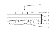
図1は、本発明の1実施例を示す真正性識別体Aの断面図である。
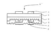
図2は、本発明の他の実施例を示す真正性識別体A´の断面図である。
Hereinafter, embodiments of the present invention will be described in detail with reference to the drawings.
FIG. 1 is a cross-sectional view of an authenticator A showing one embodiment of the present invention.
FIG. 2 is a cross-sectional view of an authenticator A ′ showing another embodiment of the present invention.
(透明基材)本発明で使用される透明基材1は、厚みを薄くすることが可能であって、機械的強度や、真正性識別体A、A´を製造する際の加工に耐える耐溶剤性および耐熱性を有するものが好ましい。使用目的にもよるので、限定されるものではないが、フィルム状もしくはシート状のプラスチックが好ましい。 (Transparent Substrate) The transparent substrate 1 used in the present invention can be reduced in thickness, and can withstand mechanical strength and processing when manufacturing authenticity identifiers A and A ′. Those having solvent resistance and heat resistance are preferred. Since it depends on the purpose of use, it is not limited, but a film-like or sheet-like plastic is preferable.
例えば、ポリエチレンテレフタレート(PET)、ポリカーボネート、ポリビニルアルコール、ポリスルホン、ポリエチレン、ポリプロピレン、ポリスチレン、ポリアリレート、トリアセチルセルロース(TAC)、ジアセチルセルロース、ポリエチレン/ビニルアルコール等の各種のプラスチックフィルムを例示することができる。
透明基材1の厚さは、通常5〜250μmであるが、反射性薄膜層3からの回り込み光を配慮する場合には、5〜50μm、特に5〜25μmとすることが望ましい。
For example, various plastic films such as polyethylene terephthalate (PET), polycarbonate, polyvinyl alcohol, polysulfone, polyethylene, polypropylene, polystyrene, polyarylate, triacetyl cellulose (TAC), diacetyl cellulose, and polyethylene / vinyl alcohol can be exemplified. .
The thickness of the transparent substrate 1 is usually 5 to 250 μm, but when considering the sneak light from the reflective
(ホログラムレリーフを有する透明樹脂層:ホログラム形成層ともいう。)本発明のホログラム形成層2を構成するための透明な樹脂材料としては、各種の熱可塑性樹脂、熱硬化性樹脂、もしくは電離放射線硬化性樹脂を用いることができる。熱可塑性樹脂としてはアクリル酸エステル樹脂、アクリルアミド樹脂、ニトロセルロース樹脂、もしくはポリスチレン樹脂等が、また、熱硬化性樹脂としては、不飽和ポリエステル樹脂、アクリルウレタン樹脂、エポキシ変性アクリル樹脂、エポキシ変性不飽和ポリエステル樹脂、アルキッド樹脂、もしくはフェノール樹脂等が挙げられる。
(Transparent resin layer having hologram relief: also referred to as hologram forming layer) As the transparent resin material for constituting the
これらの熱可塑性樹脂および熱硬化性樹脂は、1種もしくは2種以上を使用することができる。これらの樹脂の1種もしくは2種以上は、各種イソシアネート樹脂を用いて架橋させてもよいし、あるいは、各種の硬化触媒、例えば、ナフテン酸コバルト、もしくはナフテン酸亜鉛等の金属石鹸を配合するか、または、熱もしくは紫外線で重合を開始させるためのベンゾイルパーオキサイド、メチルエチルケトンパーオキサイド等の過酸化物、ベンゾフェノン、アセトフェノン、アントラキノン、ナフトキノン、アゾビスイソブチロニトリル、もしくはジフェニルスルフィド等を配合しても良い。 These thermoplastic resins and thermosetting resins can be used alone or in combination of two or more. One or more of these resins may be cross-linked using various isocyanate resins, or various curing catalysts, for example, metal soap such as cobalt naphthenate or zinc naphthenate may be blended. Or peroxide such as benzoyl peroxide and methyl ethyl ketone peroxide for initiating polymerization with heat or ultraviolet light, benzophenone, acetophenone, anthraquinone, naphthoquinone, azobisisobutyronitrile, or diphenyl sulfide good.
また、電離放射線硬化性樹脂としては、エポキシアクリレート、ウレタンアクリレート、アクリル変性ポリエステル等を挙げることができ、このような電離放射線硬化性樹脂に架橋構造を導入するか、もしくは粘度を調整する目的で、単官能モノマーもしくは多官能モノマー、またはオリゴマー等を配合して用いてもよい。 Examples of the ionizing radiation curable resin include epoxy acrylate, urethane acrylate, acrylic-modified polyester, etc., for the purpose of introducing a crosslinked structure into such an ionizing radiation curable resin or adjusting the viscosity, A monofunctional monomer, a polyfunctional monomer, or an oligomer may be blended and used.
上記の樹脂材料を用いてホログラム形成層2を形成するには、感光性樹脂材料にホログラムの干渉露光を行なって現像することによって直接的に形成することもできるが、予め作成したレリーフホログラムもしくはその複製物、またはそれらのメッキ型等を複製用型として用い、その型面を上記の樹脂材料の層に押し付けることにより、賦型を行なうのがよい。
In order to form the
熱硬化性樹脂や電離放射線硬化性樹脂を用いる場合には、型面に未硬化の樹脂を密着させたまま、加熱もしくは電離放射線照射により、硬化を行わせ、硬化後に剥離することによって、硬化した透明な樹脂材料からなる層の片面にレリーフホログラムの微細凹凸を形成することができる。なお、同様な方法によりパターン状に形成して模様状とした回折格子を有する回折格子形成層も光回折構造として使用できる。 When thermosetting resin or ionizing radiation curable resin is used, curing is performed by heating or ionizing radiation irradiation while keeping the uncured resin in close contact with the mold surface, and then cured by peeling after curing. The fine irregularities of the relief hologram can be formed on one side of the layer made of a transparent resin material. A diffraction grating forming layer having a diffraction grating formed in a pattern by a similar method can also be used as the optical diffraction structure.
ホログラムは物体光と参照光との光の干渉による干渉縞を凹凸のレリーフ形状で記録されたもので、例えば、フレネルホログラムなどのレーザ再生ホログラム、及びレインボーホログラムなどの白色光再生ホログラム、さらに、それらの原理を利用したカラーホログラム、コンピュータジェネレーティッドホログラム(CGH)、ホログラフィック回折格子などがある。また、マシンリーダブルホログラムのように、その再生光を受光部でデータに変換し所定の情報として伝達したり、真偽判定を行うものであってもよい。 A hologram is a recording of interference fringes due to interference of light between object light and reference light in an uneven relief shape. For example, a laser reproduction hologram such as a Fresnel hologram, a white light reproduction hologram such as a rainbow hologram, There are color holograms utilizing the above principle, computer generated holograms (CGH), holographic diffraction gratings and the like. Further, like a machine readable hologram, the reproduction light may be converted into data by a light receiving unit and transmitted as predetermined information, or authenticity determination may be performed.
微細な凹凸を精密に作成するため、光学的な方法だけでなく、電子線描画装置を用いて、精密に設計されたレリーフ構造を作り出し、より精密で複雑な再生光を作り出すものであってもよい。このレリーフ形状は、ホログラムを再現もしくは再生する光もしくは光源の波長(域)と、再現もしくは再生する方向、及び強度によってその凹凸のピッチや、深さ、もしくは特定の周期的形状が設計される。凹凸のピッチ(周期)は再現もしくは再生角度に依存するが、通常0.1μm〜数μmであり、凹凸の深さは、再現もしくは再生強度に大きな影響を与える要素であるが、通常0.1μm〜1μmである。 In order to precisely create fine irregularities, not only optical methods, but also electron beam lithography equipment can be used to create precisely designed relief structures that produce more precise and complex reproduction light. Good. The relief shape is designed to have a pitch, depth, or specific periodic shape of the unevenness according to the wavelength (range) of the light or light source for reproducing or reproducing the hologram, the direction and the intensity of reproduction or reproduction. The pitch (period) of the unevenness depends on the reproduction or reproduction angle, but is usually 0.1 μm to several μm, and the depth of the unevenness is a factor that greatly affects the reproduction or reproduction intensity, but is usually 0.1 μm. ˜1 μm.
単一回折格子のように、全く同一形状の凹凸の繰り返しであるものは、隣り合う凹凸が同じ形状であればある程、反射する光の干渉度合いが増しその強度が強くなり、最大値へと収束する。回折方向のぶれも最小となる。立体像のように、画像の個々の点が焦点に収束するものは、その焦点への収束精度が向上し、再現もしくは再生画像が鮮明となる。
さらに、透明金属化合物薄膜の場合は、その薄膜の上下の面が、同一レリーフ形状であり且つ、その面と面の距離(すなわち膜厚さ)が均一であればあるほど、再現もしくは再生強度が大きくなる。
As in the case of a single diffraction grating, when the unevenness of exactly the same shape is repeated, the more the adjacent unevenness is the same, the greater the intensity of interference of the reflected light and the stronger the intensity. Converge. The blur in the diffraction direction is also minimized. When the individual points of the image converge to the focal point, such as a stereoscopic image, the convergence accuracy to the focal point is improved, and the reproduced or reproduced image becomes clear.
Furthermore, in the case of a transparent metal compound thin film, the upper and lower surfaces of the thin film have the same relief shape, and the more uniform the distance between the surfaces (that is, the film thickness), the higher the reproduction or reproduction strength. growing.
ホログラムレリーフ形状を賦形(複製ともいう)する方法は、回折格子や干渉縞が凹凸の形で記録された原版をプレス型(スタンパという)として用い、上記透明基材1及び反射性薄膜層3上に、前記原版を重ねて加熱ロールなどの適宜手段により、両者を加熱圧着することにより、原版の凹凸模様を複製することができる。形成するホログラムパターンは単独でも、複数でもよい。
The hologram relief shape is shaped (also referred to as replication) by using an original plate on which diffraction gratings and interference fringes are recorded in a concavo-convex shape as a press die (referred to as a stamper), and the transparent substrate 1 and the reflective
上記の極微細な形状を精密に再現するため、また、複製後の熱収縮などの歪みや変形を最小とするため、原版は金属を使用し、低温・高圧下で複製を行う。
原版は、Niなどの硬度の高い金属を用いる。光学的撮影もしくは、電子線描画などにより形成したガラスマスターなどの表面にCr、Ni薄膜層を真空蒸着法、スパッタリングなどにより5〜50nm形成後、Niなどを電着法(電気めっき、無電解めっき、さらには複合めっきなど)により50〜1000μm形成した後、金属を剥離することで作ることができる。
In order to accurately reproduce the above-mentioned extremely fine shape and to minimize distortion and deformation such as heat shrinkage after replication, the original plate is made of metal and replicated at low temperature and high pressure.
For the original plate, a metal having high hardness such as Ni is used. After a Cr or Ni thin film layer is formed on the surface of a glass master or the like formed by optical imaging or electron beam drawing or the like by vacuum deposition or sputtering, Ni or the like is electrodeposited (electroplating, electroless plating) Further, it can be made by peeling the metal after forming 50 to 1000 μm by composite plating or the like.
複製方式は、平板式もしくは、回転式を用い、線圧0.1トン/m〜10トン/m、複製温度は、通常60℃〜200℃とする。 The duplication method uses a flat plate type or a rotary type, the linear pressure is 0.1 ton / m to 10 ton / m, and the duplication temperature is usually 60 ° C. to 200 ° C.
(反射性薄膜層)本発明では、ホログラム形成層2のホログラムレリーフ面に、反射性薄膜層3を形成する。この薄膜層は、入射した光を反射する必要があるため、ホログラム形成層2よりも高い屈折率を有する薄膜層であれば、特に限定されない。
反射性薄膜層3としては、真空薄膜法などにより形成される金属薄膜などの金属光沢反射層、又は透明反射層のいずれでもよいが、金属光沢反射層を部分的に設けたり、透明反射層を設けた場合は、その透明反射層を通して真正性識別対象物のデザイン等を確認できるので好ましい。
(Reflective thin film layer) In the present invention, the reflective
The reflective
透明反射層としては、ほぼ無色透明な色相で、その光学的な屈折率がホログラム形成層2のそれとは異なることにより、金属光沢が無いにもかかわらず、ホログラムなどの光輝性を視認できることから、透明なホログラムを作製することができる。例えば、ホログラム形成層2よりも光屈折率の高い薄膜、例として、ZnS、TiO2、Al2O3、Sb2S3、SiO、SnO2、ITOなどがある。
As a transparent reflective layer, since the optical refractive index is different from that of the
好ましくは、金属酸化物又は窒化物であり、具体的には、Be、Mg、Ca、Cr、Mn、Cu、Ag、Al、Sn、In、Te、Ti、Fe、Co、Zn、Ge、Pb、Cd、Bi、Se、Ga、Rb、Sb、Pb、Ni、Sr、Ba、La、Ce、Auなどの酸化物又は窒化物他はそれらを2種以上を混合したものなどが例示できる。またアルミニウムなどの一般的な光反射性の金属薄膜も、厚みが20nm以下になると、透明性が出てきて透明反射層として使用できる。 Preferably, it is a metal oxide or nitride, specifically, Be, Mg, Ca, Cr, Mn, Cu, Ag, Al, Sn, In, Te, Ti, Fe, Co, Zn, Ge, Pb. Cd, Bi, Se, Ga, Rb, Sb, Pb, Ni, Sr, Ba, La, Ce, Au, and other oxides or nitrides, and the like can be exemplified by a mixture of two or more thereof. Also, a general light-reflective metal thin film such as aluminum can be used as a transparent reflective layer when it has a thickness of 20 nm or less and becomes transparent.
透明金属化合物の形成は、金属の薄膜と同様、ホログラム形成層2のホログラムレリーフ面に、10〜2000nm程度、好ましくは20〜1000nmの厚さになるよう、蒸着、スパッタリング、イオンプレーティング、CVD(化学蒸着法)などの真空薄膜法などにより設ければよい。
The transparent metal compound is formed on the hologram relief surface of the
(コレステリック液晶)本発明に用いられるコレステリック液晶層4は、光選択反射性を有するものであればよく、さらに、観察側からの入射光に対して左円偏光もしくは右円偏光のいずれか一方を反射する光選択反射性を有するものであってもよい。また、これらのものを組み合わせて適用して、判定方法を複雑なものとし、より高度な真正性識別体とすることもできる。
(Cholesteric Liquid Crystal) The cholesteric
コレステリック液晶としては、コレステロールのハロゲン化物、モノカルボン酸コレステロールエステル、モノカルボン酸シトステロールエステル、安息香酸誘導体のコレスタノールエステル、二塩基酸ジコレステリルエステル、主鎖型液晶高分子化合物、側鎖型液晶高分子化合物、剛直主鎖型液晶高分子化合物などが挙げられる。 Cholesteric liquid crystals include cholesterol halides, monocarboxylic acid cholesterol esters, monocarboxylic acid sitosterol esters, benzoic acid derivative cholestanol esters, dibasic acid dicholesteryl esters, main chain liquid crystal polymer compounds, side chain liquid crystal polymers Examples thereof include molecular compounds and rigid main chain type liquid crystal polymer compounds.
より具体的には、例えばコレステリルクロライド、コレステリルアセテート、コレステリルノナノエート、炭酸メチルコレステロール、炭酸エチルコレステロール、コレステリルp−メトキシベンゾエート、シトステロイルベンゾエート、シトステロイルp−メチルベンゾエート、コレスタニルベンゾエート、10、12−ドコサジインジカルボン酸ジコレステリルエステル、8、12−エイコサジカルボン酸ジコレステリルエステル、10、12−ペンタコサジインジカルボン酸ジコレステリルエステル、ドデカジカルボン酸ジコレステリルエステル、12、14−ヘキサコサジインジカルボン酸ジコレステリルエステル、4−(7−コレステリルオキシカルボニルヘプチルオキシ)フェノキシオクタン酸コレステリルエステル、L−グルタミン酸−γ−ベンジル/L−グルタミン酸−γ−ドデシル共重合体などがある。 More specifically, for example, cholesteryl chloride, cholesteryl acetate, cholesteryl nonanoate, methyl carbonate, ethyl cholesterol, cholesteryl p-methoxybenzoate, sitosteroyl benzoate, sitosteroyl p-methyl benzoate, cholestanyl benzoate, 10, 12- Docosadiin dicarboxylic acid dicholesteryl ester, 8,12-eicosadicarboxylic acid dicholesteryl ester, 10,12-pentacosadiin dicarboxylic acid dicholesteryl ester, dodecadicarboxylic acid dicholesteryl ester, 12,14-hexacosadiin dicarboxylic acid Dicholesteryl ester, 4- (7-cholesteryloxycarbonylheptyloxy) phenoxyoctanoic acid cholesteryl ester, L-glu Min acid -γ- benzyl / L-glutamate -γ- dodecyl copolymers and the like.
さらに、コレステリルホルメート、コレステリルアセテート、コレステリルプロピオネート、コレステリルブチレート、コレステリルペンタネート、コレステリルヘキサネート、コレステリルヘプタネート、コレステリルオクタネート、コレステリルノナノエート、コレステリルデカネート、コレステリルドデカネート(コレステリルラウレート)、コレステリルミリステート、コレステリルパルミテート、コレステリルステアレート、コレステリルオレエート、コレステリルオレイルカーボネート、コレステリルリノレート、コレステリル12−ヒドロキシステアレート、コレステリルメルカプタン、コレステロールクロライド、コレステリルフルオライド、コレステリルブロマイド、コレステリルアイオダイド等を挙げることができる。 Further, cholesteryl formate, cholesteryl acetate, cholesteryl propionate, cholesteryl butyrate, cholesteryl pentanate, cholesteryl hexanate, cholesteryl heptanoate, cholesteryl octanate, cholesteryl nonanoate, cholesteryl decanate, cholesteryl decanate (cholesteryl laurate) Cholesteryl myristate, cholesteryl palmitate, cholesteryl stearate, cholesteryl oleate, cholesteryl oleyl carbonate, cholesteryl linoleate, cholesteryl 12-hydroxystearate, cholesteryl mercaptan, cholesterol chloride, cholesteryl fluoride, cholesteryl bromide, cholesteryl iodide, etc. Can be mentioned.
好ましくは、アルキルコレステロール(例えばコレステロールナノエート)およびコレステリルハライド(例えばコレステロールクロライド)コレステリルオレイルカーボネート3種の混合物が挙げられ、これらの3つのタイプの液晶は常温で使用できるように混合して用いられるのが一般的である。
尚、ここに示す化合物に限定されるものではなく、またこれらのコレステリック液晶化合物は、1種または2種以上混合して用いることができる。
Preferably, a mixture of three kinds of alkylcholesterol (for example, cholesterol nanoate) and cholesteryl halide (for example, cholesterol chloride) cholesteryl oleyl carbonate is used, and these three types of liquid crystals are used so as to be used at room temperature. Is common.
In addition, it is not limited to the compound shown here, Moreover, these cholesteric liquid crystal compounds can be used 1 type or in mixture of 2 or more types.
ネマチック液晶化合物にカイラル化合物を加えてコレステリック液晶とするものとしては、液晶化合物として、4−置換安息香酸4’−置換フェニルエステル、4−置換シクロヘキサンカルボン酸4’−置換フェニルエステル、4−置換シクロヘキサンカルボン酸4’−置換ビフェニルエステル、4−(4−置換シクロヘキサンカルボニルオキシ)安息香酸4’−置換フェニルエステル、4−(4−置換シクロヘキシル)安息香酸4’−置換フェニルエステル、4−(4−置換シクロヘキシル)安息香酸4’−置換シクロヘキシルエステル、4−置換4’−置換ビフェニル、4−置換フェニル4’−置換シクロヘキサン、4’−置換シクロヘキサン、2−(4−置換フェニル)−5−置換ピリジン等、例えば、「パリオカラーLC242」(BASF社製)等が用いられる。
As a liquid crystal compound in which a chiral compound is added to a nematic liquid crystal compound, 4-substituted
特に好ましくは、少なくとも分子の一方の末端にシアノ基又はフッ素原子を有する液晶化合物を用い、これらの液晶化合物にそれぞれ好適な各種のカイラル剤を加えたものが用いられる。カイラル化合物としては、「CB−15」、「C−15」(以上、BDH社製)、「CM−21」、「CM−22」、「CM−19」、「CM−20」、「CM」(以上、チッソ社製)、「S1082」、「S−811」、「R−811」(以上、メルク社製)、「パリオカラーLC756」(BASF社製)等を挙げることができる。 Particularly preferably, a liquid crystal compound having a cyano group or a fluorine atom at least at one end of the molecule is used, and various suitable chiral agents are added to these liquid crystal compounds. As the chiral compound, “CB-15”, “C-15” (manufactured by BDH), “CM-21”, “CM-22”, “CM-19”, “CM-20”, “CM” (Above, manufactured by Chisso Corporation), "S1082", "S-811", "R-811" (above, manufactured by Merck), "Palio Color LC756" (produced by BASF), and the like.
また、有機合成によって得られるネマチック液晶の末端基に不斉炭素を有する基を導入したコレステロール基を持たないコレステリック液晶や、コレステロール誘導体にシッフ系ネマチック液晶を加えた混合液晶も用いられる。さらには、天然コレステロールのハロゲン置換物、エステル化物(コレステリルベンゾエート、コレステリルクロライド、コレステリルオリエート、コレステリルノナノエート等も好適である。 Further, a cholesteric liquid crystal having no cholesterol group in which a group having an asymmetric carbon is introduced into a terminal group of a nematic liquid crystal obtained by organic synthesis, or a mixed liquid crystal in which a Schiff nematic liquid crystal is added to a cholesterol derivative is also used. Furthermore, halogen substitution products and esterified products of natural cholesterol (cholesteryl benzoate, cholesteryl chloride, cholesteryl oleate, cholesteryl nonanoate, and the like are also suitable.
これらのコレステリック液晶を設ける方法としては、溶剤系、水系、無溶剤系として、通常の印刷方式、コーティング方式を用いて形成することができる。より好ましくは、黒色パターン層形成方法と同一の手段を用いることにより、その形成位置の同調性を高めることができる。同一パターンを形成する場合は、製版方式も同一とすることができる。特に黒色パターン層を透明基材に設けた後は、この位置をタイミングマーク(印刷位置決め用の目印)として、液晶層の形成やホログラムレリーフ複製をすることもできる。 As a method for providing these cholesteric liquid crystals, they can be formed using a normal printing method or coating method as a solvent-based, water-based, or solvent-free system. More preferably, by using the same means as the method for forming the black pattern layer, the synchronism of the formation position can be enhanced. When the same pattern is formed, the plate making method can be the same. In particular, after the black pattern layer is provided on the transparent substrate, this position can be used as a timing mark (print positioning mark) to form a liquid crystal layer or to reproduce a hologram relief.
また液晶をゼラチン他樹脂膜等でカプセル化したインキを用いて形成してもよい。カプセル化したものは、その製造時の作業性だけでなく、物理特性(強靭性、耐摩耗性、耐熱性等)に優れるとともに、液晶の染み出し等の不具合を防止し、本発明の用途において要求される衛生面で特に好適である。 Alternatively, the liquid crystal may be formed using an ink encapsulated with a resin film such as gelatin. The encapsulated product has excellent physical properties (toughness, wear resistance, heat resistance, etc.) as well as workability at the time of manufacture, and prevents problems such as liquid seepage, and is used in the present invention. It is particularly suitable for the required hygiene.
コレステリック液晶層4の形状、厚さは、真正性識別体の使用目的に応じて適宜最適なものとする必要があるが、目視できる通常の大きさ、形状のものから、バーコード等の機械読取に用いるもの、さらには、マイクロ文字のように隠し文字として数十μmとすることもできるため、選択的反射性を維持した上で、個々に対応した厚さ、すなわち数μm〜50μmのうち、最適なものとする。
The shape and thickness of the cholesteric
上記コレステリック液晶層4を設ける際、予め以下の配向膜を設ける等の配向処理を施しても良い。配向膜は、ポリビニルアルコール樹脂(PVA)、ポリイミド樹脂等の一般に配向膜として使用し得るものであれば、いずれでもよい。配向膜は、これらの樹脂の溶剤溶液を、コレステリック液晶層4を形成する層の表面に適宜な塗布法により塗布し、乾燥させた後に、布、ブラシ等を用いて摩擦するラビングを行なって形成する。
When the cholesteric
(黒色パターン層)本発明では、ホログラム形成層2のホログラムレリーフ面に、上記コレステリック液晶層4と少なくとも相対する位置に黒色パターン層5を形成する。
このホログラム形成層2と黒色パターン層5の界面反射を発生させないためには、ホログラム形成層2と黒色パターン層5を構成する樹脂層に同一の樹脂を使用するか、もしくは同一系の樹脂もしくは他の樹脂であってもその屈折率が同一もしくは、その差が0.05以内のものを使用する。
(Black Pattern Layer) In the present invention, the
In order not to generate interface reflection between the
すなわち、ポリメチルメタクリレート(屈折率n=1.49)、ポリメチルアクリレート(n=1.47)、ポリベンジルメタクリレート(n=1.57)、ポリブチルアクリレート(n=1.44)、ポリイソブチルアクリレート(n=1.48)、硝酸セルロース(n=1.54)、メチルセルロース(n=1.50)、セルロース・アセテートプロピオネート(n=1.47)、ポリスチレン(n=1.60)、ポリエチレンテレフタレート(n=1.64)、ポリ酢酸ビニル(n=1.47)、ポリ塩化ビニル・酢酸ビニル(n=1.54)、メラミン樹脂(n=1.56)、エポキシ樹脂(n=1.61)、フェノール樹脂(n=1.60)等もしくは、この混合体等を適宜用いることができる。 That is, polymethyl methacrylate (refractive index n = 1.49), polymethyl acrylate (n = 1.47), polybenzyl methacrylate (n = 1.57), polybutyl acrylate (n = 1.44), polyisobutyl Acrylate (n = 1.48), cellulose nitrate (n = 1.54), methylcellulose (n = 1.50), cellulose acetate propionate (n = 1.47), polystyrene (n = 1.60) , Polyethylene terephthalate (n = 1.64), polyvinyl acetate (n = 1.47), polyvinyl chloride / vinyl acetate (n = 1.54), melamine resin (n = 1.56), epoxy resin (n = 1.61), phenol resin (n = 1.60), etc., or a mixture thereof can be used as appropriate.
黒色顔料としては、観察する光(可視光)の全波長領域に対する吸収性を有する顔料であればいずれも使用できるが、代表的には微粒子カーボンブラックが使用できる。
カーボンブラックには、三菱化学製HCF2400B、HCF2700B、MCF900、RCF45等、デグサエボニック社製カラーブラックFW200、スペシャルブラック250等、旭カーボン社製サンブラック700、サンブラック900、ケッチェンブラック社製EC−600等が使用できる。
As the black pigment, any pigment can be used as long as it has an absorptivity for the entire wavelength region of light to be observed (visible light). Typically, fine carbon black can be used.
Carbon black includes Mitsubishi Chemical HCF2400B, HCF2700B, MCF900, RCF45, etc., Degussa Evonik Color Black FW200, Special Black 250, Asahi Carbon Sun Black 700, Sun Black 900, Ketjen Black EC-600 Etc. can be used.
粒径は、0.01〜0.1μmのものが好適だが、二次凝集しやすく、再分散処理等を施す必要がある。添加量は、オフセット印刷方式、グラビア印刷方式等、適宜な形成パタ形成方法で形成する厚さとのバランスで決められるが、通常10%〜50%添加が好適であり、適宜な溶剤に溶かして、2〜20μm厚さに形成する。 A particle size of 0.01 to 0.1 μm is preferable, but secondary aggregation tends to occur, and redispersion treatment or the like needs to be performed. The addition amount is determined by the balance with the thickness formed by an appropriate formation pattern formation method such as an offset printing method, a gravure printing method, etc., but usually 10% to 50% addition is preferable, dissolved in an appropriate solvent, It is formed to a thickness of 2 to 20 μm.
黒色パターン形成後、表面粗さ1.0μm以上の凹凸を有する金属製スタンパにて加熱プレスすることで、黒色パターンの表面を粗面化することができる。また、この黒色顔料に加えて、粒径1.0μm以上の炭酸カルシウム、二酸化チタン等の体質顔料を使用することでも、黒色パターン層を粗面化することができる。 After the black pattern is formed, the surface of the black pattern can be roughened by heating and pressing with a metal stamper having irregularities with a surface roughness of 1.0 μm or more. In addition to this black pigment, the black pattern layer can also be roughened by using extender pigments such as calcium carbonate and titanium dioxide having a particle size of 1.0 μm or more.
但し、本発明の真正性識別体の第3の態様に用いるカーボンフ゛ラックは、東海カーボン社製親水性アクアブラック162、アクアブラック0001等のように、敢て凝集させて、粒径を1μm以上としたものが好適である。使用する樹脂系、形成方法等は上記したものを用いることができる。但し、形成厚さは、採用する粒径と同等がそれより薄くすることで、粗面化効果を高めることができる。 However, the carbon black used in the third embodiment of the authenticity identifier of the present invention is agglomerated and has a particle size of 1 μm or more, such as hydrophilic aqua black 162, aqua black 0001, etc. manufactured by Tokai Carbon Co., Ltd. That is suitable. As the resin system and the forming method used, those described above can be used. However, the effect of roughening can be enhanced by making the formation thickness equal to the grain size to be employed, or thinner.
また、本発明の真正性識別体にさらに、粘着剤を施してラベルとしたり、接着剤を施して転写シートとすることもできる。
その場合、粘着剤としては、従来公知の溶剤系及び水系のいずれの粘着剤、例えば、酢酸ビニル樹脂、アクリル樹脂、酢酸ビニル−アクリル共重合体、酢酸ビニル−塩化ビニル共重合体、エチレン−酢酸ビニル共重合体、ポリウレタン樹脂や、天然ゴム、クロロプレンゴムなどのゴム系樹脂などが挙げられる。
Further, the authenticity identification body of the present invention can be further labeled with a pressure-sensitive adhesive or a transfer sheet by applying an adhesive.
In this case, as the pressure-sensitive adhesive, any conventionally known solvent-based or water-based pressure-sensitive adhesives such as vinyl acetate resin, acrylic resin, vinyl acetate-acrylic copolymer, vinyl acetate-vinyl chloride copolymer, ethylene-acetic acid are used. Examples include vinyl copolymers, polyurethane resins, and rubber resins such as natural rubber and chloroprene rubber.
自然にやさしい材料構成とするために、特に、天然ゴムを主成分とするラテックス、それを変性したもの、特に天然ゴムにスチレン特にメタクリルさんメチルとをグラフト重合させて得た天然ゴムラテックス等の天然素材から作製されたものを用いても良く、形成厚さ、形成方法等は適宜選択する。 Natural latex such as natural rubber latex, natural rubber latex obtained by graft polymerization of natural rubber with styrene, especially methacrylic acid methyl, in particular, to make natural material composition What was produced from the raw material may be used and formation thickness, a formation method, etc. are selected suitably.
また、接着剤としては、接着剤としては、種々の物品に対する接着性を確保するためのものであるので、反射性薄膜層4との接着性がよく、被着体と強固に接着できるものが好ましい。具体的には、塩化ビニル系樹脂、酢酸ビニル系樹脂、塩化ビニル−酢酸ビニル共重合体樹脂、アクリル系樹脂、ポリエステル系樹脂、ポリウレタン系樹脂、ポリアミド系樹脂、ゴム変性物などが挙げられ、これらの中から適するものを適宜選択して使用でき、また、これらは単体、もしくは2種以上の混合系で、更に必要に応じてハードレジンや可塑剤、その他の添加剤を加えて使用することができ、形成厚さ、形成方法等は適宜選択する。
Moreover, as an adhesive agent, since it is for ensuring the adhesiveness with respect to various articles | goods, what has good adhesiveness with the reflective
(実施例1)
透明基材1として、25μmのPETフィルムの表面に、グラビア印刷により厚さ5μmのコレスチック液晶層4を“H文字”形状に形成した後、紫外線硬化させた。
・<コレステリック液晶組成物>
バイカラーLC242 37質量部
バイカラーLC756 2質量部
紫外線重合開始剤 1質量部
トルエン 60質量部
Example 1
As a transparent substrate 1, a cholestic
・ <Cholesteric liquid crystal composition>
Bicolor LC242 37 parts by
PETフィルムの上記印刷を行なった面とは反対側の面にメラミン樹脂組成物(n=1.56)を塗布し、レリーフホログラムの複製用型の型面を、接触させたまま加熱硬化させることにより、レリーフホログラムの形成を行ない、厚さ20μmのホログラム形成層2を得た。その上に、下記組成の黒色パターン層4を上記グラビア方式、同一グラビア版を使用して、厚さ5μmの黒色パターン層4を得た。
Applying a melamine resin composition (n = 1.56) to the surface of the PET film opposite to the surface on which the above printing has been performed, and heat curing the mold surface of the relief hologram duplication mold in contact. Thus, a relief hologram was formed, and a
・<黒色パターン組成物>
上記メラミン樹脂 30質量部
トーカブラック8500 10質量部
体質顔料 5質量部
トルエン 55質量部
・ <Black pattern composition>
30 parts by mass of the melamine resin Toka Black 8500 10 parts by
このレリーフホログラムの賦型された面及び黒色パターン層4面上に、ALを真空蒸着して、厚みが100nmの反射性薄膜層3を形成して、真偽判定用識別体Aを得た。
On the surface on which the relief hologram is shaped and on the surface of the
得られた真正性識別体を観察側から眺めると、ホログラム再生像と、黒色パターン層の文字“H”が見え、観察する角度を変えると、黒色パターン文字“H”が「緑色」に変わり、はっきりと認識できた。 When the obtained authenticity identifier is viewed from the observation side, the hologram reproduction image and the letter “H” in the black pattern layer are seen. When the observation angle is changed, the black pattern letter “H” changes to “green”. It was clearly recognized.
(実施例2)
体質顔料として、平均粒径1.0μmの炭酸カルシウムを同量使用したこと以外は、実施例1と同一とし、実施例2を得た。得られた真正性識別体を観察側から眺めると、ホログラム再生像と、黒色パターンの文字“H”が見え、観察する角度を変えると、黒色パターン文字“H”が「緑色」に変わり、はっきりと認識できた。特に、文字“H”の隅々まで色がでており、反射性薄膜層からの反射光は見られなかった。
(Example 2)
Example 2 was obtained in the same manner as in Example 1 except that the same amount of calcium carbonate having an average particle diameter of 1.0 μm was used as the extender pigment. When the obtained authenticity identifier is viewed from the observation side, the hologram reproduction image and the black pattern letter “H” can be seen, and when the observation angle is changed, the black pattern letter “H” changes to “green”, clearly I was able to recognize. In particular, the color was shown to every corner of the letter “H”, and no reflected light from the reflective thin film layer was seen.
(実施例3)
ホログラム形成層2にポリメチルメタクリレート(n=1.49)を使用し、黒色パターン層5にもポリメチルメタクリレート(n=1.49)を使用し、且つカーボンブラックとして、東海カーボン社製グラッシーカーボン(粒径1.0μm)を持ちいて、形成厚さを1.0μmとした以外は、実施例1と同様として、実施例3を得た。得られた真正性識別体を観察側から眺めると、ホログラム再生像と、黒色パターンの文字“H”が見え、観察する角度を変えると、黒色パターン文字“H”が「緑色」に変わり、はっきりと認識できた。特に、文字“H”の隅々まで色がでており、界面反射からの反射光は全く見られなかった。
(Example 3)
Polymethyl methacrylate (n = 1.49) is used for the
(比較例)
ホログラム形成層2にメラミン樹脂(n=1.56)を使用し、黒色パターン層5にポリメチルメタクリレート(n=1.49)を使用した以外は、実施例1と同様として、比較例を得た。得られた真正性識別体を観察側から眺めると、ホログラム再生像と、黒色パターンの文字“H”が見え、観察する角度を変えると、黒色パターン文字“H”が「緑色」に変わったものの、戻り光により。文字“H”の隅々までは、はっきりと認識できなかった。
(Comparative example)
A comparative example was obtained in the same manner as in Example 1 except that melamine resin (n = 1.56) was used for
A、A´ 真正性識別体
1 透明基材
2 ホログラムレリーフを有する透明樹脂層(ホログラム形成層)
3 反射性薄膜層
4 コレステリック液晶層
5 黒色パターン層
6 粗面化された界面
A, A ′ Authenticity discriminator 1
3 Reflective
Claims (3)
Priority Applications (1)
| Application Number | Priority Date | Filing Date | Title |
|---|---|---|---|
| JP2008164343A JP5140815B2 (en) | 2008-06-24 | 2008-06-24 | Authenticity identifier |
Applications Claiming Priority (1)
| Application Number | Priority Date | Filing Date | Title |
|---|---|---|---|
| JP2008164343A JP5140815B2 (en) | 2008-06-24 | 2008-06-24 | Authenticity identifier |
Publications (2)
| Publication Number | Publication Date |
|---|---|
| JP2010005796A true JP2010005796A (en) | 2010-01-14 |
| JP5140815B2 JP5140815B2 (en) | 2013-02-13 |
Family
ID=41586844
Family Applications (1)
| Application Number | Title | Priority Date | Filing Date |
|---|---|---|---|
| JP2008164343A Active JP5140815B2 (en) | 2008-06-24 | 2008-06-24 | Authenticity identifier |
Country Status (1)
| Country | Link |
|---|---|
| JP (1) | JP5140815B2 (en) |
Cited By (1)
| Publication number | Priority date | Publication date | Assignee | Title |
|---|---|---|---|---|
| JP2010072385A (en) * | 2008-09-19 | 2010-04-02 | Dainippon Printing Co Ltd | Authenticity identifying article |
Citations (4)
| Publication number | Priority date | Publication date | Assignee | Title |
|---|---|---|---|---|
| JP2000321960A (en) * | 1999-03-08 | 2000-11-24 | Dainippon Printing Co Ltd | Self-adhesive film for forming hologram, dry plate for photographing hologram, and image forming method using them |
| JP2006153990A (en) * | 2004-11-25 | 2006-06-15 | Dainippon Printing Co Ltd | Authenticity identifying body and authenticity identifiable base material |
| JP2007003673A (en) * | 2005-06-22 | 2007-01-11 | Toppan Printing Co Ltd | Forgery prevention medium, forgery prevention body used for the same and forgery prevention body transfer foil |
| JP2007090538A (en) * | 2005-09-27 | 2007-04-12 | Dainippon Printing Co Ltd | Medium for judging authenticity |
-
2008
- 2008-06-24 JP JP2008164343A patent/JP5140815B2/en active Active
Patent Citations (4)
| Publication number | Priority date | Publication date | Assignee | Title |
|---|---|---|---|---|
| JP2000321960A (en) * | 1999-03-08 | 2000-11-24 | Dainippon Printing Co Ltd | Self-adhesive film for forming hologram, dry plate for photographing hologram, and image forming method using them |
| JP2006153990A (en) * | 2004-11-25 | 2006-06-15 | Dainippon Printing Co Ltd | Authenticity identifying body and authenticity identifiable base material |
| JP2007003673A (en) * | 2005-06-22 | 2007-01-11 | Toppan Printing Co Ltd | Forgery prevention medium, forgery prevention body used for the same and forgery prevention body transfer foil |
| JP2007090538A (en) * | 2005-09-27 | 2007-04-12 | Dainippon Printing Co Ltd | Medium for judging authenticity |
Cited By (1)
| Publication number | Priority date | Publication date | Assignee | Title |
|---|---|---|---|---|
| JP2010072385A (en) * | 2008-09-19 | 2010-04-02 | Dainippon Printing Co Ltd | Authenticity identifying article |
Also Published As
| Publication number | Publication date |
|---|---|
| JP5140815B2 (en) | 2013-02-13 |
Similar Documents
| Publication | Publication Date | Title |
|---|---|---|
| JP4390265B2 (en) | Authenticity determination medium, authenticity determination medium label, authenticity determination medium transfer sheet, authenticity determination sheet, and authenticity determination information recording medium | |
| JP2010194722A (en) | Patch transfer medium | |
| JP2003185835A (en) | Authenticity identifying body and transfer sheet with authenticity identifying structure | |
| JP5083140B2 (en) | Authenticity identifier | |
| JP2005091786A (en) | Medium for judging authenticity, medium label for judging authenticity, medium transfer sheet for judging authenticity, sheet capable of judging authenticity and information recording body capable of judging authenticity | |
| JP3984470B2 (en) | Authenticity discriminator, authenticity discrimination tool, and combinations thereof, and authenticity discrimination method | |
| JP4743448B2 (en) | Authenticity discriminator and authenticity discriminating structure transfer sheet | |
| JP5332325B2 (en) | Hologram sheet | |
| JP2005088381A (en) | Medium for judging authenticity, medium label for judging authenticity, transfer sheet of medium for judging authenticity, sheet enabling judgment of authenticity and information recorded body enabling judgment of authenticity | |
| JP2007181941A (en) | Magnetic transferring foil | |
| JP2005301093A (en) | Medium for determining authenticity, medium label for determining authenticity, medium transfer sheet for determining authenticity, sheet capable of determining authenticity and information recording body capable of determining authenticity | |
| JP5476781B2 (en) | Transfer sheet for authenticity identification | |
| JP2009166319A (en) | Method for manufacturing intermediate transfer recording medium, method for recording information using it, and method for manufacturing information recording body | |
| JP5140815B2 (en) | Authenticity identifier | |
| JP5083260B2 (en) | Authenticity identifier | |
| JP5359250B2 (en) | Method for manufacturing patch transfer medium | |
| JP2010173203A (en) | Patch transfer medium | |
| JP2010072386A (en) | Authenticity identifying article | |
| JP5407292B2 (en) | Patch transfer media | |
| JP2010120201A (en) | Patch transfer medium | |
| JP5282514B2 (en) | Authenticity identifier | |
| JP2010145672A (en) | Authenticity identification material | |
| JP5644077B2 (en) | Authenticity identifier, authenticity determination sheet, and authenticity determination method | |
| JP2010107748A (en) | Authenticity identification material | |
| JP2010079308A (en) | Medium for determining authenticity, medium label for determining authenticity, medium transfer sheet for determining authenticity, sheet determining authenticity, and information recording medium determining authenticity |
Legal Events
| Date | Code | Title | Description |
|---|---|---|---|
| A621 | Written request for application examination |
Free format text: JAPANESE INTERMEDIATE CODE: A621 Effective date: 20110427 |
|
| A977 | Report on retrieval |
Free format text: JAPANESE INTERMEDIATE CODE: A971007 Effective date: 20120815 |
|
| A131 | Notification of reasons for refusal |
Free format text: JAPANESE INTERMEDIATE CODE: A131 Effective date: 20120821 |
|
| A521 | Written amendment |
Free format text: JAPANESE INTERMEDIATE CODE: A523 Effective date: 20120926 |
|
| TRDD | Decision of grant or rejection written | ||
| A01 | Written decision to grant a patent or to grant a registration (utility model) |
Free format text: JAPANESE INTERMEDIATE CODE: A01 Effective date: 20121009 |
|
| A01 | Written decision to grant a patent or to grant a registration (utility model) |
Free format text: JAPANESE INTERMEDIATE CODE: A01 |
|
| A61 | First payment of annual fees (during grant procedure) |
Free format text: JAPANESE INTERMEDIATE CODE: A61 Effective date: 20121022 |
|
| FPAY | Renewal fee payment (event date is renewal date of database) |
Free format text: PAYMENT UNTIL: 20151130 Year of fee payment: 3 |
|
| R150 | Certificate of patent or registration of utility model |
Ref document number: 5140815 Country of ref document: JP Free format text: JAPANESE INTERMEDIATE CODE: R150 Free format text: JAPANESE INTERMEDIATE CODE: R150 |