JP2010005592A - Catalyst for cleaning exhaust - Google Patents
Catalyst for cleaning exhaust Download PDFInfo
- Publication number
- JP2010005592A JP2010005592A JP2008170859A JP2008170859A JP2010005592A JP 2010005592 A JP2010005592 A JP 2010005592A JP 2008170859 A JP2008170859 A JP 2008170859A JP 2008170859 A JP2008170859 A JP 2008170859A JP 2010005592 A JP2010005592 A JP 2010005592A
- Authority
- JP
- Japan
- Prior art keywords
- catalyst layer
- upstream
- downstream
- catalyst
- thickness
- Prior art date
- Legal status (The legal status is an assumption and is not a legal conclusion. Google has not performed a legal analysis and makes no representation as to the accuracy of the status listed.)
- Granted
Links
- 239000003054 catalyst Substances 0.000 title claims abstract description 357
- 238000004140 cleaning Methods 0.000 title abstract 3
- 238000011144 upstream manufacturing Methods 0.000 claims abstract description 85
- 239000002131 composite material Substances 0.000 claims description 20
- 229910052697 platinum Inorganic materials 0.000 abstract description 7
- 229910052703 rhodium Inorganic materials 0.000 abstract description 6
- 238000010792 warming Methods 0.000 abstract 1
- 239000010410 layer Substances 0.000 description 253
- 238000000746 purification Methods 0.000 description 76
- 239000007789 gas Substances 0.000 description 70
- 239000004215 Carbon black (E152) Substances 0.000 description 48
- 229930195733 hydrocarbon Natural products 0.000 description 48
- 150000002430 hydrocarbons Chemical class 0.000 description 48
- 239000010948 rhodium Substances 0.000 description 38
- BASFCYQUMIYNBI-UHFFFAOYSA-N platinum Substances [Pt] BASFCYQUMIYNBI-UHFFFAOYSA-N 0.000 description 34
- KDLHZDBZIXYQEI-UHFFFAOYSA-N palladium Substances [Pd] KDLHZDBZIXYQEI-UHFFFAOYSA-N 0.000 description 33
- 229910052751 metal Inorganic materials 0.000 description 29
- 239000002184 metal Substances 0.000 description 29
- 239000000463 material Substances 0.000 description 23
- 239000000758 substrate Substances 0.000 description 23
- 230000000052 comparative effect Effects 0.000 description 17
- 230000000694 effects Effects 0.000 description 17
- 229910018072 Al 2 O 3 Inorganic materials 0.000 description 16
- 239000002002 slurry Substances 0.000 description 14
- 239000000843 powder Substances 0.000 description 12
- QVGXLLKOCUKJST-UHFFFAOYSA-N atomic oxygen Chemical compound [O] QVGXLLKOCUKJST-UHFFFAOYSA-N 0.000 description 8
- 229910000510 noble metal Inorganic materials 0.000 description 8
- 239000001301 oxygen Substances 0.000 description 8
- 229910052760 oxygen Inorganic materials 0.000 description 8
- 229910021193 La 2 O 3 Inorganic materials 0.000 description 7
- 230000003197 catalytic effect Effects 0.000 description 7
- 239000000243 solution Substances 0.000 description 7
- XLYOFNOQVPJJNP-UHFFFAOYSA-M hydroxide Chemical compound [OH-] XLYOFNOQVPJJNP-UHFFFAOYSA-M 0.000 description 6
- 229910052746 lanthanum Inorganic materials 0.000 description 6
- 239000000203 mixture Substances 0.000 description 6
- 230000003647 oxidation Effects 0.000 description 6
- 238000007254 oxidation reaction Methods 0.000 description 6
- 238000001179 sorption measurement Methods 0.000 description 6
- XLYOFNOQVPJJNP-UHFFFAOYSA-N water Substances O XLYOFNOQVPJJNP-UHFFFAOYSA-N 0.000 description 6
- 238000009792 diffusion process Methods 0.000 description 5
- 229910052761 rare earth metal Inorganic materials 0.000 description 5
- 229910002651 NO3 Inorganic materials 0.000 description 4
- NHNBFGGVMKEFGY-UHFFFAOYSA-N Nitrate Chemical compound [O-][N+]([O-])=O NHNBFGGVMKEFGY-UHFFFAOYSA-N 0.000 description 4
- 238000010521 absorption reaction Methods 0.000 description 4
- PNEYBMLMFCGWSK-UHFFFAOYSA-N aluminium oxide Inorganic materials [O-2].[O-2].[O-2].[Al+3].[Al+3] PNEYBMLMFCGWSK-UHFFFAOYSA-N 0.000 description 4
- 239000007864 aqueous solution Substances 0.000 description 4
- 239000000446 fuel Substances 0.000 description 4
- 150000002739 metals Chemical class 0.000 description 4
- NLXLAEXVIDQMFP-UHFFFAOYSA-N Ammonium chloride Substances [NH4+].[Cl-] NLXLAEXVIDQMFP-UHFFFAOYSA-N 0.000 description 3
- VHUUQVKOLVNVRT-UHFFFAOYSA-N Ammonium hydroxide Chemical compound [NH4+].[OH-] VHUUQVKOLVNVRT-UHFFFAOYSA-N 0.000 description 3
- 229910052684 Cerium Inorganic materials 0.000 description 3
- 229910052779 Neodymium Inorganic materials 0.000 description 3
- QGZKDVFQNNGYKY-UHFFFAOYSA-N ammonia Natural products N QGZKDVFQNNGYKY-UHFFFAOYSA-N 0.000 description 3
- 235000011114 ammonium hydroxide Nutrition 0.000 description 3
- 239000011230 binding agent Substances 0.000 description 3
- 230000015572 biosynthetic process Effects 0.000 description 3
- 238000006243 chemical reaction Methods 0.000 description 3
- 230000003111 delayed effect Effects 0.000 description 3
- 239000012153 distilled water Substances 0.000 description 3
- 238000001914 filtration Methods 0.000 description 3
- 230000001771 impaired effect Effects 0.000 description 3
- 229910052763 palladium Inorganic materials 0.000 description 3
- 239000002245 particle Substances 0.000 description 3
- 229920006395 saturated elastomer Polymers 0.000 description 3
- 239000003381 stabilizer Substances 0.000 description 3
- 238000003756 stirring Methods 0.000 description 3
- 238000005406 washing Methods 0.000 description 3
- 229910052727 yttrium Inorganic materials 0.000 description 3
- 229910052726 zirconium Inorganic materials 0.000 description 3
- 229910052777 Praseodymium Inorganic materials 0.000 description 2
- MCMNRKCIXSYSNV-UHFFFAOYSA-N Zirconium dioxide Chemical compound O=[Zr]=O MCMNRKCIXSYSNV-UHFFFAOYSA-N 0.000 description 2
- 229910052782 aluminium Inorganic materials 0.000 description 2
- 238000002485 combustion reaction Methods 0.000 description 2
- 229910052878 cordierite Inorganic materials 0.000 description 2
- JSKIRARMQDRGJZ-UHFFFAOYSA-N dimagnesium dioxido-bis[(1-oxido-3-oxo-2,4,6,8,9-pentaoxa-1,3-disila-5,7-dialuminabicyclo[3.3.1]nonan-7-yl)oxy]silane Chemical compound [Mg++].[Mg++].[O-][Si]([O-])(O[Al]1O[Al]2O[Si](=O)O[Si]([O-])(O1)O2)O[Al]1O[Al]2O[Si](=O)O[Si]([O-])(O1)O2 JSKIRARMQDRGJZ-UHFFFAOYSA-N 0.000 description 2
- 238000006073 displacement reaction Methods 0.000 description 2
- 239000001257 hydrogen Substances 0.000 description 2
- 229910052739 hydrogen Inorganic materials 0.000 description 2
- 238000005259 measurement Methods 0.000 description 2
- 238000005192 partition Methods 0.000 description 2
- 231100000572 poisoning Toxicity 0.000 description 2
- 230000000607 poisoning effect Effects 0.000 description 2
- 239000000126 substance Substances 0.000 description 2
- 229910052692 Dysprosium Inorganic materials 0.000 description 1
- 229910052691 Erbium Inorganic materials 0.000 description 1
- 229910052693 Europium Inorganic materials 0.000 description 1
- 229910052688 Gadolinium Inorganic materials 0.000 description 1
- 229910052689 Holmium Inorganic materials 0.000 description 1
- UFHFLCQGNIYNRP-UHFFFAOYSA-N Hydrogen Chemical compound [H][H] UFHFLCQGNIYNRP-UHFFFAOYSA-N 0.000 description 1
- 229910052765 Lutetium Inorganic materials 0.000 description 1
- GRYLNZFGIOXLOG-UHFFFAOYSA-N Nitric acid Chemical compound O[N+]([O-])=O GRYLNZFGIOXLOG-UHFFFAOYSA-N 0.000 description 1
- 229910052772 Samarium Inorganic materials 0.000 description 1
- -1 SiC Chemical compound 0.000 description 1
- 229910052771 Terbium Inorganic materials 0.000 description 1
- 229910052775 Thulium Inorganic materials 0.000 description 1
- 229910052769 Ytterbium Inorganic materials 0.000 description 1
- 230000033228 biological regulation Effects 0.000 description 1
- 239000000919 ceramic Substances 0.000 description 1
- CETPSERCERDGAM-UHFFFAOYSA-N ceric oxide Chemical compound O=[Ce]=O CETPSERCERDGAM-UHFFFAOYSA-N 0.000 description 1
- 229910000422 cerium(IV) oxide Inorganic materials 0.000 description 1
- 239000011248 coating agent Substances 0.000 description 1
- 238000000576 coating method Methods 0.000 description 1
- 238000011156 evaluation Methods 0.000 description 1
- 239000006260 foam Substances 0.000 description 1
- 150000002431 hydrogen Chemical class 0.000 description 1
- 238000004519 manufacturing process Methods 0.000 description 1
- 150000002823 nitrates Chemical class 0.000 description 1
- 229910017604 nitric acid Inorganic materials 0.000 description 1
- 230000001590 oxidative effect Effects 0.000 description 1
- MHOVAHRLVXNVSD-UHFFFAOYSA-N rhodium atom Chemical compound [Rh] MHOVAHRLVXNVSD-UHFFFAOYSA-N 0.000 description 1
- 229910052706 scandium Inorganic materials 0.000 description 1
- 239000006104 solid solution Substances 0.000 description 1
- 238000000629 steam reforming Methods 0.000 description 1
- 230000001629 suppression Effects 0.000 description 1
- 239000002344 surface layer Substances 0.000 description 1
Images


Abstract
Description
本発明は、Pt、Rh、Pdなどの貴金属触媒を用いた排ガス浄化用触媒に関する。 The present invention relates to an exhaust gas purifying catalyst using a noble metal catalyst such as Pt, Rh, or Pd.
自動車の排ガスを浄化する排ガス浄化用触媒として、Pt、Rh、Pdなどの貴金属触媒を用いたものがある。貴金属触媒のうちPt及びPdは主としてCO及びHCの酸化浄化に寄与し、Rhは主としてNOxの還元浄化に寄与する。そして、これらの貴金属触媒の性能を効果的に発揮させるために、貴金属触媒を複数層に配置した触媒が提案されている(特許文献1)。 As an exhaust gas purifying catalyst for purifying automobile exhaust gas, there is a catalyst using a noble metal catalyst such as Pt, Rh, Pd. Of the noble metal catalysts, Pt and Pd mainly contribute to the oxidation and purification of CO and HC, and Rh mainly contributes to the reduction and purification of NOx. And in order to exhibit the performance of these noble metal catalysts effectively, the catalyst which has arrange | positioned the noble metal catalyst in multiple layers is proposed (patent document 1).
ところで、近年の排ガス規制強化により、エンジン始動直後から排ガス成分の高い浄化率を達成することがもとめられている。このような要求に応ずるため、例えば、特許文献2には、モノリス担体上に、炭化水素吸着能をもつ吸着層を形成し、吸着層の表面にPt、Rh、Pdなどを含み所定の膜厚をもつ触媒層を形成した触媒が開示されている。この触媒では、触媒層を所定の厚みにすることで、内層の吸着層によるHCの吸着能と、吸着層から脱離するHCの触媒層による浄化能とのバランスを図り、コールドスタート時(エンジン始動直後)に内燃機関から多量に排出される未燃焼HC(炭化水素)を効果的に浄化するものである。
By the way, due to the recent tightening of exhaust gas regulations, it has been sought to achieve a high purification rate of exhaust gas components immediately after engine startup. In order to meet such a requirement, for example, in
また、特許文献3には、Pdを含む上流部触媒層と、上流部触媒層よりも下流側に配置されPtを含む内層及びRhを含む表層からなる下流部触媒層とからなる触媒が開示されている。この触媒では、エンジン始動時に、主に炭化水素浄化能をもつ上流部触媒層が作用し、HC浄化時に発生する反応熱によって下流部触媒層を加熱して暖機性を向上させるものである。
しかし、上記特許文献2は、HCの浄化を目的とする酸化触媒である。このため、特許文献2の触媒は、排ガス中のHC以外のNOx、COなどの排ガス成分を有効に浄化するものではない。
However,
また、特許文献3に示された触媒は、CO、HC、NOxを浄化する三元触媒であり、排ガス中に含まれている排ガス成分を有効に浄化するものである。しかし、上流部触媒層の厚みが、下流部触媒層の厚みと同じであるため、上流側触媒層の内部へのガス拡散性が低い。ゆえに、上流側触媒層の内部に担持されているPdが有効に触媒作用を発揮することができない。
The catalyst disclosed in
そこで、発明者らは、基材の表面に形成され、上流側部分にPdを含み下流側部分にPtを含む下触媒層と、下触媒層の表面に形成されRhを含む上触媒層とからなり、上触媒層のガス流れ方向の長さを下触媒層の長さよりも短くして、下触媒層の上流側部分を上触媒層から露出させた排ガス浄化用触媒を開発している。この触媒では、下触媒層の上流側部分は、上触媒層から露出しているため、上流側部分に含まれるPd全体の触媒作用を効果的に発揮させることができる。 Therefore, the inventors formed a lower catalyst layer formed on the surface of the base material and containing Pd in the upstream portion and Pt in the downstream portion, and an upper catalyst layer formed on the surface of the lower catalyst layer and containing Rh. Thus, an exhaust gas purifying catalyst has been developed in which the length of the upper catalyst layer in the gas flow direction is made shorter than the length of the lower catalyst layer, and the upstream portion of the lower catalyst layer is exposed from the upper catalyst layer. In this catalyst, since the upstream portion of the lower catalyst layer is exposed from the upper catalyst layer, the catalytic action of the entire Pd contained in the upstream portion can be effectively exhibited.
しかしながら、この触媒では、上触媒層に含まれているRhによる暖機時のNOx浄化活性が不十分である。
本発明はかかる事情に鑑みてなされたものであり、コールドスタード時に発生するHCを効果的に浄化することができ、且つ暖機時のCO、HC及びNOx浄化性能にも優れた排ガス浄化用触媒を提供することを課題とする。 The present invention has been made in view of such circumstances, and is an exhaust gas purifying catalyst that can effectively purify HC generated during cold start and is excellent in CO, HC and NOx purification performance during warm-up. It is an issue to provide.
請求項1に係る発明は、排ガスが流通するガス流路を形成する流路壁の上流側に形成された上流側触媒層と、前記流路壁の前記上流側触媒層よりも下流側に形成された下流側触媒層と、をもつ排ガス浄化用触媒であって、前記上流側触媒層は、前記下流側触媒層よりも厚みが薄く、Pdを含み、前記下流側触媒層は、前記流路壁の表面に形成されPt及びZrO2−CeO2複合酸化物を含む内触媒層と、前記内触媒層の表面に形成されRhを含む外触媒層とからなり、前記内触媒層の厚みに対する前記外触媒層の厚みの比率は1.5〜2.5であることを特徴とする。
The invention according to
請求項2に係る発明は、前記内触媒層の厚みに対する前記外触媒層の厚みの比率は1.5〜2.2であることを特徴とする。
The invention according to
請求項3に係る発明は、前記上流側触媒層の長さと前記下流側触媒層の長さとを合わせた合計長さに対する前記下流側触媒層の長さの比率は、50〜90%であることを特徴とする。
In the invention according to
前記請求項1に係る発明である排ガス浄化用触媒は、Pdを含む上流側触媒層と、内触媒層と外触媒層とからなる2層構造の下流側触媒層とをもつ。上流側触媒層では、Pdにより主として排ガス中のHCの酸化浄化が行われる。HC(炭化水素)は、分子構造が比較的大きく、上流側触媒層の内部に拡散しにくい。そこで、本発明では、上流側触媒層の厚みを、下流側触媒層の厚みよりも薄くしている。このため、上流側触媒層に比べて下流側触媒層の内部までの拡散距離が短くなる。従って、HCが拡散しやすくなり、HCの酸化浄化効率が向上する。 The exhaust gas purifying catalyst according to the first aspect of the present invention has an upstream catalyst layer containing Pd and a downstream catalyst layer having a two-layer structure including an inner catalyst layer and an outer catalyst layer. In the upstream catalyst layer, oxidation purification of HC in the exhaust gas is mainly performed by Pd. HC (hydrocarbon) has a relatively large molecular structure and is difficult to diffuse inside the upstream catalyst layer. Therefore, in the present invention, the upstream catalyst layer is made thinner than the downstream catalyst layer. For this reason, the diffusion distance to the inside of the downstream catalyst layer is shorter than that of the upstream catalyst layer. Accordingly, HC is easily diffused, and the oxidation purification efficiency of HC is improved.
下流側触媒層の外触媒層では、Rhにより主として排ガス中のNOxの還元浄化が行われる。Rhは、排ガス中の上流側触媒層で酸化浄化されなかった残存HCから、水素改質反応によって水素を発生させる。この水素の還元力によって、排ガス中のNOxが還元浄化される。 In the outer catalyst layer of the downstream catalyst layer, NOx in the exhaust gas is mainly reduced and purified by Rh. Rh generates hydrogen from the remaining HC that has not been oxidized and purified by the upstream catalyst layer in the exhaust gas through a hydrogen reforming reaction. Due to the reducing power of hydrogen, NOx in the exhaust gas is reduced and purified.
排ガス成分の中のCOは、分子構造が比較的小さく、拡散速度が比較的速い。このため、COは、下流側触媒層の内部に配置されている内触媒層に素早く拡散することができる。ゆえに、内触媒層に担持されているPtは、主としてCO及び残存CHを酸化浄化することができる。 CO in the exhaust gas component has a relatively small molecular structure and a relatively high diffusion rate. For this reason, CO can diffuse quickly into the inner catalyst layer disposed inside the downstream catalyst layer. Therefore, Pt supported on the inner catalyst layer can mainly oxidize and purify CO and residual CH.
ここで、本発明においては、内触媒層の厚みに対する外触媒層の厚みの比率は1.5〜2.5である。このため、内触媒層に比べて外触媒層が1.5〜2.5倍の範囲で厚いため、外触媒層に担持されているRhは、高いNOx浄化活性を発揮することができる。また、外触媒層は内触媒層にも排ガスを拡散させることができる。ゆえに、内触媒層のPtは、排ガス中の拡散速度が比較的速いCOを酸化浄化することができる。 Here, in the present invention, the ratio of the thickness of the outer catalyst layer to the thickness of the inner catalyst layer is 1.5 to 2.5. For this reason, since the outer catalyst layer is thicker in the range of 1.5 to 2.5 times the inner catalyst layer, Rh supported on the outer catalyst layer can exhibit high NOx purification activity. The outer catalyst layer can also diffuse exhaust gas into the inner catalyst layer. Therefore, Pt in the inner catalyst layer can oxidize and purify CO having a relatively high diffusion rate in the exhaust gas.
また、内触媒層は、ZrO2−CeO2複合酸化物を含む。ZrO2−CeO2複合酸化物に含まれているCeO2は、酸素吸放出能をもつため、排ガスの空燃比を安定に維持する。また、ZrO2は高温域においてCeO2の粒成長を抑制する。このため、ZrO2−CeO2複合酸化物は、排ガスの空燃比を安定に維持して、NOx及びHCの浄化性能を効果的に発揮させることができ、耐熱性にも優れる。 The inner catalyst layer contains a ZrO 2 —CeO 2 composite oxide. CeO 2 contained in the ZrO 2 -CeO 2 composite oxide has an oxygen absorbing / releasing ability, so that the air-fuel ratio of the exhaust gas is stably maintained. ZrO 2 suppresses grain growth of CeO 2 in a high temperature range. For this reason, the ZrO 2 -CeO 2 composite oxide can stably maintain the air-fuel ratio of the exhaust gas, effectively exhibit the purification performance of NOx and HC, and is excellent in heat resistance.
前記請求項2に係る発明によれば、内触媒層の厚みに対する外触媒層の厚みの比率は1.5〜2.2である。このため、外触媒層に担持されているRhは、NOx浄化活性を更に高めることができる。
According to the invention of
前記請求項3に係る発明によれば、上流側触媒層の長さと下流側触媒層の長さとを合わせた合計長さに対する下流側触媒層の長さの比率は、50%〜90%である。このため、下流側触媒層の長さを保持しつつ、上流側触媒層もある程度の長さでガス流路に露出させることができる。ゆえに、上流側触媒層に担持されているPdによるHC浄化性能と、下流側触媒層の外触媒層に担持されているRhによるNOx浄化性能と、下流側触媒層の内触媒層に担持されているPtによるCO浄化性能とが、バランスよく発揮される。
According to the invention of
本発明の排ガス浄化用触媒は、ガス流路を形成する流路壁の上流側に形成された上流側触媒層と、流路壁の上流側触媒層よりも下流側に形成された下流側触媒層とをもつ。流路壁は、ガス流路を有する構造を備えた基材から構成されている。基材は、例えば、ハニカム形状、フォーム形状、プレート形状などのものを用いることができる。基材の材質は特に限定されず、コージェライト、SiCなどのセラミックス製のもの、あるいは金属製のものなど公知のものを用いることができる。 The exhaust gas purifying catalyst of the present invention includes an upstream catalyst layer formed on the upstream side of the flow path wall forming the gas flow path, and a downstream catalyst formed on the downstream side of the upstream catalyst layer of the flow path wall. With layers. The flow path wall is comprised from the base material provided with the structure which has a gas flow path. As the substrate, for example, a honeycomb shape, a foam shape, a plate shape, or the like can be used. The material of the substrate is not particularly limited, and known materials such as cordierite, ceramics such as SiC, or metals can be used.
流路壁は、表面に上流側触媒層及び下流側触媒層の双方を形成した1つの基材から構成されていてもよい。また、流路壁は、表面に上流側触媒層を形成した上流側基材と、表面に下流側触媒層を形成した下流側基材の2つの基材から構成されていてもよい。2つの基材から流路壁が構成されている場合には、例えば、上流側基材と下流側基材とは近接した位置に配置する。 The flow path wall may be comprised from the one base material which formed both the upstream catalyst layer and the downstream catalyst layer in the surface. Moreover, the flow path wall may be comprised from two base materials, the upstream base material which formed the upstream catalyst layer in the surface, and the downstream base material which formed the downstream catalyst layer in the surface. When the flow path wall is constituted by two base materials, for example, the upstream side base material and the downstream side base material are arranged at positions close to each other.
流路壁の表面には、上流側触媒層及び下流側触媒層が形成されている。ここで、流路壁がハニカム基材から構成されている場合には、複数のガス流路を区画しているハニカム基材の隔壁の表面に上流側触媒層及び下流側触媒層が形成されている。 An upstream catalyst layer and a downstream catalyst layer are formed on the surface of the flow path wall. Here, when the flow path wall is composed of a honeycomb base material, the upstream catalyst layer and the downstream catalyst layer are formed on the surface of the partition wall of the honeycomb base material that defines the plurality of gas flow paths. Yes.
上流側触媒層は、上流側担体と、上流側担体に担持された少なくともPdを含む上流側触媒金属とからなる。上流側担体は、たとえば、γ―Al2O3、ZrO2−CeO2複合酸化物などを用いることができる。 The upstream catalyst layer is composed of an upstream carrier and an upstream catalyst metal containing at least Pd supported on the upstream carrier. As the upstream carrier, for example, γ-Al 2 O 3 , ZrO 2 —CeO 2 composite oxide, or the like can be used.
Pdの上流側担体への担持量は、基材1リットル当たり3.0〜10gであることが好ましい。3.0g/L未満の場合には、十分なHC酸化浄化活性を発現できないおそれがあり、10g/Lを越える場合には、Pdの活性が飽和するとともに過剰なPdによってコストが高くなる。Pdの機能を損なわない範囲であれば、上流側触媒金属として、Pt、Rhなどの他の金属が上流側担体に担持されていてもよい。なお、「基材の1リットルあたり」とは、「基材の純体積にセル通路の容積も含めた全体の嵩容積1リットルあたり」を意味するが、本明細書では、単に「基材の1リットルあたり」という。 The amount of Pd supported on the upstream carrier is preferably 3.0 to 10 g per liter of the substrate. If it is less than 3.0 g / L, sufficient HC oxidation purification activity may not be expressed. If it exceeds 10 g / L, the activity of Pd is saturated and the cost increases due to excess Pd. As long as the function of Pd is not impaired, other metals such as Pt and Rh may be supported on the upstream carrier as the upstream catalyst metal. Note that “per liter of substrate” means “per liter of the entire bulk volume including the volume of the cell passage in the pure volume of the substrate”. "Per liter".
下流側触媒層は、内触媒層と、内触媒層の表面に形成された外触媒層とからなる。 The downstream catalyst layer includes an inner catalyst layer and an outer catalyst layer formed on the surface of the inner catalyst layer.
内触媒層は、内担体と、内担体に担持されているPt(白金)を含む内触媒金属とからなる。内担体は、ZrO2−CeO2複合酸化物(固溶体)を含む。ZrO2−CeO2複合酸化物の内触媒層への含有量は、基材1リットル当たり、60〜130gであるとよい。この場合には、排ガスの酸素濃度を安定に維持でき、耐熱性にも優れる。 The inner catalyst layer includes an inner carrier and an inner catalyst metal containing Pt (platinum) supported on the inner carrier. The inner carrier contains a ZrO 2 —CeO 2 composite oxide (solid solution). The content of the ZrO 2 —CeO 2 composite oxide in the inner catalyst layer is preferably 60 to 130 g per liter of the base material. In this case, the oxygen concentration of the exhaust gas can be stably maintained and the heat resistance is excellent.
ZrO2−CeO2複合酸化物におけるZrO2のCeO2に対する比率(ZrO2/CeO2)は、質量比で、2.3〜5.7であることが好ましい。この場合には、COシフト反応が起こりやすくなり、生成したH2でNOx浄化が可能となる。 The ratio of ZrO 2 to CeO 2 (ZrO 2 / CeO 2 ) in the ZrO 2 -CeO 2 composite oxide is preferably 2.3 to 5.7 in terms of mass ratio. In this case, a CO shift reaction is likely to occur, and NOx purification can be performed with the generated H 2 .
一方、前記比率(ZrO2/CeO2)が2.3未満の場合には、酸素吸放出能が足りず、浄化能が低下するおそれがある。一方、5.7を越える場合には、外触媒層内のRhの移動が促進されるおそれがある。 On the other hand, when the ratio (ZrO 2 / CeO 2 ) is less than 2.3, the oxygen absorption / release ability is insufficient, and the purification ability may be reduced. On the other hand, if it exceeds 5.7, the movement of Rh in the outer catalyst layer may be promoted.
内担体は、ZrO2−CeO2複合酸化物の他に、希土類元素の酸化物を含んでいても良い。希土類元素としては、Sc、Y、La、Pr、Nd、Pm、Sm、Eu、Gd、Tb、Dy、Ho、Er、Tm、Yb、Luなどが挙げられる。この中、Y、Laを含んでいると良い。 The inner carrier may contain a rare earth element oxide in addition to the ZrO 2 —CeO 2 composite oxide. Examples of rare earth elements include Sc, Y, La, Pr, Nd, Pm, Sm, Eu, Gd, Tb, Dy, Ho, Er, Tm, Yb, and Lu. Of these, Y and La are preferably included.
内触媒金属は、少なくともPtを含む。Ptの外担体への担持量は、基材1リットル当たり0.4〜1.0gであることが好ましい。0.4g/L未満の場合には、PtのCO浄化性能が低下するおそれがある。一方、1.0g/Lを越える場合には、Ptの活性が飽和するとともに過剰なPtによりコスト高になる。 The inner catalytic metal contains at least Pt. The amount of Pt supported on the outer carrier is preferably 0.4 to 1.0 g per liter of the base material. If it is less than 0.4 g / L, the Pt CO purification performance may be reduced. On the other hand, when it exceeds 1.0 g / L, the activity of Pt is saturated and the cost is increased due to excess Pt.
内触媒金属は、Ptの性能を損なわない程度に、Pdなどの他の触媒金属が含まれていても良い。内触媒金属には、Rhが含まれていないことがよい。 The inner catalytic metal may contain other catalytic metals such as Pd to the extent that the performance of Pt is not impaired. The inner catalytic metal preferably does not contain Rh.
内触媒層の表面には、外触媒層が形成されている。外触媒層は、外担体と、外担体に担持されているRh(ロジウム)を含む外触媒金属とからなる。 An outer catalyst layer is formed on the surface of the inner catalyst layer. The outer catalyst layer includes an outer carrier and an outer catalyst metal containing Rh (rhodium) supported on the outer carrier.
外担体は、ZrO2(ジルコニア)、CeO2(セリア)、Al2O3(アルミナ)などの酸化物を用いることができる。この中、外担体は、ZrO2を含むことが好ましい。この場合には、CeO2を併用することができる。 As the outer carrier, oxides such as ZrO 2 (zirconia), CeO 2 (ceria), and Al 2 O 3 (alumina) can be used. Among these, the outer carrier preferably contains ZrO 2 . In this case, CeO 2 can be used in combination.
外担体としてZrO2とCeO2とを併用する場合には、CeO2の含有量は、基材1リットル当たり25g以下であることが好ましい。25g/Lを越える場合には、CeO2にRhが埋没して、Rhの浄化性能を効果的に発揮できないおそれがあるからである。 When ZrO 2 and CeO 2 are used in combination as the outer carrier, the CeO 2 content is preferably 25 g or less per liter of the base material. This is because if it exceeds 25 g / L, Rh is buried in CeO 2 and the purification performance of Rh may not be exhibited effectively.
また、外担体は、Al2O3が含まれていることが好ましい。外担体にAl2O3が含まれていることにより、外触媒層の内触媒層への付着強度が高くなり、外触媒層が内触媒層から剥離することを抑制できる。 The outer carrier preferably contains Al 2 O 3 . By including Al 2 O 3 in the outer carrier, the adhesion strength of the outer catalyst layer to the inner catalyst layer is increased, and the outer catalyst layer can be prevented from peeling from the inner catalyst layer.
外担体としてAl2O3を用いる場合には、Al2O3の含有量は、基材1リットル当たり45〜60gであることが好ましい。60g/Lを越える場合には、Al2O3にRhが埋没して、Rhの浄化性能を効果的に発揮できないおそれがあるからである。45g/L未満の場合には、外触媒層が内触媒層から剥離するおそれがある。 When Al 2 O 3 is used as the outer carrier, the content of Al 2 O 3 is preferably 45 to 60 g per liter of the base material. If it exceeds 60 g / L, there is a possibility that Rh is buried in Al 2 O 3 and the purification performance of Rh cannot be effectively exhibited. If it is less than 45 g / L, the outer catalyst layer may peel off from the inner catalyst layer.
外触媒金属は、少なくともRhを含む。Rhの外担体への担持量は、基材1リットル当たり0.1〜0.3gであることが好ましい。0.1g/L未満の場合には、RhのNOxの浄化性能が低下するおそれがある。一方、0.3g/Lを越える場合には、Rhの活性が飽和するとともに過剰なRhによりコスト高になる。 The outer catalytic metal contains at least Rh. The amount of Rh supported on the outer carrier is preferably 0.1 to 0.3 g per liter of the substrate. If it is less than 0.1 g / L, the Rh NOx purification performance may be reduced. On the other hand, if it exceeds 0.3 g / L, the activity of Rh is saturated and the cost is increased due to excess Rh.
外触媒金属は、Rhの性能を損なわない程度に、Pdなどの他の触媒金属が含まれていても良い。外触媒金属には、Ptが含まれていないことがよい。 The outer catalyst metal may contain other catalyst metals such as Pd to the extent that the Rh performance is not impaired. It is preferable that the outer catalyst metal does not contain Pt.
内触媒層の厚みに対する外触媒層の厚みの比率は1.5〜2.5である。前記比率が1.5未満の場合には、外触媒層の厚みが内触媒層の厚みに比べて薄すぎて、外触媒層に含まれているRhによる高温時のNOx浄化活性が低下するおそれがある。また、内触媒層が厚すぎて、内触媒層の流通壁近傍の部分の温度上昇が遅れて、流通壁近傍に担持されているPtによる低温時のHC浄化性能が低下するおそれがある。前記比率が2.5を越える場合には、外触媒層が内触媒層に比べて厚すぎて、内触媒層への拡散距離が長くなり、COなどの排ガス成分が内触媒層へ拡散しにくくなり、内触媒層に担持されているPtによる、高温時及び低温時のCO浄化活性が低下するおそれがある。また、内触媒層が薄すぎて、内触媒層に含まれているCeO2の含有量が少なくなり、CeO2による酸素吸放出能が低下して、ガス流路を流れる排ガスの酸素濃度が変動するおそれがある。このため、高温時及び低温時の触媒性能が低下するおそれがある。 The ratio of the thickness of the outer catalyst layer to the thickness of the inner catalyst layer is 1.5 to 2.5. When the ratio is less than 1.5, the thickness of the outer catalyst layer is too thin compared to the thickness of the inner catalyst layer, and the NOx purification activity at high temperature due to Rh contained in the outer catalyst layer may be reduced. There is. In addition, since the inner catalyst layer is too thick, the temperature rise in the vicinity of the inner wall of the inner catalyst layer is delayed, and there is a risk that the HC purification performance at low temperatures due to Pt supported in the vicinity of the outer wall of the inner catalyst layer may be reduced. When the ratio exceeds 2.5, the outer catalyst layer is too thick compared to the inner catalyst layer, the diffusion distance to the inner catalyst layer becomes longer, and the exhaust gas components such as CO hardly diffuse to the inner catalyst layer. Thus, there is a possibility that the CO purification activity at high temperature and low temperature due to Pt supported on the inner catalyst layer is lowered. In addition, the inner catalyst layer is too thin, the content of CeO 2 contained in the inner catalyst layer is reduced, the oxygen absorption / release capability by CeO 2 is reduced, and the oxygen concentration of the exhaust gas flowing through the gas flow path fluctuates. There is a risk. For this reason, there exists a possibility that the catalyst performance at the time of high temperature and low temperature may fall.
内触媒層の厚みに対する外触媒層の厚みの比率は1.5〜2.2であることが好ましい。この場合には、高温時及び低温時の触媒性能が更に向上する。 The ratio of the thickness of the outer catalyst layer to the thickness of the inner catalyst layer is preferably 1.5 to 2.2. In this case, the catalyst performance at high temperature and low temperature is further improved.
外触媒層の厚みは、30〜90μmであることが好ましい。30μm未満の場合には、RhによるNOx浄化性能が低下するおそれがあり、90μmを越える場合には、内触媒層への排ガス成分の拡散性が低下するおそれがある。 The thickness of the outer catalyst layer is preferably 30 to 90 μm. If it is less than 30 μm, the NOx purification performance by Rh may be reduced, and if it exceeds 90 μm, the diffusibility of exhaust gas components to the inner catalyst layer may be reduced.
内触媒層の厚みは、25〜50μmであることが好ましい。25μm未満の場合には、CeO2による酸素吸放出能が低下して、ガス流路を流れる排ガスの酸素濃度が変動するおそれがある。50μmを越える場合には、内触媒層の流通壁近傍の部分の温度上昇が遅れて、流通壁近傍に担持されているPtによる低温時のHC浄化性能が低下するおそれがある。 The thickness of the inner catalyst layer is preferably 25 to 50 μm. If it is less than 25 μm, the oxygen absorption / release capability of CeO 2 is lowered, and the oxygen concentration of the exhaust gas flowing through the gas flow path may fluctuate. If it exceeds 50 μm, the temperature rise in the portion of the inner catalyst layer in the vicinity of the flow wall is delayed, and the HC purification performance at low temperatures due to Pt supported in the vicinity of the flow wall may be reduced.
上流側触媒層の厚みは10〜30μmであることが好ましい。10μm未満の場合には、上流側触媒層に担持されているPd量が少なく、HC浄化活性が低下するおそれがあり、30μmを越える場合には、上流側触媒層の流通壁近傍部分への排ガス拡散性が低下して、Pd触媒の利用効率が低下するおそれがある。 The upstream catalyst layer preferably has a thickness of 10 to 30 μm. If it is less than 10 μm, the amount of Pd supported on the upstream catalyst layer is small, and the HC purification activity may be reduced. If it exceeds 30 μm, the exhaust gas to the vicinity of the flow wall of the upstream catalyst layer There is a possibility that the diffusibility is lowered and the utilization efficiency of the Pd catalyst is lowered.
上流側触媒層の厚みは、下流側触媒層の厚みよりも薄い。下流側触媒層の厚みに対する上流側触媒層の厚みの比率(上流側触媒層の厚み/下流側触媒層の厚み)は、0.1〜0.3であることが好ましい。0.1未満の場合には、上流側触媒層の厚みが下流側触媒層の厚みに比べて薄すぎて、上流側触媒層に担持されているPdによるHC浄化活性が低下するおそれがある。一方、0.3を越える場合には、上流側触媒層の厚みが下流側触媒層の厚みに近似して、上流側触媒層の内部への排ガスの拡散性が低下し、上流側触媒層の内部に担持されているPdによるHC浄化活性が低下するおそれがある。 The upstream catalyst layer is thinner than the downstream catalyst layer. The ratio of the thickness of the upstream catalyst layer to the thickness of the downstream catalyst layer (the thickness of the upstream catalyst layer / the thickness of the downstream catalyst layer) is preferably 0.1 to 0.3. When it is less than 0.1, the thickness of the upstream catalyst layer is too thin compared to the thickness of the downstream catalyst layer, and the HC purification activity by Pd supported on the upstream catalyst layer may be reduced. On the other hand, when it exceeds 0.3, the thickness of the upstream catalyst layer approximates the thickness of the downstream catalyst layer, and the diffusibility of the exhaust gas into the upstream catalyst layer is reduced. There is a possibility that the HC purification activity by Pd carried inside may be reduced.
上流側触媒層の長さと下流側触媒層の長さを合わせた合計長さに対する下流側触媒層の長さの比は、50〜90%であることが好ましく、望ましくは60〜85%である。50%未満の場合には、下流側触媒層が上流側触媒層に比べて短すぎて、下流側触媒層の外触媒層に担持されているRhによるNOx還元浄化活性と、内触媒層に担持されているPtによるCO浄化活性が低下するおそれがある。一方、90%を越える場合には、上流側触媒層の長さが下流側触媒層の長さに比べて短すぎ、上流側触媒層に担持されているPdのHC浄化活性が低下するおそれがある。 The ratio of the length of the downstream catalyst layer to the total length of the length of the upstream catalyst layer and the length of the downstream catalyst layer is preferably 50 to 90%, and preferably 60 to 85%. . If it is less than 50%, the downstream catalyst layer is too short compared to the upstream catalyst layer, and the NOx reduction purification activity by Rh supported on the outer catalyst layer of the downstream catalyst layer and the inner catalyst layer There is a possibility that the CO purification activity by the Pt that has been reduced. On the other hand, if it exceeds 90%, the length of the upstream catalyst layer is too short compared to the length of the downstream catalyst layer, and the HC purification activity of Pd supported on the upstream catalyst layer may be reduced. is there.
基材表面に上流側触媒層を形成するにあたっては、上担体からなる担体粉末をスラリーとなし、このスラリーを基材の上流部分にウォッシュコートし、それにPdを含む上触媒金属粉末を担持してもよいし、担体粉末に予め上触媒金属を担持した触媒粉末を含むスラリーを、基材の上流部分にウォッシュコートしてもよい。 In forming the upstream catalyst layer on the surface of the substrate, the carrier powder composed of the upper carrier is made into a slurry, this slurry is washed on the upstream portion of the substrate, and the upper catalyst metal powder containing Pd is supported thereon. Alternatively, a slurry containing the catalyst powder in which the upper catalyst metal is previously supported on the support powder may be wash-coated on the upstream portion of the substrate.
基材表面に下流側触媒層の内触媒層を形成するにあたっては、内担体からなる担体粉末をスラリーとなし、このスラリーを基材の下流部分にウォッシュコートし、それにPtを含む内触媒金属粉末を担持してもよいし、担体粉末に予め内触媒金属を担持した触媒粉末を含むスラリーを、基材の下流部分にウォッシュコートしてもよい。 When forming the inner catalyst layer of the downstream catalyst layer on the substrate surface, the carrier powder made of the inner carrier is made into a slurry, and this slurry is wash coated on the downstream portion of the substrate, and the inner catalyst metal powder containing Pt. Or a slurry containing a catalyst powder in which an inner catalyst metal is previously supported on a carrier powder may be wash-coated on the downstream portion of the substrate.
基材表面に下流側触媒層の外触媒層を形成するにあたっては、外担体からなる担体粉末をスラリーとなし、このスラリーを内触媒層の表面にウォッシュコートし、それにRhを含む外触媒金属粉末を担持してもよいし、担体粉末に予め外触媒金属を担持した触媒粉末を含むスラリーを、内触媒層の表面にウォッシュコートしてもよい。 When forming the outer catalyst layer of the downstream catalyst layer on the surface of the base material, the carrier powder made of the outer carrier is made into a slurry, and this slurry is wash coated on the surface of the inner catalyst layer, and the outer catalyst metal powder containing Rh Alternatively, the surface of the inner catalyst layer may be wash-coated with a slurry containing catalyst powder in which the outer catalyst metal is previously supported on the carrier powder.
また、上流側触媒層と下流側触媒層とを別々の基材に形成し、上流側触媒層を形成した上流側基材と、下流側触媒層を形成した下流側基材とをガス流れ方向に直列に配置してもよい。 Also, the upstream catalyst layer and the downstream catalyst layer are formed on separate substrates, and the upstream substrate on which the upstream catalyst layer is formed and the downstream substrate on which the downstream catalyst layer is formed are in the gas flow direction. May be arranged in series.
本発明の排ガス浄化用触媒は、三元触媒として用いられる。三元触媒は、車両の排ガス中のHC、CO及びNOxを同時に酸化又は還元して浄化する触媒である。三元触媒は、HC及びCOの酸化成分とNOxの還元成分とがほぼ等モル量で存在する雰囲気で効率よく浄化するため、触媒を流通する排ガスの空燃比は理論空燃比(ストイキ)近傍(A/F=14.6±0.5程度)になるように調整される。 The exhaust gas purifying catalyst of the present invention is used as a three-way catalyst. The three-way catalyst is a catalyst that purifies by oxidizing or reducing HC, CO, and NOx in the exhaust gas of the vehicle at the same time. The three-way catalyst efficiently purifies in an atmosphere where HC and CO oxidation components and NOx reduction components are present in approximately equimolar amounts. A / F = 14.6 ± 0.5).
本発明について、実施例及び比較例を用いて具体的に説明する。 The present invention will be specifically described using examples and comparative examples.
(実施例1)
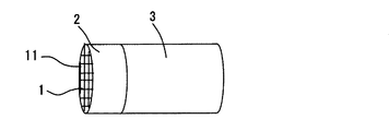
本例の排ガス浄化用触媒は、図1に示すように、排ガスが流通するガス流路10を形成する流路壁15の上流側に形成された上流側触媒層2と、流路壁15の上流側触媒層2よりも下流側に形成された下流側触媒層3とをもつ。流路壁15は、ガス流路10を有する構造を備えたハニカム基材1から構成されている。図2に示すように、ハニカム基材1は、長さ(L1)105mm、直径103mmの円筒体であり、コーディエライト製である。図3に示すように、ハニカム基材1には、長手方向に延びる多数の六角形断面のセル11が、流通壁15を構成する隔壁で区画されている。各セル11を囲む流通壁15の表面には、上流側触媒層2及び下流側触媒層3が形成されており、その表面の空間部にガス流路10が形成されている。
Example 1
As shown in FIG. 1, the exhaust gas purifying catalyst of this example includes an
図1に示すように、上流側触媒層2は、Pdと、Al2O3−ZrO2−CeO2−Pr6O11複合酸化物と、PdのHC被毒抑制用のBaとからなる。
As shown in FIG. 1, the upstream-
下流側触媒層3は、ハニカム基材1の流通壁15の表面に形成された内触媒層31と、内触媒層31の表面に形成された外触媒層32とからなる。内触媒層31は、Ptと、ZrO2−CeO2−La2O3−Y2O3複合酸化物とからなる。外触媒層32は、Rhと、Al2O3−ZrO2−CeO2−La2O3複合酸化物とからなる。
The
上流側触媒層2の長さ(L2)は30mm、下流側触媒層3の長さ(L3)は75mmであり、上流側触媒層2の長さと下流側触媒層3の長さとを合わせた合計長さ(L1=L2+L3)の下流側触媒層3の長さに対する比(L3/L1)は71.5%である。
The length (L2) of the
上流側触媒層2の厚みT1は、5μmである。下流側触媒層3の内触媒層31の厚みT2は、35μmであり、下流側触媒層3の外触媒層32の厚みT3は60μmであって、内触媒層の厚みに対する外触媒層の厚みの比率(T3/T2)は1.7である。
The
下流側触媒層3の全体厚み(T2+T3)は95μmである。上流側触媒層2の厚みの下流側触媒層の全体厚みに対する比率(T1/(T2+T3))は0.05である。
The overall thickness (T2 + T3) of the
次に、本例の排ガス浄化用触媒の製造方法について説明する。 Next, a method for producing the exhaust gas purifying catalyst of this example will be described.
まず、上流側触媒層の形成について説明する。Al、Zr、Ce、Prの各硝酸塩を純水に溶解して、5質量%の金属水溶液を調製する。次に、この金属水溶液を、金属水溶液に対して6倍質量の25質量%のアンモニア水溶液中に、60分で投入する。その後、室温で20分間撹拌し、濾過、洗浄により、水酸化物を得る。得られた水酸化物を800℃で5時間焼成して、Pd用担体であるAl2O3−ZrO2−CeO2−Pr6O11複合酸化物が得られる。この複合酸化物の組成は、Al2O3/ZrO2/CeO2/Pr6O11=50/22/24/4(質量%)である。なお、本担体には、ZrO2−CeO2の構造安定化剤として、La、Nd、Yなどの希土類元素を添加してもよい。
First, formation of the upstream catalyst layer will be described. Each nitrate of Al, Zr, Ce, and Pr is dissolved in pure water to prepare a 5% by mass metal aqueous solution. Next, this metal aqueous solution is thrown into a 25 mass% aqueous ammonia solution that is 6 times the mass of the metal aqueous solution in 60 minutes. Thereafter, the mixture is stirred at room temperature for 20 minutes, and a hydroxide is obtained by filtration and washing. The resulting hydroxide was fired for 5 hours at 800 ° C. The, Al 2 O 3 -ZrO 2 -CeO 2 -Pr 6
次に、蒸留水中に、上記Pd用担体を48g/L、硝酸Pd薬液(Pd:4.7質量%)4.0g/L、及びバインダとしてのアルミナゾル(Al2O3:10質量%)8.0g/Lを添加し、10分間攪拌する。次に、PdのHC被毒緩和用としてのBaSO4を12g/L添加して、上流側触媒層形成用のスラリーを調製する。 Next, in distilled water, the above Pd carrier was 48 g / L, Pd nitrate chemical (Pd: 4.7% by mass) 4.0 g / L, and alumina sol as a binder (Al 2 O 3 : 10% by mass) 8 Add 0.0 g / L and stir for 10 minutes. Next, 12 g / L of BaSO 4 for reducing HC poisoning of Pd is added to prepare a slurry for forming the upstream catalyst layer.
得られたスラリーをボールミルにて粒度調整し、ハニカム基材1に上流側端部1aから下流側へ30mmの部分までウォッシュコートして、上流側触媒層2とする。上流側触媒層2は、ハニカム基材1リットル当たり150g形成され、Pdはハニカム基材1リットル当たり3.5g担持する。
The particle size of the obtained slurry is adjusted by a ball mill, and the
次に、下流側触媒層の内触媒層の形成について説明する。Zr、Ce、La、Yの各硝酸塩を純水に溶解して5質量%の金属水溶液を調製する。この金属水溶液を、金属水溶液に対して6倍質量の25質量%のアンモニア水溶液中に60分で投入する。その後、室温で20分撹拌して、ろ過、洗浄により、水酸化物を得る。得られた水酸化物を800℃、5時間焼成し、Pt用担体であるZrO2−CeO2−La2O3−Y2O3複合酸化物が得られる。この複合酸化物の組成は、ZrO2/CeO2/La2O3/Y2O3=60/30/5/5(質量%)である。なお、本担体には、ZrO2−CeO2の構造安定化剤として、La、Nd、Yなどの希土類元素を添加してもよい。 Next, formation of the inner catalyst layer of the downstream catalyst layer will be described. Zr, Ce, La, and Y nitrates are dissolved in pure water to prepare a 5 mass% aqueous metal solution. This aqueous metal solution is poured into an aqueous ammonia solution of 25 mass%, 6 times the mass of the aqueous metal solution, in 60 minutes. Thereafter, the mixture is stirred at room temperature for 20 minutes, and a hydroxide is obtained by filtration and washing. The obtained hydroxide is fired at 800 ° C. for 5 hours to obtain a ZrO 2 —CeO 2 —La 2 O 3 —Y 2 O 3 composite oxide which is a Pt support. The composition of this composite oxide is ZrO 2 / CeO 2 / La 2 O 3 / Y 2 O 3 = 60/30/5/5 (mass%). Incidentally, the present carrier, as a structural stabilizer ZrO 2 -CeO 2, La, Nd , may be doped with a rare earth element such as Y.
次に、蒸留水中に、上記Pt用担体を96g/L、ジニトロジアミンPt薬液(Pt:4.4質量%)1.0g/L、及びバインダとしてのアルミナゾル(Al2O3:10質量%)3.0g/Lを添加し、10分間攪拌して、下流側の内触媒層用のスラリーとする。 Next, 96 g / L of the Pt carrier in distilled water, 1.0 g / L of dinitrodiamine Pt chemical solution (Pt: 4.4% by mass), and alumina sol as a binder (Al 2 O 3 : 10% by mass) Add 3.0 g / L and stir for 10 minutes to obtain a slurry for the inner catalyst layer on the downstream side.
得られたスラリーをボールミルにて粒度調整し、下流側端部1bから上流側へ75mmの部分までウォッシュコートして、下流側の内触媒層31を形成する。内触媒層31は、ハニカム基材1リットル当たり155g形成され、Ptはハニカム基材1リットル当たり0.6g担持し、ZrO2−CeO2−La2O3−Y2O3複合酸化物はハニカム基材1リットル当たり115g含ませる。
The particle size of the obtained slurry is adjusted with a ball mill, and the
次に、下流側触媒層の外触媒層の形成について説明する。Al、Zr、Ce、Laの各硝酸塩を純水に溶解して5質量%の金属水溶液を調製する。この金属水溶液を、金属水溶液に対して6倍質量の25質量%のアンモニア水溶液中に60分で投入する。その後、室温で20分撹拌して、ろ過、洗浄により、水酸化物を得る。得られた水酸化物を800℃、5時間焼成し、Pt用担体であるAl2O3−ZrO2−CeO2−La2O3複合酸化物が得られる。この複合酸化物の組成は、Al2O3/ZrO2/CeO2/La2O3=52/26/20/2(質量%)である。なお、本担体には、ZrO2−CeO2の構造安定化剤として、Nd、Yなどの希土類元素を添加してもよい。
Next, formation of the outer catalyst layer of the downstream catalyst layer will be described. Each nitrate of Al, Zr, Ce, and La is dissolved in pure water to prepare a 5% by mass metal aqueous solution. This aqueous metal solution is poured into an aqueous ammonia solution of 25 mass%, 6 times the mass of the aqueous metal solution, in 60 minutes. Thereafter, the mixture is stirred at room temperature for 20 minutes, and a hydroxide is obtained by filtration and washing. Obtained hydroxide to 800 ° C., and calcined 5 hours, Al 2 O 3 -ZrO 2 -CeO 2 -La 2
次に、蒸留水中に、上記Rh用担体を96g/L、硝酸Rh薬液(Rh:2.5質量%)0.2g/L、及びバインダとしてのアルミナゾル(Al2O3:10質量%)5.0g/Lを添加し、10分間攪拌する。 Next, in distilled water, 96 g / L of the Rh carrier, 0.2 g / L of nitric acid Rh nitrate solution (Rh: 2.5% by mass), and alumina sol (Al 2 O 3 : 10% by mass) as a binder 5 Add 0.0 g / L and stir for 10 minutes.
得られたスラリーをボールミルにて粒度調整し、下流側の内触媒層31の表面にウォッシュコートして、下流側の外触媒層32を形成する。外触媒層32は、ハニカム基材1リットル当たり150g形成され、Rhはハニカム基材1リットル当たり0.2g担持させる。
The particle size of the obtained slurry is adjusted by a ball mill, and the surface of the
(比較例1)
本例は、下流側触媒層3の内触媒層31の厚み(T2)が50μmであり、外触媒層32の厚み(T3)が30μmであって、内触媒層31の厚みに対する外触媒層32の厚みの比率(T3/T2)が0.6である。内触媒層31及び外触媒層32の貴金属担持量は、それぞれ、内触媒層31が131g/L、外触媒層32が61g/Lであり、その他は実施例1と同様である。
(Comparative Example 1)
In this example, the thickness (T2) of the
(比較例2)
本例は、下流側触媒層3の内触媒層31の厚み(T2)が40μmであり、外触媒層32の厚み(T3)が40μmであって、内触媒層31の厚みに対する外触媒層32の厚みの比率(T3/T2)が1.0である。内触媒層31及び外触媒層32の貴金属担持量は、それぞれ、内触媒層31が96g/L、外触媒層32が80g/Lであり、その他は実施例1と同様である。
(Comparative Example 2)
In this example, the thickness (T2) of the
(比較例3)
本例は、下流側触媒層3の内触媒層31の厚み(T2)が25μmであり、外触媒層32の厚み(T3)が90μmであって、内触媒層31の厚みに対する外触媒層32の厚みの比率(T3/T2)が3.6である。内触媒層31及び外触媒層32の貴金属担持量は、それぞれ、内触媒層31が61g/L、外触媒層32が131g/Lであり、その他は実施例1と同様である。
(Comparative Example 3)
In this example, the thickness (T2) of the
(耐久試験)
前記実施例1及び比較例1〜3の触媒をV型6気筒4.3リットルエンジンの排気系にそれぞれ装着し、ガソリンを用いて、入りガス温度1000℃、A/F(空燃比)14.6を中心に、A/F=14.0と、A/F=15.0との間を1Hzで振動させる条件で、50時間耐久試験を行った。
(An endurance test)
The catalysts of Example 1 and Comparative Examples 1 to 3 were respectively mounted on the exhaust system of a V-6 cylinder 4.3 liter engine, and gasoline was used to enter an input gas temperature of 1000 ° C. and A / F (air-fuel ratio) 14. A 50-hour endurance test was conducted under the condition of vibrating at 1 Hz between A / F = 14.0 and A / F = 15.0, centering on 6.
(HC50%浄化時間の測定)
前記耐久試験後に室温まで温度を低下させた各触媒を、直列排気量2.4Lのエンジンの排気系にそれぞれ装着した。入りガス温度450℃のストイキ雰囲気(A/F=14.2)の排ガスを各触媒に流通させ、排ガス流通直後からHC浄化率を連続的に測定した。そして、HC浄化率が50%に到達できる時間(HC50%浄化時間)を算出した。
(Measurement of HC50% purification time)
Each catalyst whose temperature was lowered to room temperature after the endurance test was installed in an exhaust system of an engine having a series displacement of 2.4 L. Exhaust gas in a stoichiometric atmosphere (A / F = 14.2) with an inlet gas temperature of 450 ° C. was passed through each catalyst, and the HC purification rate was continuously measured immediately after the exhaust gas flow. Then, a time during which the HC purification rate can reach 50% (HC 50% purification time) was calculated.
(CO−NOxクロス浄化率の測定)
前記耐久試験後の各触媒を、直列排気量2.4Lのエンジンの排気系にそれぞれ搭載し、触媒の入りガスと出ガスとを測定できるように排ガス成分分析計を設置した。エンジンの燃焼条件を変化させて、各触媒に流通させる排ガスの空燃比(A/F)を13.5から15.5まで変化させた。排ガスの触媒入りガス温度は、400℃と一定にした。この間の触媒から排出される各排ガス成分(CO、HC、NOx)の各濃度を測定した。触媒から排出される各排ガス成分の濃度を、触媒入りガスの排ガス成分の濃度で除して、CO、HC、NOxの浄化率を求めた。そして、CO浄化曲線とNOx浄化曲線とが交差する点の浄化率を「CO−NOxクロス浄化率」とした。
(Measurement of CO-NOx cross purification rate)
Each catalyst after the endurance test was mounted in an exhaust system of an engine with a series displacement of 2.4 L, and an exhaust gas component analyzer was installed so that the gas entering and leaving the catalyst could be measured. By changing the combustion conditions of the engine, the air-fuel ratio (A / F) of the exhaust gas flowing through each catalyst was changed from 13.5 to 15.5. The catalyst gas temperature of the exhaust gas was kept constant at 400 ° C. During this time, each concentration of each exhaust gas component (CO, HC, NOx) discharged from the catalyst was measured. The concentration of each exhaust gas component discharged from the catalyst was divided by the concentration of the exhaust gas component of the catalyst-containing gas to obtain the purification rate of CO, HC, and NOx. The purification rate at the point where the CO purification curve and the NOx purification curve cross each other was defined as “CO-NOx cross purification rate”.
(評価)
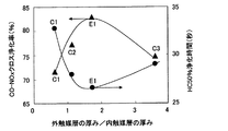
実施例1及び比較例1〜3の触媒についての前記クロス浄化率及びHC50%浄化時間を図6に示した。図6のX軸上に、内触媒層の厚みに対する外触媒層の厚みの比率(T3/T2)の低い触媒から順に配列させた。図6において、実施例1、比較例1,2,3の結果は、順に、E1、C1、C2、C3で示した。各触媒のクロス浄化率及びHC50%浄化時間を示す点を曲線で結ぶことにより、クロス浄化率曲線及びHC50%浄化時間曲線を作成した。
(Evaluation)
The cross purification rate and HC 50% purification time for the catalysts of Example 1 and Comparative Examples 1 to 3 are shown in FIG. On the X-axis of FIG. 6, the catalysts having the lower ratio of the thickness of the outer catalyst layer to the thickness of the inner catalyst layer (T3 / T2) were arranged in order. In FIG. 6, the results of Example 1 and Comparative Examples 1, 2, and 3 are shown as E1, C1, C2, and C3 in this order. A cross purification rate curve and an HC 50% purification time curve were created by connecting the points indicating the cross purification rate and the HC 50% purification time of each catalyst with a curve.
なお、HC−NOxクロス浄化率についても作成したところ、前記CO−NOxクロス浄化率と同様の結果が得られた。 In addition, when it created also about the HC-NOx cross purification rate, the result similar to the said CO-NOx cross purification rate was obtained.
図6より知られるように、実施例1の触媒は、比較例1〜3の触媒に比べて、クロス浄化率が高く、HC50%浄化時間も短かった。 As can be seen from FIG. 6, the catalyst of Example 1 had a higher cross purification rate and shorter HC 50% purification time than the catalysts of Comparative Examples 1 to 3.
図6に示されるクロス浄化率曲線及びHC50%浄化時間曲線から、内触媒層の厚みに対する外触媒層の厚みの比率(T3/T2)が1.5〜2.5の場合には、前記比率(T3/T2)が1の場合に比べて、クロス浄化率が高く、且つHC50%浄化時間も短くなることが分かった。更に、前記比率(T3/T2)が1.5〜2.2の場合には、クロス浄化率が更に高く、且つHC50%浄化時間も更に短くなることが分かった。よって、前記比率(T3/T2)が1.5〜2.5の場合、望ましくは1.5〜2.2の場合には、暖機時のクロス浄化率が高く、CO、HC及びNOx浄化性能に優れ、かつ、コールドスタード時に発生する炭化水素(HC)の浄化率を短時間で高めることができ、コールドスタート時のHC浄化性能に優れることがわかる。 From the cross purification rate curve and HC 50% purification time curve shown in FIG. 6, when the ratio of the thickness of the outer catalyst layer to the thickness of the inner catalyst layer (T3 / T2) is 1.5 to 2.5, the ratio As compared with the case where (T3 / T2) is 1, it was found that the cross purification rate is high and the HC 50% purification time is also shortened. Further, it was found that when the ratio (T3 / T2) is 1.5 to 2.2, the cross purification rate is further higher and the HC 50% purification time is further shortened. Therefore, when the ratio (T3 / T2) is 1.5 to 2.5, preferably 1.5 to 2.2, the cross purification rate during warm-up is high, and CO, HC and NOx purification are performed. It can be seen that the performance is excellent and the purification rate of hydrocarbon (HC) generated during cold start can be increased in a short time, and the HC purification performance at cold start is excellent.
一方、比較例2の触媒は、実施例1の触媒に比べて、クロス浄化率が低く、HC50%浄化時間も長かった。比較例3の触媒は、比較例2の触媒よりもさらにクロス浄化率が低く、HC50%浄化時間もさらに長かった。これは、外触媒層32の厚みが内触媒層31の厚みに比べて薄すぎて、外触媒層32に担持されているRhによるNOx浄化活性が低下し、また内触媒層31が厚すぎて内触媒層31の流通壁15に近い部分の温度上昇が遅れて、流通壁15に近い部分に担持されているPtによるCO浄化活性が低下したためであると考えられる。
On the other hand, the catalyst of Comparative Example 2 had a lower cross purification rate and longer HC50% purification time than the catalyst of Example 1. The catalyst of Comparative Example 3 had a lower cross purification rate than the catalyst of Comparative Example 2, and the HC 50% purification time was even longer. This is because the thickness of the
比較例3の触媒が、実施例1の触媒よりも、クロス浄化率が低く、HC50%浄化時間が長くなったのは、比較例3の外触媒層32が厚すぎて、内触媒31へのガス拡散距離が長くなり、低温時及び高温時ともに排ガス成分が内触媒層31に拡散しにくくなったこと、内触媒層31が薄すぎて内触媒層31に含まれているCeO2の含有量が少なく、酸素吸放出能が悪化したためであると考えられる。
The cross purification rate of the catalyst of Comparative Example 3 was lower than that of the catalyst of Example 1, and the HC50% purification time was longer because the
1:ハニカム基材、2:上流側触媒層、3:下流側触媒層、10:ガス流路、11:セル、15:流通壁、31:内触媒層、32:外触媒層。 1: honeycomb substrate, 2: upstream catalyst layer, 3: downstream catalyst layer, 10: gas flow path, 11: cell, 15: flow wall, 31: inner catalyst layer, 32: outer catalyst layer.
Claims (3)
前記上流側触媒層は、前記下流側触媒層よりも厚みが薄く、Pdを含み、
前記下流側触媒層は、前記流路壁の表面に形成されPt及びZrO2−CeO2複合酸化物を含む内触媒層と、前記内触媒層の表面に形成されRhを含む外触媒層とからなり、
前記内触媒層の厚みに対する前記外触媒層の厚みの比率は1.5〜2.5であることを特徴とする排ガス浄化用触媒。 An upstream catalyst layer formed on the upstream side of a flow path wall that forms a gas flow path through which exhaust gas flows, and a downstream catalyst layer formed on the downstream side of the upstream catalyst layer of the flow path wall; An exhaust gas purifying catalyst having
The upstream catalyst layer is thinner than the downstream catalyst layer and includes Pd,
The downstream catalyst layer includes an inner catalyst layer including Pt and ZrO 2 —CeO 2 composite oxide formed on the surface of the flow path wall, and an outer catalyst layer including Rh formed on the surface of the inner catalyst layer. Become
The ratio of the thickness of the outer catalyst layer to the thickness of the inner catalyst layer is 1.5 to 2.5.
Priority Applications (1)
| Application Number | Priority Date | Filing Date | Title |
|---|---|---|---|
| JP2008170859A JP5114317B2 (en) | 2008-06-30 | 2008-06-30 | Exhaust gas purification catalyst |
Applications Claiming Priority (1)
| Application Number | Priority Date | Filing Date | Title |
|---|---|---|---|
| JP2008170859A JP5114317B2 (en) | 2008-06-30 | 2008-06-30 | Exhaust gas purification catalyst |
Publications (2)
| Publication Number | Publication Date |
|---|---|
| JP2010005592A true JP2010005592A (en) | 2010-01-14 |
| JP5114317B2 JP5114317B2 (en) | 2013-01-09 |
Family
ID=41586666
Family Applications (1)
| Application Number | Title | Priority Date | Filing Date |
|---|---|---|---|
| JP2008170859A Active JP5114317B2 (en) | 2008-06-30 | 2008-06-30 | Exhaust gas purification catalyst |
Country Status (1)
| Country | Link |
|---|---|
| JP (1) | JP5114317B2 (en) |
Cited By (7)
| Publication number | Priority date | Publication date | Assignee | Title |
|---|---|---|---|---|
| JP2012040547A (en) * | 2010-07-23 | 2012-03-01 | Toyota Motor Corp | Exhaust gas purifying catalyst |
| WO2012101505A1 (en) | 2011-01-27 | 2012-08-02 | Toyota Jidosha Kabushiki Kaisha | Double layered exhaust gas purification catalyst |
| JP2013119075A (en) * | 2011-12-08 | 2013-06-17 | Toyota Motor Corp | Exhaust gas purifying catalyst |
| US8603940B2 (en) | 2010-11-05 | 2013-12-10 | Toyota Jidosha Kabushiki Kaisha | Automobile exhaust gas catalytic converter |
| US9233357B2 (en) | 2011-09-20 | 2016-01-12 | Nissan Motor Co., Ltd. | Exhaust gas purifying catalyst and method for producing same |
| JP2016131968A (en) * | 2015-01-22 | 2016-07-25 | 株式会社キャタラー | Catalyst for cleaning exhaust gas |
| WO2020241248A1 (en) | 2019-05-31 | 2020-12-03 | 三井金属鉱業株式会社 | Exhaust gas purification catalyst and exhaust gas purification system using said exhaust gas purification catalyst |
Citations (3)
| Publication number | Priority date | Publication date | Assignee | Title |
|---|---|---|---|---|
| JPH05293376A (en) * | 1992-04-15 | 1993-11-09 | Nissan Motor Co Ltd | Catalyst for purifying exhaust gas and method therefor |
| JP2003053151A (en) * | 2001-08-16 | 2003-02-25 | Valtion Teknillinen Tutkimuskeskus | Method for subjecting nitrogen oxide to catalytic reduction and catalyst therefor |
| WO2006057067A1 (en) * | 2004-11-25 | 2006-06-01 | Cataler Corporation | Catalyst for exhaust gas purification |
-
2008
- 2008-06-30 JP JP2008170859A patent/JP5114317B2/en active Active
Patent Citations (3)
| Publication number | Priority date | Publication date | Assignee | Title |
|---|---|---|---|---|
| JPH05293376A (en) * | 1992-04-15 | 1993-11-09 | Nissan Motor Co Ltd | Catalyst for purifying exhaust gas and method therefor |
| JP2003053151A (en) * | 2001-08-16 | 2003-02-25 | Valtion Teknillinen Tutkimuskeskus | Method for subjecting nitrogen oxide to catalytic reduction and catalyst therefor |
| WO2006057067A1 (en) * | 2004-11-25 | 2006-06-01 | Cataler Corporation | Catalyst for exhaust gas purification |
Cited By (10)
| Publication number | Priority date | Publication date | Assignee | Title |
|---|---|---|---|---|
| JP2012040547A (en) * | 2010-07-23 | 2012-03-01 | Toyota Motor Corp | Exhaust gas purifying catalyst |
| US8603940B2 (en) | 2010-11-05 | 2013-12-10 | Toyota Jidosha Kabushiki Kaisha | Automobile exhaust gas catalytic converter |
| WO2012101505A1 (en) | 2011-01-27 | 2012-08-02 | Toyota Jidosha Kabushiki Kaisha | Double layered exhaust gas purification catalyst |
| US8853120B2 (en) | 2011-01-27 | 2014-10-07 | Toyota Jidosha Kabushiki Kaisha | Double layered exhaust gas purification catalyst |
| US9233357B2 (en) | 2011-09-20 | 2016-01-12 | Nissan Motor Co., Ltd. | Exhaust gas purifying catalyst and method for producing same |
| JP2013119075A (en) * | 2011-12-08 | 2013-06-17 | Toyota Motor Corp | Exhaust gas purifying catalyst |
| JP2016131968A (en) * | 2015-01-22 | 2016-07-25 | 株式会社キャタラー | Catalyst for cleaning exhaust gas |
| WO2016117393A1 (en) * | 2015-01-22 | 2016-07-28 | 株式会社キャタラー | Catalyst for purifying exhaust gas |
| US10369520B2 (en) | 2015-01-22 | 2019-08-06 | Cataler Corporation | Exhaust gas cleaning catalyst |
| WO2020241248A1 (en) | 2019-05-31 | 2020-12-03 | 三井金属鉱業株式会社 | Exhaust gas purification catalyst and exhaust gas purification system using said exhaust gas purification catalyst |
Also Published As
| Publication number | Publication date |
|---|---|
| JP5114317B2 (en) | 2013-01-09 |
Similar Documents
| Publication | Publication Date | Title |
|---|---|---|
| JP6010205B2 (en) | Exhaust gas purification catalyst | |
| JP4760625B2 (en) | Exhaust gas purification catalyst device | |
| US10010873B2 (en) | Catalytic converter | |
| JP5996538B2 (en) | Catalyst for lean-burn gasoline engines with improved NO oxidation activity | |
| JP6864677B2 (en) | Exhaust gas purification catalyst | |
| US8067330B2 (en) | Catalytic material and catalyst for purifying exhaust gas component | |
| JP2010005590A (en) | Catalyst for purifying exhaust gas | |
| JP5114317B2 (en) | Exhaust gas purification catalyst | |
| WO2007010899A1 (en) | Exhaust gas purifying catalyst | |
| JP5804004B2 (en) | Catalytic converter | |
| JP2010029752A (en) | Catalyst device for purifying exhaust gas and exhaust gas purifying method | |
| JP5065180B2 (en) | Exhaust gas purification catalyst | |
| JP2009273988A (en) | Catalyst for cleaning exhaust gas | |
| WO2008010576A1 (en) | Catalyst for exhaust gas purification | |
| JP5218092B2 (en) | Exhaust gas purification catalyst | |
| KR20130101525A (en) | Catalyst for gasoline lean burn engines with improved nh3-formation activity | |
| CN107081065B (en) | Exhaust gas purification catalyst device, exhaust gas purification system, and method for detecting deterioration of exhaust gas purification catalyst device | |
| JP2008114153A (en) | Catalyst for purification of exhaust gas and system and method for purification of exhaust gas | |
| JP2008296090A (en) | Exhaust cleaning catalyst, exhaust cleaning system, and exhaust cleaning method | |
| WO2018199250A1 (en) | Exhaust gas purification catalyst and exhaust gas purification method using same | |
| JP2008284487A (en) | Sulfur occlusion catalyst and apparatus for cleaning exhaust gas | |
| JP4413366B2 (en) | Exhaust gas purification catalyst | |
| JP5232258B2 (en) | Exhaust gas purification device for internal combustion engine | |
| JP5078638B2 (en) | Exhaust gas purification device | |
| JP5328133B2 (en) | Exhaust gas purification catalyst |
Legal Events
| Date | Code | Title | Description |
|---|---|---|---|
| A621 | Written request for application examination |
Free format text: JAPANESE INTERMEDIATE CODE: A621 Effective date: 20110609 |
|
| A977 | Report on retrieval |
Free format text: JAPANESE INTERMEDIATE CODE: A971007 Effective date: 20120918 |
|
| TRDD | Decision of grant or rejection written | ||
| A01 | Written decision to grant a patent or to grant a registration (utility model) |
Free format text: JAPANESE INTERMEDIATE CODE: A01 Effective date: 20120925 |
|
| A01 | Written decision to grant a patent or to grant a registration (utility model) |
Free format text: JAPANESE INTERMEDIATE CODE: A01 |
|
| A61 | First payment of annual fees (during grant procedure) |
Free format text: JAPANESE INTERMEDIATE CODE: A61 Effective date: 20121015 |
|
| FPAY | Renewal fee payment (event date is renewal date of database) |
Free format text: PAYMENT UNTIL: 20151019 Year of fee payment: 3 |
|
| R151 | Written notification of patent or utility model registration |
Ref document number: 5114317 Country of ref document: JP Free format text: JAPANESE INTERMEDIATE CODE: R151 |
|
| FPAY | Renewal fee payment (event date is renewal date of database) |
Free format text: PAYMENT UNTIL: 20151019 Year of fee payment: 3 |
|
| R250 | Receipt of annual fees |
Free format text: JAPANESE INTERMEDIATE CODE: R250 |
|
| R250 | Receipt of annual fees |
Free format text: JAPANESE INTERMEDIATE CODE: R250 |
|
| R250 | Receipt of annual fees |
Free format text: JAPANESE INTERMEDIATE CODE: R250 |
|
| R250 | Receipt of annual fees |
Free format text: JAPANESE INTERMEDIATE CODE: R250 |
|
| R250 | Receipt of annual fees |
Free format text: JAPANESE INTERMEDIATE CODE: R250 |
|
| R250 | Receipt of annual fees |
Free format text: JAPANESE INTERMEDIATE CODE: R250 |
|
| R250 | Receipt of annual fees |
Free format text: JAPANESE INTERMEDIATE CODE: R250 |
|
| R250 | Receipt of annual fees |
Free format text: JAPANESE INTERMEDIATE CODE: R250 |