JP2010004646A - Superconducting rotating machine - Google Patents
Superconducting rotating machine Download PDFInfo
- Publication number
- JP2010004646A JP2010004646A JP2008160706A JP2008160706A JP2010004646A JP 2010004646 A JP2010004646 A JP 2010004646A JP 2008160706 A JP2008160706 A JP 2008160706A JP 2008160706 A JP2008160706 A JP 2008160706A JP 2010004646 A JP2010004646 A JP 2010004646A
- Authority
- JP
- Japan
- Prior art keywords
- superconducting
- inner tank
- tank
- superconducting coil
- cooling medium
- Prior art date
- Legal status (The legal status is an assumption and is not a legal conclusion. Google has not performed a legal analysis and makes no representation as to the accuracy of the status listed.)
- Granted
Links
Images


Abstract
Description
本発明は、船舶、鉄道、陸上車輌、航空機等に使用される、超電導モータ、発電機等の一部を構成する超電導コイルがFRP製クライオスタット内に収納されている超電導(超伝導といわれることもある。)回転機器に関するものである。 The present invention relates to superconductivity (also referred to as superconductivity) in which a superconducting coil that constitutes a part of a superconducting motor, generator, etc. used in ships, railways, land vehicles, aircraft, etc. is housed in a cryostat made of FRP. Yes.) It relates to rotating equipment.
近年、交流電源を用いる同期機で電機子コイルや界磁コイルとして、超電導コイルを用いた超電導モータが開発され、船舶や鉄道、陸上車輌、航空機等に適用する試みがなされている。このような超電導体を収納する、外槽と内槽からなり、該外槽と内槽間が真空断熱層とされたFRP製クライオスタットの成形法は特許文献1〜3等に開示されている。また、FRP製クライオスタットの壁部には、冷却媒体用配管と電流導入端子用の貫通継手を配設する必要があり、このような貫通継手等はクライオスタットに貫通する金属製部材を設け、該部材に貫通継手等を接合して固着されていたが、冷却と昇温時の熱応力等の各種応力により、真空断熱層の真空漏れを引き起こす箇所となっていた。
出願人らは、FRP製クライオスタットに金属製部材を固着し、該部材に貫通継手等を接合する場合に真空断熱層の真空漏れを防止する方法について検討を行い、その改良発明は、既に下記特許文献4に開示している。
In recent years, a superconducting motor using a superconducting coil as an armature coil or a field coil in a synchronous machine using an AC power source has been developed, and attempts have been made to apply it to ships, railways, land vehicles, airplanes and the like.
Applicants have studied a method for preventing vacuum leakage of a vacuum heat insulating layer when a metal member is fixed to an FRP cryostat and a penetration joint or the like is joined to the member. This is disclosed in Document 4.
通常、超電導モータの例として、例えば同期機において、(i)界磁に超電導コイル、電機子に常電導コイルを用いる場合、(ii)電機子に超電導コイル、界磁に永久磁石を用いる場合、(iii)電機子、界磁ともに超電導コイルを用いる場合等が考えられる。
出願人らは、先に出願した特許文献5で、電機子と界磁の両者に超電導コイルを用いた超電導モータにおいて、その内ケース(以下、内槽という。)内には、超電導コイルを冷却するための冷却媒体が充填されており、さらに外ケース(以下、外槽という。)と内槽との間の空間が真空断熱層とされ、前記超電導コイルを収納したケースの外槽内には、固定子と回転子とが対向する方向に沿って伸長されかつ内槽および超電導コイルの内周側を貫通する柱状体が配設されており、その柱状体の両端が外槽の内面に接して、その柱状体により外槽の内側への変形を防止する構成を提案した。このような構成とすることにより、真空断熱層の外側の壁、すなわち外槽の壁を薄くしても大気圧との差圧による外ケースの壁の変形を招かないようにし、これによって外槽の壁厚を薄くして回転子、固定子の磁極面間の距離を従来よりも小さくすることができ、その結果、超電導モータとしての回転出力(トルク)を増加させ得ることを可能にした。
Usually, as an example of a superconducting motor, for example, in a synchronous machine, (i) when a superconducting coil is used for the field, a normal conducting coil is used for the armature, (ii) when a superconducting coil is used for the armature, and a permanent magnet is used for the field, (Iii) The case where a superconducting coil is used for both the armature and the field is considered.
In the superconducting motor using the superconducting coil for both the armature and the field in
特許文献6には、回転子側に超電導コイルを取り付けた超電導モータの冷却構造として、回転子に貫通させて固定された回転軸の外面に溝が凹設され、冷却手段の冷媒流通管を前記溝内部に挿入配置していることを特徴とする超電導モータが開示されている。
特許文献7には、永久磁石を含む回転子と,電機子巻線を含む固定子とがアキシャル方向に対向する回転界磁型のアキシャルギャップ型モータとして、回転子の軸線方向に固定子を所要の空隙をあけて対向配置し、前記回転子と前記固定子のいずれか一方に複数の界磁体を軸線回りに配置していると共に、いずれか他方に複数の電機子コイルを軸線回りに配置し、前記界磁体と前記電機子コイルの少なくとも一方を超電導材で形成し、磁束方向を軸線方向に向けて配置していることを特徴とする超電導モータが開示されている。
In Patent Document 6, as a cooling structure of a superconducting motor having a superconducting coil attached to the rotor side, a groove is provided in the outer surface of a rotating shaft that is fixed by penetrating the rotor. A superconducting motor characterized by being inserted and disposed in the groove is disclosed.
船舶、鉄道、陸上車輌、航空機に使用される超電導モータ等の超電導回転機器の超電導コイルが収納されるクライオスタットの内槽は、通常その外形形状が円筒形状(具体例としては、蓮根を中心軸と垂直方向に切り取った形状)をした容器であり、該容器の胴部は曲面形状であるので、従来、全ての金属製貫通継手は超電導モータ等の回転軸が垂直方向の場合には、上部蓋部又は下部の底板部、又は該回転軸が水平方向の場合には円筒形状の平面部である左右側面部(以下、超電導モータ等の回転軸が垂直の場合の該上部蓋部又は下部の底板部と、該回転軸が水平の場合の該左右側面部を併せて「円筒形状の上部蓋部もしくは下部底板部又は平面部である側面部」という。)に配設され、外槽と内槽間の真空断熱層の真空漏れを防止して安定的な運転を可能としていた。
また、超電導回転機器の外槽胴部に金属製貫通継手が設けられている場合においても、外槽と内槽間の真空断熱層領域内において冷却媒体用配管及び電流導入コードを内槽外表面部近傍に沿わせて、内槽の円筒形状の上部蓋部もしくは下部底板部又は平面部である側面部に冷却媒体配管用貫通継手及び電流導入端子用貫通継手が配設されていた。
The inner tank of a cryostat that houses superconducting coils of superconducting rotating equipment such as superconducting motors used in ships, railways, land vehicles, and aircraft is usually cylindrical in shape (for example, the lotus root is the central axis). Since the body of the container has a curved surface, all metal penetration joints conventionally have a top cover when the rotation axis of a superconducting motor or the like is in the vertical direction. Left or right side surface that is a cylindrical flat surface when the rotation axis is horizontal (hereinafter, the upper lid or lower bottom plate when the rotation axis of a superconducting motor or the like is vertical) And the left and right side surfaces when the rotation axis is horizontal are collectively referred to as “cylindrical upper lid, lower bottom plate or flat side”, and the outer and inner tanks. Prevents vacuum leakage of the vacuum insulation layer between Was it possible to specific operation.
Even when a metal penetration joint is provided in the outer tank body of the superconducting rotating machine, the cooling medium pipe and the current introduction cord are connected to the outer surface of the inner tank in the vacuum heat insulating layer region between the outer tank and the inner tank. A cooling medium pipe penetration joint and a current introduction terminal penetration joint were arranged on the cylindrical upper lid portion or lower bottom plate portion of the inner tank or the side surface portion that is a flat portion along the vicinity of the portion.
例えば、特許文献6には、回転子に超電導コイルを取り付けた超電導モータの冷却構造であって、回転子に貫通させて固定された回転軸の外面に溝が凹設され、該溝に挿入した冷媒循環パイプに冷媒を流通させて、該冷媒により超電導コイルを冷却する、超電導モータの冷却構造が開示されている。また、特許文献7には、貫通継手が両側面に配設された構造が開示されている。
上記特許文献6、7のいずれにおいても金属製貫通継手を内槽の胴部に配設することは開示されていない。
For example, Patent Document 6 discloses a cooling structure for a superconducting motor in which a superconducting coil is attached to a rotor, and a groove is formed in the outer surface of a rotating shaft that is fixed through the rotor and inserted into the groove. A cooling structure for a superconducting motor is disclosed in which a refrigerant is circulated through a refrigerant circulation pipe and a superconducting coil is cooled by the refrigerant.
Neither of the above-mentioned
ところで超電導モータに限らず一般にモータにおいては、充分な回転出力を発生させるためには、相互に対向する回転子側の磁極面と固定子側の磁極面との間の間隔(該間隔は、内槽と外槽の壁厚、真空断熱層、及び空隙よりなる)を可及的に小さくすることが望ましい。
また、従来技術において金属製貫通継手は、上述したように「円筒形状の上部蓋部もしくは下部底板部又は平面部である側面部」のFRP製平板部に設けられていたが、特に貫通継手を「円筒形状の上部蓋部もしくは下部底板部又は平面部である側面部」のいずれかの一箇所に集めることにより、他方の真空断熱槽の厚みを極小化する構造が考慮されていた。
特許文献5には、回転子側の磁極面と固定子側の磁極面との間の間隔を小さくするために、内槽と外槽の壁厚を小さくし、それにより剛性が低下して外槽が内槽側に変形して、内槽の外面に接触して断熱効果が損なわれるのを防止するために、超電導コイルを収納したケースの外槽(外ケース)内には、固定子と回転子とが対向する方向に沿って伸長されかつ内槽(内ケース)および超電導コイルの内周側を貫通する柱状体を配設することが開示されている。
By the way, not only a superconducting motor but generally a motor, in order to generate a sufficient rotational output, in order to generate a sufficient rotational output, an interval between the mutually opposing rotor side magnetic pole surface and stator side magnetic pole surface (the interval is an internal It is desirable to make the wall thickness of the tank and the outer tank, the vacuum heat insulating layer, and the gap as small as possible.
Further, in the prior art, the metal penetration joint is provided on the FRP flat plate portion of the “cylindrical upper lid portion or lower bottom plate portion or the side portion which is a flat portion” as described above. A structure that minimizes the thickness of the other vacuum heat insulating tank by collecting it in any one of the “cylindrical upper lid portion, lower bottom plate portion, or side portion that is a flat portion” has been considered.
In
しかし、貫通継手を配置している側では、これらの継手を介して冷却媒体流入、流出用配管や電流導入端子(電流リード線)が接続されているので、該側における、内槽壁と対向する外槽壁との間の真空断熱層に冷却媒体流入、流出用配管や電流導入端子が付設される結果、真空断熱層が大きな厚み(例えば50mm程度)となる問題が残されていた。例えば、特許文献5においては、柱状体は超電導コイルの内周側を貫通して外槽の両内面に接しているので磁束線を形成する柱状体内側に収納された鉄芯は、超電導コイルよりも軸線方向の長さがより長くなるという問題点があった。
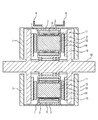
特許文献5に開示された上記構造を適用した超電導回転機の断面の概念図を図1に示す。図1に示すように、回転子を界磁として固定子を電機子とする同期機において、超電導コイルと鉄芯は十分に近接しているものの、鉄芯の長さは、円筒容器の回転子軸方向の真空断熱層の厚みが大きいことに起因して、固定子である超電導コイルの回転軸方向の幅に比べて長くなり、鉄芯の長さが長くなれば磁気抵抗が大きくなり、漏れ磁束が増えて回転出力の向上が図れないという問題点があった。
However, on the side where the through joints are arranged, the cooling medium inflow and outflow pipes and the current introduction terminals (current lead wires) are connected via these joints, so that they face the inner tank wall on that side. As a result of the cooling medium inflow and outflow piping and the current introduction terminal being attached to the vacuum heat insulating layer between the outer tank wall and the outer tank wall, there remains a problem that the vacuum heat insulating layer has a large thickness (for example, about 50 mm). For example, in
FIG. 1 shows a conceptual diagram of a cross section of a superconducting rotating machine to which the structure disclosed in
本発明は以上の事情を背景としてなされたもので、外槽と、全体として円筒形状の容器である内槽からなる内外2重壁構造槽の内槽の内側に電機子として超電導コイルが鉄芯の周りに収納されている、超電導回転機器において、該内槽の円筒形状の胴部に冷却媒体配管用貫通継手及び電流導入端子用貫通継手を配設することにより、内槽両側面の平板部とそれぞれ対向する外槽との間の真空断熱層の厚みを小さくして超電導コイルと永久磁石とを近接させると共に、回転子軸方向における鉄芯の長さを超電導コイルの軸方向の幅に近づけることが可能となり、その結果、磁路が有効に形成されて回転出力を向上できることを見出し、本発明を完成させた。 The present invention has been made against the background of the above circumstances, and a superconducting coil is an iron core as an armature inside an inner tub of an outer tub and an inner and outer double-walled tub composed of an inner tub that is a cylindrical container as a whole. In the superconducting rotating device housed around the flat plate portion on both sides of the inner tank, by disposing a through joint for cooling medium piping and a through joint for current introduction terminal in the cylindrical body of the inner tank And the superconducting coil and the permanent magnet are brought close to each other, and the length of the iron core in the rotor axial direction is made closer to the axial width of the superconducting coil. As a result, the inventors have found that the magnetic path can be effectively formed and the rotational output can be improved, and the present invention has been completed.
すなわち、本発明は、以下の(1)ないし(6)の記載を要旨とする発明である。
(1)磁極面側が相互に平行に空隙を隔てて対向する回転子と固定子のうち、少なくとも固定子側に電機子として超電導コイルが鉄芯の周りに配設されており、かつ該超電導コイルが外槽と、外形の全体形状が円筒形状の容器である内槽との内外2重壁構造槽の内槽内に収納されていて、該内槽内には超電導コイルを冷却するために外槽壁と内槽壁に配設された冷却媒体配管用貫通継手を介して循環される冷却媒体が収容されており、更に外槽と内槽との間の空間が真空断熱層とされた超電導回転機器であって、該内槽の胴部に冷却媒体配管用貫通継手及び電流導入端子用貫通継手が配設されていることを特徴とする超電導回転機器(以下、第1の態様ということがある)。
(2)前記内槽が繊維強化プラスチックにより成形された内槽であることを特徴とする前記(1)に記載の超電導回転機器(以下、第2の態様ということがある)。
(3)前記内槽の胴部の少なくとも一部に平面部を設けて、該平面部に冷却媒体配管用貫通継手及び電流導入端子用貫通継手を配設することを特徴とする前記(1)又は(2)に記載の超電導回転機器(以下、第3の態様ということがある)。
(4)前記内槽の胴部の少なくとも一部に設けられた平面部が、該内槽を成形する際に内槽の壁と一体的に成形された平面部であることを特徴とする前記(3)に記載の超電導回転機器(以下、第4の態様ということがある)。
(5)前記内槽の胴部の少なくとも一部に設けられた平面部が、FRP製の座を接着することにより設けられ平面部であることを特徴とする前記(3)に記載の超電導回転機器(以下、第5の態様ということがある)。
(6)前記超電導回転機器が回転子側に界磁として永久磁石が固定され、固定子側に電機子として超電導コイルが配設されているアキシャル型超電導モータであることを特徴とする前記(1)ないし(6)のいずれかに記載の超電導回転機器(以下、第6の態様ということがある)。
That is, the present invention is an invention having the gist of the following descriptions (1) to (6).
(1) A superconducting coil is disposed around an iron core as an armature on at least the stator side of a rotor and a stator whose magnetic pole face sides are opposed to each other in parallel with a gap, and the superconducting coil Is housed in an inner tank of an inner / outer double wall structure tank with an outer tank and an inner tank whose outer shape is a cylindrical container, and the outer tank is used for cooling the superconducting coil. A superconducting material that contains a cooling medium that is circulated through a through hole for cooling medium piping disposed on the tank wall and the inner tank wall, and in which the space between the outer tank and the inner tank is a vacuum heat insulating layer. A superconducting rotary device (hereinafter referred to as a first mode), characterized in that a through-joint for cooling medium piping and a through-joint for current introduction terminal are disposed in a body portion of the inner tank. is there).
(2) The superconducting rotary device according to (1), wherein the inner tank is an inner tank formed of fiber-reinforced plastic (hereinafter, sometimes referred to as a second aspect).
(3) The above-mentioned (1), wherein a flat portion is provided on at least a part of the body portion of the inner tank, and a through joint for cooling medium piping and a through joint for current introduction terminal are disposed on the flat portion. Alternatively, the superconducting rotary device according to (2) (hereinafter sometimes referred to as a third aspect).
(4) The flat portion provided in at least a part of the body portion of the inner tub is a flat portion integrally formed with the wall of the inner tub when the inner tub is formed. (3) The superconducting rotating device (hereinafter, sometimes referred to as a fourth aspect).
(5) The superconducting rotation as described in (3) above, wherein the flat portion provided in at least a part of the body portion of the inner tank is a flat portion provided by bonding a seat made of FRP. Equipment (hereinafter sometimes referred to as fifth aspect).
(6) The superconducting rotating machine is an axial type superconducting motor in which a permanent magnet is fixed as a field magnet on the rotor side and a superconducting coil is disposed as an armature on the stator side. ) To the superconducting rotating device according to any one of (6) (hereinafter may be referred to as a sixth embodiment).
上記第1の態様に記載の「超電導回転機器」は、超電導コイルが収納されている内槽の胴部に冷却媒体配管用貫通継手及び電流導入端子用の貫通継手が配設されており、これまで「円筒形状の上部蓋部もしくは下部底板部又は平面部である側面部」に配設していた冷却媒体配管用貫通継手及び電流導入端子用の貫通継手を該円筒形状の上部蓋部もしくは下部底板部又は平面部である側面部に配設する必要がないので、該部(前記上部蓋部もしくは下部底板部、又は側面部)における内槽と外槽間の真空断熱層の厚みを小さくすることができ、それにより、超電導回転モータ等における該モータの電機子コイルである中空円筒形状の超電導コイル軸方向の幅(ドライブシャフトの回転軸方向の幅)に、界磁である両面の永久磁石間に配設されていて該超電導コイルの中空部内で磁路を形成する鉄芯長さを近づけることが可能になり、その結果、磁束漏れが抑制可能になり磁路がより有効に形成されて回転出力を更に向上することができる。 In the “superconducting rotating device” described in the first aspect, a through joint for cooling medium piping and a through joint for current introduction terminal are disposed on the body of the inner tank in which the superconducting coil is housed. Until the "cylindrical upper lid or lower bottom plate or side surface that is a flat surface", the cooling medium pipe penetration joint and the current introduction terminal penetration joint are connected to the cylindrical upper lid or lower part. Since it is not necessary to arrange in the side plate part which is a bottom plate part or a plane part, the thickness of the vacuum heat insulation layer between the inner tank and the outer tank in the part (the upper lid part or the lower bottom plate part or the side part) is reduced. Thus, in a superconducting rotary motor or the like, the hollow cylindrical superconducting coil axial width of the motor armature coil (width in the rotational axis direction of the drive shaft) has a double-sided permanent magnet as a field. Arranged between Thus, the length of the iron core forming the magnetic path in the hollow portion of the superconducting coil can be made closer, and as a result, magnetic flux leakage can be suppressed and the magnetic path is more effectively formed to further improve the rotational output. be able to.
上記第2の態様2に記載の「超電導回転機器」における内槽は、繊維強化プラスチックにより成形されているので、金属材料を使用した場合に生ずる磁性の変動に伴い、その内部に渦電流が発生して磁場に歪を生じる等の不都合を回避することができる。
上記第3の態様に記載の「超電導回転機器」は、超電導コイルが収納されている外形の形状が全体として円筒形状(具体的には、図3、4に示すように、蓮根を中心軸と垂直方向に切り取った形状である、以下、「外形が円筒形状」ということがある。)の内槽の胴部の少なくとも一部に平面部が設けられているので、該平面部に冷却媒体配管用貫通継手及び電流導入端子用の貫通継手を配設することにより、真空漏れを有効に防ぐことが可能となる。
上記第4の態様に記載の「超電導回転機器」における内槽の胴部の少なくとも一部に設けられた平面部は、該内槽を成形する際に内槽の胴部と一体的に形成された平面部であるので、該平面部を形成するための接続部、接着部分等を設ける必要がなく、真空漏れをより減少でき、熱応力等の各種応力の影響が減少されるのでより長期間の安定運転が可能となる。
Since the inner tank in the “superconducting rotating machine” according to the
In the “superconducting rotating device” described in the third aspect, the outer shape in which the superconducting coil is accommodated is generally cylindrical (specifically, as shown in FIGS. 3 and 4, the lotus root is the central axis. Since the flat part is provided in at least a part of the body part of the inner tub of the shape cut in the vertical direction (hereinafter referred to as “the outer shape may be a cylindrical shape”), the coolant pipe is provided in the flat part. By providing the through joint for use and the through joint for the current introduction terminal, it becomes possible to effectively prevent vacuum leakage.
The flat portion provided in at least a part of the inner tank body in the “superconducting rotating device” according to the fourth aspect is formed integrally with the inner tank body when the inner tank is formed. Therefore, it is not necessary to provide a connection part, an adhesive part, etc. for forming the flat part, vacuum leakage can be further reduced, and the influence of various stresses such as thermal stress can be reduced for a longer period of time. Stable operation becomes possible.
上記第5の態様に記載の「超電導回転機器」における内槽の胴部の少なくとも一部に設けられた平面部は、FRP製の座を接着することにより設けられる平面部であるので、該平面部の形成場所の選定が比較的容易で、かつ胴部曲面に平面部を断続的に、後加工で形成することができる。
上記第6の態様に記載の「超電導回転機器」は回転子側に界磁として永久磁石が固定され、固定子側に電機子として超電導コイルが配設されているアキシャル型超電導モータであるので、超電導回転モータ等における該モータの電機子コイルである中空円筒形状の超電導コイルの回転軸方向の幅に、界磁である両面の永久磁石間に配設されていて該超電導コイルの中空部内で磁路を形成する鉄芯長さを近づけることが可能になり、その結果磁路がより有効に形成されて回転出力を向上することが可能になる。
Since the plane part provided in at least a part of the trunk of the inner tank in the “superconducting rotating device” according to the fifth aspect is a plane part provided by adhering a seat made of FRP, the plane It is relatively easy to select the formation place of the part, and the flat part can be intermittently formed on the body curved surface by post-processing.
Since the “superconducting rotating device” described in the sixth aspect is an axial superconducting motor in which a permanent magnet is fixed as a field on the rotor side and a superconducting coil is disposed as an armature on the stator side, In a superconducting rotary motor or the like, the width of the hollow cylindrical superconducting coil, which is the armature coil of the motor, is arranged between the permanent magnets on both sides of the field, and is magnetized in the hollow portion of the superconducting coil. The length of the iron core forming the path can be reduced, and as a result, the magnetic path can be more effectively formed and the rotational output can be improved.
本発明の「超電導回転機器」は、磁極面側が相互に平行に空隙を隔てて対向する回転子と固定子のうち、少なくとも固定子側に電機子として超電導コイルが鉄芯の周りに配設されており、かつ該超電導コイルが外槽と、外形の全体形状が円筒形状の容器である内槽との内外2重壁構造槽の内槽内に収納されていて、該内槽内には超電導コイルを冷却するために外槽壁と内槽壁に配設された冷却媒体配管用貫通継手を介して循環される冷却媒体が収容されており、更に外槽と内槽との間の空間が真空断熱層とされた超電導回転機器であって、該内槽の胴部の少なくとも一部に平面部を設けて、該平面部に冷却媒体配管用貫通継手及び電流導入端子用貫通継手が配設されていることを特徴とする。 In the “superconducting rotating device” of the present invention, a superconducting coil is disposed around an iron core as an armature on at least the stator side of a rotor and a stator whose magnetic pole face sides are opposed to each other in parallel with a gap. And the superconducting coil is housed in an inner tub of an inner and outer double wall structure tub with an outer tub and an inner tub whose outer shape is a cylindrical container. In order to cool the coil, a cooling medium circulated through a cooling medium pipe penetration joint disposed on the outer tank wall and the inner tank wall is accommodated, and a space between the outer tank and the inner tank is further provided. A superconducting rotary device with a vacuum heat insulation layer, in which a flat portion is provided on at least a part of the trunk of the inner tank, and a through joint for cooling medium piping and a through joint for current introduction terminal are provided on the flat portion. It is characterized by being.
以下、本発明の超電導回転機器について説明する。
本発明の超電導回転機器は、磁極面側が相互に平行に空隙を隔てて対向する回転子と固定子のうち、少なくとも固定子側に電機子として超電導コイルが鉄芯の周りに配設されており、かつ該超電導コイルが外槽と、全体として円筒形状の容器である内槽との内外2重壁構造槽の内槽内に収納されていて、該内槽内には超電導コイルを冷却するために外槽壁と内槽壁に配設された冷却媒体配管用貫通継手を介して循環される冷却媒体が収容されており、更に外槽と内槽との間の空間が真空断熱層とされた超電導回転機器に適用が可能であり、超電導モータに限定されず、超電導発電機にも適用が可能である。
Hereinafter, the superconducting rotary device of the present invention will be described.
In the superconducting rotating device of the present invention, a superconducting coil is disposed around the iron core as an armature on at least the stator side of the rotor and the stator facing each other with a gap in parallel on the magnetic pole surface side. In addition, the superconducting coil is housed in an inner tank of an inner / outer double wall structure tank of an outer tank and an inner tank that is a cylindrical container as a whole, and the superconducting coil is cooled in the inner tank. The cooling medium circulated through the cooling medium pipe penetration joint disposed on the outer tank wall and the inner tank wall is housed, and the space between the outer tank and the inner tank is a vacuum heat insulating layer. The present invention can be applied to a superconducting rotating device, and is not limited to a superconducting motor, but can also be applied to a superconducting generator.
又、例えば、超電導モータにおいては、少なくとも固定子側に電機子として超電導コイルが鉄芯の周りに配設されており、かつ該超電導コイルが全体として円筒形状の容器である内槽内に収納されている構造であれば回転子側が永久磁石又は超電導コイルのいずれの場合でも適用が可能である。従来、回転子(界磁)を超電導コイルで製作し、固定子(電機子)を銅コイルで製作するのが一般的であったが、本発明の超電導回転機器では固定子(電機子)に超電導コイルを用い、回転子(界磁)に永久磁石を用いるアキシャル型にも適用することが可能である。以下に、本発明の超電導回転機器の一例として、図2〜5を用いて説明する。
尚、図2〜5は本発明の例示であり、本発明はこれらの図に示す超電導回転機器に何ら限定されるものではない。
For example, in a superconducting motor, a superconducting coil is disposed around an iron core as an armature at least on the stator side, and the superconducting coil is accommodated in an inner tank which is a cylindrical container as a whole. If the structure is such that the rotor side is a permanent magnet or a superconducting coil, the present invention can be applied. Conventionally, a rotor (field) is generally manufactured by a superconducting coil and a stator (armature) is manufactured by a copper coil. However, in the superconducting rotating device of the present invention, the stator (armature) is used. The present invention can also be applied to an axial type that uses a superconducting coil and uses a permanent magnet as a rotor (field). Below, it demonstrates using FIGS. 2-5 as an example of the superconducting rotary apparatus of this invention.
2 to 5 are exemplifications of the present invention, and the present invention is not limited to the superconducting rotating device shown in these drawings.
〔1〕本発明の超電導回転機器の構造例
本発明の超電導回転機器の構造例として、図2に交流電源を用いる同期機における固定子側には鉄芯13の周りに電機子コイルとして超電導コイル11が配設され、回転子には界磁として永久磁石12が固定されているアキシャル型超電導モータの断面概念図を示す。
図2において、磁極面側が回転子側の界磁である永久磁石12と固定子側の電機子コイルである超電導コイル11が相互に平行に空隙を隔てて対向している。
外槽1と内槽2とからなる内外2重壁構造槽の内槽の内側に該超電導コイル11が収納されていて、その内槽2内には超電導コイル11を冷却するために外槽壁と内槽壁に配設された冷却媒体配管用貫通継手を介して循環される冷却媒体4が収容されており、更に外槽1と内槽2の間に真空断熱層3が設けられている。尚、冷却媒体としては、液体ヘリウム、液体窒素等が使用可能であるが液体窒素の使用が好ましい。また、回転子側には、ドライブシャフト16にメインヨーク15とサブヨーク14を介して永久磁石12が固定されている。
[1] Structural Example of Superconducting Rotating Device of the Present Invention As a structural example of the superconducting rotating device of the present invention, a superconducting coil is formed as an armature coil around an
In FIG. 2, the
The
〔2〕本発明の超電導回転機器の内槽と外槽
超電導コイルが収納される内槽は、液体窒素等の冷却媒体により電導コイルを冷却すると共に、磁束の中心部に位置し、かつ外槽との間の空間部に真空断熱層を形成している。従って、該内槽は、必要な機械的強度と断熱性を維持することにより、冷却媒体のガス漏れと液漏れを防止し、更に、電機子である超電導コイルからの磁束が界磁である永久磁石又は超電導コイルに到達する途中で漏れるのを極力防止できる構造にする必要がある。
また外槽は、その内部に内槽と鉄芯が配設されており、内槽と同様に上記真空断熱層の形成、及び電機子から界磁に到達する磁束が途中で漏れるのを極力防止する構造とする必要がある。
従って、内槽及び/又は外槽が金属材料で形成されていると、磁性の変動に伴い、その内部に渦電流等が発生して磁場に歪を生じるおそれがあるので、繊維強化プラスチック(FRP)で形成されることが望ましい。
[2] Inner tank and outer tank of the superconducting rotating device of the present invention The inner tank in which the superconducting coil is accommodated cools the conductive coil with a cooling medium such as liquid nitrogen, and is located at the center of the magnetic flux, and the outer tank A vacuum heat insulating layer is formed in the space between the two. Therefore, the inner tub prevents the gas leakage and liquid leakage of the cooling medium by maintaining the necessary mechanical strength and heat insulation, and further, the magnetic flux from the superconducting coil as the armature is a permanent magnetic field. It is necessary to have a structure that can prevent leakage as much as possible while reaching the magnet or superconducting coil.
In addition, the outer tank has an inner tank and an iron core inside, and as with the inner tank, the formation of the vacuum heat insulating layer and the leakage of magnetic flux reaching the field from the armature as much as possible are prevented as much as possible. It is necessary to make it a structure.
Accordingly, if the inner tank and / or the outer tank are made of a metal material, an eddy current or the like may be generated in the interior due to the change in magnetism, and the magnetic field may be distorted. ).
このような繊維強化プラスチック(FRP)として、ガラス繊維強化プラスチック、ボロン繊維強化プラスチック、及びアラミド繊維強化プラスチックから選択された少なくとも1種の繊維強化プラスチックを使用することが好ましく、実用性の点からガラス繊維強化プラスチックが好ましい。尚、炭素繊維強化プラスチックにより内槽を形成することは可能であるが導電性を有しているので、上記不都合を生ずるおそれがある。
FRP製のクライオスタットを成形する場合には、金属の場合と異なり溶接が不可能であるために、例えば、クライオスタットの本体となる有底筒状の容器本体部と、該容器本体部の上部開口に被着される板状蓋部材とを組み合わせ、これらを接着して製作することができる(例えば、特許文献1参照)。
As such a fiber reinforced plastic (FRP), it is preferable to use at least one fiber reinforced plastic selected from glass fiber reinforced plastic, boron fiber reinforced plastic, and aramid fiber reinforced plastic. Fiber reinforced plastic is preferred. In addition, although it is possible to form an inner tank with a carbon fiber reinforced plastic, since it has electroconductivity, there exists a possibility of producing the said problem.
When molding a FRP cryostat, unlike metal, welding is not possible. For example, a bottomed cylindrical container body serving as a cryostat body and an upper opening of the container body It can be manufactured by combining a plate-like lid member to be adhered and bonding them together (see, for example, Patent Document 1).
また、型枠外筒、型枠内筒、型枠側板を組み立てて内槽枠体を作製し、この内槽枠体の表面全体にFRPプリプレグを積層し、このプリプレグを硬化させてFRP製クライオスタットを製造することができる(例えば、特許文献2参照)。これらの型枠部材は、ガラス繊維などの補強繊維のクロスあるいはマットに、エポキシ樹脂、不飽和ポリエステル樹脂などの熱硬化性樹脂を含浸し、硬化させて得られた筒状もしくは板状の成型物である。FRPプリプレグの一体成形によって、また、高い内圧や熱応力が加わっても、液漏れ、ガス漏れを防止でき、また、高い内圧や熱応力が加わっても、液漏れ、ガス漏れを防止できる。 Also, an inner tank frame is fabricated by assembling the mold outer cylinder, the mold inner cylinder, and the mold side plate, and the FRP prepreg is laminated on the entire surface of the inner tank frame, and the prepreg is cured to prepare the FRP cryostat. It can be manufactured (see, for example, Patent Document 2). These formwork members are cylindrical or plate-like molded products obtained by impregnating a thermosetting resin such as epoxy resin or unsaturated polyester resin into a cloth or mat of reinforcing fibers such as glass fiber and curing it. It is. By integral molding of the FRP prepreg, liquid leakage and gas leakage can be prevented even when high internal pressure and thermal stress are applied, and liquid leakage and gas leakage can be prevented even when high internal pressure and thermal stress are applied.
更に、上記該容器本体部と該容器本体部の上部開口に被着される板状蓋部材に相当するFRP製部材をそれぞれ接合部近傍外面にテーパー面を設けて、両FRP製部材の端面を内外に重合させる重合片を形成し、各FRP製部材の重合片を重合し、接合した両FRP製部材のテーパー面にプリプレグを貼り付けて積層し、積層したプリプレグを脱気して硬化させるFRP製クライオスタットを製造することができる(例えば、特許文献3参照)。さらに、気体不透過性フィルムを間挿したものでは、クライオスタットとしたときに内槽から真空断熱層への気体の移行が抑えられ、真空断熱槽の断熱性能の低下が防止できる。 Further, the FRP member corresponding to the container body and the plate-like lid member attached to the upper opening of the container body is provided with a tapered surface on the outer surface in the vicinity of the joint, and the end surfaces of both FRP members are formed. FRP that forms polymerized pieces to be polymerized inside and outside, polymerizes the polymerized pieces of each FRP member, laminates the prepreg on the taper surfaces of both joined FRP members, and degass and cures the laminated prepreg A manufactured cryostat can be manufactured (see, for example, Patent Document 3). Furthermore, in the case where a gas impermeable film is inserted, the gas transfer from the inner tank to the vacuum heat insulating layer is suppressed when a cryostat is formed, and the heat insulating performance of the vacuum heat insulating tank can be prevented from being lowered.
〔3〕内槽の胴部の一部に平面部の設置と、該平面部に貫通継手の配設
内槽2の胴部の一部に平面部を設置し、該平面部に貫通継手を配設する例を図3、及び図4を用いて説明する。図3(A)及び図4(A)はそれぞれ内槽の平面図であり、図3(B)及び図4(B)はこれらの斜視図である。
内槽2は、図3(B)及び図4(B)に示すように、全体として外形が円筒形状の容器であり、その円筒形状の中心軸を中心としてドライブシャフト配設部27が設けられ、及び複数の中空円筒形状の各超電導コイル11の中心軸を中心として鉄芯配設部28が設けられている。
従来の内槽において「円筒形状の上部蓋部もしくは下部底板部又は平面部である側面部」に配設された冷却媒体配管用の貫通継手と電流導入端子用の貫通継手を、本発明において内槽の胴部に配設する方法として、以下の(a)〜(c)に例示するが、本発明における平面部の形成方法はこれらの例示に限定されるものではない。尚、胴部曲面の曲率半径が十分に大きい場合には、特に平面部を設けずに貫通継手を配設することが可能な場合がある。
[3] Installation of a plane part on a part of the body part of the inner tub and provision of a penetration joint on the plane part. A plane part is installed on a part of the body part of the
As shown in FIGS. 3B and 4B, the
In the present invention, a through joint for cooling medium piping and a through joint for current introduction terminal disposed in a “cylindrical upper lid portion, lower bottom plate portion, or side portion that is a flat portion” in the present invention are used in the present invention. Examples of the method for disposing the body portion of the tank include the following (a) to (c), but the method for forming the planar portion in the present invention is not limited to these examples. In addition, when the curvature radius of a trunk | curve curved surface is large enough, it may be possible to arrange | position a penetration joint, without providing a plane part especially.
(a)内槽の型枠の胴部に予め平面部を設けておいて、該型枠の上にプリプレグを積層後、硬化させて、内槽2の胴部の一部に平面部25を胴部と一体的に成形する(図3参照)。
(b)内槽2の胴部の曲面の一部に、後加工により、FRP製の座(ノズル台)を接着して平面部29を設ける(図4参照)。
(c)内槽の型枠を使用してプリプレグを積層させて硬化させる際に、平面部を設ける胴部に予めプリプレグを大目に貼りつけておき、硬化後に後加工として切削加工により平面部を設ける(図示せず)。
(A) A flat part is provided in advance in the body part of the mold of the inner tank, and a prepreg is laminated on the mold and cured, and the
(B) An FRP seat (nozzle base) is bonded to a part of the curved surface of the body portion of the
(C) When the prepreg is laminated and cured using the form of the inner tank, the prepreg is roughly pasted in advance on the body portion where the flat portion is provided, and the flat portion is obtained by cutting as post-processing after curing. (Not shown).
FRP製内槽2は、液体窒素等で冷却される部分であり大きな温度変化を受けるので、上述したように内槽2への貫通継手の配設は真空漏れを防止するために十分な配慮が必要であるが、一方、外槽1は内槽2と異なり液体窒素で直接冷却されることはないので、外槽1に配設する貫通継手部の真空漏れ防止は比較的容易であり、内槽2の平面部に配設された貫通継手部から配管、配線をそれぞれ経由して外槽1の胴部に配設された貫通継手に接続することが可能である。
Since the FRP
(1)内槽の胴部の一部に平面部の設置
通常、外槽1と内槽2は、共にFRP製であり、図3に示す平面部25は、成形時に胴部の少なくとも一部を平面部25を形成するように成形することができる。この場合、内槽の機械的強度、貫通継手の配設等を考慮すると、内槽2の当該平面部25は外表面部と内表面部が互いに平行面を形成するように成形することが望ましく、また、該平面部は内槽の外表面部が図3(A)及び(B)に示すように円筒形状の軸方向に平面形状が形成されるように成形することが望ましい。
また、図4に示すように従来成形されていたFRP製円筒形状の胴部の一部にFRP製の座を接着することにより、平面部29を設けることができる。この場合、該座における内槽と当接する面の形状は、接着強度を高めるためには、内槽胴部外表面の曲面と同じ曲率半径の曲面を形成することが望ましい。また、座に使用する材料は、内槽2に使用する材料と同様のものを使用すると両材料間における線膨張率の差を少なくすることが可能になり、更に接着の際に両接着面における接着剤の濡れと接着強度を向上する上でも好ましい。
尚、接着に使用する接着剤は使用するFRPの材料に適合する接着剤をエポキシ系用接着剤、ウレタン系用接着剤、不飽和ポリエステル系用接着剤等から選択して使用することができる。
本発明の超電導回転機器を長期間、安定的に運転することを考慮すると、接着剤を用いないで胴部の一部に胴部と一体的に平面部を成形する前記(a)に示す態様は熱応力等の各種応力への対応性、接着剤の劣化等を考慮すると真空漏れをより効果的に防止することが可能である。
(1) Installation of a flat part on a part of the body part of the inner tank Usually, the
Further, as shown in FIG. 4, the
The adhesive used for bonding can be selected from epoxy adhesives, urethane adhesives, unsaturated polyester adhesives and the like that are compatible with the FRP material used.
In consideration of the stable operation of the superconducting rotating device of the present invention for a long period of time, the embodiment shown in the above (a), in which a plane portion is formed integrally with the barrel portion without using an adhesive. Considering compatibility with various stresses such as thermal stress and deterioration of the adhesive, it is possible to more effectively prevent vacuum leakage.
(2)該平面部に貫通継手の配設
上記したようなFRP製クライオスタットの壁面に、冷却媒体用の配管や電流導入端子用等の金属製継手を貫通状態で取り付ける際には、FRP製部材に形成した雌ネジ孔に金属製継手の雄ネジ部を接着剤を介して螺着することが一般的である(例えば、特許文献4参照)。
内槽2への貫通継手の配設方法として、例えば冷却媒体配管用貫通継手は、特許文献4の図5〜8に示されているように、金属製継手を鍔付き雄ねじ部材の継手挿入孔に挿入して固着し、金属製継手を固着した鍔付き雄ねじ部材をFRP製容器壁面に形成した雌ネジ孔に接着剤を介して螺着し、雌ネジ孔から突出した鍔付き雄ねじ部材の雄ねじ部に鍔付き雌ねじ部材を螺着し、両部材の鍔部で容器壁を挟着した状態とし、次いで、鍔部と容器壁面とを覆うようにプリプレグを貼り付けて積層した後、プリプレグを脱気して硬化させることにより固定される。
(2) Arrangement of penetration joints on the flat surface When attaching metal joints such as piping for cooling medium and current introduction terminals to the wall surface of the above-mentioned FRP cryostat in a penetrating state, FRP members In general, a male threaded portion of a metal joint is screwed to an internally threaded hole formed through an adhesive (see, for example, Patent Document 4).
As a method for disposing the through joint in the
また、特許文献3に示されているように、貫通継手を配設するための通孔やネジ孔等の貫通孔を形成した後適宜な手段で固着することができる。具体的には、例えば冷却媒体配管用貫通継手は、内槽2の挿入孔に挿入して仮組した状態で接着剤により接着して固定することが可能であり、電流導入端子用貫通継手は、内槽2の挿入孔に挿入して接着剤により接着して固着するか、又は内槽2内に埋め込まれる該貫通継手部分を雄ネジ形状にした部材を用いて雄ネジ孔に螺着させて固着するか、更に接着剤を併用する方法等が挙げられる。
Further, as shown in Patent Document 3, after forming a through hole such as a through hole or a screw hole for arranging a through joint, it can be fixed by an appropriate means. Specifically, for example, the cooling medium piping through joint can be fixed by being attached to the insertion hole of the
円筒形状内槽2の両側面平板部の真空断熱層に、冷却媒体配管用貫通継手や電流導入端子用の貫通継手が配設されない場合には、真空断熱層を従来の50mmから5mm程度にまで薄くすることが可能になる。
一方、胴部の真空断熱層は多少厚みが増加するが、その厚みは鉄芯13の長さに影響しない程度であるので、超電導モータの回転出力を低下させることにはならない。
図2〜4に示す、超電導モータにおいて、例えば固定子の電機子の超電導コイルに交流電流を流して、図5中の矢印で示すような交番磁場を生起させれば、界磁の永久磁石との相互作用により一般のモータと同様に同期機として、回転子であるドライブシャフト16に回転力を与えることができる。
In the case where the through hole joint for cooling medium piping and the through hole joint for current introduction terminal are not provided in the vacuum heat insulating layer on both side plate portions of the cylindrical
On the other hand, although the thickness of the vacuum heat insulating layer in the body portion is somewhat increased, since the thickness does not affect the length of the
In the superconducting motor shown in FIGS. 2 to 4, for example, if an alternating current is passed through the superconducting coil of the armature of the stator to generate an alternating magnetic field as indicated by the arrow in FIG. Due to this interaction, a rotational force can be applied to the
〔4〕本発明の超電導回転機器の具体例
本発明の超電導回転機器であるアキシャル型超電導モータの内槽の具体例を図2、図3(A)、(B)、及び図4(A)、(B)を用いて説明する。
図2に示す超電導モータは、交流電源を用いる同期機における固定子側に図3と図4に示すように電機子コイルとして超電導コイル11が6個配設され、該固定子の両面に回転子が配設され、該回転子には界磁として永久磁石12がそれぞれ8個ずつ合計16個固定されている(図示していない)アキシャル型超電導モータであり、ケース7内に収納されている。
[4] Specific Example of Superconducting Rotating Device of the Present Invention Specific examples of the inner tank of the axial superconducting motor that is the superconducting rotating device of the present invention are shown in FIGS. 2, 3 (A), (B), and 4 (A). , (B) will be described.
The superconducting motor shown in FIG. 2 is provided with six
図3(A)及び図4(A)は、アキシャル型超電導モータの内槽の平面図であり、図3(B)及び図4(B)は、該内槽の斜視図である。図3(A)と(B)においては、全体として円筒形状の内槽2の胴部には、軸方向に6箇所の平面部25が設けられている。該平面部25には、冷却媒体の流入口5と流出口6配管用の貫通継手、並びに電流導入端子(U相21、V相22、W相23、及び中性線24)用の貫通継手が布設されている。図3、及び図4に示すような構造を採用することにより、内外槽の両側面の真空断熱層を5mm程度まで狭めることが可能となる。
その結果、前記アキシャル型超電導モータが該モータの電機子コイルである中空円筒形状の超電導コイル11の軸方向の幅(Lcという)と界磁である両面の永久磁石間に配設されていて該超電導コイルの中空部内で磁路を形成する鉄芯13の長さ(Lsという)の比(Ls/Lc)を1.0超で1.3以下とすることが可能であり、このような範囲は超電導コイル11から永久磁石に到達する磁束が途中で漏れるのを効果的に抑制する点で好ましい。
3 (A) and 4 (A) are plan views of the inner tank of the axial type superconducting motor, and FIGS. 3 (B) and 4 (B) are perspective views of the inner tank. 3 (A) and 3 (B), six
As a result, the axial type superconducting motor is disposed between the axial width (referred to as Lc) of the hollow cylindrical
〔5〕本発明の超電導回転機器の特徴
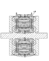
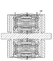
本発明の超電導回転機器の特徴を図5、及び図6を用いて説明する。
図5によれば、モータの性能(出力)は永久磁石12を通過する超電導コイル11により形成される磁束の大きさで決定される。従って、永久磁石に到達する磁束が、途中で漏れることを防ぐ必要がある。この磁束漏れを防ぐ最も有効な手段は、鉄芯13と超電導コイル11の距離を縮めること及び鉄芯13の長さを対応する超電導コイル11の軸方向の幅に近づけることである。このような構造とすることにより、図5における破線箇所(8箇所のうち1箇所をA部として示す)に示すように永久磁石上の磁束密度を高くすることができる。
[5] Features of the superconducting rotating device of the present invention The features of the superconducting rotating device of the present invention will be described with reference to FIGS.
According to FIG. 5, the performance (output) of the motor is determined by the magnitude of the magnetic flux formed by the
一方、図6に示すように、従来技術である冷却冷媒流出入口5,6、及び電流導入端子21〜24を該円筒形状の上部蓋部もしくは下部底板部又は平面部である側面部の真空断熱層部に配設すると、超電導コイルと電磁鋼板は十分に近接しているものの、鉄芯の長さは、内槽側面平板部の真空断熱層の厚みにより、超電導コイルの軸方向の幅に比べて長くなる。その結果、磁束漏れにより鉄芯上の磁束密度は図6における破線箇所(8箇所のうち1箇所をB部として示す)に示すように相対的に低くなる。
尚、通常、磁束線に垂直な面積S(m2)の平面を通過する磁束線の数Φは、Φ=BSで表される。(ここで、Bは、磁束密度であり、B=μH(μは透磁率で、Hは磁場の強さ(A/m)で示される。)
On the other hand, as shown in FIG. 6, the cooling refrigerant inflow /
In general, the number Φ of magnetic flux lines passing through a plane having an area S (m 2 ) perpendicular to the magnetic flux lines is represented by Φ = BS. (Here, B is the magnetic flux density, and B = μH (μ is the magnetic permeability, and H is the magnetic field strength (A / m)).
超電導コイルに電流を流すことで磁束が発生する。その磁束は電機子鉄芯を通り、鉄芯端面(エアギャップ)に電磁力を発生させる。この電磁力の強さはコイルの巻数と電流の積に比例し、トルクはこの電磁力と鎖交磁束数(鎖交磁束数とは、「永久磁石が作る磁束のうち鉄芯を通るもの、巻線型の場合界磁巻き線が作る磁束のうち電機子鉄芯を通るもの」をいう)に比例する。一方、鉄芯の長さが長くなれば、磁気抵抗が大きくなり、漏れ磁束が増えることは知られている。定性的には、漏れ磁束が増加すると、鎖交磁束数が減少しトルクが低下してしまう。
従って、本発明において、鉄芯の長さを超電導コイルの軸方向の幅に近づけることにより、即ち、コイルの巻かれていない鉄芯の部分を少なくすることで、漏れ磁束を防いで鎖交磁束数の減少を防ぐことにより、トルクを向上させることができる。
Magnetic flux is generated by passing a current through the superconducting coil. The magnetic flux passes through the armature core and generates electromagnetic force on the end surface (air gap) of the core. The strength of this electromagnetic force is proportional to the product of the number of turns of the coil and the current, and the torque is the electromagnetic force and the number of magnetic flux linkages (the number of magnetic flux linkages is “of the magnetic flux created by the permanent magnet that passes through the iron core, In the case of the winding type, the magnetic flux generated by the field winding is proportional to the one that passes through the armature core). On the other hand, it is known that as the length of the iron core increases, the magnetic resistance increases and the leakage flux increases. Qualitatively, when the leakage flux increases, the number of flux linkages decreases and the torque decreases.
Therefore, in the present invention, the length of the iron core is brought close to the axial width of the superconducting coil, that is, the portion of the iron core around which the coil is not wound is reduced, thereby preventing leakage flux and interlinkage magnetic flux. By preventing the number from decreasing, the torque can be improved.
本発明の超電導回転機器で使用可能な冷却媒体としては、特に限定されるものではないが、液体窒素の使用が可能であるので真空断熱構造を簡素化することが可能である。超電導は、電気抵抗をゼロにすることができるため、エネルギー効率を上げることができ、その結果空気中への無駄な熱の放出を防ぐことが出来る。
また、超電導は従来よりも200倍以上の電流を流すことができるので、装置の小型化、軽量化が可能となり、船舶用電機推進装置用モータ、鉄道用モータ、その他種々の用途に使用が可能である。
The cooling medium that can be used in the superconducting rotary device of the present invention is not particularly limited, but since liquid nitrogen can be used, the vacuum heat insulating structure can be simplified. Since superconductivity can make the electric resistance zero, energy efficiency can be increased, and as a result, useless release of heat into the air can be prevented.
In addition, since superconductivity can flow more than 200 times the current, it is possible to reduce the size and weight of the device, and it can be used for motors for marine electric propulsion devices, motors for railways, and other various applications. It is.
1 外槽
2 内槽
3 真空断熱層
4 冷却媒体
5 冷却媒体流入口
6 冷却媒体流出口
11 超電導コイル
12 永久磁石
13 鉄芯
14 サブヨーク
15 メインヨーク
16 ドライブシャフト
21 U相
22 V相
23 W相
24 中性線
25 平面部
26 冷却媒体配管用貫通継手及び電流導入端子用の貫通継手
27 ドライブシャフト配設部
28 鉄芯配設部
29 座部
31 磁束線
DESCRIPTION OF
Claims (6)
該内槽内には超電導コイルを冷却するために外槽壁と内槽壁に配設された冷却媒体配管用貫通継手を介して循環される冷却媒体が収容されており、更に外槽と内槽との間の空間が真空断熱層とされた超電導回転機器であって、
該内槽の胴部に冷却媒体配管用貫通継手及び電流導入端子用貫通継手が配設されていることを特徴とする超電導回転機器。 A superconducting coil is disposed around the iron core as an armature on at least the stator side of the rotor and the stator facing each other with a gap between the magnetic pole surfaces in parallel with each other, and the superconducting coil is disposed in the outer tub. And the overall shape of the outer shape is housed in the inner tank of the inner and outer double wall structure tank with the inner tank that is a cylindrical container,
The inner tank contains a cooling medium that is circulated through the outer tank wall and a cooling medium pipe penetration joint disposed on the inner tank wall in order to cool the superconducting coil. It is a superconducting rotating device in which the space between the tank is a vacuum heat insulating layer,
A superconducting rotary device, wherein a through-joint for cooling medium piping and a through-joint for current introduction terminal are disposed in a body portion of the inner tank.
Priority Applications (1)
| Application Number | Priority Date | Filing Date | Title |
|---|---|---|---|
| JP2008160706A JP5341405B2 (en) | 2008-06-19 | 2008-06-19 | Superconducting rotating equipment |
Applications Claiming Priority (1)
| Application Number | Priority Date | Filing Date | Title |
|---|---|---|---|
| JP2008160706A JP5341405B2 (en) | 2008-06-19 | 2008-06-19 | Superconducting rotating equipment |
Publications (2)
| Publication Number | Publication Date |
|---|---|
| JP2010004646A true JP2010004646A (en) | 2010-01-07 |
| JP5341405B2 JP5341405B2 (en) | 2013-11-13 |
Family
ID=41585878
Family Applications (1)
| Application Number | Title | Priority Date | Filing Date |
|---|---|---|---|
| JP2008160706A Active JP5341405B2 (en) | 2008-06-19 | 2008-06-19 | Superconducting rotating equipment |
Country Status (1)
| Country | Link |
|---|---|
| JP (1) | JP5341405B2 (en) |
Cited By (6)
| Publication number | Priority date | Publication date | Assignee | Title |
|---|---|---|---|---|
| JP2012152019A (en) * | 2011-01-19 | 2012-08-09 | Ihi Corp | Axial gap type rotating machine |
| JP2012228177A (en) * | 2012-07-26 | 2012-11-15 | Sumitomo Electric Ind Ltd | Superconducting coil apparatus, superconducting apparatus, and method of manufacturing superconducting coil apparatus |
| US8787998B2 (en) | 2010-01-08 | 2014-07-22 | Sumitomo Electric Industries, Ltd. | Superconducting coil apparatus, superconducting appatatus, and method of making superconducting coil apparatus |
| JP2015176882A (en) * | 2014-03-13 | 2015-10-05 | 大陽日酸株式会社 | Frp cryostat |
| JP2017096430A (en) * | 2015-11-26 | 2017-06-01 | 公益財団法人鉄道総合技術研究所 | Superconductive magnetic bearing for superconductive flywheel storage device |
| CN111934489A (en) * | 2020-07-07 | 2020-11-13 | 华中科技大学 | Superconducting cryostat for reducing alternating current loss |
Citations (2)
| Publication number | Priority date | Publication date | Assignee | Title |
|---|---|---|---|---|
| JP2007214546A (en) * | 2006-01-12 | 2007-08-23 | Taiyo Nippon Sanso Corp | Manufacturing method of frp cryostat |
| JP2008005653A (en) * | 2006-06-23 | 2008-01-10 | Ihi Corp | Superconducting coil apparatus and inductor type synchronous machine |
-
2008
- 2008-06-19 JP JP2008160706A patent/JP5341405B2/en active Active
Patent Citations (2)
| Publication number | Priority date | Publication date | Assignee | Title |
|---|---|---|---|---|
| JP2007214546A (en) * | 2006-01-12 | 2007-08-23 | Taiyo Nippon Sanso Corp | Manufacturing method of frp cryostat |
| JP2008005653A (en) * | 2006-06-23 | 2008-01-10 | Ihi Corp | Superconducting coil apparatus and inductor type synchronous machine |
Cited By (6)
| Publication number | Priority date | Publication date | Assignee | Title |
|---|---|---|---|---|
| US8787998B2 (en) | 2010-01-08 | 2014-07-22 | Sumitomo Electric Industries, Ltd. | Superconducting coil apparatus, superconducting appatatus, and method of making superconducting coil apparatus |
| JP2012152019A (en) * | 2011-01-19 | 2012-08-09 | Ihi Corp | Axial gap type rotating machine |
| JP2012228177A (en) * | 2012-07-26 | 2012-11-15 | Sumitomo Electric Ind Ltd | Superconducting coil apparatus, superconducting apparatus, and method of manufacturing superconducting coil apparatus |
| JP2015176882A (en) * | 2014-03-13 | 2015-10-05 | 大陽日酸株式会社 | Frp cryostat |
| JP2017096430A (en) * | 2015-11-26 | 2017-06-01 | 公益財団法人鉄道総合技術研究所 | Superconductive magnetic bearing for superconductive flywheel storage device |
| CN111934489A (en) * | 2020-07-07 | 2020-11-13 | 华中科技大学 | Superconducting cryostat for reducing alternating current loss |
Also Published As
| Publication number | Publication date |
|---|---|
| JP5341405B2 (en) | 2013-11-13 |
Similar Documents
| Publication | Publication Date | Title |
|---|---|---|
| JP5341405B2 (en) | Superconducting rotating equipment | |
| KR101600648B1 (en) | Generator for a wind energy installation and methd for its production | |
| US20160226353A1 (en) | Stator-plate overmoulding | |
| JP5567311B2 (en) | Axial gap motor, compressor, motor system, and generator | |
| EP0111764B1 (en) | Stator of submerged pump | |
| EP2264860B1 (en) | A rotor for a track-bound vehicle electric machine, such a machine and a track-bound vehicle having such a machine | |
| US8787998B2 (en) | Superconducting coil apparatus, superconducting appatatus, and method of making superconducting coil apparatus | |
| JP5442388B2 (en) | Magnetic iron core and manufacturing method thereof, axial gap type rotating electric machine, stationary machine | |
| CA2660731C (en) | Superconducting machine stator | |
| US9203269B2 (en) | Constructing an electric machine | |
| EP4080744A1 (en) | Pole piece device for magnetic gear, magnetic gear, and production method for pole piece device for magnetic gear | |
| US9742224B2 (en) | Pole shoe of a generator, preferably a generator of a wind turbine generator system | |
| JPWO2020071037A1 (en) | Rotating machine | |
| JP5271003B2 (en) | FRP cryostat | |
| JP2013176210A (en) | Rotor for rotary electric machine and method of manufacturing the same | |
| JP5548050B2 (en) | FRP cryostat | |
| JP2004304995A (en) | Exciter, field unit, and motor using same | |
| JP2004289966A (en) | Structure of laminated can for ammonia canned motor and processing method therefor | |
| WO2024080143A1 (en) | Core unit and rotor | |
| JP6300115B2 (en) | Electric motor cooling structure | |
| JP2024057272A (en) | Core unit and rotor | |
| US20220200423A1 (en) | Stator housing for an axial flux machine | |
| JP2021114823A (en) | Manufacturing method of rotor core | |
| JP5516665B2 (en) | Superconducting coil device, superconducting device, and method of manufacturing superconducting coil device | |
| JPS607369B2 (en) | superconducting coil |
Legal Events
| Date | Code | Title | Description |
|---|---|---|---|
| A621 | Written request for application examination |
Free format text: JAPANESE INTERMEDIATE CODE: A621 Effective date: 20110513 |
|
| A977 | Report on retrieval |
Free format text: JAPANESE INTERMEDIATE CODE: A971007 Effective date: 20121115 |
|
| A131 | Notification of reasons for refusal |
Free format text: JAPANESE INTERMEDIATE CODE: A131 Effective date: 20121128 |
|
| A521 | Request for written amendment filed |
Free format text: JAPANESE INTERMEDIATE CODE: A523 Effective date: 20130124 |
|
| TRDD | Decision of grant or rejection written | ||
| A01 | Written decision to grant a patent or to grant a registration (utility model) |
Free format text: JAPANESE INTERMEDIATE CODE: A01 Effective date: 20130723 |
|
| A61 | First payment of annual fees (during grant procedure) |
Free format text: JAPANESE INTERMEDIATE CODE: A61 Effective date: 20130808 |
|
| R150 | Certificate of patent or registration of utility model |
Ref document number: 5341405 Country of ref document: JP Free format text: JAPANESE INTERMEDIATE CODE: R150 Free format text: JAPANESE INTERMEDIATE CODE: R150 |
|
| R250 | Receipt of annual fees |
Free format text: JAPANESE INTERMEDIATE CODE: R250 |
|
| R250 | Receipt of annual fees |
Free format text: JAPANESE INTERMEDIATE CODE: R250 |
|
| R250 | Receipt of annual fees |
Free format text: JAPANESE INTERMEDIATE CODE: R250 |
|
| R250 | Receipt of annual fees |
Free format text: JAPANESE INTERMEDIATE CODE: R250 |
|
| R250 | Receipt of annual fees |
Free format text: JAPANESE INTERMEDIATE CODE: R250 |
|
| S111 | Request for change of ownership or part of ownership |
Free format text: JAPANESE INTERMEDIATE CODE: R313115 |
|
| R350 | Written notification of registration of transfer |
Free format text: JAPANESE INTERMEDIATE CODE: R350 |
|
| R250 | Receipt of annual fees |
Free format text: JAPANESE INTERMEDIATE CODE: R250 |
|
| R250 | Receipt of annual fees |
Free format text: JAPANESE INTERMEDIATE CODE: R250 |
|
| R250 | Receipt of annual fees |
Free format text: JAPANESE INTERMEDIATE CODE: R250 |