JP2010004609A - Motor - Google Patents
Motor Download PDFInfo
- Publication number
- JP2010004609A JP2010004609A JP2008159221A JP2008159221A JP2010004609A JP 2010004609 A JP2010004609 A JP 2010004609A JP 2008159221 A JP2008159221 A JP 2008159221A JP 2008159221 A JP2008159221 A JP 2008159221A JP 2010004609 A JP2010004609 A JP 2010004609A
- Authority
- JP
- Japan
- Prior art keywords
- hole
- rotor yoke
- motor
- shaft
- lightening
- Prior art date
- Legal status (The legal status is an assumption and is not a legal conclusion. Google has not performed a legal analysis and makes no representation as to the accuracy of the status listed.)
- Granted
Links
Images

Abstract
Description
本発明は、モータに関するものである。 The present invention relates to a motor.
ハイブリッド車両や燃料電池車両等の自動車の動力源として、モータが用いられている。モータは、筒状のステータ部と、ステータ部の内側に配置された円柱状のロータ部と、ロータ部の中心に同軸状に圧入固定され回転可能に支持されたシャフトとを備えている。ロータ部は、複数の磁性板材が積層されたロータヨークを備えている。ロータヨークには、モータの軽量化および運転効率向上のため、軸方向に貫通する第1肉抜き孔が設けられている。またロータヨークの端面から軸方向に沿って収容孔が形成され、この収容孔内に永久磁石が収容されている。この永久磁石が収容孔から飛び出すのを防止するため、ロータヨークの軸方向両端部には端面板が設けられている。端面板にも、ロータヨークと同様に第2肉抜き孔が設けられている。 A motor is used as a power source for automobiles such as hybrid vehicles and fuel cell vehicles. The motor includes a cylindrical stator portion, a columnar rotor portion disposed inside the stator portion, and a shaft that is coaxially press-fitted and rotatably supported at the center of the rotor portion. The rotor portion includes a rotor yoke in which a plurality of magnetic plate materials are stacked. The rotor yoke is provided with a first through hole penetrating in the axial direction in order to reduce the weight of the motor and improve the operation efficiency. An accommodation hole is formed along the axial direction from the end face of the rotor yoke, and a permanent magnet is accommodated in the accommodation hole. In order to prevent the permanent magnet from jumping out of the accommodation hole, end face plates are provided at both axial ends of the rotor yoke. Similarly to the rotor yoke, the end face plate is also provided with a second cutout hole.
特許文献1には、軸方向に複数の空洞部が設けられ、この空洞部への磁束漏れを防ぐための永久磁石が軸方向に設けられた回転子鉄心と、この回転子鉄心の両側面を押さえるための押え板とを有する回転電機の回転子において、前記押え板に前記回転子鉄心の空洞部に対応する開口部を設けるとともに、前記空洞部と開口部により形成される空洞に仕切り板を設け、その端部を回転子の側面からはみ出すようにした回転電機の回転子が記載されている。押え板に回転子鉄心の空洞部に対応する開口部を設けたことで、回転電機が駆動して回転子が回転したときに、開口部を介して空洞部に空気が流れるので、回転子を冷却することができるとされている。また、空洞部と開口部により形成される空洞に回転子の側面からはみ出すように仕切り板を設けたことで、空洞部への空気の流れが良好になるので、回転子をより冷却することができ、もって回転電機の冷却性能を向上させることができるとされている。
しかしながら、特許文献1に記載された技術では、仕切り板を利用するため、コストおよび重量が増加するという問題がある。また仕切り板を利用するため、高回転領域では空気抵抗によるモータ運転効率の低下が著しい。特に冷却油中で使用するモータの場合には、さらに運転効率が低下するという問題がある。
そこで本発明は、運転効率を低下させることなく冷却性能を向上させることが可能なモータの提供を課題とする。
However, the technique described in Patent Document 1 has a problem that the cost and weight increase because the partition plate is used. Further, since the partition plate is used, the motor operation efficiency is significantly reduced due to air resistance in the high rotation region. In particular, in the case of a motor used in cooling oil, there is a problem that operation efficiency is further reduced.
Therefore, an object of the present invention is to provide a motor capable of improving the cooling performance without reducing the operation efficiency.
上記課題を解決するために、請求項1に係る発明は、回転可能に支持されたシャフト(例えば、実施形態におけるシャフト24)と、前記シャフトに対して同軸状に圧入固定された円柱状のロータヨーク(例えば、実施形態におけるロータヨーク61)と、前記ロータヨークの端面(例えば、実施形態における端面61a)から軸方向に沿って形成された複数の第1肉抜き孔(例えば、実施形態における第1肉抜き孔70)と、前記第1肉抜き孔より径方向の外側に配置され前記端面に開口して永久磁石(例えば、実施形態における永久磁石63)を収容する収容孔(例えば、実施形態における収容孔62)と、前記軸方向における前記ロータヨークの端部に配置され前記収容孔の開口部を閉塞する端面板(例えば、実施形態における端面板80)と、前記端面板に形成された複数の第2肉抜き孔(例えば実施形態における第2肉抜き孔90)と、を備え、前記軸方向から見て、全ての前記第1肉抜き孔の少なくとも一部が、前記第2肉抜き孔を通して露出していることを特徴とする。
In order to solve the above-mentioned problem, the invention according to claim 1 includes a shaft that is rotatably supported (for example, the
請求項2に係る発明は、前記径方向における前記第2肉抜き孔の最外部(例えば、実施形態における最外部91)を通る円周の直径(例えば、実施形態における直径φb)は、前記径方向における前記第1肉抜き孔の最外部(例えば、実施形態における最外部71)を通る円周の直径(例えば、実施形態における直径φa)より大きくなっていることを特徴とする。
In the invention according to claim 2, the diameter of the circumference (for example, the diameter φb in the embodiment) passing through the outermost portion (for example, the
請求項3に係る発明は、前記シャフトの中心軸から前記径方向における前記第2肉抜き孔の最内部(例えば、実施形態における最内部92)までの距離(例えば、実施形態における距離Rb)は、前記中心軸から前記径方向における前記第1肉抜き孔の最内部(例えば、実施形態における最内部72)までの距離(例えば、実施形態における距離Ra)より小さくなっていることを特徴とする。
In the invention according to claim 3, the distance (for example, the distance Rb in the embodiment) from the central axis of the shaft to the innermost portion (for example, the innermost 92 in the embodiment) of the second hollow hole in the radial direction is The distance from the central axis to the innermost portion (for example, the
請求項4に係る発明は、前記第1肉抜き孔は、多角形状に形成され、前記軸方向から見て、前記第1肉抜き孔の全ての角部(例えば、実施形態における角部73,74,75)が、前記第2肉抜き孔を通して露出していることを特徴とする。
In the invention according to claim 4, the first lightening hole is formed in a polygonal shape, and when viewed from the axial direction, all the corners of the first lightening hole (for example, the
請求項5に係る発明は、前記端面板における前記ロータヨーク側の端面の周縁部には、前記収容孔の開口部を閉塞する凸部(例えば、実施形態における環状板82)が形成され、前記径方向における前記凸部の最内部(例えば、実施形態における底面96)を通る円周の直径(例えば、実施形態における直径φc)は、前記径方向における前記第1肉抜き孔の最外部(例えば、実施形態における最外部71)を通る円周の直径(例えば、実施形態における直径φa)より大きくなっていることを特徴とする。
In the invention according to claim 5, a convex portion (for example, the
請求項6に係る発明は、前記端面板は、前記収容孔の開口部を閉塞する環状板(例えば、実施形態における環状板82)と、前記環状板を前記ロータヨークとの間で挟持するとともに前記シャフトに圧入固定された支持板(例えば、実施形態における支持板84)と、を備え、前記環状板は非磁性材料からなり、前記支持板は前記シャフトと同等の線膨張係数を有する材料からなり、前記凸部は、前記環状板によって構成されていることを特徴とする。
The invention according to claim 6 is characterized in that the end face plate sandwiches the annular plate between the annular plate (for example, the
請求項7に係る発明は、前記支持板は、中央部が前記ロータヨークに向けて撓み変形した状態で前記シャフトに圧入固定されていることを特徴とする。 The invention according to claim 7 is characterized in that the support plate is press-fitted and fixed to the shaft in a state where the central portion is bent and deformed toward the rotor yoke.
請求項1に係る発明によれば、冷却油が第1肉抜き孔に流入しても、第2肉抜き孔を通して冷却油を流出させることができる。したがって、冷却油を循環させることが可能になり、モータの冷却効率を向上させることができる。その際、特許文献1のような仕切り板を使用しないので、モータ運転効率を低下させることがない。 According to the first aspect of the present invention, even if the cooling oil flows into the first lightening hole, the cooling oil can flow out through the second lightening hole. Therefore, it becomes possible to circulate the cooling oil, and the cooling efficiency of the motor can be improved. In that case, since a partition plate like patent document 1 is not used, motor operation efficiency is not reduced.
請求項2に係る発明によれば、シャフトの下方の第1肉抜き孔に流入した冷却油が、端面板によって堰き止められることなく、第2肉抜き孔を通って流出する。したがって、冷却油を循環させることが可能になり、モータの冷却効率を向上させることができる。 According to the second aspect of the present invention, the cooling oil that has flowed into the first cutout hole below the shaft flows out through the second cutout hole without being blocked by the end face plate. Therefore, it becomes possible to circulate the cooling oil, and the cooling efficiency of the motor can be improved.
請求項3に係る発明によれば、シャフトの上方の第1肉抜き孔に流入した冷却油が、端面板によって堰き止められることなく、第2肉抜き孔を通って流出する。したがって、冷却油を循環させることが可能になり、モータの冷却効率を向上させることができる。 According to the invention of claim 3, the cooling oil that has flowed into the first cutout hole above the shaft flows out through the second cutout hole without being blocked by the end face plate. Therefore, it becomes possible to circulate the cooling oil, and the cooling efficiency of the motor can be improved.
ロータヨークの回転状態では、第1肉抜き孔に流入した冷却油が遠心力を受けて、多角形状に形成された第1肉抜き孔のいずれかの角部に集中することになる。
請求項4に係る発明によれば、第1肉抜き孔のいずれかの角部に集中した冷却油が、端面板によって堰き止められることなく、第2肉抜き孔を通って流出する。したがって、冷却油を循環させることが可能になり、モータの冷却効率を向上させることができる。
In the rotating state of the rotor yoke, the cooling oil that has flowed into the first cutout hole receives centrifugal force and concentrates at any corner of the first cutout hole formed in a polygonal shape.
According to the fourth aspect of the present invention, the cooling oil concentrated on any one corner of the first cutout hole flows out through the second cutout hole without being blocked by the end face plate. Therefore, it becomes possible to circulate the cooling oil, and the cooling efficiency of the motor can be improved.
請求項5に係る発明によれば、ロータヨークと端面板との間に溝部が形成される。そのため、第1肉抜き孔に流入した冷却油は、端面板によって堰き止められることなく、溝部に流出する。したがって、冷却油を循環させることが可能になり、モータの冷却効率を向上させることができる。またロータヨークおよび端面板を周方向に位置決めする必要がなく、製造工程を簡略化することができる。 According to the invention which concerns on Claim 5, a groove part is formed between a rotor yoke and an end surface board. Therefore, the cooling oil that has flowed into the first cutout hole flows out into the groove without being blocked by the end face plate. Therefore, it becomes possible to circulate the cooling oil, and the cooling efficiency of the motor can be improved. Further, it is not necessary to position the rotor yoke and the end face plate in the circumferential direction, and the manufacturing process can be simplified.
請求項6に係る発明によれば、環状板が非磁性材料で構成されているので、端面板を介した磁束の短絡を抑制することができる。また支持板がシャフトと同等の線膨張係数を有する材料で構成されているので、モータが運転により発熱しても、シャフトに対する端面板の固定を維持することができる。そして、ロータヨークと支持板との間に、環状板の内周面を底面とする溝部が形成され、第1肉抜き孔に流入した冷却油がこの溝部に流出する。したがって、冷却油を循環させることが可能になり、モータの冷却効率を向上させることができる。 According to the invention which concerns on Claim 6, since the cyclic | annular board is comprised with the nonmagnetic material, the short circuit of the magnetic flux through an end surface board can be suppressed. Further, since the support plate is made of a material having a linear expansion coefficient equivalent to that of the shaft, the end face plate can be fixed to the shaft even if the motor generates heat during operation. And the groove part which makes the inner peripheral surface of a cyclic | annular board the bottom face is formed between a rotor yoke and a support plate, and the cooling oil which flowed into the 1st cut-out hole flows out into this groove part. Therefore, it becomes possible to circulate the cooling oil, and the cooling efficiency of the motor can be improved.
請求項7に係る発明によれば、撓み変形した支持板の復元力により、環状板がロータヨークに向けて押圧されるので、収容孔から永久磁石が飛び出すのを確実に防止することができる。この場合でも、ロータヨークと支持板との間に環状板の内周面を底面とする溝部が形成され、モータの冷却効率を向上させることができる。 According to the seventh aspect of the invention, since the annular plate is pressed toward the rotor yoke by the restoring force of the support plate that has been bent and deformed, it is possible to reliably prevent the permanent magnet from jumping out of the accommodation hole. Even in this case, a groove portion whose bottom surface is the inner peripheral surface of the annular plate is formed between the rotor yoke and the support plate, so that the cooling efficiency of the motor can be improved.
以下、本発明の実施形態につき図面を参照して説明する。
(車両用駆動モータユニット)
図1は車両用駆動モータユニットの概略構成断面図である。
図1に示すように、車両用駆動モータユニット(以下、モータユニットという。)10は、ステータ部21及びロータ部60を備えたモータ23を収容するモータハウジング11と、モータハウジング11の軸方向一方側に締結され、モータ23のシャフト(シャフト)24からの動力を伝達する動力伝達部(不図示)を収容するミッションハウジング12と、モータハウジング11の軸方向他方側に締結され、モータ23の回転センサ25を収容するセンサハウジング13と、を備えている。なおミッションハウジング12は、モータハウジング11に締結された共用ハウジング12Aと、共用ハウジング12Aに締結されたギアハウジング12Bとで構成されている。またモータハウジング11の内部にはモータ室36が、ミッションハウジング12の内部にはミッション室37が、センサハウジング13の内部にはセンサ室38が、それぞれ形成されている。
Hereinafter, embodiments of the present invention will be described with reference to the drawings.
(Vehicle drive motor unit)
FIG. 1 is a schematic sectional view of a vehicle drive motor unit.
As shown in FIG. 1, a vehicle drive motor unit (hereinafter referred to as a motor unit) 10 includes a motor housing 11 that houses a
モータハウジング11は、モータ23全体を覆うような略円筒形状で形成されている。モータハウジング11の内部には、モータ23を冷却するためのウォータジャケット55が、ステータ部21の全周を覆うように設けられている。また、ステータ部21は、モータハウジング11に焼き嵌めされており、モータハウジング11の内周面に密着するように配されている。
The motor housing 11 is formed in a substantially cylindrical shape so as to cover the
モータ室36とセンサ室38との仕切壁には、シャフト24の一端側を回転自在に支持するベアリング27が固定されている。一方、モータ室36とミッション室37との仕切壁には、シャフト24の他端側を回転自在に支持するベアリング26が固定されている。
モータユニット10の内部には、ベアリング26,27やモータ23等を冷却するための冷却油40が導入されている。上述したモータ23は、ステータ部21の下部が冷却油40に浸漬された状態で配置されている。またミッション室37にはオイルポンプ41が設けられており、オイルポンプ41により汲み上げられた冷却油40が、油路42を通ってモータユニット10内を循環するように構成されている。そして、モータユニット10内を循環する冷却油40がベアリング26,27等に供給されることで、ベアリング26,27等が冷却されるようになっている。
A bearing 27 that rotatably supports one end side of the
Inside the
(モータ)
本実施形態のモータ23は、インナーロータ型のモータであって、筒状のステータ部21と、ステータ部21の内側に配置された円柱状のロータ部60と、ロータ部60の中心に同軸状に圧入固定され回転可能に支持されたシャフト24と、を備えている。
ステータ部21は、磁性板材が軸方向に積層されたものであって、径方向内側に向かって延びるティース21aを備えている。このティース21aには、インシュレータ(不図示)を介してコイル21bが巻装されている。
(motor)
The
The
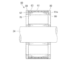
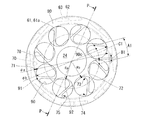
図2および図3は、第1実施形態に係るモータのロータ部の説明図であり、図2は図3のP−P線における断面図であり、図3は側面図である。図2に示すように、ロータ部60は、磁性板材が積層されたロータヨーク61を備えている。ロータヨーク61の径方向中央部には、シャフト24が固定されている。シャフト24の周囲には、ロータヨーク61を軸方向に貫通する複数(例えば8個)の第1肉抜き孔70が設けられている。具体的には、図3に示すように、ロータヨーク61の中央部と周縁部との間に複数のリブ78が掛け渡され、隣接するリブ78の間に第1肉抜き孔70が形成されている。リブ78は、シャフト24の外周に対する接線方向の片側に延設され、ロータヨーク61の周方向に沿って均等に配置されている。これにより、第1肉抜き孔70は略三角形状に形成されている。
2 and 3 are explanatory views of the rotor portion of the motor according to the first embodiment, FIG. 2 is a cross-sectional view taken along the line PP in FIG. 3, and FIG. 3 is a side view. As shown in FIG. 2, the
図2に戻り、第1肉抜き孔70の径方向外側には、ロータヨーク61を軸方向に貫通する複数の収容孔62が形成されている。各収容孔62の内部には、ネオジウム等の希土類からなる永久磁石63が挿入されている。この永久磁石63は、ロータヨーク61の径方向に磁化されている。また図3に示すように、永久磁石63はロータヨーク61の周方向に沿って略等間隔に配置され、周方向に隣接する永久磁石63は交互に逆方向に着磁されている。なお図2に示すように、永久磁石63はロータヨーク61の軸方向に沿って複数に分割されている。このように永久磁石63を複数に分割することで、永久磁石63に発生する渦電流損失を低減することができる。
Returning to FIG. 2, a plurality of receiving
図2に示すように、ロータヨーク61の軸方向に沿って複数に分割された永久磁石63は、相互に反発するため収容孔62から飛び出すおそれがある。そこで、ロータヨーク61の軸方向両端部に端面板80,80が配置されている。端面板80はシャフト24に圧入固定され、その周縁部において収容孔62の開口部を閉塞している。これにより、収容孔62から永久磁石が飛び出すのを防止している。
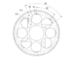
図3に示すように、シャフト24の周囲には、端面板80を軸方向に貫通する複数(例えば8個)の第2肉抜き孔90が形成されている。第2肉抜き孔90は、例えば円形状とされ、端面板80の周方向に均等に配置されている。
As shown in FIG. 2, the
As shown in FIG. 3, around the
(第1肉抜き孔、第2肉抜き孔)
ロータヨーク61の第1肉抜き孔70および端面板80の第2肉抜き孔90は、以下の相対関係を満たすように形成されている。
図3に示すように、ある円周上において、隣接する第2肉抜き孔90間の距離は、第1肉抜き孔70の開口幅より長くなっている。例えば、第2肉抜き孔90の中心90cを通る円周C1上において、隣接する第2肉抜き孔90間の距離B1は、第1肉抜き孔70の開口幅A1より長くなっている。その結果、ロータヨーク61の軸方向から見て、全ての第1肉抜き孔70の少なくとも一部が、第2肉抜き孔90を通して露出することになる。これにより、冷却油が第1肉抜き孔70に流入しても、第2肉抜き孔90を通して冷却油を流出させることができる。したがって、冷却油を循環させることが可能になり、モータの冷却効率を向上させることができる。また冷却油が第1肉抜き孔70に滞留しないので、冷却油によるロータヨーク61の劣化を防止することができる。
(First and second cutout holes)
The
As shown in FIG. 3, on a certain circumference, the distance between the adjacent second lightening holes 90 is longer than the opening width of the first lightening holes 70. For example, on a circumference C <b> 1 passing through the
また、ロータヨーク61の径方向における第2肉抜き孔90の最外部91は、第1肉抜き孔70の最外部71より外側に配置されている。すなわち、最外部91を通る円周の直径φbは、最外部71を通る円周の直径φaより大きくなっている。これにより、シャフト24の下方の第1肉抜き孔70に流入した冷却油が、端面板80によって堰き止められることなく、第2肉抜き孔90を通って流出する。
The
また、ロータヨーク61の径方向における第2肉抜き孔90の最内部92は、第1肉抜き孔70の最内部72より内側に配置されている。すなわち、シャフト24の中心軸から最内部92までの距離Rbは、その中心軸から最内部72までの距離Raより小さくなっている。これにより、シャフト24の上方の第1肉抜き孔70に流入した冷却油が、端面板80によって堰き止められることなく、第2肉抜き孔90を通って流出する。
Further, the
ところで、ロータヨーク61の回転状態では、第1肉抜き孔70に流入した冷却油が遠心力を受けて、略三角形状に形成された第1肉抜き孔70のいずれかの角部に集中することになる。そこで本実施形態では、ロータヨーク61の軸方向から見て、略三角形状の第1肉抜き孔70における全ての角部73,74,75が、第2肉抜き孔90を通して露出する構成とした。これにより、第1肉抜き孔70のいずれかの角部に集中した冷却油が、端面板80によって堰き止められることなく、第2肉抜き孔90を通って流出する。したがって、機械損失を低減させることが可能になり、またモータ効率を向上させることが可能になる。さらに、冷却油が第1肉抜き孔70に滞留しないので、冷却油によるロータヨーク61の劣化を防止することができる。
By the way, in the rotation state of the
以上に詳述したように、本実施形態に係るモータは、ロータヨーク61の軸方向から見て、全ての第1肉抜き孔70の少なくとも一部が、第2肉抜き孔90を通して露出している構成とした。これにより、第1肉抜き孔70に流入した冷却油が、端面板80によって堰き止められることなく、第2肉抜き孔90を通して流出する。したがって、冷却油を循環させることが可能になり、モータの冷却効率を向上させることができる。また冷却油が第1肉抜き孔70に滞留しないので、冷却油によるロータヨーク61の劣化を防止することができる。
As described above in detail, in the motor according to this embodiment, at least a part of all the first lightening holes 70 is exposed through the second lightening holes 90 when viewed from the axial direction of the
(第2実施形態)
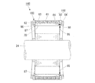
図4および図5は、第2実施形態に係るモータのロータ部の説明図であり、図4は図5のQ−Q線における断面図であり、図5は側面図である。図4に示す第2実施形態では、ロータヨーク61と端面板180との間に隙間87が形成されている点で、第1実施形態とは相違している。なお第1実施形態と同様の構成となる部分については、その詳細な説明を省略する。
(Second Embodiment)
4 and 5 are explanatory views of the rotor portion of the motor according to the second embodiment, FIG. 4 is a sectional view taken along the line Q-Q in FIG. 5, and FIG. 5 is a side view. The second embodiment shown in FIG. 4 is different from the first embodiment in that a
図2に示す第1実施形態において、端面板80が磁性材料(例えば鉄)で形成されていると、永久磁石63で発生した磁束が端面板80を介して短絡することになる。そこで、端面板80を非磁性材料(例えばステンレス)で形成することが考えられる。ところが、端面板80とシャフト24(例えば鉄製)との線膨張係数が異なると、モータの運転に伴う発熱により、シャフト24に対する端面板80の固定が緩むことになる。これにより端面板80が軸方向に移動すると、永久磁石63が収容孔62から飛び出すおそれがある。また端面板80が周方向に回転すると、モータの回転バランスが崩れるおそれがある。
In the first embodiment shown in FIG. 2, when the
これに対して、図4に示す第2実施形態では、環状板82および支持板84により端面板180が構成されている。環状板82は、永久磁石63の収容孔62の開口部を閉塞するように形成されている。この環状板82は非磁性材料(例えばステンレス)で形成されているため、端面板180を介した磁束の短絡を抑制することができる。また環状板82をロータヨーク61との間で挟持するように、円盤状の支持板84が設けられている。この支持板84(例えば鉄製)は、シャフト24と同じ線膨張係数を有している。そのため、モータが運転により発熱しても、シャフト24に対する端面板180の固定が緩むことはない。
On the other hand, in the second embodiment shown in FIG. 4, the
支持板84の中央部には、ロータヨーク61に向けて突出する円形の突出部86が形成されている。この突出部86の外周が環状板82の内周に嵌合して、環状板82が径方向に支持されている。突出部86の高さは、環状板82の厚さより小さくなっている。これにより、ロータヨーク61と支持板84との間に隙間87が形成されている。この隙間87を潰すように、支持板84の中央部がロータヨーク61に向けて撓み変形した状態で、支持板84がシャフト24に圧入固定されている。撓み変形した支持板84の復元力により、環状板82がロータヨーク61に向かって押圧されるので、収容孔62から永久磁石63が飛び出すのを確実に防止することができる。
A
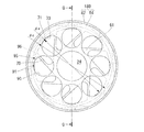
支持板84の中央部はロータヨーク61に接近しているが、支持板84の周縁部は環状板82を挟んでロータヨーク61から離間配置されている。そのためロータヨーク61と支持板84との間の周縁部には、環状板82の内周面を底面とする溝部95が形成されている。この溝部95は、ロータヨーク61の中心軸に向かって開口し、ロータヨーク61の全周にわたって形成されている。
The central portion of the
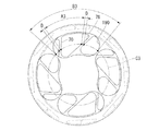
図5に示すように、溝部95の底面(すなわち、環状板82の内周面)96は、ロータヨーク61の径方向における第1肉抜き孔70の最外部71より外側に配置されている。すなわち、溝部95の底面96の直径φcは、最外部71を通る円周の直径φaより大きくなっている。これにより、第1肉抜き孔70に流入した冷却油は、ロータヨーク回転時の遠心力により溝部95に流出する。また第1実施形態と同様に、ロータヨーク61の径方向における第2肉抜き孔90の最外部91は、第1肉抜き孔70の最外部71より外側に配置されている。そのため、溝部95から溢れた冷却油は、第2肉抜き孔90を通って外部に流出する。
As shown in FIG. 5, the bottom surface of the groove portion 95 (that is, the inner peripheral surface of the annular plate 82) 96 is disposed outside the
その後、ロータヨーク61の回転が停止すると、溝部95の全周に残存する冷却油が、図4に示す隙間87を通って落下する。その冷却油は、シャフト24の下方の第2肉抜き孔90を通って外部に流出する。したがって、冷却油を循環させることが可能になり、モータの冷却効率を向上させることができる。また冷却油が第1肉抜き孔70および溝部95に滞留しないので、冷却油によるロータヨーク61の劣化を防止することができる。
Thereafter, when the rotation of the
ところで、図3に示す第1実施形態では、第2肉抜き孔90を通して第1肉抜き孔70における全ての角部73,74,75を露出させるため、ロータヨーク61および端面板80が周方向において所定の相対位置(位相)となるように、位置決めしてシャフト24に圧入する必要があった。これに対して、図5に示す第2実施形態では、冷却油の流出する溝部95が全周に形成されているため、ロータヨーク61および端面板80を周方向に位置決めする必要がない。したがって、モータの製造工程を簡略化することができる。
By the way, in the first embodiment shown in FIG. 3, the
(第3実施形態)
図6は第3実施形態に係るモータのロータ部の側面図である。第3実施形態では、上記実施形態より開口面積の大きい第1肉抜き孔170が形成されている。例えば、第2実施形態における複数(例えば8個)の第1肉抜き孔のうち、隣り合う一対の第1肉抜き孔を連結させることで、複数(例えば4個)の第1肉抜き孔170が形成されている。
これにより、隣接する第2肉抜き孔90の最外部91間の周方向距離B2が、第1肉抜き孔170の最外部171の周方向長さA2より短くなっている。この場合、ロータヨーク61の軸方向から見て、第1肉抜き孔170の最外部171の周方向長さのうち少なくとも一部が、常に第2肉抜き孔90を通して露出する。これにより、第1肉抜き孔170に流入した冷却油が、ロータヨーク61の回転状態において遠心力により最外部171に集中しても、第2肉抜き孔90を通して流出することになる。したがって、冷却油を循環させることが可能になり、モータの冷却効率を向上させることができる。また冷却油が第1肉抜き孔170に滞留しないので、冷却油によるロータヨーク61の劣化を防止することができる。
(Third embodiment)
FIG. 6 is a side view of the rotor portion of the motor according to the third embodiment. In the third embodiment, the
Thereby, the circumferential distance B2 between the
(第4実施形態)
図7は第4実施形態に係るモータのロータ部の側面図である。第4実施形態では、上記実施形態より開口面積の大きい第2肉抜き孔190が形成されている。例えば、第1実施形態における複数(例えば8個)の第2肉抜き孔のうち、隣り合う一対の第2肉抜き孔を連結させることで、複数(例えば4個)の第2肉抜き孔190が形成されている。
これにより、ある円周C3上において、第2肉抜き孔190の開口幅B3が、第1肉抜き孔70の幅A3およびその両側のリブ78の幅Dの合計幅(A3+2×D)より大きくなっていることが望ましい。この場合、第2肉抜き孔190を通して、複数の第1肉抜き孔70が露出することになる。これにより、第1肉抜き孔70に流入した冷却油が、第2肉抜き孔190を通して流出しやすくなる。したがって、冷却油を循環させることが可能になり、モータの冷却効率を向上させることができる。また冷却油が第1肉抜き孔70に滞留しないので、冷却油によるロータヨーク61の劣化を防止することができる。
(Fourth embodiment)
FIG. 7 is a side view of the rotor portion of the motor according to the fourth embodiment. In the fourth embodiment, a
Thereby, on a certain circumference C3, the opening width B3 of the
なお、本発明の技術範囲は上述した実施形態に限られるものではなく、本発明の趣旨を逸脱しない範囲において、上述した実施形態に種々の変更を加えたものを含む。すなわち、実施形態で挙げた具体的な構造や形状などはほんの一例に過ぎず、適宜変更が可能である。
例えば、実施形態では第1肉抜き孔を略三角形状とし、第2肉抜き孔を円形状としたが、第1肉抜き孔および第2肉抜き孔を他の形状とすることも可能である。
The technical scope of the present invention is not limited to the above-described embodiment, and includes various modifications made to the above-described embodiment without departing from the spirit of the present invention. That is, the specific structure and shape described in the embodiment are merely examples, and can be changed as appropriate.
For example, in the embodiment, the first cutout hole has a substantially triangular shape and the second cutout hole has a circular shape, but the first cutout hole and the second cutout hole may have other shapes. .
23…モータ 24…シャフト 60…ロータ部 61…ロータヨーク 61a…端面 62…収容孔 63…永久磁石 70…第1肉抜き孔 71…最外部 72…最内部 73,74,75…角部 80…端面板 82…環状板(凸部) 84…支持板 87…隙間 90…第2肉抜き孔 91…最外部 92…最内部 95…溝部 180…端面板
DESCRIPTION OF
Claims (7)
前記軸方向から見て、全ての前記第1肉抜き孔の少なくとも一部が、前記第2肉抜き孔を通して露出していることを特徴とするモータ。 A shaft that is rotatably supported, a cylindrical rotor yoke that is press-fitted and fixed coaxially with the shaft, a plurality of first cutout holes that are formed along an axial direction from an end surface of the rotor yoke, and An accommodation hole that is arranged on the outer side in the radial direction from the first cutout hole and that opens to the end face to accommodate the permanent magnet, and an end that is arranged at the end of the rotor yoke in the axial direction and closes the opening of the accommodation hole A face plate, and a plurality of second hollow holes formed in the end face plate,
The motor according to claim 1, wherein at least a part of all the first lightening holes are exposed through the second lightening holes when viewed from the axial direction.
前記軸方向から見て、前記第1肉抜き孔の全ての角部が、前記第2肉抜き孔を通して露出していることを特徴とする請求項1ないし請求項3のいずれか1項に記載のモータ。 The first cutout hole is formed in a polygonal shape,
4. The device according to claim 1, wherein when viewed from the axial direction, all corner portions of the first lightening hole are exposed through the second lightening hole. 5. Motor.
前記径方向における前記凸部の最内部を通る円周の直径は、前記径方向における前記第1肉抜き孔の最外部を通る円周の直径より大きくなっていることを特徴とする請求項1ないし請求項4のいずれか1項に記載のモータ。 On the peripheral edge of the end face on the rotor yoke side of the end face plate, a convex part that closes the opening of the accommodation hole is formed,
The diameter of the circumference passing through the innermost part of the convex part in the radial direction is larger than the diameter of the circumference passing through the outermost part of the first cutout hole in the radial direction. The motor according to any one of claims 4 to 4.
前記環状板は非磁性材料からなり、前記支持板は前記シャフトと同等の線膨張係数を有する材料からなり、
前記凸部は、前記環状板によって構成されていることを特徴とする請求項5に記載のモータ。 The end face plate includes an annular plate that closes the opening of the accommodation hole, and a support plate that is sandwiched between the rotor yoke and the press fitting to the shaft.
The annular plate is made of a nonmagnetic material, and the support plate is made of a material having a linear expansion coefficient equivalent to that of the shaft,
The motor according to claim 5, wherein the convex portion is constituted by the annular plate.
Priority Applications (2)
| Application Number | Priority Date | Filing Date | Title |
|---|---|---|---|
| JP2008159221A JP5139892B2 (en) | 2008-06-18 | 2008-06-18 | motor |
| US12/486,221 US7986068B2 (en) | 2008-06-18 | 2009-06-17 | Motor |
Applications Claiming Priority (1)
| Application Number | Priority Date | Filing Date | Title |
|---|---|---|---|
| JP2008159221A JP5139892B2 (en) | 2008-06-18 | 2008-06-18 | motor |
Publications (2)
| Publication Number | Publication Date |
|---|---|
| JP2010004609A true JP2010004609A (en) | 2010-01-07 |
| JP5139892B2 JP5139892B2 (en) | 2013-02-06 |
Family
ID=41585845
Family Applications (1)
| Application Number | Title | Priority Date | Filing Date |
|---|---|---|---|
| JP2008159221A Expired - Fee Related JP5139892B2 (en) | 2008-06-18 | 2008-06-18 | motor |
Country Status (1)
| Country | Link |
|---|---|
| JP (1) | JP5139892B2 (en) |
Cited By (3)
| Publication number | Priority date | Publication date | Assignee | Title |
|---|---|---|---|---|
| JP2015204653A (en) * | 2014-04-11 | 2015-11-16 | 本田技研工業株式会社 | Rotary electric machine |
| JP2017208883A (en) * | 2016-05-16 | 2017-11-24 | 本田技研工業株式会社 | Rotor of rotary electric machine and manufacturing method of rotor of rotary electric machine |
| TWI676339B (en) * | 2018-03-20 | 2019-11-01 | 元山科技工業股份有限公司 | electric motor |
Citations (4)
| Publication number | Priority date | Publication date | Assignee | Title |
|---|---|---|---|---|
| JP2003259577A (en) * | 2002-03-01 | 2003-09-12 | Toyota Motor Corp | Rotor assembly of permanent magnet motor |
| JP2003333780A (en) * | 2002-03-04 | 2003-11-21 | Asmo Co Ltd | Armature, manufacturing method of the armature, and motor |
| JP2007135371A (en) * | 2005-11-14 | 2007-05-31 | Toyota Motor Corp | Rotor for rotating electric machine |
| JP2008086130A (en) * | 2006-09-28 | 2008-04-10 | Honda Motor Co Ltd | Motor |
-
2008
- 2008-06-18 JP JP2008159221A patent/JP5139892B2/en not_active Expired - Fee Related
Patent Citations (4)
| Publication number | Priority date | Publication date | Assignee | Title |
|---|---|---|---|---|
| JP2003259577A (en) * | 2002-03-01 | 2003-09-12 | Toyota Motor Corp | Rotor assembly of permanent magnet motor |
| JP2003333780A (en) * | 2002-03-04 | 2003-11-21 | Asmo Co Ltd | Armature, manufacturing method of the armature, and motor |
| JP2007135371A (en) * | 2005-11-14 | 2007-05-31 | Toyota Motor Corp | Rotor for rotating electric machine |
| JP2008086130A (en) * | 2006-09-28 | 2008-04-10 | Honda Motor Co Ltd | Motor |
Cited By (3)
| Publication number | Priority date | Publication date | Assignee | Title |
|---|---|---|---|---|
| JP2015204653A (en) * | 2014-04-11 | 2015-11-16 | 本田技研工業株式会社 | Rotary electric machine |
| JP2017208883A (en) * | 2016-05-16 | 2017-11-24 | 本田技研工業株式会社 | Rotor of rotary electric machine and manufacturing method of rotor of rotary electric machine |
| TWI676339B (en) * | 2018-03-20 | 2019-11-01 | 元山科技工業股份有限公司 | electric motor |
Also Published As
| Publication number | Publication date |
|---|---|
| JP5139892B2 (en) | 2013-02-06 |
Similar Documents
| Publication | Publication Date | Title |
|---|---|---|
| JP5186291B2 (en) | motor | |
| US7986068B2 (en) | Motor | |
| JP5331565B2 (en) | Motor unit | |
| JP5087583B2 (en) | Electric motor and method of manufacturing electric motor | |
| US20050285474A1 (en) | Rotating electric machine | |
| JP2013172491A (en) | Rotor core, motor and method of manufacturing motor | |
| JP5696137B2 (en) | Magnetic steel sheet forming body, rotor core, rotor, rotating electrical machine, and vehicle | |
| JP6545393B2 (en) | Conscious pole rotor, motor and air conditioner | |
| JP5023100B2 (en) | Electric motor | |
| JP6085267B2 (en) | Rotating electric machine | |
| JP2006304539A (en) | Rotor structure of axial gap rotating electric machine | |
| JP6525329B2 (en) | Rotor and method of manufacturing rotor | |
| JP5139892B2 (en) | motor | |
| JP2009240109A (en) | Electric motor | |
| JP2006304532A (en) | Rotor structure of axial gap rotating electric machine | |
| JP2020010539A (en) | Rotor and brushless motor | |
| JP4966992B2 (en) | Rotor and method for manufacturing rotor | |
| JP5264567B2 (en) | motor | |
| JP2013013243A (en) | Motor | |
| JP5193114B2 (en) | Rotor and motor | |
| JP2018133948A (en) | motor | |
| JP2011101513A (en) | Motor unit and manufacturing method of the same | |
| WO2018131402A1 (en) | Permanent magnet embedded rotor and electric motor equipped with same | |
| JP2011234554A (en) | Electric motor | |
| WO2017175461A1 (en) | Axial gap rotary electric machine |
Legal Events
| Date | Code | Title | Description |
|---|---|---|---|
| A621 | Written request for application examination |
Free format text: JAPANESE INTERMEDIATE CODE: A621 Effective date: 20101125 |
|
| A977 | Report on retrieval |
Free format text: JAPANESE INTERMEDIATE CODE: A971007 Effective date: 20120718 |
|
| A131 | Notification of reasons for refusal |
Free format text: JAPANESE INTERMEDIATE CODE: A131 Effective date: 20120724 |
|
| A521 | Request for written amendment filed |
Free format text: JAPANESE INTERMEDIATE CODE: A523 Effective date: 20120921 |
|
| TRDD | Decision of grant or rejection written | ||
| A01 | Written decision to grant a patent or to grant a registration (utility model) |
Free format text: JAPANESE INTERMEDIATE CODE: A01 Effective date: 20121030 |
|
| A01 | Written decision to grant a patent or to grant a registration (utility model) |
Free format text: JAPANESE INTERMEDIATE CODE: A01 |
|
| A61 | First payment of annual fees (during grant procedure) |
Free format text: JAPANESE INTERMEDIATE CODE: A61 Effective date: 20121116 |
|
| R150 | Certificate of patent or registration of utility model |
Ref document number: 5139892 Country of ref document: JP Free format text: JAPANESE INTERMEDIATE CODE: R150 Free format text: JAPANESE INTERMEDIATE CODE: R150 |
|
| FPAY | Renewal fee payment (event date is renewal date of database) |
Free format text: PAYMENT UNTIL: 20151122 Year of fee payment: 3 |
|
| R250 | Receipt of annual fees |
Free format text: JAPANESE INTERMEDIATE CODE: R250 |
|
| LAPS | Cancellation because of no payment of annual fees |