JP2010004575A - Image transmitting apparatus, image transmitting method, and computer readable recording medium with program for making computer implement the method recorded thereon - Google Patents
Image transmitting apparatus, image transmitting method, and computer readable recording medium with program for making computer implement the method recorded thereon Download PDFInfo
- Publication number
- JP2010004575A JP2010004575A JP2009231973A JP2009231973A JP2010004575A JP 2010004575 A JP2010004575 A JP 2010004575A JP 2009231973 A JP2009231973 A JP 2009231973A JP 2009231973 A JP2009231973 A JP 2009231973A JP 2010004575 A JP2010004575 A JP 2010004575A
- Authority
- JP
- Japan
- Prior art keywords
- input
- output
- unit
- selection
- key
- Prior art date
- Legal status (The legal status is an assumption and is not a legal conclusion. Google has not performed a legal analysis and makes no representation as to the accuracy of the status listed.)
- Granted
Links
Images


Abstract
Description
本発明は、画像データを入力する、それぞれ異なる機能を有する複数の入力手段(形式)と、画像データを出力する、それぞれ異なる機能を有する複数の出力手段(形式)とを備えた画像送信装置、画像送信方法およびその方法をコンピュータに実行させるプログラムを記録したコンピュータ読み取り可能な記録媒体に関するものである。 The present invention relates to an image transmission apparatus comprising a plurality of input means (formats) having different functions for inputting image data and a plurality of output means (forms) having different functions for outputting image data, The present invention relates to an image transmission method and a computer-readable recording medium on which a program for causing a computer to execute the method is recorded.
近年、画像データ処理の多様化にともない、入力される画像データ、出力される画像データの処理工程が多様化・複雑化し、それらの処理工程を組み合わせたディジタル複合機が画像処理装置の主流となりつつある。そのディジタル複合機によれば、画像データの処理に関し、多くの機能を実現することができることが特徴となっている。 In recent years, with the diversification of image data processing, the processing steps of input image data and output image data have become diversified and complicated, and digital multi-function peripherals combining those processing steps are becoming mainstream of image processing apparatuses. is there. The digital multi-function peripheral is characterized in that many functions can be realized regarding the processing of image data.
画像処理装置の機能の向上にともなって、その画像処理装置の操作性の向上も重要となってきている。そのような状況において、画像処理装置における画像処理は、画像データの入力機能と画像データの出力機能とに分けることができる。そして、通常、入力機能と出力機能とは一連の処理として括られ、あらかじめ関連付けられ、関連付けられた入力機能と出力機能の括りを所定の処理として取り扱うようにしてきた。 As the functions of the image processing apparatus are improved, it is also important to improve the operability of the image processing apparatus. In such a situation, the image processing in the image processing apparatus can be divided into an image data input function and an image data output function. In general, the input function and the output function are bundled as a series of processes, associated in advance, and the grouping of the associated input function and output function is handled as a predetermined process.
しかしながら、入力機能と出力機能をあらかじめ関連付けて組み合わせてしまうと、組み合わせの内容によっては操作者が所望する操作をおこなうことができない、あるいは操作をするのが複雑となり、操作性が低下するという問題点があった。 However, if the input function and the output function are associated with each other in advance and combined, the operation desired by the operator cannot be performed depending on the content of the combination, or the operation becomes complicated and the operability deteriorates. was there.
また、多様な要求に応じるための想定できる機能の組み合わせごとに関連付けることにすると、その機能を指定するためのキーを機能ごとに設けなければならず、キーの数が増加する。そのため、多くのキーの中から所望の機能に該当するキーを見つけだすのが困難になる場合があるという問題点があった。特に、入力手段、出力手段の種類増加にともない、キー数が増加することは、操作の複雑化、煩雑化をまねき、操作性をより低下させてしまうことになる。 Further, if association is assumed for each combination of functions that can be assumed to meet various requirements, a key for designating the function must be provided for each function, and the number of keys increases. Therefore, there is a problem that it may be difficult to find a key corresponding to a desired function from among many keys. In particular, an increase in the number of keys accompanying an increase in the types of input means and output means leads to complicated and complicated operations and further reduces operability.
この発明は、上述の点に鑑みてなされたものであり、画像処理の多様な要求に迅速かつ容易に対応し、操作性を向上させることが可能な画像送信装置、画像送信方法およびその方法をコンピュータに実行させるプログラムを記録したコンピュータ読み取り可能な記録媒体を提供することを目的とする。 The present invention has been made in view of the above points, and provides an image transmission apparatus, an image transmission method, and a method thereof that can quickly and easily respond to various requests for image processing and improve operability. It is an object of the present invention to provide a computer-readable recording medium that records a program to be executed by a computer.
上記目的を達成するために、この発明にかかる画像処理装置は、画像データを入力する、それぞれ異なる機能を有する複数の入力手段と、画像データを出力する、それぞれ異なる機能を有する複数の出力手段とを備えた画像処理装置において、前記複数の入力手段の中から所望の入力手段を選択する第1の選択手段と、前記複数の出力手段の中から所望の出力手段を選択する第2の選択手段と、前記第1の選択手段によって選択された選択入力手段および前記第2の選択手段によって選択された選択出力手段を制御して、前記選択入力手段により入力された画像データを、前記選択出力手段により出力する処理制御手段と、を備えたことを特徴とする。 In order to achieve the above object, an image processing apparatus according to the present invention includes a plurality of input units having different functions for inputting image data, and a plurality of output units having different functions for outputting image data. In the image processing apparatus comprising: a first selection unit that selects a desired input unit from the plurality of input units; and a second selection unit that selects a desired output unit from the plurality of output units. And the selection input means selected by the first selection means and the selection output means selected by the second selection means, and the image data input by the selection input means is converted into the selection output means. And a processing control means for outputting in accordance with the above.
この発明によれば、入力手段と出力手段をそれぞれ別個に選択することができ、入力手段と出力手段の所望の組み合わせによる画像処理をおこなうことができる。 According to the present invention, the input means and the output means can be selected separately, and image processing can be performed by a desired combination of the input means and the output means.
また、この発明にかかる画像処理装置は、上記発明において、さらに、前記選択入力手段が前記第1の選択手段によって選択された際に、前記選択入力手段の画像データの入力条件を設定する入力条件設定画面を表示する第1の表示手段を備えたことを特徴とする。 In the image processing apparatus according to the present invention, the input condition for setting the image data input condition of the selection input means when the selection input means is selected by the first selection means in the above invention. A first display means for displaying a setting screen is provided.
この発明によれば、入力手段による画像データの詳細な入力条件を容易に設定することができる。 According to this invention, it is possible to easily set detailed input conditions for image data by the input means.
また、この発明にかかる画像処理装置は、上記発明において、さらに、前記選択出力手段が前記第2の選択手段によって選択された際に、前記選択出力手段の画像データの出力条件を設定する出力条件設定画面を表示する第2の表示手段を備えたことを特徴とする。 In the image processing apparatus according to the present invention, in the above invention, an output condition for setting an output condition of the image data of the selection output unit when the selection output unit is selected by the second selection unit. A second display means for displaying a setting screen is provided.
この発明によれば、出力手段による画像データの詳細な出力条件を容易に設定することができる。 According to the present invention, detailed output conditions of image data by the output means can be easily set.
また、この発明にかかる画像処理装置は、上記発明において、さらに、文字、記号、絵等から構成された、前記入力手段を示すキーを表示する第3の表示手段を備え、前記第1の選択手段が、前記第3の表示手段に表示されたキーを押下または接触することにより前記入力手段を選択することを特徴とする。 The image processing apparatus according to the present invention further comprises third display means for displaying a key indicating the input means, which is composed of characters, symbols, pictures, etc. The means selects the input means by pressing or touching a key displayed on the third display means.
この発明によれば、キーのデザインを表示画面上で変更することにより、入力手段の追加、変更、削除等を容易におこなうことができる。 According to the present invention, it is possible to easily add, change, and delete input means by changing the key design on the display screen.
また、この発明にかかる画像処理装置は、上記発明において、さらに、文字、記号、絵等から構成された、前記出力手段を示すキーを表示する第4の表示手段を備え、前記第2の選択手段が、前記第4の表示手段に表示されたキーを押下または接触することにより前記出力手段を選択することを特徴とする。 The image processing apparatus according to the present invention further comprises a fourth display means for displaying a key indicating the output means, which is composed of characters, symbols, pictures, etc. The means selects the output means by pressing or touching a key displayed on the fourth display means.
この発明によれば、キーのデザインを表示画面上で変更することにより、出力手段の追加、変更、削除等を容易におこなうことができる。 According to the present invention, it is possible to easily add, change, delete, etc. the output means by changing the key design on the display screen.
また、この発明にかかる画像処理装置は、上記発明において、前記第1の選択手段が、所望の入力手段を複数選択し、前記処理制御手段が、前記第1の選択手段によって選択された複数の選択入力手段および前記第2の選択手段によって選択された選択出力手段を制御して、前記複数の選択入力手段により入力された画像データを、前記選択出力手段により出力することを特徴とする。 In the image processing apparatus according to the present invention, in the above invention, the first selection unit selects a plurality of desired input units, and the processing control unit selects a plurality of selection units selected by the first selection unit. The selection output unit selected by the selection input unit and the second selection unit is controlled, and the image data input by the plurality of selection input units is output by the selection output unit.
この発明によれば、一度の操作で、複数の画像データを異なる入力手段から入力し、その入力したデータを出力することができる。 According to the present invention, it is possible to input a plurality of image data from different input means and output the input data with a single operation.
また、この発明にかかる画像処理装置は、上記発明において、前記第2の選択手段が、所望の出力手段を複数選択し、前記処理制御手段が、前記第1の選択手段によって選択された選択入力手段および前記第2の選択手段によって選択された複数の選択出力手段を制御して、前記選択入力手段により入力された画像データを、前記複数の選択出力手段により出力することを特徴とする。 In the image processing apparatus according to the present invention, in the above invention, the second selection unit selects a plurality of desired output units, and the processing control unit selects the selection input selected by the first selection unit. And a plurality of selection output means selected by the second selection means, and image data input by the selection input means is output by the plurality of selection output means.
この発明によれば、入力手段により入力されたデータを、一度の操作で複数の出力手段によりそれぞれ出力することができる。 According to the present invention, the data input by the input means can be output by the plurality of output means by a single operation.
また、この発明にかかる画像処理装置は、上記発明において、さらに、前記第1の選択手段により選択された選択入力手段と、前記第2の選択手段により選択された選択出力手段との組み合わせに関する情報を記憶する記憶手段を備えたことを特徴とする。 In the image processing apparatus according to the present invention, further, in the above-described invention, information relating to a combination of the selection input unit selected by the first selection unit and the selection output unit selected by the second selection unit. It is characterized by comprising storage means for storing.
この発明によれば、所望の組み合わせを次回利用する場合に改めて設定し直す必要がない。 According to the present invention, it is not necessary to set again when the desired combination is used next time.
また、この発明にかかる画像処理装置は、上記発明において、前記記憶手段により記憶された組み合わせに関する情報の中から所望の組み合わせを選択する第3の選択手段を備え、前記処理制御手段が、前記第3の選択手段によって選択された選択入力手段および選択出力手段を制御して、前記選択入力手段により入力された画像データを、前記選択出力手段により出力しまたは蓄積することを特徴とする。 The image processing apparatus according to the present invention further comprises third selection means for selecting a desired combination from the information related to the combinations stored by the storage means in the above invention, wherein the processing control means includes the first The selection input unit and the selection output unit selected by the selection unit 3 are controlled, and the image data input by the selection input unit is output or stored by the selection output unit.
この発明によれば、所望の組み合わせを容易に選択することができる。 According to the present invention, a desired combination can be easily selected.
また、この発明にかかる画像処理装置は、上記発明において、前記入力手段が、原稿画像を読み取る原稿読取ユニットおよび/または装置本体内に備えられたデータ記憶部あるいは装置本体に接続された外部装置に蓄積されたデータを入力する装置であることを特徴とする。 The image processing apparatus according to the present invention is the image processing apparatus according to the present invention, wherein the input means is a document reading unit for reading a document image and / or a data storage unit provided in the apparatus main body or an external device connected to the apparatus main body. It is a device for inputting the accumulated data.
また、この発明にかかる画像処理装置は、上記発明において、前記出力手段が、画像形成装置および/またはデータ送信装置および/または装置本体内に備えられたデータ記憶部あるいは装置本体に接続された外部装置にデータを出力しかつ蓄積する装置であることを特徴とする。 The image processing apparatus according to the present invention is the image processing apparatus according to the above invention, wherein the output means is an external device connected to an image forming apparatus and / or a data transmission apparatus and / or a data storage unit provided in the apparatus body or an apparatus body. It is a device that outputs and stores data in the device.
また、この発明にかかる画像処理システムは、上記に記載の画像処理装置および前記画像処理装置が接続されるネットワークを備えたことを特徴とする。 An image processing system according to the present invention includes the image processing apparatus described above and a network to which the image processing apparatus is connected.
また、この発明にかかる画像処理システムは、上記発明において、前記ネットワークがインターネットであることを特徴とする。 In the image processing system according to the present invention as set forth in the invention described above, the network is the Internet.
また、この発明にかかる画像処理方法は、画像データを入力する、それぞれ異なる機能を有する複数の入力工程の中から所望の入力工程を選択する第1の選択工程と、画像データを出力する、それぞれ異なる機能を有する複数の出力工程の中から所望の出力手段を選択する第2の選択工程と、前記第1の選択工程によって選択された選択入力工程により入力された画像データを、前記第2の選択工程によって選択された選択出力工程により出力する処理工程と、を含んだことを特徴とする。 The image processing method according to the present invention includes a first selection step for selecting a desired input step from a plurality of input steps each having a different function for inputting image data, and outputting the image data. A second selection step of selecting a desired output means from a plurality of output steps having different functions, and image data input in the selection input step selected in the first selection step; And a processing step of outputting in a selection output step selected in the selection step.
この発明によれば、入力工程と出力工程をそれぞれ別個に選択することができ、入力工程と出力工程の所望の組み合わせによる画像処理をおこなうことができる。 According to this invention, an input process and an output process can be selected separately, and image processing can be performed by a desired combination of the input process and the output process.
また、この発明にかかる画像処理方法は、画像データを入力する、それぞれ異なる機能を有する複数の入力工程の中から所望の入力工程を選択する第1の選択工程と、前記第1の選択工程によって選択された選択入力工程が画像データを入力する条件を設定する入力条件設定工程と、画像データを出力する、それぞれ異なる機能を有する複数の出力工程の中から所望の出力手段を選択する第2の選択工程と、前記入力条件設定工程により設定された入力条件に基づいて、前記選択入力工程により入力された画像データを、前記第2の選択工程によって選択された選択出力工程により出力する処理工程と、を含んだことを特徴とする。 The image processing method according to the present invention includes a first selection step for selecting a desired input step from among a plurality of input steps having different functions for inputting image data, and the first selection step. An input condition setting step for setting a condition for inputting image data by the selected selection input step, and a second output unit for selecting desired output means from a plurality of output steps for outputting image data, each having a different function. And a processing step of outputting the image data input by the selection input step based on the input condition set by the input condition setting step by the selection output step selected by the second selection step; , Including.
この発明によれば、入力工程による画像データの詳細な入力条件を容易に設定することができる。 According to the present invention, it is possible to easily set detailed input conditions for image data in the input process.
また、この発明にかかる画像処理方法は、画像データを入力する、それぞれ異なる機能を有する複数の入力工程の中から所望の入力工程を選択する第1の選択工程と、画像データを出力する、それぞれ異なる機能を有する複数の出力工程の中から所望の出力手段を選択する第2の選択工程と、前記第2の選択工程によって選択された選択出力工程が画像データを出力する条件を設定する出力条件設定工程と、前記選択入力工程により入力された画像データを、前記出力条件設定工程により設定された出力条件に基づいて、前記選択出力工程により出力する処理工程と、を含んだことを特徴とする。 The image processing method according to the present invention includes a first selection step for selecting a desired input step from a plurality of input steps each having a different function for inputting image data, and outputting the image data. A second selection step for selecting a desired output means from a plurality of output steps having different functions, and an output condition for setting a condition for outputting the image data by the selection output step selected by the second selection step A setting step; and a processing step of outputting the image data input by the selection input step by the selection output step based on the output condition set by the output condition setting step. .
この発明によれば、出力工程による画像データの詳細な出力条件を容易に設定することができる。 According to the present invention, it is possible to easily set detailed output conditions for image data in the output process.
また、この発明にかかる画像処理方法は、上記発明において、前記第1の選択工程が、所望の入力工程を複数選択し、前記処理工程が、前記第1の選択工程によって選択された複数の選択入力工程により入力された画像データを、前記第2の選択工程によって選択された選択出力工程により出力することを特徴とする。 In the image processing method according to the present invention, in the above invention, the first selection step selects a plurality of desired input steps, and the processing step selects a plurality of selections selected by the first selection step. The image data input in the input process is output in the selection output process selected in the second selection process.
この発明によれば、一度の操作で、複数の画像データを異なる入力工程から入力し、その入力したデータを出力することができる。 According to the present invention, it is possible to input a plurality of image data from different input processes and output the input data in one operation.
また、この発明にかかる画像処理方法は、上記発明において、前記第2の選択工程が、所望の出力工程を複数選択し、前記処理工程が、前記第1の選択工程によって選択された選択入力工程により入力された画像データを、前記第2の選択工程によって選択された複数の選択出力工程により出力することを特徴とする。 In the image processing method according to the present invention, in the above invention, the second selection step selects a plurality of desired output steps, and the processing step is a selection input step selected by the first selection step. The image data input in step (2) is output in a plurality of selection output steps selected in the second selection step.
この発明によれば、入力手段により入力されたデータを、一度の操作で複数の出力手段によりそれぞれ出力することができる。 According to the present invention, the data input by the input means can be output by the plurality of output means by a single operation.
また、この発明にかかる画像処理方法は、上記発明において、さらに、前記第1の選択工程により選択された選択入力工程と、前記第2の選択工程により選択された選択出力工程との組み合わせに関する情報の中から所望の組み合わせを選択する第3の選択工程を備えたことを特徴とする。 The image processing method according to the present invention is the image processing method according to the above-mentioned invention, wherein the selection input step selected by the first selection step and the selection output step selected by the second selection step are further information. A third selection step of selecting a desired combination from the above is provided.
この発明によれば、所望の組み合わせを次回利用する場合に改めて設定し直す必要がなく、所望の組み合わせを容易に選択することができる。 According to the present invention, it is not necessary to set again when the desired combination is used next time, and the desired combination can be easily selected.
また、この発明にかかる画像処理方法は、上記記載の発明において、前記入力工程が、原稿画像を読み取る原稿読取工程および/または蓄積されたデータを入力する工程であることを特徴とする。 The image processing method according to the present invention is characterized in that, in the above-described invention, the input step is a document reading step of reading a document image and / or a step of inputting accumulated data.
また、この発明にかかる画像処理方法は、上記記載の発明において、前記出力工程が、画像形成工程および/またはデータ送信工程および/またはデータを蓄積する工程であることを特徴とする。 The image processing method according to the present invention is characterized in that, in the above-described invention, the output step is an image forming step and / or a data transmitting step and / or a step of accumulating data.
また、この発明にかかる記録媒体は、上記に記載された方法をコンピュータに実行させるプログラムを記録したことにより、そのプログラムを機械読み取り可能となり、これによって、上記の動作をコンピュータによって実現することが可能となる。 In addition, the recording medium according to the present invention records a program that causes a computer to execute the method described above, thereby enabling the program to be machine-readable, thereby enabling the above operation to be realized by the computer. It becomes.
以上説明したように、この発明によれば、画像データを入力する、それぞれ異なる機能を有する複数の入力手段の中から所望の入力手段を選択する第1の選択手段と、画像データを出力する、それぞれ異なる機能を有する複数の出力手段の中から所望の出力手段を選択する第2の選択手段と、前記第1の選択手段によって選択された選択入力手段および前記第2の選択手段によって選択された選択出力手段を制御して、前記選択入力手段により入力された画像データを、前記選択出力手段により出力する処理制御手段と、を備えるため、入力手段と出力手段をそれぞれ別個に選択することができ、入力手段と出力手段の所望の組み合わせによる画像処理をおこなうことができ、これにより、画像処理の多様な要求に迅速かつ容易に対応し、操作性を向上させることが可能な画像処理装置が得られるという効果を奏する。 As described above, according to the present invention, the image data is input, the first selection means for selecting a desired input means from the plurality of input means having different functions, and the image data is output. A second selection means for selecting a desired output means from a plurality of output means each having a different function; a selection input means selected by the first selection means; and a selection means selected by the second selection means And a processing control means for controlling the selection output means and outputting the image data input by the selection input means by the selection output means, so that the input means and the output means can be selected separately. Therefore, it is possible to perform image processing by a desired combination of input means and output means, thereby responding quickly and easily to various requests for image processing. There is an effect that the image processing device capable of improving the sexual is obtained.
また、この発明によれば、さらに、前記選択入力手段が前記第1の選択手段によって選択された際に、前記選択入力手段の画像データの入力条件を設定する入力条件設定画面を表示する第1の表示手段を備えるため、入力手段による画像データの詳細な入力条件を容易に設定することができ、これにより、画像処理の多様な要求に迅速かつ容易に対応し、操作性を向上させることが可能な画像処理装置が得られるという効果を奏する。 Further, according to the present invention, when the selection input means is selected by the first selection means, a first input condition setting screen for setting an input condition of image data of the selection input means is displayed. Therefore, it is possible to easily set detailed input conditions of image data by the input means, thereby quickly and easily responding to various requests for image processing and improving operability. There is an effect that a possible image processing apparatus is obtained.
また、この発明によれば、さらに、前記選択出力手段が前記第2の選択手段によって選択された際に、前記選択出力手段の画像データの出力手段による画像データの詳細な出力条件を容易に設定することができ、これにより、画像処理の多様な要求に迅速かつ容易に対応し、操作性を向上させることが可能な画像処理装置が得られるという効果を奏する。 Further, according to the present invention, when the selection output means is selected by the second selection means, detailed output conditions of image data by the image data output means of the selection output means are easily set. As a result, it is possible to obtain an image processing apparatus that can quickly and easily respond to various requests for image processing and improve operability.
また、この発明によれば、さらに、文字、記号、絵等から構成された、前記入力手段を示すキーを表示する第3の表示手段を備え、前記第1の選択手段が、前記第3の表示手段に表示されたキーを押下または接触することにより前記入力手段を選択するため、キーのデザインを表示画面上で変更することにより、入力手段の追加、変更、削除等を容易におこなうことができ、これにより、画像処理の多様な要求に迅速かつ容易に対応し、操作性を向上させることが可能な画像処理装置が得られるという効果を奏する。 In addition, according to the present invention, it is further provided with third display means for displaying a key indicating the input means, which is composed of characters, symbols, pictures, etc., and the first selection means is the third selection means. In order to select the input means by pressing or touching the key displayed on the display means, it is possible to easily add, change, or delete the input means by changing the key design on the display screen. In this way, it is possible to obtain an image processing apparatus that can quickly and easily respond to various requests for image processing and improve operability.
また、この発明によれば、さらに、文字、記号、絵等から構成された、前記出力手段を示すキーを表示する第4の表示手段を備え、前記第2の選択手段が、前記第4の表示手段に表示されたキーを押下または接触することにより前記出力手段を選択するため、キーのデザインを表示画面上で変更することにより、出力手段の追加、変更、削除等を容易におこなうことができ、これにより、画像処理の多様な要求に迅速かつ容易に対応し、操作性を向上させることが可能な画像処理装置が得られるという効果を奏する。 In addition, according to the present invention, there is further provided fourth display means for displaying a key indicating the output means, which is composed of characters, symbols, pictures, etc., and the second selection means is the fourth selection means. In order to select the output means by pressing or touching a key displayed on the display means, it is possible to easily add, change, delete, etc. the output means by changing the key design on the display screen. In this way, it is possible to obtain an image processing apparatus that can quickly and easily respond to various requests for image processing and improve operability.
また、この発明によれば、前記第1の選択手段が、所望の入力手段を複数選択し、前記処理制御手段が、前記第1の選択手段によって選択された複数の選択入力手段および前記第2の選択手段によって選択された選択出力手段を制御して、前記複数の選択入力手段により入力された画像データを、前記選択出力手段により出力するため、一度の操作で、複数の画像データを異なる入力手段から入力し、その入力したデータを出力することができる。これにより、画像処理の多様な要求に迅速かつ容易に対応し、操作性を向上させることが可能な画像処理装置が得られるという効果を奏する。 According to the invention, the first selection unit selects a plurality of desired input units, and the processing control unit selects the plurality of selection input units selected by the first selection unit and the second selection unit. The selection output means selected by the selection means is controlled so that the image data input by the plurality of selection input means is output by the selection output means. It is possible to input from the means and output the input data. As a result, it is possible to obtain an image processing apparatus that can quickly and easily respond to various requests for image processing and improve operability.
また、この発明によれば、前記第2の選択手段が、所望の出力手段を複数選択し、前記処理制御手段が、前記第1の選択手段によって選択された選択入力手段および前記第2の選択手段によって選択された複数の選択出力手段を制御して、前記選択入力手段により入力された画像データを、前記複数の選択出力手段により出力するため、入力手段により入力されたデータを、一度の操作で複数の出力手段によりそれぞれ出力することができ、これにより、画像処理の多様な要求に迅速かつ容易に対応し、操作性を向上させることが可能な画像処理装置が得られるという効果を奏する。 According to this invention, the second selection means selects a plurality of desired output means, and the processing control means selects the selection input means selected by the first selection means and the second selection. In order to control a plurality of selection output means selected by the means and output the image data input by the selection input means by the plurality of selection output means, the data input by the input means is operated once. Thus, there can be obtained an image processing apparatus capable of responding quickly and easily to various requests for image processing and improving operability.
また、この発明によれば、さらに、前記第1の選択手段により選択された選択入力手段と、前記第2の選択手段により選択された選択出力手段との組み合わせに関する情報を記憶する記憶手段を備えたので、所望の組み合わせを次回利用する場合に改めて設定し直す必要がなく、これにより、画像処理の多様な要求に迅速かつ容易に対応し、操作性を向上させることが可能な画像処理装置が得られるという効果を奏する。 Further, according to the present invention, the storage device further stores information related to the combination of the selection input unit selected by the first selection unit and the selection output unit selected by the second selection unit. Therefore, there is no need to re-set the desired combination the next time it is used, so that an image processing apparatus capable of quickly and easily responding to various requests for image processing and improving operability is provided. The effect is obtained.
また、この発明によれば、上記発明において、前記記憶手段により記憶された組み合わせに関する情報の中から所望の組み合わせを選択する第3の選択手段を備え、前記処理制御手段が、前記第3の選択手段によって選択された選択入力手段および選択出力手段を制御して、前記選択入力手段により入力された画像データを、前記選択出力手段により出力するので、所望の組み合わせを容易に選択することができ、これにより、画像処理の多様な要求に迅速かつ容易に対応し、操作性を向上させることが可能な画像処理装置が得られるという効果を奏する。 Further, according to the present invention, in the above invention, the information processing apparatus further comprises third selection means for selecting a desired combination from information relating to the combination stored by the storage means, and the processing control means is configured to select the third selection. Since the selection input means and the selection output means selected by the means are controlled and the image data input by the selection input means is output by the selection output means, a desired combination can be easily selected, As a result, it is possible to obtain an image processing apparatus that can quickly and easily respond to various requests for image processing and improve operability.
また、この発明によれば、前記入力手段が、原稿画像を読み取る原稿読取ユニットおよび/または装置本体内に備えられたデータ記憶部あるいは装置本体に接続された外部装置に蓄積されたデータを入力する装置であり、これにより、画像処理の多様な要求に迅速かつ容易に対応し、操作性を向上させることが可能な画像処理装置が得られるという効果を奏する。 According to the invention, the input means inputs data stored in a document reading unit for reading a document image and / or a data storage unit provided in the apparatus main body or an external device connected to the apparatus main body. As a result, an image processing apparatus capable of quickly and easily responding to various requests for image processing and improving operability can be obtained.
また、この発明によれば、前記出力手段が、画像形成装置および/またはデータ送信装置および/または装置本体内に備えられたデータ記憶部あるいは装置本体に接続された外部装置にデータを出力しかつ蓄積する装置であり、これにより、画像処理の多様な要求に迅速かつ容易に対応し、操作性を向上させることが可能な画像処理装置が得られるという効果を奏する。 According to the present invention, the output means outputs data to an image forming apparatus and / or a data transmission apparatus and / or a data storage unit provided in the apparatus main body or an external apparatus connected to the apparatus main body. As a result, it is possible to obtain an image processing apparatus that can quickly and easily respond to various requests for image processing and improve operability.
また、この発明によれば、前記画像処理装置および前記画像処理装置が接続されるネットワークを備え、これにより、ネットワークをもちいた画像処理の多様な要求に迅速かつ容易に対応し、操作性を向上させることが可能な画像処理システムが得られるという効果を奏する。 In addition, according to the present invention, the image processing apparatus and a network to which the image processing apparatus is connected are provided, thereby quickly and easily responding to various requests for image processing using the network and improving operability. An image processing system that can be performed is obtained.
また、この発明によれば、前記ネットワークがインターネットであり、これにより、インターネットをもちいた画像処理の多様な要求に迅速かつ容易に対応し、操作性を向上させることが可能な画像処理システムが得られるという効果を奏する。 Further, according to the present invention, the network is the Internet, thereby obtaining an image processing system capable of quickly and easily responding to various requests for image processing using the Internet and improving operability. There is an effect that is.
また、この発明によれば、画像データを入力する、それぞれ異なる機能を有する複数の入力工程の中から所望の入力工程を選択する第1の選択工程と、画像データを出力する、それぞれ異なる機能を有する複数の出力工程の中から所望の出力手段を選択する第2の選択工程と、前記第1の選択工程によって選択された選択入力工程により入力された画像データを、前記第2の選択工程によって選択された選択出力工程により出力する処理工程と、を含むため、入力工程と出力工程をそれぞれ別個に選択することができ、入力工程と出力工程の所望の組み合わせによる画像処理をおこなうことができ、これにより、画像処理の多様な要求に迅速かつ容易に対応し、操作性を向上させることが可能な画像処理方法が得られるという効果を奏する。 According to the present invention, the first selection step for selecting a desired input step from a plurality of input steps having different functions for inputting image data, and the different functions for outputting image data are provided. A second selection step of selecting a desired output means from a plurality of output steps, and image data input by the selection input step selected by the first selection step, by the second selection step. Including a processing step to output by the selected selection output step, the input step and the output step can be selected separately, and image processing by a desired combination of the input step and the output step can be performed, As a result, it is possible to obtain an image processing method that can quickly and easily respond to various requests for image processing and improve operability.
また、この発明によれば、画像データを入力する、それぞれ異なる機能を有する複数の入力工程の中から所望の入力工程を選択する第1の選択工程と、前記第1の選択工程によって選択された選択入力工程が画像データを入力する条件を設定する入力条件設定工程と、画像データを出力する、それぞれ異なる機能を有する複数の出力工程の中から所望の出力手段を選択する第2の選択工程と、前記入力条件設定工程により設定された入力条件に基づいて、前記選択入力工程により入力された画像データを、前記第2の選択工程によって選択された選択出力工程により出力する処理工程と、を含むため、入力工程による画像データの詳細な入力条件を容易に設定することができ、これにより、画像処理の多様な要求に迅速かつ容易に対応し、操作性を向上させることが可能な画像処理方法が得られるという効果を奏する。 Further, according to the present invention, the first selection step for selecting a desired input step from a plurality of input steps having different functions for inputting image data and the first selection step are selected. An input condition setting step for setting a condition for inputting image data in the selection input step; a second selection step for selecting a desired output means from a plurality of output steps each having a different function for outputting image data; And a processing step of outputting the image data input by the selection input step based on the input condition set by the input condition setting step by the selection output step selected by the second selection step. Therefore, it is possible to easily set detailed input conditions for image data in the input process, thereby responding quickly and easily to various requests for image processing. An image processing method capable of improving the sexual an effect that can be obtained.
また、この発明によれば、画像データを入力する、それぞれ異なる機能を有する複数の入力工程の中から所望の入力工程を選択する第1の選択工程と、画像データを出力する、それぞれ異なる機能を有する複数の出力工程の中から所望の出力手段を選択する第2の選択工程と、前記第2の選択工程によって選択された選択出力工程が画像データを出力する条件を設定する出力条件設定工程と、前記選択入力工程により入力された画像データを、前記出力条件設定工程により設定された出力条件に基づいて、前記選択出力工程により出力する処理工程と、を含むため、出力工程による画像データの詳細な出力条件を容易に設定することができ、これにより、画像処理の多様な要求に迅速かつ容易に対応し、操作性を向上させることが可能な画像処理方法が得られるという効果を奏する。 According to the present invention, the first selection step for selecting a desired input step from a plurality of input steps having different functions for inputting image data, and the different functions for outputting image data are provided. A second selection step for selecting a desired output means from a plurality of output steps, and an output condition setting step for setting a condition for the selection output step selected by the second selection step to output image data; A process step of outputting the image data input in the selection input step in the selection output step based on the output condition set in the output condition setting step, and the details of the image data in the output step Images can be easily set, which can quickly and easily meet various image processing requirements and improve operability. An effect that physical methods are obtained.
また、この発明によれば、前記第1の選択工程が、所望の入力工程を複数選択し、前記処理工程が、前記第1の選択工程によって選択された複数の選択入力工程により入力された画像データを、前記第2の選択工程によって選択された選択出力工程により出力するため、一度の操作で、複数の画像データを異なる入力工程から入力し、その入力したデータを出力することができ、これにより、画像処理の多様な要求に迅速かつ容易に対応し、操作性を向上させることが可能な画像処理方法が得られるという効果を奏する。 According to the invention, the first selection step selects a plurality of desired input steps, and the processing step is an image input by a plurality of selection input steps selected by the first selection step. Since the data is output by the selection output process selected by the second selection process, a plurality of image data can be input from different input processes and the input data can be output by one operation. As a result, it is possible to obtain an image processing method capable of quickly and easily responding to various requests for image processing and improving operability.
また、この発明によれば、前記第2の選択工程が、所望の出力工程を複数選択し、前記処理工程が、前記第1の選択工程によって選択された選択入力工程により入力された画像データを、前記第2の選択工程によって選択された複数の選択出力工程により出力するため、入力手段により入力されたデータを、一度の操作で複数の出力手段によりそれぞれ出力することができ、これにより、画像処理の多様な要求に迅速かつ容易に対応し、操作性を向上させることが可能な画像処理方法が得られるという効果を奏する。 According to the invention, the second selection step selects a plurality of desired output steps, and the processing step receives the image data input by the selection input step selected by the first selection step. Since the data is output by the plurality of selection output steps selected by the second selection step, the data input by the input means can be output by the plurality of output means by a single operation, respectively. There is an effect that it is possible to obtain an image processing method capable of quickly and easily responding to various requests for processing and improving operability.
また、この発明によれば、さらに、前記第1の選択工程により選択された選択入力工程と、前記第2の選択工程により選択された選択出力工程との組み合わせに関する情報の中から所望の組み合わせを選択する第3の選択工程を備えるため、所望の組み合わせを次回利用する場合に改めて設定し直す必要がなく、所望の組み合わせを容易に選択することができ、これにより、画像処理の多様な要求に迅速かつ容易に対応し、操作性を向上させることが可能な画像処理方法が得られるという効果を奏する。 Further, according to the present invention, a desired combination is further selected from information relating to a combination of the selection input process selected by the first selection process and the selection output process selected by the second selection process. Since the third selection step for selecting is provided, it is not necessary to set the desired combination again in the next use, and the desired combination can be easily selected, thereby satisfying various requests for image processing. There is an effect that an image processing method capable of responding quickly and easily and improving operability can be obtained.
また、この発明によれば、前記入力工程が、原稿画像を読み取る原稿読取工程および/または蓄積されたデータを入力する工程であり、これにより、画像処理の多様な要求に迅速かつ容易に対応し、操作性を向上させることが可能な画像処理方法が得られるという効果を奏する。 Further, according to the present invention, the input step is a document reading step for reading a document image and / or a step for inputting accumulated data, thereby responding quickly and easily to various requests for image processing. There is an effect that an image processing method capable of improving operability is obtained.
また、この発明によれば、前記出力工程が、画像形成工程および/またはデータ送信工程および/またはデータを蓄積する工程であり、これにより、画像処理の多様な要求に迅速かつ容易に対応し、操作性を向上させることが可能な画像処理方法が得られるという効果を奏する。 According to the invention, the output step is an image forming step and / or a data transmission step and / or a step of accumulating data, thereby responding quickly and easily to various requests for image processing, There is an effect that an image processing method capable of improving operability can be obtained.
また、この発明によれば、上記に記載された方法をコンピュータに実行させるプログラムを記録したことで、そのプログラムを機械読み取り可能となり、これによって、上記の動作をコンピュータによって実現することが可能な記録媒体が得られるという効果を奏する。 Further, according to the present invention, recording a program that causes a computer to execute the method described above makes the program machine-readable, thereby enabling the above operation to be realized by a computer. There is an effect that a medium can be obtained.
以下に添付図面を参照して、この発明にかかる画像処理装置、画像処理システム、画像処理方法、およびその方法をコンピュータに実行させるプログラムを記録したコンピュータ読み取り可能な記録媒体の好適な実施の形態(実施の形態1〜3)を詳細に説明する。 DETAILED DESCRIPTION Exemplary embodiments of an image processing apparatus, an image processing system, an image processing method, and a computer-readable recording medium on which a program that causes a computer to execute the method are recorded (refer to the accompanying drawings) Embodiments 1 to 3 will be described in detail.
〔実施の形態1〕
(画像処理システムのシステム構成)
まず、画像処理装置を含む画像処理システムのシステム構成について説明する。図1は、この発明の実施の形態1にかかる画像処理装置を含む画像処理システムのシステム構成を示す説明図である。
[Embodiment 1]
(System configuration of image processing system)
First, the system configuration of an image processing system including an image processing apparatus will be described. FIG. 1 is an explanatory diagram showing a system configuration of an image processing system including an image processing apparatus according to Embodiment 1 of the present invention.
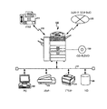
図1の画像処理システムにおいて、100は、画像処理装置であり、101は、LANであり、102は、パーソナルコンピューター(PC)であり、103は、スキャナーであり、104は、プリンターであり、105はハードディスク(HD)である。また、110は、電話回線であり、111は、ファクシミリ装置であり、120は、ネットワーク(インターネット)であり、130は、CD−R、DVDに代表される着脱可能な記録媒体およびその読取/書込装置である。 In the image processing system of FIG. 1, 100 is an image processing apparatus, 101 is a LAN, 102 is a personal computer (PC), 103 is a scanner, 104 is a printer, 105 Is a hard disk (HD). Also, 110 is a telephone line, 111 is a facsimile machine, 120 is a network (Internet), 130 is a removable recording medium represented by CD-R and DVD, and its reading / writing. Device.
ここで、画像処理装置100であるディジタル複合機は、装置本体に原稿読取(スキャナー)機能、画像形成(プリンター)機能および大容量のデータ記憶部を備えているとともに、LAN101を介して、PC102、スキャナー103、プリンター104、HD105と接続されている。
Here, the digital multi-function peripheral that is the
また、画像処理装置100であるディジタル複合機は、電話回線110を介して他のファクシミリ装置111と接続可能であり、電話回線110で他のファクシミリ装置111と画像データを送受信することができる。さらに、インターネットに代表されるネットワーク120と接続可能であり、ネットワーク120から画像データを受信することができるとともに、ネットワーク120へ画像データを送信することもできる。
In addition, the digital multi-function peripheral that is the
また、画像処理装置100であるディジタル複合機は、CD−R、DVDと接続可能であり、CD−R、DVDに記憶された画像データの処理をすることができるとともに、画像データをCD−R、DVDに記憶することもできる。
Further, the digital multi-function peripheral which is the
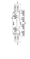
(画像処理装置のハードウエア構成)
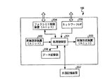
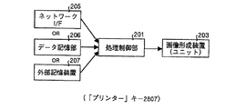
つぎに、画像処理装置100であるディジタル複合機のハードウエア構成について説明する。図2は、実施の形態1にかかる画像処理装置のハードウエア構成の一例を示すブロック図である。図2において、201は、処理制御部であり、202は、原稿読取装置(ユニット)であり、203は、画像形成装置(ユニット)であり、204は、ファクシミリ制御装置(ユニット)であり、205は、ネットワークI/Fであり、206は、データ記憶部であり、画像処理装置100は、上記各構成部を備えている。また、207は、画像処理装置に接続された外部記憶装置である。
(Hardware configuration of image processing device)
Next, a hardware configuration of a digital multi-function peripheral that is the
処理制御部201は、後述する第1選択部601によって選択された入力部603により入力された画像データを第2選択部602によって選択された出力部604により出力するよう、入力部603および出力部604を制御する。入力部603としては、原稿読取装置202、データ記憶部206、外部記憶装置207、さらには、ファクシミリ制御装置(ユニット)204、ネットワークI/F205などが挙げられる。また、出力部604としては、画像形成装置(ユニット)203、データ記憶部206、外部記憶装置207、ファクシミリ制御装置(ユニット)204、ネットワークI/F205などが挙げられる。
The
図3は、実施の形態1にかかる画像処理装置100の原稿読取装置(ユニット)202のハードウエア構成の一例を示すブロック図である。原稿読取装置(ユニット)202によりおこなわれる処理としては以下のようなものがある。
FIG. 3 is a block diagram illustrating an example of a hardware configuration of the document reading device (unit) 202 of the
たとえば、
(1)光学系による原稿反射光の読み取り処理、
(2)CCD(Charge Coupled Device:電荷結合素子)での電気信号への変換処理、
(3)A/D変換器でのディジタル化処理、
(4)シェーディング補正処理(光源の照度分布ムラを補正する処理)、
(5)スキャナーγ補正処理(読み取り系の濃度特性を補正する処理)、
などである。
For example,
(1) Document reflected light reading process by optical system,
(2) Conversion processing into an electric signal in a CCD (Charge Coupled Device).
(3) Digitization processing by A / D converter,
(4) Shading correction processing (processing for correcting illuminance distribution unevenness of the light source),
(5) Scanner γ correction processing (processing for correcting the density characteristics of the reading system),
Etc.
原稿読取装置(ユニット)202は、読取ユニット301と、センサー・ボード・ユニット302とから構成される。原稿を光学的に読み取る読取ユニット301は、図示を省略するランプとミラーとレンズから構成され、原稿に対するランプ照射の反射光をミラーおよびレンズにより受光素子に集光する。
The document reading device (unit) 202 includes a
受光素子、たとえばCCDは、センサー・ボード・ユニット302に搭載され、CCDにおいて電気信号に変換された画像データはディジタル信号に変換された後、センサー・ボード・ユニット302から出力(送信)される。センサー・ボード・ユニット302から出力(送信)された画像データは処理制御部へ送られる。また、センサー・ボード・ユニット302において光学系およびディジタル信号への量子化にともなう信号劣化(スキャナー系の信号劣化とする)を補正する。
A light receiving element, for example, a CCD is mounted on the
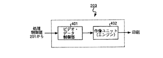
また、図4は、実施の形態1にかかる画像処理装置100の画像形成装置(ユニット)203のハードウエア構成の一例を示すブロック図である。画像形成装置(ユニット)203によりおこなわれる処理としては以下のようなものがある。
FIG. 4 is a block diagram illustrating an example of a hardware configuration of the image forming apparatus (unit) 203 of the
たとえば、
(1)エッジ平滑処理(ジャギー補正処理)、
(2)ドット再配置のための補正処理、
(3)画像信号のパルス制御処理、
などである。
For example,
(1) Edge smoothing process (jaggy correction process),
(2) Correction processing for dot rearrangement,
(3) Image signal pulse control processing,
Etc.
画像形成装置(ユニット)203は、ビデオ・データ制御部401と、作像ユニット(エンジン)402とから構成される。ビデオ・データ制御部401は、入力される画像データに対して、作像ユニット402の特性に応じて、追加の処理をおこなう。
The image forming apparatus (unit) 203 includes a video /
すなわち、面積階調に変化された信号に対して、エッジ平滑処理によるドットの再配置処理をおこない、ドット形成のための画像信号のパルス制御をおこない、上記の処理がおこなわれた画像データを作像ユニット402へ出力する。作像ユニット402においては、ビデオ・データ制御部401から出力された上記画像データを入力し、その画像データに基づいて、転写紙上に再生画像を形成する。
That is, dot rearrangement processing by edge smoothing processing is performed on the signal that has been changed to area gradation, image signal pulse control for dot formation is performed, and image data subjected to the above processing is generated. Output to the
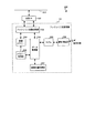
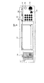
また、図5は、実施の形態1にかかる画像処理装置のファクシミリ制御装置(ユニット)204のハードウエア構成の一例を示すブロック図である。図5のブロック図において、ファクシミリ制御ユニット204は、ファクシミリ送受信部501と外部I/F502とから構成される。ここで、ファクシミリ送受信部501は、画像データを通信形式に変換して外部回線に送信し、また、外部からのデータを画像データに戻して外部I/F502および(パラレル)バス510を介して画像形成装置(ユニット)203によって記録出力する。
FIG. 5 is a block diagram of an example of a hardware configuration of the facsimile control apparatus (unit) 204 of the image processing apparatus according to the first embodiment. In the block diagram of FIG. 5, the
ファクシミリ送受信部501は、ファクシミリ画像処理部503、画像メモリー504、メモリー制御部505、データ制御部506、画像圧縮伸張部507、モデム508および網制御装置509を含む構成である。このうち、ファクシミリ画像処理に関し、受信画像に対する二値スムージング処理は、ビデオ・データ制御部401においておこなう。また、画像メモリー504は、出力バッファー機能を有する。
The facsimile transmission /
このように構成されたファクシミリ送受信部501では、画像データの伝送を開始するときに、データ制御部506がメモリー制御部505に指令し、画像メモリー504から蓄積している画像データを順次読み出させる。読み出された画像データは、ファクシミリ画像処理部503によって元の信号に復元されるとともに、密度変換処理および変倍処理がなされ、データ制御部506に加えられる。
In the facsimile transmission /
データ制御部506に加えられた画像データは、画像圧縮伸張部507によって符号圧縮され、モデム508によって変調された後、網制御装置509を介して宛先へと送出される。そして、送信が完了した画像情報は、画像メモリー504から削除される。
The image data added to the
受信時には、受信画像は一旦画像メモリー504に蓄積され、そのときに受信画像を記録出力可能であれば、1枚分の画像の受信を完了した時点で記録出力する。また、複写動作時に発呼されて受信を開始したときは、画像メモリー504の使用率が所定値、たとえば80%に達するまでは画像メモリー504に蓄積し、画像メモリー504の使用率が80%に達した場合には、そのときに実行している書き込み動作(複写出力動作)を強制的に中断し、受信画像を画像メモリー504から読み出し記録出力する。
At the time of reception, the received image is temporarily stored in the
このとき画像メモリー504から読み出した受信画像は画像メモリー504から削除し、画像メモリー504の使用率が所定値、たとえば10%まで低下した時点で中断していた書き込み動作を再開し、その書き込み動作をすべて終了した時点で、残りの受信画像を記録出力する。また、書き込み動作を中断した後に、再開できるように中断時における書き込み動作のための各種パラメーターを内部的に退避し、再開時に、パラメーターを内部的に復帰する。
At this time, the received image read from the
(画像処理装置の操作部の構成)
つぎに、画像処理装置100の操作部の構成について説明する。図6は、実施の形態1にかかる画像処理装置の操作部の構成を機能的に示すブロック図である。図6のブロック図において、画像処理装置100の操作部は、選択部600および表示部610とから構成される。さらに選択部600は、第1選択部601および第2選択部602を有する。また、表示部610は、第1表示部611、第2表示部612、第3表示部613、第4表示部614を有する。
(Configuration of operation unit of image processing apparatus)
Next, the configuration of the operation unit of the
また、入力部603は、画像データを入力する、それぞれ異なる機能を有する複数の入力部(入力部A、入力部B・・・)からなる。同様に、出力部604は、画像データを出力する、それぞれ異なる機能を有する複数の出力部(出力部A、出力部B・・・)からなる。
The
第1選択部601は、複数の入力部603の中から所望の入力部を選択する。そして、第1表示部611は、後述する表示画面(たとえば、図7に示す表示画面701)を制御して、入力部603が第1選択部によって選択された際に、選択された入力部603の画像データの入力条件を設定する入力条件設定画面を表示する。第1表示部611に表示される入力条件設定画面の内容については後述する。
The
また、第2選択部602は、複数の出力部604の中から所望の出力部を選択する。そして、第2表示部612は、上記表示画面を制御して、出力部604が第2選択部によって選択された際に、選択された出力部604の画像データの出力条件を設定する出力条件設定画面を表示する。第2表示部612に表示される出力条件設定画面の内容についても後述する。
In addition, the
また、第3表示部613は、上記表示画面を制御して、文字、記号、絵等から構成された、各入力部603を示すキー(たとえば、タッチパネルなどをもちいる)を表示する。そして、第1選択部601は、第3表示部613に表示されたキーを押下または接触することにより入力部603を選択するようにしてもよい。第3表示部613に表示される表示画面の内容については後述する。
The
また、第4表示部614は、第3表示部613と同様に、上記表示画面を制御して、文字、記号、絵等から構成された、各出力部604を示すキーを表示する。そして、第2選択部602は、第4表示部614に表示されたキーを押下または接触することにより出力部603を選択するようにしてもよい。第4表示部614に表示される表示画面の内容についても後述する。
Similarly to the
なお、選択部600、表示部610は、それぞれ図示を省略するROM、RAM、ハードディスク、フレキシブルディスク等の記録媒体に記録されたプログラムに記載された命令にしたがってCPUが命令処理を実行することにより、各部の機能を実現する。
The
図7は、実施の形態1にかかる画像処理装置の操作部700の外観の一例を示す説明図である。図7において、操作部700はその中央に操作の状態やメッセージを表示するタッチパネル式の表示画面701を備える。表示画面701は、パネル表面に接触することによりキー入力できるタッチパネルキーと表示用LCDとにより構成される。タッチパネルキーの検出回路および座標検出方法については公知の技術をもちいることにより実現可能であり、その詳細な説明については省略する。
FIG. 7 is an explanatory diagram of an example of the appearance of the operation unit 700 of the image processing apparatus according to the first embodiment. In FIG. 7, the operation unit 700 includes a touch panel
また、表示画面701の左となりの位置には、設定キー群702が配置される。設定キー群702の詳細な内容については後述する。また、表示画面701の右となりの位置には、テンキー/♯キー(エンターキー)703が配置される。また、その右側には、処理開始の指示をするスタートキー704、および入力した数値を取り消したり、処理を中断または中止するためのクリア/ストップキー705が配置される。
A setting
また、テンキー/♯キー703の上側には、リセット/予熱キー706と、割り込みキー707と、割り込みキー707の下側には試しコピーキー708とがそれぞれ配置される。試しコピーは、複数部数コピーするときに最初の一部のコピーで仕上がりを確認するためのものである。また、リセット/予熱キー706の左側には、プログラムキー709が配置される。さらにまた、設定キー群702の上側には、使用条件に合わせて初期設定値や操作条件を変更するための初期設定/カウンターキー710が配置される。
A reset /
(表示画面の内容)
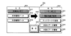
図8〜10は、実施の形態1にかかる画像処理装置の操作部の表示画面に表示される表示内容の一例を示す説明図である。図8は、表示画面の基本表示(初期画面あるいはメニュー画面)の一例を示すものである。この基本表示は後述する設定キー群702の「メニュー」キー2801を押下することによっても表示するようにすることができる。図8において、801は、入力形式を選択するエリア(入力形式選択エリア)であり、802は、出力形式を選択するエリア(出力形式選択エリア)である。
(Contents of display screen)
8 to 10 are explanatory diagrams illustrating examples of display contents displayed on the display screen of the operation unit of the image processing apparatus according to the first embodiment. FIG. 8 shows an example of the basic display (initial screen or menu screen) of the display screen. This basic display can also be displayed by pressing a “menu”
また、矢印800は、画像データの流れ、すなわち、画像データが入力部(入力形式)で入力処理された後、出力部(出力形式)で出力処理されることを示唆することにより、操作者が直感的に入力形式および出力形式を認識することができ、操作者の誤操作を有効に防止することができる。
Further, the
入力形式選択エリア801には、入力部603として入力することが可能な入力形式を表示する。具体的には、入力形式(入力部603)として原稿読取装置(ユニット)202を選択するための「原稿読み取り」キー811と、データ記憶部206を選択するための「本体蓄積データ」キー812と、外部記憶装置207を選択するための「外部蓄積データ」キー813とを表示する。操作者は、所望の入力形式を、各キーが表示されている領域を押下あるいは接触することにより容易に選択することができる。
In the input
出力形式選択エリア802にも同様に、出力部604として入力することが可能な出力形式を表示する。具体的には、出力形式(出力部604)として画像形成装置(ユニット)203を選択するための「印刷」キー821と、ファクシミリ制御装置(ユニット)204を選択するための「電話回線で送信」キー822と、ネットワークI/F205を選択するための「ネットワークで送信」キー823と、データ記憶部206を選択するための「本体にデータ蓄積」キー824と、外部記憶装置207を選択するための「外部にデータ蓄積」キー825とを表示する。
Similarly, an output format that can be input as the
図9は、入力形式として「原稿読み取り」キー811が、出力形式として「印刷」キー821が選択された状態を示す。選択された入力形式を容易に認識させるようにするために、選択されたキーの表示形態を変更するとよい。図9にあっては、「原稿読み取り」キー811および「印刷」キー821の表示領域を反転表示させるようにしたが、操作者に認識させる用にするための表示形態であれば、反転表示に限らない。たとえば、カラーの表示装置であれば、表示色を変更させたり、また、操作者により明確に認識させるために点滅表示にしたりするようにしてもよい。
FIG. 9 shows a state in which the “original reading” key 811 is selected as the input format and the “print”
また、入力形式および出力形式の選択が完了すると、図9に示すように、表示画面701の中央下側に「実行」キー901を表示する。操作者は、「実行」キー901を押下(接触)する前であれば、入力形式および出力形式の選択を変更することができる。すなわち、操作者は変更したいキーを押下(接触)することにより容易に変更できる。変更された場合には、変更されたキーの表示形態を変更し(反転表示し)、変更前に選択されていたキーの表示形態は元の状態に戻す。
When the selection of the input format and the output format is completed, an “execute” key 901 is displayed at the lower center of the
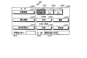
「実行」キー901が押下されたことを検知して、表示画面を切り替えることにより図10に示す内容に変更する。図10に示すように、入力形式選択エリア801が表示されていた領域に入力条件設定エリア1001を、出力形式選択エリア802および「実行」キー901が表示されていた領域に出力条件設定エリア1002を、それぞれ表示する。
By detecting that the “execute” key 901 has been pressed, the display screen is switched to change to the content shown in FIG. As shown in FIG. 10, the input
入力条件設定エリア1001は、選択された入力形式(入力部603)における画像データの入力条件を設定するものである。したがって、選択された入力形式によって表示される内容が異なる。出力条件設定エリア1002は、選択された出力形式(入力部604)における画像データの出力条件を設定するものである。したがって、選択された出力形式によって表示される内容が異なる。図10に示す入力条件設定エリア1001は、「原稿読み取り」キー811に対応するものであり、出力条件設定エリア1002は、「印刷」キー821に対応するものである。
The input
入力条件設定エリア1001には、原稿の種類を設定するための「原稿種類」キー1011と、原稿の読み取り濃度を調整するための「濃度調整」キー1012と、特殊原稿送りが必要な場合にその設定をするための「特殊原稿送り」キー1013とを表示する。それぞれのキーを押下(接触)することにより、さらに各設定をおこなうための別の設定画面が表示される。それらの設定画面については図示を省略する。
The input
また、入力条件設定エリア1001の下側には、選択された入力形式を表示したタグ(「原稿読み取り」)1010を表示する。これにより、操作者が容易に入力条件を設定しようとしている入力形式を認識することができる。
A tag (“document reading”) 1010 displaying the selected input format is displayed below the input
また、出力条件設定エリア1002には、記録紙のサイズを選択するためのトレイ選択キー1021〜1023と、変倍(拡大、縮小)処理を設定するための「変倍」キー1024と、複数枚の原稿を1枚の用紙の中にコピーするなどの印刷する際の編集を設定するための「編集」キー1025と、両面印刷処理を設定するための「両面」キー1026と、印刷された記録紙のパンチやステープル作業などの後処理を設定するための「後処理」キー1027とを表示する。
The output
また、入力条件設定エリア1001と同様に、出力条件設定エリア1002の下側には、選択された出力形式を表示したタグ(「印刷」)1020を表示する。これにより、操作者が容易に出力条件を設定しようとしている入力形式を認識することができる。
Similarly to the input
上記のようにして、入力形式および出力形式の選択、入力条件の設定および出力条件の設定が終了した後、図7に示したスタートキー704が押下されるのを待って、上記設定された所望の画像処理を開始する。
After the selection of the input format and the output format, the setting of the input condition, and the setting of the output condition as described above, after waiting for the
図11は、実施の形態1にかかる画像処理装置の図8〜図10に示された操作指示に対応した処理の内容を示す説明図である。図8〜図10において、選択された入力形式は「原稿読み取り」であったので、入力部603として、画像読み取り装置(ユニット)202により原稿を読み取り、読み取った画像データを処理制御部201で処理をおこなう。また、出力形式は「印刷」であったので、出力部604として、画像形成装置(ユニット)203により、画像データを印刷する。
FIG. 11 is an explanatory diagram of the contents of processing corresponding to the operation instructions shown in FIGS. 8 to 10 of the image processing apparatus according to the first embodiment. 8 to 10, since the selected input format is “original reading”, the
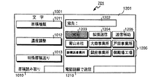
図12は、実施の形態1にかかる画像処理装置の操作部の表示画面701に表示される表示内容の別の一例を示す説明図である。図8に示した基本表示において、入力形式として「原稿読み取り」キー811が、出力形式として「電話回線で送信」キー822が選択された場合に、図12に示す表示画面となる。ここで、入力条件設定エリアは図10に示した入力条件設定エリア1001と同様の内容となる。
FIG. 12 is an explanatory diagram of another example of display content displayed on the
また、入力条件設定エリア1001の下側には、選択された入力形式を表示したタグ(「原稿読み取り」)1010を表示する。これにより、操作者が容易に入力条件を設定しようとしている入力形式を認識することができる。
A tag (“document reading”) 1010 displaying the selected input format is displayed below the input
一方、出力条件設定エリア1201は、図10に示した出力条件設定エリア1002とは異なり、電話回線で送信する際の条件を設定するための表示内容となっている。これは、相手先の設定など、ファクシミリ送信をするために必要な条件を設定することがその主な目的となっている。具体的には、宛先入力欄1202と、「宛先」キー1203と、「拡張送信」キー1204と、「送信補助」キー1205とからなる。
On the other hand, unlike the output
また、「宛先」キー1203、「拡張送信」キー1204、「送信補助」キー1205の下側は、上記各キー1203〜1205の押下によって更なる条件の設定をするための内容を表示する表示領域である。図12にあっては、「宛先」キー1203が選択されているため、宛先を設定するための内容1206が表示されている。その内容は、あらかじめ登録された宛先を示す内容(名称)が各キーとなって表示されていることがわかる。
Further, below the “destination” key 1203, the “extended transmission” key 1204, and the “transmission assist” key 1205, a display area for displaying contents for setting further conditions by pressing the
操作者は、表示された内容から所望の宛先(「青山本社」、「大森事業所」、「戸田事業所」、「新横浜事業所」、「銀座事業所」、「御殿場工場」)を選択する。選択の方法は上述と同様に、各宛先が表示されている領域がキーになっているので、そのキーを押下(接触)することによりおこなうことができる。宛先が多く表示しきれない場合は、図示を省略する次ページキーを表示させ、そのキーを押下(接触)することにより、次ページに別の宛先を表示させることができる。 The operator selects a desired destination (“Aoyama head office”, “Omori office”, “Toda office”, “Shin Yokohama office”, “Ginza office”, “Gotemba factory”) from the displayed contents. . As described above, since the area where each destination is displayed is a key, the selection method can be performed by pressing (contacting) the key. When a large number of destinations cannot be displayed, a next page key (not shown) is displayed, and another destination can be displayed on the next page by pressing (contacting) the key.
宛先が選択されると、宛先入力欄1202に選択された宛先名あるいは宛先のファクシミリ番号などが表示される。また、宛先入力欄1202に直接宛先のファクシミリ番号を図7に示したテンキー703をもちいて入力するようにしてもよい。宛先に関する情報があらかじめ登録されていない場合に有効である。
When a destination is selected, the destination name or destination facsimile number is displayed in the
また、「拡張送信」キー1204は、時刻指定など、送信時の拡張機能を設定する際にもちいる。また、「送信補助」キー1205は、自動縮小など、送信時の補助的機能を設定する際にもちいる。 The “extended transmission” key 1204 is used to set an extended function at the time of transmission such as time designation. The “transmission assistance” key 1205 is used to set an auxiliary function at the time of transmission such as automatic reduction.
また、出力条件設定エリア1201の下側には、選択された出力形式を表示したタグ(「電話回線で送信」)1210を表示する。これにより、操作者が容易に出力条件を設定しようとしている出力形式を認識することができる。
Further, a tag (“send via telephone line”) 1210 displaying the selected output format is displayed below the output
図13は、実施の形態1にかかる画像処理装置の図12に示された操作指示に対応した処理の内容を示す説明図である。図13に示すように、図12において選択された入力形式は「原稿読み取り」であったので、入力部603として、画像読み取り装置(ユニット)202により原稿を読み取り、読み取った画像データを処理制御部201で処理をおこなう。また、出力形式は「電話回線で送信」であったので、出力部604として、ファクシミリ制御装置(ユニット)204により、画像データをファクシミリ送信する。
FIG. 13 is an explanatory diagram of processing contents corresponding to the operation instructions shown in FIG. 12 of the image processing apparatus according to the first embodiment. As shown in FIG. 13, since the input format selected in FIG. 12 is “document reading”, the
図14は、実施の形態1にかかる画像処理装置の操作部の表示画面701に表示される表示内容の別の一例を示す説明図である。図8に示した基本表示において、入力形式として「原稿読み取り」キー811が、出力形式として「ネットワークで送信」キー823が選択された場合に、図14に示す表示画面となる。ここで、入力条件設定エリアは図10に示した入力条件設定エリア1001と同様の内容となる。
FIG. 14 is an explanatory diagram of another example of display content displayed on the
一方、出力条件設定エリア1401は、図10に示した出力条件設定エリア1002や、図12に示した出力条件設定エリア1201とは異なり、ネットワークで送信する際の条件を設定するための表示内容となっている。これは、相手先のメールアドレスの設定など、ネットワーク(インターネット)送信をするために必要な条件を設定することがその主な目的となっている。具体的には、宛先のメールアドレス入力欄1402と、「宛先」キー1403と、「送信者」キー1404と、「表題」キー1405とからなる。
On the other hand, the output
また、「宛先」キー1403、「送信者」キー1404、「表題」キー1405の下側は、上記各キー1403〜1405の押下によって更なる条件の設定をするための内容を表示する表示領域である。図14にあっては、「宛先」キー1403が選択されているため、宛先のメールアドレスを設定するための内容1406が表示されている。その内容は、あらかじめ登録された宛先(個人)を示す内容(名前)が各キーとなって表示されていることがわかる。各キーは当該宛先(個人)のアドレスと対応している。
The lower side of the “destination” key 1403, the “sender” key 1404, and the “title” key 1405 is a display area for displaying contents for setting further conditions by pressing the
操作者は、表示された内容から所望の個人名(「橋本」、「石田」、「星村」、「矢野」、「高津」、「森川」)を選択する。選択の方法は上述と同様に、個人名が表示されている領域がキーになっているので、そのキーを押下(接触)することによりおこなうことができる。宛先が多く表示しきれない場合は、図示を省略する次ページキーを表示させ、そのキーを押下(接触)することにより、次ページに別の宛先を表示させることができる。 The operator selects a desired personal name (“Hashimoto”, “Ishida”, “Hoshimura”, “Yano”, “Takatsu”, “Morikawa”) from the displayed contents. As described above, since the area where the personal name is displayed is a key, the selection method can be performed by pressing (contacting) the key. When a large number of destinations cannot be displayed, a next page key (not shown) is displayed, and another destination can be displayed on the next page by pressing (contacting) the key.
宛先のメールアドレスが選択されると、宛先入力欄1402に選択された個人名あるいは宛先のメールアドレスなどが表示される。また、宛先入力欄1202に直接個人のメールアドレスを図7に示したテンキー703などをもちいて入力するようにしてもよい。宛先のメールアドレスに関する情報があらかじめ登録されていない場合に有効である。
When the destination mail address is selected, the selected personal name or the destination mail address is displayed in the destination input field 1402. Alternatively, the personal e-mail address may be directly entered in the
また、出力条件設定エリア1401の下側には、選択された出力形式を表示したタグ(「ネットワークで送信」)1410を表示する。これにより、操作者が容易に出力条件を設定しようとしている出力形式を認識することができる。
Further, a tag (“transmit via network”) 1410 displaying the selected output format is displayed below the output
図15は、実施の形態1にかかる画像処理装置の図14に示された操作指示に対応した処理の内容を示す説明図である。図15に示すように、図14において選択された入力形式は「原稿読み取り」であったので、入力部603として、画像読み取り装置(ユニット)202により原稿を読み取り、読み取った画像データを処理制御部201で処理をおこなう。また、出力形式は「ネットワークで送信」であったので、出力部604として、ネットワークI/F205により、画像データをネットワーク120へ送信する。ネットワーク120を介して、所定のメールアドレスへ画像データが送信される。
FIG. 15 is an explanatory diagram of processing contents corresponding to the operation instruction illustrated in FIG. 14 of the image processing apparatus according to the first embodiment. As shown in FIG. 15, since the input format selected in FIG. 14 is “original reading”, the
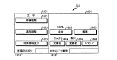
図16は、実施の形態1にかかる画像処理装置の操作部の表示画面701に表示される表示内容の別の一例を示す説明図である。図8に示した基本表示において、入力形式として「原稿読み取り」キー811が、出力形式として「本体にデータ蓄積」キー824が選択された場合に、図16に示す表示画面となる。ここで、入力条件設定エリアは図10に示した入力条件設定エリア1001と同様の内容となる。
FIG. 16 is an explanatory diagram of another example of display content displayed on the
一方、出力条件設定エリア1601は、図10に示した出力条件設定エリア1002や、図12に示した出力条件設定エリア1201や、図14に示した出力条件設定エリア1401とは異なり、画像データをデータ記憶部206に記憶(蓄積)する際の条件を設定するための表示内容となっている。これは、画像データの蓄積するために必要な条件を設定することがその主な目的となっている。具体的には、「変倍」キー1602と、「編集」キー1603と、それらのキーの下側に備えられた、「文書名」キー1604と、「登録者」キー1605と、「パスワード」キー1606とからなる。
On the other hand, the output
「変倍」キー1602は、画像データを蓄積する際に変倍(拡大、縮小)処理をおこなう場合にもちいる。また、「編集」キー1603は、画像データを蓄積する際に必要な編集をおこなう場合にもちいる。また、「文書名」キー1604と、「登録者」キー1605と、「パスワード」キー1606は、蓄積した画像データを検索する際に必要になる情報を併せて登録するためのものである。また、「パスワード」キー1606によって図示を省略するパスワード設定画面をもちいてパスワードを設定することにより、蓄積された画像データの内容を登録者以外に見させないようにすることができる。 The “scaling” key 1602 is used when scaling (enlarging or reducing) processing is performed when storing image data. The “edit” key 1603 is also used to perform editing necessary for storing image data. A “document name” key 1604, a “registrant” key 1605, and a “password” key 1606 are used to register information necessary for searching stored image data. Further, by setting a password by using a password setting screen (not shown) using the “password” key 1606, it is possible to prevent the contents of the stored image data from being viewed by anyone other than the registrant.
また、出力条件設定エリア1601の下側には、選択された出力形式を表示したタグ(「本体にデータ蓄積」)1610を表示する。これにより、操作者が容易に出力条件を設定しようとしている出力形式を認識することができる。
Also, a tag (“data accumulation in main body”) 1610 displaying the selected output format is displayed below the output
図17は、実施の形態1にかかる画像処理装置の図16に示された操作指示に対応した処理の内容を示す説明図である。図16において、選択された入力形式は「原稿読み取り」であったので、入力部603として、画像読み取り装置(ユニット)202により原稿を読み取り、読み取った画像データを処理制御部201で処理をおこなう。また、出力形式は「本体にデータ蓄積」であったので、出力部604として、データ記憶部206により、画像データを所定の検索用データと対応させて記憶する。
FIG. 17 is an explanatory diagram of processing contents corresponding to the operation instructions shown in FIG. 16 of the image processing apparatus according to the first embodiment. In FIG. 16, since the selected input format is “original reading”, the original is read by the image reading apparatus (unit) 202 as the
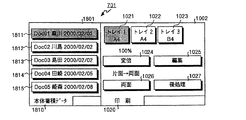
図18は、実施の形態1にかかる画像処理装置の操作部の表示画面701に表示される表示内容の別の一例を示す説明図である。図8に示した基本表示において、入力形式として「本体蓄積データ」キー812が、出力形式として「印刷」キー821が選択された場合に、図18に示す表示画面となる。
FIG. 18 is an explanatory diagram of another example of display contents displayed on the
入力条件設定エリア1801は、データ記憶部206に記憶された画像データの中から画像処理の対象とする所望の画像データを検索する際の検索条件を設定するものである。具体的には、画像データを文書名および登録者名を特定するものである。入力条件設定エリア1801には、蓄積された画像データが、それぞれ、ファイルキー1811,1812,1813,1814,1815,・・・として、「文書名」、「登録者」、「登録日」を表示する。
The input
操作者は、表示されたファイルキーの中から所望の画像データに該当するファイルキーを押下(接触)することで、画像処理の対象とする画像データを特定する。蓄積された画像データ数が多く一度に表示しきれない場合は、図示を省略する次ページキーを表示させ、そのキーを押下(接触)することにより、次ページに別の宛先を表示させることができる。 An operator specifies image data to be subjected to image processing by pressing (contacting) a file key corresponding to desired image data from among the displayed file keys. When the number of stored image data is large and cannot be displayed all at once, a next page key (not shown) is displayed, and by pressing (contacting) the key, another destination can be displayed on the next page. it can.
また、入力条件設定エリア1801の下側には、選択された入力形式を表示したタグ(「本体蓄積データ」)1810を表示する。これにより、操作者が容易に入力条件を設定しようとしている入力形式を認識することができる。
Further, a tag (“main body accumulated data”) 1810 displaying the selected input format is displayed below the input
また、出力条件設定エリアは図10に示した出力条件設定エリア1002と同様の内容となる。上記のようにして、入力形式および出力形式の選択、入力条件の設定および出力条件の設定が終了した後、図7に示したスタートキー704が押下されるのを待って、上記設定された所望の画像処理を開始する。
The output condition setting area has the same contents as the output
図19は、実施の形態1にかかる画像処理装置の図18に示された操作指示に対応した処理の内容を示す説明図である。図18において、選択された入力形式は「本体蓄積データ」であったので、入力部603として、データ記憶部206により原稿を読み取り、読み取った画像データを処理制御部201で処理をおこなう。また、出力形式は「印刷」であったので、出力部604として、画像形成装置(ユニット)203により、画像データを印刷する。
FIG. 19 is an explanatory diagram of processing contents corresponding to the operation instructions shown in FIG. 18 of the image processing apparatus according to the first embodiment. In FIG. 18, since the selected input format is “main body accumulated data”, a document is read by the
(画像処理装置の処理手順)
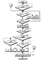
図20は、実施の形態1にかかる画像処理装置の一連の処理の手順を示すフローチャートである。図20のフローチャートにおいて、まず、入力形式・出力形式が選択されたか否かを判断し(ステップS2001)、選択されるのを待って、選択された場合(ステップS2001肯定)は、つぎに、選択された入力形式・出力形式に変更があったか否かを判断する(ステップS2002)。
(Processing procedure of image processing apparatus)
FIG. 20 is a flowchart of a series of processing procedures performed by the image processing apparatus according to the first embodiment. In the flowchart of FIG. 20, first, it is determined whether or not an input format / output format has been selected (step S2001), waits for selection, and if selected (Yes in step S2001), then selects It is determined whether or not the input format / output format has been changed (step S2002).
ステップS2002において、変更があった場合(ステップS2002肯定)は、変更指示にしたがって入力形式・出力形式を変更し(ステップS2003)、ステップS2002へ戻る。一方、ステップS2002において、変更がない場合(ステップS2002否定)は、つぎに、実行キー901が押下(接触)されたか否かを判断する(ステップS2003)。ここで、実行キー901が押下(接触)されない場合(ステップS2004否定)は、ステップS2002へ移行する。
If there is a change in step S2002 (Yes in step S2002), the input format / output format is changed in accordance with the change instruction (step S2003), and the process returns to step S2002. On the other hand, if there is no change in Step S2002 (No in Step S2002), it is next determined whether or not the
一方、ステップS2004において、実行キー901が押下(接触)された場合(ステップS2004肯定)は、つぎに、入力条件設定画面・出力条件設定画面を表示する(ステップS2005)。ここで、入力条件・出力条件が設定されたか否かを判断し(ステップS2006)、設定されるのを待って、設定された場合(ステップS2006肯定)は、ステップS2007へ移行する。
On the other hand, when the
ステップS2007において、入力形式が「本体蓄積データ」あるいは「外部蓄積データ」であるか否かを判断する。ここで、入力形式が「本体蓄積データ」あるいは「外部蓄積データ」でない場合(ステップS2007否定)は、つぎに、読取用原稿が原稿読取装置(ユニット)202の所定の位置にセットされたか否かを判断する(ステップS2008)。ここで、原稿がセットされるのを待って、原稿がセットされた場合(ステップS2008肯定)は、セットされた原稿の読み取り処理をおこなう(ステップS2009)。その後、ステップS2012へ移行する。 In step S2007, it is determined whether the input format is “main body accumulated data” or “external accumulated data”. Here, if the input format is not “main body accumulated data” or “external accumulated data” (No in step S2007), then whether or not the reading document is set at a predetermined position of the document reading device (unit) 202 is determined. Is determined (step S2008). If the original is set after waiting for the original to be set (Yes in step S2008), the set original is read (step S2009). Thereafter, the process proceeds to step S2012.
一方、ステップS2007において、入力形式が「本体蓄積データ」あるいは「外部蓄積データ」である場合(ステップS2007肯定)は、蓄積された画像データの中から所望の画像データが選択されたか否かを判断する(ステップS2010)。ここで、画像データが選択されるのを待って、画像データが選択された場合(ステップS2010肯定)は、選択された画像データを読み出し(ステップS2011)、その後、ステップS2012へ移行する。 On the other hand, when the input format is “main body stored data” or “external stored data” in step S2007 (Yes in step S2007), it is determined whether or not desired image data is selected from the stored image data. (Step S2010). Here, after the image data is selected, if the image data is selected (Yes at Step S2010), the selected image data is read (Step S2011), and then the process proceeds to Step S2012.
ステップS2012において、各入力形式により入力された画像データに対して、何もせずそのままあるいは所定の処理を施した後、選択された出力形式により出力処理をおこなう。これにより、一連の処理を終了する。 In step S2012, image data input in each input format is processed as it is or without being subjected to predetermined processing, and then output processing is performed in the selected output format. As a result, the series of processes is completed.
図21は、本実施の形態1にかかる画像処理装置の一連の処理の別の手順を示すフローチャートである。図21は、ファクシミリ受信あるいはネットワークからのデータの受信があった場合の処理の手順を示すものである。図21のフローチャートにおいて、まず、ファクシミリ受信があったか否かを判断し(ステップS2101)、ファクシミリ受信があった場合(ステップS2101肯定)は、つぎに、受信した画像データをデータ記憶部206に蓄積する(ステップS2102)。これにより、一旦ファクシミリ受信画像をデータを蓄積することで、その後にそのファクシミリ受信画像の出力形式を選択できる。したがって、単に記録紙に出力してしまうのに比べ、ファクシミリ受信画像の利用価値を向上させることができる。 FIG. 21 is a flowchart illustrating another procedure of a series of processes performed by the image processing apparatus according to the first embodiment. FIG. 21 shows a processing procedure when there is a facsimile reception or data reception from a network. In the flowchart of FIG. 21, it is first determined whether or not a facsimile is received (step S2101). (Step S2102). Thus, once the facsimile reception image is stored, the output format of the facsimile reception image can be selected thereafter. Therefore, it is possible to improve the utility value of the received facsimile image as compared with the case where it is simply output to the recording paper.
その後、出力形式が選択されたか否かを判断し(ステップS2103)、出力形式が選択された場合(ステップS2103肯定)は、図20に示したステップS2012(あるいは図26に示した実施の形態2のステップS2615)へ移行する。 Thereafter, it is determined whether or not an output format has been selected (step S2103). If an output format has been selected (Yes in step S2103), step S2012 shown in FIG. 20 (or the second embodiment shown in FIG. 26) is selected. Step S2615).
一方、ステップS2101において、ファクシミリ受信がない場合(ステップS2101否定)は、ネットワーク120からの画像データがあるか否かを判断する(ステップS2104)。ここで、ネットワーク120からの画像データがない場合(ステップS2104否定)は、ステップS2101に戻り、ファクシミリ受信またはネットワークからのデータ受信の待機状態となる。この状態で、図20に示した入力形式・出力形式の選択指示をおこなうこともできる。 On the other hand, if there is no facsimile reception in step S2101 (No in step S2101), it is determined whether there is image data from the network 120 (step S2104). If there is no image data from the network 120 (No at step S2104), the process returns to step S2101 to enter a standby state for facsimile reception or data reception from the network. In this state, an input format / output format selection instruction shown in FIG. 20 can be issued.
一方、ステップS2104において、ネットワーク120からの画像データがあった場合(ステップS2104肯定)は、出力形式が選択されたか否かを判断し(ステップS2105)、出力形式が選択された場合(ステップS2105肯定)は、その画像データを受信し(ステップS2106)、図20に示したステップS2012(あるいは図26に示した実施の形態2のステップS2615)へ移行する。
On the other hand, if there is image data from the
このように、実施の形態1によれば、操作者は、画像データの入力形式と出力形式を別個の選択可能であり、したがって、画像処理に対して所望の画像処理を容易に選択し実行することができる。 As described above, according to the first embodiment, the operator can separately select the input format and the output format of the image data. Therefore, the desired image processing can be easily selected and executed for the image processing. be able to.
〔実施の形態2〕
さて、上述した実施の形態1にあっては、入力形式、出力形式ともそれぞれ一つずつ選択するようにしたが、以下に説明する実施の形態2のように、複数の入力形式、出力形式を一度に選択するようにしてもよい。なお、実施の形態2による画像処理装置を含む画像処理システムのシステム構成、画像処理装置のハードウエア構成、画像処理装置の操作部の構成、画像処理装置の操作部の外観は、実施の形態1と同様であるので、その説明は省略する。
[Embodiment 2]
In the first embodiment, the input format and the output format are selected one by one. However, as in the second embodiment described below, a plurality of input formats and output formats are selected. You may make it select at a time. The system configuration of the image processing system including the image processing apparatus according to the second embodiment, the hardware configuration of the image processing apparatus, the configuration of the operation unit of the image processing apparatus, and the appearance of the operation unit of the image processing apparatus are described in the first embodiment. Since this is the same, the description thereof is omitted.
(表示画面の内容)
図22〜24は、実施の形態2にかかる画像処理装置の操作部の表示画面701に表示される表示内容の一例を示す説明図である。図22は、実施の形態1の図9と同様の表示画面であるが、図9とのちがいは、出力形式として、「印刷」キー821だけでなく、「電話回線で送信」キー822を選択している点である。したがって、「印刷」キー821だけでなく、「電話回線で送信」キー822も反転表示しているのがわかる。
(Contents of display screen)
22 to 24 are explanatory diagrams illustrating examples of display contents displayed on the
この状態で、「実行」キー901が押下されたことを検知して、表示画面701を切り替えることにより図23に示す内容に変更する。図23に示すように、入力形式選択エリア801が表示されていた領域に入力条件設定エリア1001を、出力形式選択エリア802および「実行」キー901が表示されていた領域に出力条件設定エリア1002を、それぞれ表示する。
In this state, it is detected that the “execute” key 901 has been pressed, and the
ただし、図23において、図10に示した出力条件エリア1001との相違点は、タグ(「電話回線で送信」)1210を同時に表示する点である。そして、タグ1210の表示領域が押下(接触)されたことを検知して、図24に示すように、出力条件設定エリア1202を表示する。また、図24に示した状態で、タグ1020の表示領域が押下(接触)されたことを検知して、図23に示す状態に再び戻すことができる。
However, in FIG. 23, the difference from the
このように、操作者は、タグ1020、1210の表示領域を押下(接触)することにより、容易に出力条件設定エリアの表示内容を変更(切り替え)することができる。入力条件設定エリア1001、出力条件設定エリア1002,1201については、図10,図12において説明した内容と同様であるので、それらの説明は省略する。
In this way, the operator can easily change (switch) the display contents of the output condition setting area by pressing (contacting) the display area of the
図25は、実施の形態2にかかる画像処理装置の図22〜24に示された操作指示に対応した処理の内容を示す説明図である。図25において、選択された入力形式は「原稿読み取り」であったので、入力部603として、画像読み取り装置(ユニット)202により原稿を読み取り、読み取った画像データを処理制御部201で処理をおこなう。また、出力形式は「印刷」であったので、出力部604として、画像形成装置(ユニット)203により、画像データを印刷する。さらに、出力形式は「電話回線で送信」であったので、出力部604として、ファクシミリ制御装置(ユニット)204により、画像データをファクシミリ送信もおこなう。
FIG. 25 is an explanatory diagram of processing contents corresponding to the operation instructions shown in FIGS. 22 to 24 of the image processing apparatus according to the second embodiment. In FIG. 25, since the selected input format is “document reading”, the image reading device (unit) 202 reads the document as the
上記の例では、出力形式のみ複数個選択したが、入力形式を複数選択してもよい。また、入力形式・出力形式ともに複数個選択するようにしてもよい。複数個であるから、二つに限定されるものではなく、三つ以上選択するようにしてもよい。 In the above example, only a plurality of output formats are selected, but a plurality of input formats may be selected. A plurality of input formats and output formats may be selected. Since there are a plurality, the number is not limited to two, and three or more may be selected.
(画像処理装置の処理手順)
図26は、実施の形態2にかかる画像処理装置の一連の処理の手順を示すフローチャートである。図26のフローチャートにおいて、まず、入力形式・出力形式が選択されたか否かを判断し(ステップS2601)、選択されるのを待って、選択された場合(ステップS2601肯定)は、つぎに、すべての入力形式・出力形式の選択が終了したか否かを判断する(ステップS2602)。具体的には、操作者はすべての入力形式・出力形式の選択を終了した時点で、「実行」キー901を押下する。その押下を検知することで、すべての入力形式・出力形式の選択が終了したか否かを判断する。
(Processing procedure of image processing apparatus)
FIG. 26 is a flowchart of a series of processing procedures of the image processing apparatus according to the second embodiment. In the flowchart of FIG. 26, first, it is determined whether or not an input format / output format has been selected (step S2601), waits for selection, and if selected (Yes in step S2601), then all It is determined whether or not selection of the input format / output format has been completed (step S2602). Specifically, the operator presses the “execute” key 901 when selection of all input formats and output formats is completed. By detecting the pressing, it is determined whether or not selection of all input formats / output formats has been completed.
ステップS2602において、すべての選択が終了していない場合(ステップS2602否定)は、ステップS2601へ移行する。一方、ステップS2602において、すべての選択が終了した場合(ステップS2602肯定)は、選択された入力形式・出力形式に変更があったか否かを判断する(ステップS2603)。 In step S2602, when all selections are not completed (No in step S2602), the process proceeds to step S2601. On the other hand, if all selections are completed in step S2602 (Yes in step S2602), it is determined whether or not the selected input format / output format has been changed (step S2603).
ステップS2603において、変更があった場合(ステップS2603肯定)は、変更指示にしたがって入力形式・出力形式を変更し(ステップS2604)、ステップS2603へ戻る。一方、ステップS2603において、変更がない場合(ステップS2603否定)は、つぎに、実行キー901が押下(接触)されたか否かを判断する(ステップS2605)。ここで、実行キー901が押下(接触)されない場合(ステップS2605否定)は、ステップS2603へ移行する。
If there is a change in step S2603 (Yes in step S2603), the input format / output format is changed in accordance with the change instruction (step S2604), and the process returns to step S2603. On the other hand, if there is no change in Step S2603 (No in Step S2603), it is next determined whether or not the
一方、ステップS2605において、実行キー901が押下(接触)された場合(ステップS2605肯定)は、つぎに、入力条件設定画面・出力条件設定画面を表示する(ステップS2606)。ここで、入力条件・出力条件が設定され、すべての設定が終了したか否かを判断し(ステップS2607)、設定されるのを待って、すべての設定が終了した場合(ステップS2607肯定)は、ステップS2608へ移行する。
On the other hand, if the
ステップS2608において、入力形式が「本体蓄積データ」あるいは「外部蓄積データ」であるか否かを判断する。ここで、入力形式が「本体蓄積データ」あるいは「外部蓄積データ」でない場合(ステップS2608否定)は、つぎに、読取用原稿が原稿読取装置(ユニット)202の所定の位置にセットされたか否かを判断する(ステップS2609)。ここで、原稿がセットされるのを待って、原稿がセットされた場合(ステップS2609肯定)は、セットされた原稿の読み取り処理をおこなう(ステップS2610)。そして、ステップS2613へ移行する。 In step S2608, it is determined whether the input format is “main body accumulated data” or “external accumulated data”. If the input format is not “main body accumulated data” or “external accumulated data” (No in step S2608), whether or not the reading document is set at a predetermined position of the document reading device (unit) 202 is checked next. Is determined (step S2609). If the original is set after waiting for the original to be set (step S2609 affirmative), the set original is read (step S2610). Then, control goes to a step S2613.
一方、ステップS2608において、入力形式が「本体蓄積データ」あるいは「外部蓄積データ」である場合(ステップS2608肯定)は、蓄積された画像データの中から所望の画像データが選択されたか否かを判断する(ステップS2611)。ここで、画像データが選択されるのを待って、画像データが選択された場合(ステップS2611肯定)は、選択された画像データを読み出し(ステップS2612)、その後、ステップS2613へ移行する。 On the other hand, if the input format is “main body accumulated data” or “external accumulated data” in step S2608 (Yes in step S2608), it is determined whether or not desired image data has been selected from the accumulated image data. (Step S2611). Here, after the image data is selected, if the image data is selected (Yes at step S2611), the selected image data is read (step S2612), and then the process proceeds to step S2613.
ステップS2613において、選択された入力形式によるすべての入力処理が終了したか否かを判断する。ここで、すべて終了していない場合(ステップS2613否定)は、ステップS2608へ移行する。そして、ステップS2608〜ステップS2613までの各ステップをすべて終了するまで繰り返しおこなう。 In step S2613, it is determined whether all input processes using the selected input format have been completed. Here, if all of them have not been completed (No at Step S2613), the process proceeds to Step S2608. The steps from step S2608 to step S2613 are repeated until all the steps are completed.
ステップS2613において、すべて終了した場合(ステップS2613肯定)は、各入力形式により入力された画像データに対して、何もせずそのままあるいは所定の処理を施した後、選択された出力形式により出力処理をおこなう(ステップS2614)。そして、選択された出力形式によるすべての出力処理が終了したか否かを判断する(ステップS2615)。 In step S2613, when all the processes are completed (Yes in step S2613), the image data input in each input format is processed as it is or without performing a predetermined process, and then the output process is performed in the selected output format. Perform (step S2614). Then, it is determined whether or not all the output processes using the selected output format have been completed (step S2615).
ステップS2615において、すべて終了していない場合(ステップS2615否定)は、ステップS2614へ移行する。そして、ステップS2614、S2615の各ステップをすべて終了するまで繰り返しおこなう。ステップS2615において、すべての出力処理が終了した場合(ステップS2615肯定)は、これにより、一連の処理を終了する。 In step S2615, when all the processes have not been completed (No in step S2615), the process proceeds to step S2614. The steps S2614 and S2615 are repeated until all steps are completed. In step S2615, when all the output processes are completed (Yes in step S2615), the series of processes is thereby terminated.
以上説明したように、実施の形態2によれば、一度の操作で、複数の画像データを異なる入力部603から入力し、その入力したデータを出力することができる。また、入力部603により入力されたデータを、一度の操作で複数の出力部604によりそれぞれ出力することができる。
As described above, according to the second embodiment, it is possible to input a plurality of image data from
〔実施の形態3〕
さて、上述した実施の形態1または2にあっては、入力形式および出力形式を別個の操作により選択するようにしたが、以下に説明する実施の形態3のように、複数の入力形式と出力形式の組み合わせをあらかじめ定めて、その組み合わせを指定することにより入力形式および出力形式を一度の操作で選択するようにしてもよい。なお、実施の形態3による画像処理装置を含む画像処理システムのシステム構成、画像処理装置のハードウエア構成、画像処理装置の操作部の外観は、実施の形態1または2と同様であるので、その説明は省略する。
[Embodiment 3]
In the first or second embodiment, the input format and the output format are selected by separate operations. However, as in the third embodiment described below, a plurality of input formats and outputs are selected. A combination of formats may be determined in advance, and an input format and an output format may be selected by a single operation by designating the combination. The system configuration of the image processing system including the image processing apparatus according to the third embodiment, the hardware configuration of the image processing apparatus, and the appearance of the operation unit of the image processing apparatus are the same as those in the first or second embodiment. Description is omitted.
(画像処理装置の操作部の構成)
図27は、実施の形態3にかかる画像処理装置の操作部の構成を機能的に示すブロック図である。図27において、図6に示した実施の形態1にかかる画像処理装置の操作部の構成と異なる点は、組合せ情報記憶部2701および第3選択部2702をさらに加えた点である。なお、図6と同一の構成部については同一の符号を付してその説明を省略する。
(Configuration of operation unit of image processing apparatus)
FIG. 27 is a block diagram functionally illustrating the configuration of the operation unit of the image processing apparatus according to the third embodiment. 27 differs from the configuration of the operation unit of the image processing apparatus according to the first embodiment shown in FIG. 6 in that a combination
組合せ情報記憶部2701は、第1選択部601により選択された入力部603と、第2選択部により選択された出力部604との組み合わせに関する情報を記憶する。組合せ情報記憶部2701は、図示を省略するRAM、ハードディスクなどの記録媒体およびその記憶媒体を読み出したり書き込んだりする読み出し/書き込み装置などによりその機能を実現する。
The combination
また、選択部600は、さらに第3選択部2702を有し、第3選択部2702は、組合せ情報記憶部2701により記憶された組み合わせに関する情報の中から所望の組み合わせを選択する。その際、図2に示した処理制御部201が、第3選択部2702によって選択された入力部603および出力部604を制御して、入力部603により入力された画像データを、出力部604により出力する。なお、第3選択部2702をもちいた具体的な選択方法については後述する。
The
(表示画面の内容)
図28〜30は、実施の形態3にかかる画像処理装置の操作部の一部および表示画面701に表示される表示内容の一例を示す説明図である。図28〜30において、表示画面701の左側には、設定キー群702が設けられている。設定キー群702は、上から「メニュー」キー2801、「コピー」キー2802、「ファクシミリ」キー2803、「スキャナー」キー2804、「ユーザー設定1」キー2805、「ユーザー設定2」キー2806、「プリンター」キー2807が設けられている。
(Contents of display screen)
FIGS. 28 to 30 are explanatory diagrams illustrating an example of display contents displayed on a part of the operation unit and the
また、図示は省略する(図7においては記載した)が、各キー2801〜2807の近傍(たとえば左側)に、LEDを設け、各キーが選択されたことによりそのキーに対応するLEDを点灯させるようにしてもよい。これにより、どのキーが選択されたかを操作者が容易に知ることができる。さらにLEDはキーの近傍に設ける代わりにキートップに設けるようにしても同様の効果が得られる。 Although not shown (described in FIG. 7), an LED is provided in the vicinity (for example, the left side) of each key 2801 to 2807, and the LED corresponding to the key is turned on when each key is selected. You may do it. As a result, the operator can easily know which key has been selected. Further, the same effect can be obtained if the LED is provided on the key top instead of being provided near the key.
さらにまた、LEDを使う代わりに、他の方法によりキートップの状態を変化させることで当該キーが選択されたことを操作者に容易に認知させるような構成であってもよい。以下、図29および図30においても同様の構成とすることができる。 Furthermore, instead of using the LED, the configuration may be such that the operator can easily recognize that the key has been selected by changing the state of the key top by another method. Hereinafter, the same configuration can be used in FIGS. 29 and 30.
これらの設定キー群702は、表示画面701とは別個に設けてある。これにより、より容易にかつ効率的に入力形式と出力形式の組合せにかかる選択をおこなうことができる。したがって、これらの設定キー群702の全部または一部を表示画面701にタッチパネル式に表示させるようにしてもよい。
These setting
「メニュー」キー2801が押下されたことを検知すると、図28に示すように、表示画面701上に図8と同様の基本画面を表示する。また、「コピー」キー2802が押下されると、図29に示した状態になる。すなわち、「コピー」キー2802には、入力形式として「原稿読み取り」キー811が、また、出力形式として「印刷」キー821が組み合わせてとしてあらかじめ登録されており、その登録された組合せによって、入力形式・出力形式が選択された状態になる。
When it is detected that the “menu” key 2801 has been pressed, a basic screen similar to FIG. 8 is displayed on the
その後は、実施の形態1または2に示した内容と同様である。すなわち、図29において、「実行」キー901が押下されたことを検知し、図30に示すように、表示画面701に入力条件設定エリア1001および出力条件設定エリア1002を表示する。また、「コピー」キー2802が押下された場合には、図29を表示することなく、直接に図30に示した表示画面を表示するようにしてもよい。
Thereafter, the contents are the same as those described in the first or second embodiment. That is, in FIG. 29, it is detected that the “execute” key 901 has been pressed, and an input
図31は、実施の形態3にかかる画像処理装置の操作指示(コピー機能)に対応した処理の内容を示す説明図である。図31において、選択された入力形式は「原稿読み取り」であったので、入力部603として、画像読み取り装置(ユニット)202により原稿を読み取り、読み取った画像データを処理制御部201で処理をおこなう。また、出力形式は「印刷」であったので、出力部604として、画像形成装置(ユニット)203により、画像データを印刷する。これにより、コピー機能を実現することができる。
FIG. 31 is an explanatory diagram of processing contents corresponding to an operation instruction (copy function) of the image processing apparatus according to the third embodiment. In FIG. 31, since the selected input format is “original reading”, an original is read by the image reading apparatus (unit) 202 as the
つぎに、「ファクシミリ」キー2803が押下された場合の処理について説明する。図32は、実施の形態3にかかる画像処理装置の別の操作指示(ファクシミリ機能)に対応した処理の内容を示す説明図である。この場合、選択された入力形式は「原稿読み取り」であるので、入力部603として、画像読み取り装置(ユニット)202により原稿を読み取り、読み取った画像データを処理制御部201で処理をおこなう。
Next, processing when the “facsimile” key 2803 is pressed will be described. FIG. 32 is an explanatory diagram of processing contents corresponding to another operation instruction (facsimile function) of the image processing apparatus according to the third embodiment. In this case, since the selected input format is “original reading”, an original is read by the image reading apparatus (unit) 202 as the
また、出力形式は「電話回線で送信」であるので、出力部604として、ファクシミリ制御装置(ユニット)204により、画像データをファクシミリ送信する。これにより、ファクシミリ機能を実現することができる。
Since the output format is “send via telephone line”, the facsimile control apparatus (unit) 204 transmits the image data by facsimile as the
つぎに、「スキャナー」キー2804が押下された場合の処理について説明する。図33は、実施の形態3にかかる画像処理装置の別の操作指示(スキャナー機能)に対応した処理の内容を示す説明図である。この場合、選択された入力形式は「原稿読み取り」であるので、入力部603として、画像読み取り装置(ユニット)202により原稿を読み取り、読み取った画像データを処理制御部201で処理をおこなう。
Next, processing when the “scanner” key 2804 is pressed will be described. FIG. 33 is an explanatory diagram of processing contents corresponding to another operation instruction (scanner function) of the image processing apparatus according to the third embodiment. In this case, since the selected input format is “original reading”, an original is read by the image reading apparatus (unit) 202 as the
また、出力形式は、「本体にデータ蓄積」あるいは「外部にデータ蓄積」のいずれかを選択することができ、それに対応して、データ記憶部206または外部記憶装置107により画像データを記憶(蓄積)する。これにより、スキャナー機能を実現することができる。
As the output format, either “data storage in the main body” or “data storage outside” can be selected, and correspondingly, image data is stored (accumulated) by the
つぎに、「プリンター」キー2804が押下された場合の処理について説明する。図34は、実施の形態3にかかる画像処理装置の操作指示(プリンター機能)に対応した処理の内容を示す説明図である。図34に示すように、入力形式としては、ネットワークから受信する場合と、「本体蓄積データ」あるいは「外部蓄積データ」からの入力を受ける場合を選択することができ、それに対応して、入力部603として、ネットワークI/F205、データ記憶部206、外部記憶装置207から画像データの入力をおこなう。
Next, processing when the “printer” key 2804 is pressed will be described. FIG. 34 is an explanatory diagram of processing contents corresponding to an operation instruction (printer function) of the image processing apparatus according to the third embodiment. As shown in FIG. 34, as an input format, it is possible to select a case of receiving from the network and a case of receiving an input from “main body stored data” or “external stored data”. In step S <b> 603, image data is input from the network I /
入力された画像データを処理制御部201で処理する。そして、また、出力形式は「印刷」であったので、出力部604として、画像形成装置(ユニット)203により、画像データを印刷する。これにより、プリンター機能を実現することができる。
The input image data is processed by the
(画像処理装置の処理手順)
つぎに、入力形式および出力形式の組み合わせを登録する手順について説明する。図35は、実施の形態3にかかる画像処理装置の一連の処理の手順を示すフローチャートである。図35のフローチャートにおいて、まず、入力形式・出力形式が選択されたか否かを判断し(ステップS3501)、選択されるのを待って、選択された場合(ステップS3501肯定)は、つぎに、すべての入力形式・出力形式の選択が終了したか否かを判断する(ステップS3502)。具体的には、操作者はすべての入力形式・出力形式の選択を終了した時点で、「実行」キー901を押下する。その押下を検知することで、すべての入力形式・出力形式の選択が終了したか否かを判断する。
(Processing procedure of image processing apparatus)
Next, a procedure for registering a combination of input format and output format will be described. FIG. 35 is a flowchart of a series of processing steps of the image processing apparatus according to the third embodiment. In the flowchart of FIG. 35, first, it is determined whether or not an input format / output format has been selected (step S3501), waits for selection, and if selected (Yes in step S3501), then all It is determined whether or not selection of the input format / output format has been completed (step S3502). Specifically, the operator presses the “execute” key 901 when selection of all input formats and output formats is completed. By detecting the pressing, it is determined whether or not selection of all input formats / output formats has been completed.
ステップS3502において、すべての選択が終了していない場合(ステップS3502否定)は、ステップS3501へ移行する。一方、ステップS3502において、すべての選択が終了した場合(ステップS3502肯定)は、選択された入力形式・出力形式に変更があったか否かを判断する(ステップS3503)。 If all the selections are not completed in step S3502 (No in step S3502), the process proceeds to step S3501. On the other hand, if all selections are completed in step S3502 (Yes in step S3502), it is determined whether or not the selected input format / output format has been changed (step S3503).
ステップS3503において、変更があった場合(ステップS3503肯定)は、変更指示にしたがって入力形式・出力形式を変更し(ステップS3504)、ステップS3503へ戻る。一方、ステップS3503において、変更がない場合(ステップS3503否定)は、つぎに、設定キー群702の中から設定キー(「ユーザー設定1」2805または「ユーザー設定2」2806)が指定されたか否かを判断する(ステップS3505)。ここで、設定キーが指定されない場合(ステップS3505否定)は、ステップS3503へ移行する。
If there is a change in step S3503 (Yes in step S3503), the input format / output format is changed in accordance with the change instruction (step S3504), and the process returns to step S3503. On the other hand, if there is no change in step S3503 (No in step S3503), whether or not a setting key (“user setting 1” 2805 or “user setting 2” 2806) is designated from the setting
一方、ステップS3505において、設定キーが指定された場合(ステップS3505肯定)は、つぎに、指定された設定キーにすでに別の組み合わせが登録済みであるか否かを判断する(ステップS3506)。ここで、登録済みでなければ(ステップS3506否定)は、ステップS3509へ移行する。 On the other hand, if a setting key is designated in step S3505 (Yes in step S3505), it is next determined whether another combination has already been registered in the designated setting key (step S3506). Here, if not registered (No in step S3506), the process proceeds to step S3509.
ステップS3506において、すでに登録済みの場合(ステップS3506肯定)は、図示を省略するダイアログを表示し、すでに登録済みであることを操作者に知らせるとともに、すでに登録済みの組み合わせに関する情報に新たに登録する情報を上書き可能かどうかの指示を待つ(ステップS3507)。ここで、上書きOKでない場合(ステップS3507否定)は、ステップS3505へ移行し、設定キーの指定をやり直す。 In step S3506, if already registered (step S3506 affirmative), a dialog not shown is displayed to notify the operator that registration has already been performed and to newly register information related to the already registered combination. It waits for an instruction whether information can be overwritten (step S3507). If overwriting is not OK (No at step S3507), the process proceeds to step S3505 and the setting key is designated again.
ステップS3507において、上書きOKの場合(ステップS3507肯定)は、上記登録済みデータを削除し(ステップS3508)、その後、設定キーの登録処理をおこなう(ステップS3509)。そして、すべての処理を終了する。また、設定キー群702をタッチパネル方式とする場合は、キーの名称を登録し、その名称を表示するようにすることもできる。
In the case of overwriting OK in step S3507 (Yes in step S3507), the registered data is deleted (step S3508), and then a setting key registration process is performed (step S3509). Then, all the processes are finished. Further, when the setting
つぎに、第3選択部2702による組み合わせの選択処理について説明する。図36は、実施の形態3にかかる画像処理装置の一連の処理の別の手順を示すフローチャートである。図36のフローチャートにおいて、まず、設定キーが押下されたか否かを判断する(ステップS3601)。ここで、設定キーが押下されるのを待って、押下された場合(ステップS3601肯定)は、押下された設定キーに対応して記憶された組み合わせ情報を組合せ情報記憶部2701の中から検索する(ステップS3602)。
Next, combination selection processing by the third selection unit 2702 will be described. FIG. 36 is a flowchart of another procedure of a series of processes performed by the image processing apparatus according to the third embodiment. In the flowchart of FIG. 36, first, it is determined whether or not the setting key has been pressed (step S3601). Here, after the setting key is pressed, if it is pressed (Yes at step S3601), the combination information stored in correspondence with the pressed setting key is searched from the combination
つぎに、検索された結果に基づいて、入力形式を特定し(ステップS3603)、さらに、出力形式を特定する(ステップS3604)。そして、特定された入出力形式を図29に示すように表示する(ステップS3605)。その後、図20に示したステップS2002(あるいは図26に示したステップS2603)へ移行する。また、設定キーが押下されたときに直接図30等に示す条件入力画面を表示する場合には、ステップS3604からステップS2005またはステップS2606へ移行するようにすればよい。 Next, based on the retrieved result, an input format is specified (step S3603), and an output format is specified (step S3604). Then, the specified input / output format is displayed as shown in FIG. 29 (step S3605). Thereafter, the process proceeds to step S2002 shown in FIG. 20 (or step S2603 shown in FIG. 26). When the condition input screen shown in FIG. 30 or the like is displayed directly when the setting key is pressed, the process may move from step S3604 to step S2005 or step S2606.
以上説明したように、実施の形態3によれば、頻繁に使用する組み合わせを記憶し、設定キーとして登録することができるので、入力形式および出力形式を一度の操作で選択することができる。 As described above, according to the third embodiment, since frequently used combinations can be stored and registered as setting keys, the input format and the output format can be selected by a single operation.
このように、本発明にかかる画像送信装置は、同一の画像データに基づいて異なった送信手段の宛先に同時に送信する画像送信装置であって、任意の宛先と送信手段の組み合わせを登録する登録手段を有することを特徴とする。また、本発明にかかる画像送信方法は、同一の画像データに基づいて異なった送信手段の宛先に同時に送信する画像送信方法であって、任意の宛先と送信手段の組み合わせを登録する登録工程を有することを特徴とする。 As described above, the image transmission apparatus according to the present invention is an image transmission apparatus that transmits simultaneously to destinations of different transmission means based on the same image data, and a registration means that registers a combination of an arbitrary destination and transmission means It is characterized by having. The image transmission method according to the present invention is an image transmission method for simultaneously transmitting to different transmission means destinations based on the same image data, and includes a registration step of registering a combination of an arbitrary destination and transmission means. It is characterized by that.
なお、本実施の形態で説明した画像処理方法は、あらかじめ用意されたプログラムをパーソナルコンピューターやワークステーション等のコンピュータで実行することにより実現することができる。このプログラムは、ハードディスク、フレキシブルディスク、CD−ROM、MO、DVD等のコンピュータで読み取り可能な記録媒体に記録され、コンピュータによって記録媒体から読み出されることによって実行される。またこのプログラムは、上記記録媒体を介して、インターネット等のネットワークを介して配布することができる。 The image processing method described in the present embodiment can be realized by executing a program prepared in advance on a computer such as a personal computer or a workstation. This program is recorded on a computer-readable recording medium such as a hard disk, a flexible disk, a CD-ROM, an MO, and a DVD, and is executed by being read from the recording medium by the computer. The program can be distributed via the recording medium and a network such as the Internet.
100 画像処理装置
101 LAN
102 パーソナルコンピューター(PC)
103 スキャナー
104 プリンター
105 ハードディスク(HD)
110 電話回線
111 ファクシミリ装置
120 ネットワーク(インターネット)
130 CD−R、DVD
201 処理制御部
202 原稿読取装置(ユニット)
203 画像形成装置(ユニット)
204 ファクシミリ制御装置(ユニット)
205 ネットワークI/F
206 データ記憶部
207 外部記憶装置
301 読取ユニット
302 センサー・ボード・ユニット
401 ビデオ・データ制御部
402 作像ユニット(エンジン)
501 ファクシミリ送受信部
502 外部I/F
503 ファクシミリ画像処理部
504 画像メモリー
505 メモリー制御部
506 データ制御部
507 画像圧縮伸張部
508 モデム
509 網制御装置
510 (パラレル)バス
600 選択部
601 第1選択部
602 第2選択部
603 入力部
604 出力部
610 表示部
611 第1表示部
612 第2表示部
613 第3表示部
614 第4表示部
700 操作部
701 表示画面
702 設定キー群
703 テンキー/♯キー(エンターキー)
704 スタートキー
801 入力形式選択エリア
802 出力形式選択エリア
901 「実行」キー
1001 入力条件設定エリア
1002,1201,1401,1601 出力条件設定エリア
1010,1020,1210,1410,1610,1810 タブ
2801 「メニュー」キー
2802 「コピー」キー
2803 「ファクシミリ」キー
2804 「スキャナー」キー
2805 「ユーザー設定1」キー
2806 「ユーザー設定2」キー
2807 「プリンター」キー
100
102 Personal computer (PC)
110
130 CD-R, DVD
201
203 Image forming apparatus (unit)
204 Facsimile control device (unit)
205 Network I / F
206
501 Facsimile transceiver unit 502 External I / F
503 Facsimile
704 Start key 801 Input
Claims (3)
任意の宛先と送信手段の組み合わせを登録する登録手段を有することを特徴とする画像送信装置。 An image transmission apparatus that transmits simultaneously to destinations of different transmission means based on the same image data,
An image transmission apparatus comprising registration means for registering a combination of an arbitrary destination and transmission means.
任意の宛先と送信手段の組み合わせを登録する登録工程を有することを特徴とする画像送信方法。 An image transmission method for simultaneously transmitting to different destinations based on the same image data,
An image transmission method comprising a registration step of registering a combination of an arbitrary destination and transmission means.
Priority Applications (1)
| Application Number | Priority Date | Filing Date | Title |
|---|---|---|---|
| JP2009231973A JP4754643B2 (en) | 2009-10-05 | 2009-10-05 | Image forming apparatus and recording medium |
Applications Claiming Priority (1)
| Application Number | Priority Date | Filing Date | Title |
|---|---|---|---|
| JP2009231973A JP4754643B2 (en) | 2009-10-05 | 2009-10-05 | Image forming apparatus and recording medium |
Related Parent Applications (1)
| Application Number | Title | Priority Date | Filing Date |
|---|---|---|---|
| JP2007266537A Division JP2008029038A (en) | 2007-10-12 | 2007-10-12 | Image transmitting apparatus, image transmitting method, and computer readable recording medium recording program for making computer execute the method |
Related Child Applications (1)
| Application Number | Title | Priority Date | Filing Date |
|---|---|---|---|
| JP2011097653A Division JP2011160474A (en) | 2011-04-25 | 2011-04-25 | Electronic apparatus and computer-readable recording medium |
Publications (2)
| Publication Number | Publication Date |
|---|---|
| JP2010004575A true JP2010004575A (en) | 2010-01-07 |
| JP4754643B2 JP4754643B2 (en) | 2011-08-24 |
Family
ID=41585813
Family Applications (1)
| Application Number | Title | Priority Date | Filing Date |
|---|---|---|---|
| JP2009231973A Expired - Lifetime JP4754643B2 (en) | 2009-10-05 | 2009-10-05 | Image forming apparatus and recording medium |
Country Status (1)
| Country | Link |
|---|---|
| JP (1) | JP4754643B2 (en) |
Citations (7)
| Publication number | Priority date | Publication date | Assignee | Title |
|---|---|---|---|---|
| JPH03151759A (en) * | 1989-11-09 | 1991-06-27 | Canon Inc | Communication equipment |
| JPH09122116A (en) * | 1995-10-31 | 1997-05-13 | Shimadzu Corp | X-ray radiographing device |
| JPH09233216A (en) * | 1996-02-23 | 1997-09-05 | Ricoh Co Ltd | Multimedia batch communication control system |
| JPH1042068A (en) * | 1996-07-25 | 1998-02-13 | Murata Mach Ltd | Communication terminal equipment |
| JP2000032184A (en) * | 1998-07-09 | 2000-01-28 | Ricoh Co Ltd | Image processor |
| JP2000041038A (en) * | 1998-07-23 | 2000-02-08 | Canon Inc | Data transmission system |
| JP4134148B2 (en) * | 2005-11-07 | 2008-08-13 | 株式会社リコー | Image forming apparatus and recording medium |
-
2009
- 2009-10-05 JP JP2009231973A patent/JP4754643B2/en not_active Expired - Lifetime
Patent Citations (7)
| Publication number | Priority date | Publication date | Assignee | Title |
|---|---|---|---|---|
| JPH03151759A (en) * | 1989-11-09 | 1991-06-27 | Canon Inc | Communication equipment |
| JPH09122116A (en) * | 1995-10-31 | 1997-05-13 | Shimadzu Corp | X-ray radiographing device |
| JPH09233216A (en) * | 1996-02-23 | 1997-09-05 | Ricoh Co Ltd | Multimedia batch communication control system |
| JPH1042068A (en) * | 1996-07-25 | 1998-02-13 | Murata Mach Ltd | Communication terminal equipment |
| JP2000032184A (en) * | 1998-07-09 | 2000-01-28 | Ricoh Co Ltd | Image processor |
| JP2000041038A (en) * | 1998-07-23 | 2000-02-08 | Canon Inc | Data transmission system |
| JP4134148B2 (en) * | 2005-11-07 | 2008-08-13 | 株式会社リコー | Image forming apparatus and recording medium |
Also Published As
| Publication number | Publication date |
|---|---|
| JP4754643B2 (en) | 2011-08-24 |
Similar Documents
| Publication | Publication Date | Title |
|---|---|---|
| JP4612571B2 (en) | Image processing apparatus, image processing method, and image processing program | |
| JPH1032691A (en) | Digital composite device | |
| JP2009033530A (en) | Image forming apparatus | |
| JP3635952B2 (en) | Image input apparatus and control method thereof | |
| JP3785297B2 (en) | Image transmitting apparatus, image transmitting method, and computer-readable recording medium storing program for causing computer to execute the method | |
| EP1519558B1 (en) | Image processing apparatus | |
| JP2008029038A (en) | Image transmitting apparatus, image transmitting method, and computer readable recording medium recording program for making computer execute the method | |
| JP4134148B2 (en) | Image forming apparatus and recording medium | |
| JP4754643B2 (en) | Image forming apparatus and recording medium | |
| JP2005045774A (en) | Image read apparatus, image forming apparatus equipped with the same, and scanner system | |
| JP2011160474A (en) | Electronic apparatus and computer-readable recording medium | |
| JP2009225270A (en) | Image processing apparatus, image processing method, and program for causing computer to execute the method | |
| JP2012161093A (en) | Image transmission apparatus, image transmission system, and computer readable recording medium recording program for making computer execute the method | |
| JP2010074478A (en) | Image processing apparatus | |
| JP2012019549A (en) | Image processing apparatus, image processing system, image processing method, and computer readable recording medium recording program for making computer execute the method | |
| JP3803925B2 (en) | Image reading device | |
| JP6996281B2 (en) | Image processor, job execution method, and computer program | |
| JP2004255760A (en) | Information processor, its control method and program | |
| JP2012105181A (en) | Image forming device | |
| JP2002335355A (en) | Communication terminal | |
| JP2023078221A (en) | Information processing device, information processing method and information processing program | |
| JP2023073401A (en) | Information processing apparatus, information processing method, and information processing program | |
| JP2000307834A (en) | Image forming device | |
| JP2014112777A (en) | Facsimile device and control method of the same, and program | |
| JP3557885B2 (en) | Facsimile apparatus and print control method thereof |
Legal Events
| Date | Code | Title | Description |
|---|---|---|---|
| A621 | Written request for application examination |
Free format text: JAPANESE INTERMEDIATE CODE: A621 Effective date: 20091104 |
|
| A131 | Notification of reasons for refusal |
Free format text: JAPANESE INTERMEDIATE CODE: A131 Effective date: 20100629 |
|
| A521 | Written amendment |
Free format text: JAPANESE INTERMEDIATE CODE: A523 Effective date: 20100830 |
|
| A131 | Notification of reasons for refusal |
Free format text: JAPANESE INTERMEDIATE CODE: A132 Effective date: 20110222 |
|
| A521 | Written amendment |
Free format text: JAPANESE INTERMEDIATE CODE: A523 Effective date: 20110425 |
|
| TRDD | Decision of grant or rejection written | ||
| A01 | Written decision to grant a patent or to grant a registration (utility model) |
Free format text: JAPANESE INTERMEDIATE CODE: A01 Effective date: 20110524 |
|
| A01 | Written decision to grant a patent or to grant a registration (utility model) |
Free format text: JAPANESE INTERMEDIATE CODE: A01 |
|
| A61 | First payment of annual fees (during grant procedure) |
Free format text: JAPANESE INTERMEDIATE CODE: A61 Effective date: 20110525 |
|
| FPAY | Renewal fee payment (event date is renewal date of database) |
Free format text: PAYMENT UNTIL: 20140603 Year of fee payment: 3 |
|
| R150 | Certificate of patent or registration of utility model |
Ref document number: 4754643 Country of ref document: JP Free format text: JAPANESE INTERMEDIATE CODE: R150 Free format text: JAPANESE INTERMEDIATE CODE: R150 |
|
| EXPY | Cancellation because of completion of term |