JP2010004267A - Image forming apparatus, log control method, and program - Google Patents
Image forming apparatus, log control method, and program Download PDFInfo
- Publication number
- JP2010004267A JP2010004267A JP2008160670A JP2008160670A JP2010004267A JP 2010004267 A JP2010004267 A JP 2010004267A JP 2008160670 A JP2008160670 A JP 2008160670A JP 2008160670 A JP2008160670 A JP 2008160670A JP 2010004267 A JP2010004267 A JP 2010004267A
- Authority
- JP
- Japan
- Prior art keywords
- log
- network service
- function
- image forming
- forming apparatus
- Prior art date
- Legal status (The legal status is an assumption and is not a legal conclusion. Google has not performed a legal analysis and makes no representation as to the accuracy of the status listed.)
- Granted
Links
Images


Classifications
-
- H—ELECTRICITY
- H04—ELECTRIC COMMUNICATION TECHNIQUE
- H04N—PICTORIAL COMMUNICATION, e.g. TELEVISION
- H04N1/00—Scanning, transmission or reproduction of documents or the like, e.g. facsimile transmission; Details thereof
- H04N1/00127—Connection or combination of a still picture apparatus with another apparatus, e.g. for storage, processing or transmission of still picture signals or of information associated with a still picture
- H04N1/00344—Connection or combination of a still picture apparatus with another apparatus, e.g. for storage, processing or transmission of still picture signals or of information associated with a still picture with a management, maintenance, service or repair apparatus
-
- H—ELECTRICITY
- H04—ELECTRIC COMMUNICATION TECHNIQUE
- H04N—PICTORIAL COMMUNICATION, e.g. TELEVISION
- H04N1/00—Scanning, transmission or reproduction of documents or the like, e.g. facsimile transmission; Details thereof
- H04N1/00832—Recording use, e.g. counting number of pages copied
-
- H—ELECTRICITY
- H04—ELECTRIC COMMUNICATION TECHNIQUE
- H04N—PICTORIAL COMMUNICATION, e.g. TELEVISION
- H04N2201/00—Indexing scheme relating to scanning, transmission or reproduction of documents or the like, and to details thereof
- H04N2201/0077—Types of the still picture apparatus
- H04N2201/0094—Multifunctional device, i.e. a device capable of all of reading, reproducing, copying, facsimile transception, file transception
-
- H—ELECTRICITY
- H04—ELECTRIC COMMUNICATION TECHNIQUE
- H04N—PICTORIAL COMMUNICATION, e.g. TELEVISION
- H04N2201/00—Indexing scheme relating to scanning, transmission or reproduction of documents or the like, and to details thereof
- H04N2201/32—Circuits or arrangements for control or supervision between transmitter and receiver or between image input and image output device, e.g. between a still-image camera and its memory or between a still-image camera and a printer device
- H04N2201/3201—Display, printing, storage or transmission of additional information, e.g. ID code, date and time or title
- H04N2201/3202—Display, printing, storage or transmission of additional information, e.g. ID code, date and time or title of communication or activity log or report
Abstract
Description
本発明は、画像形成装置、ログ制御方法及びプログラムに関する。 The present invention relates to an image forming apparatus, a log control method, and a program.
近年、財務報告の適正性確保を目的とした日本版SOX法(サーベンス・オックス法)について実施が目前となり、ビジネス活動におけるログ収集(活動履歴の取得)が重要性を増している。このようなログは、以下の目的で利用される。
・説明責任〜監査への対応
・モニタリング〜業務の実施状況の確認と異常の検知
・事故対応〜障害対応からフォレンジック、復旧まで
このうち、「説明責任」とは、ログに活動履歴を明らかにすることで、ビジネス活動が適正なものであったことを説明するという目的である。過去のビジネスの正当性を保証する上で、ログが重要な証拠となるのである。
In recent years, the implementation of the Japanese version of the SOX method (Savens Ox method) aimed at ensuring the appropriateness of financial reporting is imminent, and log collection (acquisition of activity history) in business activities is becoming increasingly important. Such a log is used for the following purposes.
-Accountability-Response to audit-Monitoring-Confirmation of work implementation status and detection of abnormalities-Accident response-From failure response to forensics and recovery Of these, "accountability" is to clarify the activity history in the log The purpose is to explain that the business activities were appropriate. Logs are important evidence for ensuring the legitimacy of past business.
画像形成装置などの機器においてもログは重要なものであり、ビジネス活動におけるログと同様の目的で使用される。特に「説明責任」という点においては、ログは機器が適切に動作していることをユーザーに保証するための証拠となる。特に画像形成装置においてはセキュリティ保証の企画が策定中であり、この企画ではログによるセキュリティ関連機能の動作履歴の記録が必須項目に定められる予定である。 Logs are also important in devices such as image forming apparatuses, and are used for the same purpose as logs in business activities. Especially in terms of “accountability”, the logs provide evidence to assure the user that the device is operating properly. In particular, a security guarantee plan is being formulated for the image forming apparatus. In this plan, recording of the operation history of security-related functions using logs is scheduled to be an essential item.
このようにログ機能は重要な機能であるが、画像形成装置などの組み込み機器においては、ログの記録領域が一定であるため、ログフル(ログ記憶領域が一杯になった状態)の状態が生じ得る。ログフルとなった場合、当然ではあるがその後のログを記録することはできない。ログを記録せずに機能を実行することはセキュリティなどの面から考慮して望ましくないため、機能を実施すべきではなく機能を停止すべきであるとの考え方がある。 As described above, the log function is an important function. However, in an embedded device such as an image forming apparatus, the log recording area is constant, and therefore a log full state (a state where the log storage area is full) may occur. . When the log is full, it is natural that the subsequent log cannot be recorded. Since it is not desirable to execute a function without recording a log from the viewpoint of security or the like, there is an idea that the function should not be executed and the function should be stopped.
特開2006−41764号公報(特許文献1)には、新規のジョブに関するログがログ領域に記憶できず、かつ、削除できるログがない場合は、新規のジョブを停止する技術が開示されている。 Japanese Patent Laid-Open No. 2006-41764 (Patent Document 1) discloses a technique for stopping a new job when a log related to a new job cannot be stored in the log area and there is no log that can be deleted. .
また、ネットワークを介して機能を実現する画像形成装置においても、ネットワークを介して実現した機能の活動履歴をログとして記憶する。このとき、ネットワークを介して実現する機能の停止の方法として、特開2001−263098号公報(特許文献2)には、使用されるプロトコルの受信頻度に基づいて、プロトコルを無効にすることにより機能を停止する技術が開示されている。
しかしながら、上記特許文献1の技術では、ただ機能を一律停止するだけでは、ユーザーの利便性が悪い。また、上記特許文献2の技術を適用し、ログ記憶領域に空きがなくなったとき、受信頻度に基づいてネットワークを介した機能を停止しても、ユーザーにとって、利便性がいいとは言えない。
However, with the technique of the above-mentioned
本発明は、上記問題に鑑みてなされたものであり、ユーザーの利便性を考慮したログの制御を行うことができる画像形成装置、ログ制御方法及びプログラムを提供することを目的とする。 SUMMARY An advantage of some aspects of the invention is that it provides an image forming apparatus, a log control method, and a program that can perform log control in consideration of user convenience.
本発明の一局面の画像形成装置は、各機能を実行し、該機能を実行するネットワークサービスのログを記憶する記憶領域を備える画像形成装置であって、前記ネットワークサービスに対応する機能毎にログをグループ化して管理する管理手段と、前記ネットワークサービスのログを、前記ネットワークサービスに対応する機能毎に前記記憶領域に記録する記録手段と、前記機能毎における前記記憶領域の空き状況に関する記憶状態情報に基づいて、前記管理手段に管理されるグループ毎に前記ネットワークサービスを停止する停止手段とを備える。 An image forming apparatus according to an aspect of the present invention is an image forming apparatus that includes a storage area that executes each function and stores a log of a network service that executes the function, and logs each function corresponding to the network service. Management means for grouping and managing the network service, recording means for recording the network service log in the storage area for each function corresponding to the network service, and storage state information relating to the availability of the storage area for each function And a stop means for stopping the network service for each group managed by the management means.
また、本発明の他の局面の画像形成装置は、他の機能と共に実行する所定機能を含む各機能を実行し、該機能を実行するネットワークサービスのログを記憶する記憶領域を備える画像形成装置であって、前記ネットワークサービスに対応する機能毎にグループ化してログを管理する管理手段と、前記ネットワークサービスのログを、前記ネットワークサービスに対応する機能毎に前記記憶領域に記録する記録手段と、前記所定機能における前記記憶領域の空き状況に関する記憶状態情報に基づいて、前記管理手段に管理されるグループ毎に前記ネットワークサービスを停止する停止手段とを備える。 An image forming apparatus according to another aspect of the present invention is an image forming apparatus including a storage area that executes a function including a predetermined function executed together with another function and stores a log of a network service that executes the function. Management means for managing a log by grouping for each function corresponding to the network service; a recording means for recording the log of the network service in the storage area for each function corresponding to the network service; Stop means for stopping the network service for each group managed by the management means, based on storage state information relating to the availability of the storage area in a predetermined function.
また、本発明の他の局面のログ制御方法は、各機能を実行し、該機能を実行するネットワークサービスのログを記憶する記憶領域と、前記ネットワークサービスに対応する機能毎にログをグループ化して管理する管理手段とを備える画像形成装置におけるログ制御方法であって、前記ネットワークサービスのログを、前記ネットワークサービスに対応する機能毎に前記記憶領域に記録する記録ステップと、前記機能毎における前記記憶領域の空き状況に関する記憶状態情報に基づいて、前記管理手段に管理されるグループ毎に前記ネットワークサービスを停止する停止ステップとを有する。 In addition, the log control method according to another aspect of the present invention executes a function, groups a log for each function corresponding to the network service, and a storage area for storing a log of a network service that executes the function. A log control method in an image forming apparatus comprising a management unit for managing, wherein the network service log is recorded in the storage area for each function corresponding to the network service, and the storage for each function And a stop step of stopping the network service for each group managed by the management means based on storage state information relating to the availability of areas.
本発明によれば、ユーザーの利便性を考慮したログの制御を行うことができる。 According to the present invention, it is possible to perform log control in consideration of user convenience.
以下、本発明の実施例を図面に基づいて説明する。 Embodiments of the present invention will be described below with reference to the drawings.
<画像形成装置のハードウェア構成について>
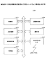
実施例1に係る画像形成装置の主要なハードウェア構成について説明する。図1は、実施例1に係る画像形成装置の主要なハードウェア構成を示す図である。図1に示す画像形成装置100は、制御部101、主記憶部102、補助記憶部103、印字部104、通信制御部105、操作部106、ネットワークI/F107を含む。
<Hardware configuration of image forming apparatus>
A main hardware configuration of the image forming apparatus according to the first embodiment will be described. FIG. 1 is a diagram illustrating a main hardware configuration of the image forming apparatus according to the first embodiment. An
制御部101は、画像形成装置の中で、各装置の制御やデータの演算、加工を行うCPUである。制御部101は、主記憶部102に記憶されたプログラムを実行する演算装置で、入力装置や記憶装置からデータを受け取り、演算、加工した上で、出力装置や記憶装置に出力する。
The
主記憶部102は、ROM(Read Only Memory)やRAM(Random Access Memory)などであり、制御部101が実行する基本ソフトウェアであるOSやアプリケーションソフトウェアなどのプログラムやデータを記憶又は一時保存する記憶装置である。
The
補助記憶部103は、HD(Hard Disk)などであり、アプリケーションソフトウェアなどに関連するデータを記憶する記憶装置である。また、補助記憶部103には、画像処理装置が管理する各種情報(例えば、ユーザ情報など)が格納され、データベース(DB:DataBase)、ファイルシステム(FS:File System)などの機能により管理される。 The auxiliary storage unit 103 is an HD (Hard Disk) or the like, and is a storage device that stores data related to application software and the like. The auxiliary storage unit 103 stores various types of information (for example, user information) managed by the image processing apparatus, and is managed by functions such as a database (DB: DataBase) and a file system (FS: File System). .
印字部104は、画像データを受け取ると、レーザービームを用いたレーザープリントユニットや熱によって専用紙に印字を行なうサーマルプリントユニットなどを用いて、受け取った画像データを転写紙(印刷用紙)に出力(印刷)する。
Upon receiving the image data, the
通信制御部105は、制御部101と連携して、LAN接続やFAXなどの通信制御を行なう。操作部106は、LCD、スイッチ、ランプやLED、キーなどで構成され、画像形成装置の状況、警告などを表示する。
The
ネットワークI/F107は、有線及び/又は無線回線などのデータ伝送路により構築されたLAN(Local Area Network)、WAN(Wide Area Network)、FAXなどのネットワークを介して接続された通信機能を有する周辺機器と画像形成装置などのインタフェースである。
The network I /
<画像形成装置の主要機能構成について>
実施例1に係る画像形成装置の主要機能構成について説明する。図2は、実施例1に係る画像形成装置の主要機能構成を示すブロック図である。図2に示すように、画像形成装置100は、UI部201、アプリケーション部202、ミドルウェア部206、OS部211を含む。
<About main functional configuration of image forming apparatus>
The main functional configuration of the image forming apparatus according to the first embodiment will be described. FIG. 2 is a block diagram illustrating the main functional configuration of the image forming apparatus according to the first embodiment. As illustrated in FIG. 2, the
UI部201は、アプリケーション(例えば、コピー、ファックス、スキャナ、プリント)の実行要求を受け付けるためのUI(User Interface)機能を果たすモジュールである。
The
アプリケーション部202は、プリンタ203、FAX204、コピー205などのアプリケーションを実行するモジュールである。
The
ミドルウェア部206は、ネットワークモジュール207、ログモジュール209、ログ記録部210を含む。ネットワークモジュール207は、各種ネットワークサービスを実現する機能を持ち、アプリケーション部202からの依頼によって、その機能を実施する。
The
また、ネットワークモジュール207は、後述する管理テーブル208を有し、この管理テーブル208には、各ログ記憶領域がログフルの場合、ニヤフルの場合に、どのネットワークサービス、どのネットワークサービスグループを停止するのか、また、停止の際、どのような対応を行うのかの情報が格納されている。
Further, the
ここで、ログフルとは、ログを書き込む記憶領域が全て記憶済みであり、ログが書き込むことができない状態を示し、ニヤフルとは、ログを書き込む記憶領域における記憶済みの割合が所定値以上になった状態を示すことにする。 Here, the log full indicates that the storage area to which the log is written is already stored, and the log cannot be written. The near full indicates that the stored ratio in the storage area to which the log is written is equal to or greater than a predetermined value. Let's show the state.
ログモジュール209は、アプリケーション部202やミドルウェア部206からの依頼によって、ログをログ記録部(ハードディスクなど)210に記録する。ログ記録時はログ記憶領域の残量を確認し、ログフル時とニヤフル時(ニヤフルの基準はユーザーが設定可能)に、その旨を他モジュールに通知する。
The
なお、実施例1ではログフルとニヤフルのみを通知対象とするが、通知対象の選択は任意である。例えば、記憶領域の60%以上をニヤフル1、80%以上をニヤフル2というようにニヤフルを複数に分け、細かいレベルで通知を実施してもよく、細かいレベルで通知を実施したほうが、より柔軟な制御を可能とすることができる。 In the first embodiment, only log full and near full are targeted for notification, but the selection of the notification target is arbitrary. For example, the notification may be performed at a fine level, with 60% or more of the storage area being Nyaful 1 and 80% or more being Nyaful 2, and the notification may be performed at a fine level. Control can be possible.
ログ記録部210は、例えばハードディスクなどであり、ログモジュール209によりログが書き込まれ、書き込まれたログを格納する。OS部211は、画像形成装置自身の制御を行う。
The
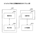
<ミドルウェア部の主要機能構成について>
次に、ミドルウェア部206について詳しく説明する。図3は、ミドルウェア部の主要機能構成を示すブロック図である。図3において、図2に示す構成と同様のものは、図2と同様の符号を付し、その説明を省略する。
<Main function configuration of middleware part>
Next, the
ログモジュール209は、記録手段301を含む。記録手段301は、実行されたネットワークサービスのログを、ネットワークサービスに対応した機能のログ記憶領域に書き込む。このとき、ログモジュール209は、ログの記憶領域の空きを確認し、記憶領域の空き状況を示す記憶状態情報を停止手段303に出力する。なお、ここでは、前述したログフル時とニヤフル時に、その旨を記憶状態情報として停止手段303に出力する。
The
ネットワークモジュール207は、管理手段302、停止手段303を含む。管理手段302は、ネットワークサービスを各アプリケーション(機能)に対応付けて管理テーブル208として保持し、管理テーブル208は、停止手段303に適宜参照される。
The
停止手段303は、記録手段301からログ記録部210の記憶状態情報を取得した場合、管理手段302が管理する管理テーブル208を参照して、どのような処理を行うか判断する。
When acquiring the storage state information of the
図4は、管理テーブルが保持する情報を表すクラス図である。図4に示すように、管理テーブル208は、ネットワークサービス401、ネットワークサービスグループ402、ログ記憶領域403の各情報を関連付けて保持する。
FIG. 4 is a class diagram showing information held in the management table. As shown in FIG. 4, the management table 208 stores information on the
ネットワークサービス401には、サービス名、サービス停止情報、サービス停止時の対応の各情報が格納されている。ここで、サービス名は、ネットワークサービスを識別するための情報であり、サービス停止情報は、ログ記憶領域がどうような状態のときにサービスを停止するかを示す情報である。また、サービス停止時の対応は、サービスを停止する際、どのような処理でサービスを停止するかを示す情報である。サービス停止時の対応には、例えば、待機や無効化などがある。
The
また、ネットワークサービスグループ402には、グループ名の情報が格納されている。さらに、ログ記憶領域403には、領域名、領域容量、使用容量、サービス停止単位1、2の各情報が格納されている。ここで、サービス停止単位とは、サービスを停止する単位を示す情報である。
The
次に、停止手段303が、管理テーブル208に格納される情報を用いてネットワークサービスを停止する処理について説明する。図5は、停止手段の詳細な機能構成を示すブロック図である。
Next, a process in which the stopping
停止手段303は、待機手段501、無効化手段503を含む。まず、停止手段303は、取得した記憶状態情報に基づいて、管理テーブル208の情報を用いてサービスを停止する対象を決定する。
The stopping
停止手段303は、停止する対象を決定した場合、管理テーブル208に格納されている情報に基づいてどのような処理で停止するかを判断する。ここでは、処理を待機する場合は待機手段501により待機処理が行われ、処理を無効化する場合は無効化手段503により無効化処理が行われる。
When the
待機手段501は、届いたパケットに対するアプリケーション部202への機能依頼を止め、パケットが届いたことをネットワークコンポーネントにより一時的にメモリに記憶する。また、待機手段501は、適切なジョブ環境が整ったら機能を実行(ジョブを再開)する。
The waiting
また、待機手段501は、ネットワーク継続手段502を含む。ネットワーク継続手段502は、プロトコルで独自に通信相手とのセッションを維持する必要があるネットワークサービスについては、キープアライブ(定期的にパケットを送信)を行ってセッションを確保し続ける。
The
例えば、PC(パーソナルコンピュータ)から印刷データを受信して印刷する場合に、印刷途中でログがフル状態になり印刷機能を停止する場合、PCにはまだ印刷データが残っているときなどに、機能が再開した後、PCに残っている印刷データを受信するためセッションを確保し続ける必要がある。 For example, when print data is received from a PC (personal computer) and printed, the log becomes full during printing and the print function is stopped. After restarting, it is necessary to keep the session secured in order to receive the print data remaining on the PC.
また、待機手段501を実行する場合には、機能をキャンセルするか管理者を呼んでログを読み出すかの選択をユーザーに行わせるようにしてもよい。ユーザーにより、管理者を呼んでログを読み出すが選択された場合は、ログが読み出されるまでは待機処理を行うことになる。
When executing the waiting
無効化手段503は、ネットワークサービスを無効化するために、ネットワーク通信ポートを閉じたり、ファイヤーウォールで、対象サービスのパケットを止めたりする。なお、機器間のネットワークサービスに対しては無効化手段503を実行し、ユーザー関連(ジョブ関連)のネットワークサービスに対しては待機手段501を実行するようにしてもよい。
The invalidating means 503 closes the network communication port or stops the packet of the target service with a firewall in order to invalidate the network service. Note that the
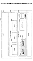
ここで、管理テーブルの具体例と記憶領域との関係について説明する。図6は、実施例1におけるログ記憶領域と管理テーブルとの関係を示す図である。図6に示すように、ログ記録領域は、コピーログ、プリンタログ、管理系ログ、送信系ログ、UI系ログというように各機能に応じて領域が分かれている。 Here, a relationship between a specific example of the management table and the storage area will be described. FIG. 6 is a diagram illustrating the relationship between the log storage area and the management table in the first embodiment. As shown in FIG. 6, the log recording area is divided according to each function such as a copy log, a printer log, a management log, a transmission log, and a UI log.
管理テーブルは、各機能に対応してネットワークサービスをグループ化し、グループ毎にネットワークサービス名、サービス停止情報、サービス停止時の対応の各情報を格納する。例えば、プリント系管理テーブルについて、ネットワークサービス名「TCP/IPraw」、サービス停止情報「2」、サービス停止時の対応「待機」が関連付けられて格納されている。 The management table groups network services corresponding to each function, and stores a network service name, service stop information, and information for handling a service stop for each group. For example, the print system management table stores a network service name “TCP / IPraw”, service stop information “2”, and a response “standby” when the service is stopped.
ここで、「TCP/IPraw」とは、Windows(登録商標)の「標準TCP/IPポート・モニタ」のことを言う。なお、サービス停止情報は、「2」がログフル時に機能停止、「1」がニヤフル時に機能停止を意味する。また、サービス停止情報とサービス停止時の対応とは独立して設定される。 Here, “TCP / IPraw” refers to “standard TCP / IP port monitor” of Windows (registered trademark). In the service stop information, “2” indicates a function stop when the log is full, and “1” indicates a function stop when the log is full. Further, the service stop information and the response at the time of service stop are set independently.
<ログを記録する処理について>
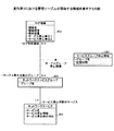
図7は、実施例1に係る画像形成装置におけるログを記録する処理を示すシーケンス図である。ステップ701では、ユーザーが、機能を実行するためUI部201を操作する。ステップ701に続いてステップ702に進み、UI部201が、アプリケーション部203に処理依頼を行う。
<About log recording process>
FIG. 7 is a sequence diagram illustrating processing for recording a log in the image forming apparatus according to the first embodiment. In step 701, the user operates the
ステップ702に続いてステップ703に進み、アプリケーション部202が、依頼された処理を行う。ステップ703に続いてステップ704に進み、アプリケーション部202が、ログモジュール209に対し、ログをログ記録部210に記録するよう記載依頼を行う。
Progressing to step 703 following
ステップ704に続いてステップ705に進み、ログモジュール209が、ログ記載依頼を受けると、ログ記録部210にログを記録する。このとき、ログモジュール209は、記録するログの機能に対応する記憶領域に記録する。ステップ705に続いてステップ706に進み、ログ記録部210は、ログモジュール209により記録されたログを保持する。
Progressing to step 705 following
<ログフルの場合の機能停止処理について>
図8は、実施例1に係る画像形成装置におけるログフル時の機能停止処理を示すシーケンス図である。図8に示す処理において、図7と同様の処理をおこなうものは、図7と同様の符号を付し、その説明を省略する。
<Function stop processing when the log is full>
FIG. 8 is a sequence diagram illustrating a function stop process when the log is full in the image forming apparatus according to the first embodiment. In the processing shown in FIG. 8, the same processing as in FIG. 7 is denoted by the same reference numerals as those in FIG. 7, and description thereof is omitted.
ステップ801では、ログ記録部210が、ログの記憶領域がフルになった(これ以上ログを記録できない)場合、ログフルである旨ログモジュール209に通知する。ステップ801に続いてステップ802に進み、ログモジュール209が、ネットワークモジュール207に、ログフルである旨通知する。
In step 801, the
ステップ802に続いてステップ803に進み、ネットワークモジュール207が、管理テーブル208を読み込む。ステップ803に続いてステップ804に進み、ネットワークモジュール207が、ログフル時の対応として、管理テーブル208のサービス停止時の対応が示す情報に基づいて待機処理又は無効化処理を行う。
In
なお、図8では、ログフル時の処理について説明したが、ステップ801、ステップ802の処理を、ニヤフルを通知に変更し、ステップ804をニヤフル時の対応を行うようにしてもよい。 In FIG. 8, the log full process has been described. However, the process of step 801 and step 802 may be changed from “near full” to “notify”, and step 804 may be dealt with when the log is full.
このようにログフル以外にも、ログの状況に応じた通知を行うことができる。このとき、ネットワークコンポーネントは、それぞれの通知に対して管理テーブルをもとに、通知に対する対応(待機処理又は無効化処理)を決定する。また、管理テーブルにサービス停止対象のネットワークサービスがない場合には、前述した対応を行わない。 As described above, notification according to the status of the log can be performed in addition to the log full. At this time, the network component determines a response (standby process or invalidation process) for each notification based on the management table. Further, when there is no network service to be stopped in the management table, the above-described countermeasure is not performed.
<ログフルの解除処理について>
図9は、実施例1に係る画像処理装置におけるログフルの解除処理を示すシーケンス図である。図9に示す処理によって、ログフルになった記憶領域のログを読み出して記憶領域を空けることで、ログフルのため停止していた機能を再開(解除)することができる。
<About log full release processing>
FIG. 9 is a sequence diagram illustrating the log full release process in the image processing apparatus according to the first embodiment. By reading the log of the storage area where the log is full by the processing shown in FIG. 9 and freeing up the storage area, the function that has been stopped due to the log full can be resumed (released).
ステップ901では、ユーザー(管理者)が、ログを読み出すためUI部201を操作する。ステップ901に続いてステップ902に進み、UI部201が、ログモジュール209に対し、ログの読み出しを指示する。
In
ステップ902に続いてステップ903では、ログモジュール209が、ログ記録部210からユーザー(管理者)に指定されたログを読み出す。ステップ903に続いてステップ904に進み、ログ記録部210が、ログモジュール209に対し、ログフル解除を通知する。
In
ステップ904に続いてステップ905に進み、ログモジュール209が、ネットワークモジュール207に対し、ログフル解除を通知する。ステップ905に続いてステップ906に進み、ネットワークモジュール207が、ログフルのため停止していた機能を再開して、再び機能を実行できるようにする。
Progressing to step 905 following
<実施例1におけるサービス停止処理について>
図10は、実施例1におけるサービス停止処理を示すフローチャートである。ステップ1101では、ネットワークモジュール207の停止手段303が、ログモジュール209から記憶状態情報(ログフル又はニヤフルを示す情報)を取得する。
<About service stop processing in the first embodiment>
FIG. 10 is a flowchart illustrating service stop processing according to the first embodiment. In
ステップ1101に続いてステップ1102に進み、停止手段303は、取得した記憶状態情報の通知先(ログ記憶領域)に対応するサービス停止対象グループがあるか否かを管理テーブルに基づいて判定する。
Progressing to step 1102 following
つまり、停止手段303は、通知されたログ記憶領域に対応するネットワークサービスのグループが、管理テーブルに格納されているか否かを判定する。サービス停止対象グループがあればステップ1103に進み、サービス停止対象グループがなければ処理を終了する。
That is, the stopping
ステップ1103では、停止手段303が、取得した記憶状態情報がログフルを示す情報であるか否かを判定する。ログフルを示す情報である場合はステップ1104に進み、ログフルを示す情報でない場合はステップ1105に進む。
In step 1103, the
ステップ1104では、停止手段303が、取得した記憶状態情報の通知先に対応する管理テーブルに格納される全ネットワークサービスを停止対象とする。例えば、取得した記憶状態情報の通知先がプリンタのログ記憶領域であれば、プリント系管理テーブルに格納されるネットワークサービス全てを停止対象とする。このとき、すでに停止されているネットワークサービスがある場合は、停止対象から除外する。
In
ステップ1105では、停止手段303が、取得した記憶状態情報の通知先に対応する管理テーブルに格納されるネットワークサービスのうち、サービス停止情報がニヤフルを示す「1」であるネットワークサービスを停止対象とする。
In
ステップ1104又はステップ1105に続いてステップ1106に進み、停止手段303が、停止対象となったネットワークサービスについて、管理テーブルのサービス停止時の対応を示す情報に基づいて、待機処理又は無効化処理を行う。
Proceeding to step 1106 following
ここで、待機処理については、前述したようにセッションを維持するための処理が、ネットワーク継続手段502により行われる場合がある。ここで、セッションを維持するためのキープアライブが行われるプロトコルについて説明する。
Here, as for the standby process, the process for maintaining the session may be performed by the
TCP/IPプロトコルでは、TCPの使用としてキープアライブの機能が既に備わっているので、TCPレベルでセッションが維持できれば、待機を行うことは可能である。一方、LPRプロトコルでは、ポートのタイムアウトが4分と定められており、4分間通信を行なわないとタイムアウトしてしまうので、その後はLPRプロトコルの処理としてセッションを維持する必要がある。 Since the TCP / IP protocol already has a keep alive function as the use of TCP, if the session can be maintained at the TCP level, it is possible to wait. On the other hand, in the LPR protocol, the port timeout is determined to be 4 minutes. If communication is not performed for 4 minutes, the timeout occurs. Therefore, after that, it is necessary to maintain the session as processing of the LPR protocol.
このようにLPRプロトコルのような場合には、ネットワーク継続手段502によりLPRプロトコルの処理で独自にセッションを維持する必要がある。つまり、プロトコル毎にセッションを維持する仕組みを考慮する必要があり、プロトコル独自でセッションを維持する必要がある場合は、ネットワーク継続手段502を用いてセッションを維持するようにする。
As described above, in the case of the LPR protocol, the
なお、図10に示す処理では、ネットワークサービス毎にサービスを停止する処理について説明したが、管理テーブルに格納されたネットワークサービスのグループ毎にサービスを停止するようにしてもよい。例えば、図6に示すプリンタのログ記憶領域がログフルになったときに、プリント系管理テーブルに格納されているネットワークサービスのグループ(TCP/IPraw〜BMLINKS)をサービス停止とする処理を行なう。 In the process illustrated in FIG. 10, the process of stopping the service for each network service has been described. However, the service may be stopped for each group of network services stored in the management table. For example, when the log storage area of the printer shown in FIG. 6 becomes full, processing is performed to stop the network service group (TCP / IPraw to BMLINKS) stored in the print management table.
これより、各機能に対応する管理テーブルのグループ単位でサービス停止を行うことができる。また、グループ単位でサービスを停止する場合は、一律無効化処理を行うこととしてもよい。これより、停止処理を簡易に行うことができる。 As a result, the service can be stopped for each group of the management table corresponding to each function. Further, when the service is stopped in units of groups, a uniform invalidation process may be performed. Thus, the stop process can be easily performed.
以上、実施例1に係る画像形成装置によれば、ログフル時又はニヤフル時に各機能に対応する管理テーブルを参照することで、ユーザーの利便性を考慮したログの制御を行うことができる。また、サービス停止時の対応として、待機処理と無効化処理とのいずれかを行うことにより、ネットワークサービスの処理内容に応じたサービス停止時の処理を行うことができる。 As described above, according to the image forming apparatus according to the first embodiment, it is possible to perform log control in consideration of user convenience by referring to the management table corresponding to each function when the log is full or when the log is full. Further, as a response when the service is stopped, by performing either the standby process or the invalidation process, it is possible to perform the process when the service is stopped according to the processing content of the network service.
また、待機処理を行う場合に、タイムアウトが行われるプロトコルであっても、プロトコル独自でキープアライブを行うことができるので、各プロトコルに対して確実に待機処理を行うことができる。また、ログフル時とニヤフル時にサービス停止処理を行うことにより、段階的にサービス停止を行うことができる。 Further, when performing standby processing, even if the protocol is timed out, keep-alive can be performed independently for the protocol, so that standby processing can be reliably performed for each protocol. Further, the service stop process can be performed in stages by performing the service stop process when the log is full and when the log is full.
[変形例1]
変形例1に係る画像形成装置について説明する。変形例1では、他の機能と共に実行する機能を有し、この機能に対応するログ記憶領域に空きがなくなったときに、他の機能に対応するネットワークサービスグループを停止する。
[Modification 1]
An image forming apparatus according to
図11を用いて変形例1のサービス停止処理について説明する。図11は、変形例1におけるログ記憶領域と管理テーブルとの関係を示す図である。図6との違いは暗号化通信系ログがログ記憶領域に含まれていることである。 The service stop process according to the first modification will be described with reference to FIG. FIG. 11 is a diagram illustrating a relationship between the log storage area and the management table in the first modification. The difference from FIG. 6 is that the encrypted communication system log is included in the log storage area.
この暗号化通信系ログは、各機能を暗号化して実行した場合に記憶される。つまり、送信系のネットワークサービスを暗号化して実行した場合には、送信系ログと暗号化通信系ログの両方にログが書き込まれる。 This encrypted communication system log is stored when each function is encrypted and executed. That is, when the transmission network service is executed after being encrypted, the log is written to both the transmission log and the encrypted communication log.
このとき、暗号化通信系ログの記憶領域がニヤフル又はログフルになった場合に、サービスグループ停止情報を参照して、どの機能に対応するネットワークサービスグループを停止するかを判断する。サービスグループ停止情報とは、どのネットワークサービスグループが、どういう記憶状態(ログフル又はニヤフル)のときにサービスを停止するかを示す情報である。 At this time, when the storage area of the encrypted communication system log becomes near full or log full, it is determined by referring to the service group stop information which network service group is to be stopped. The service group stop information is information indicating which network service group stops the service in what storage state (log full or near full).
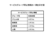
図12は、サービスグループ停止情報の一例を示す図である。図12に示すように、プリント系のグループは、暗号化通信系ログの記憶領域がログフル時にサービス停止を行い、管理系のグループは、暗号化通信系ログの記憶領域がニヤフル時にサービス停止を行う。 FIG. 12 is a diagram illustrating an example of service group stop information. As shown in FIG. 12, the print group stops service when the encrypted communication log storage area is full, and the management group stops service when the encrypted communication log storage area is full. .
図13は、変形例1における管理テーブルが保持する情報を表すクラス図である。図4との違いは、サービスグループ停止情報1301を有するところである。このサービスグループ停止情報1301は、図12に示すような情報であり、暗号化通信系ログの記憶領域がログフル又はニヤフルになったときに、停止手段303により参照される。
FIG. 13 is a class diagram showing information held in the management table in the first modification. The difference from FIG. 4 is that it has service
これより、暗号化通信系ログの記憶領域が一杯になりかけたとき(ニヤフル時)に、事前にいくつかのネットワークサービスを停止させておくことで、特定の機能を暗号化系通信系ログの記憶領域がフルになるまで使用することができる。例えば、プリンタの機能は他の機能より長く使用したい場合などに有効である。 As a result, when the storage area of the encrypted communication log is almost full (when it is nearly full), certain network functions are stopped by stopping some network services in advance. It can be used until the storage area is full. For example, the printer function is effective when it is desired to use the printer function longer than other functions.
[変形例2]
変形例2に係る画像形成装置について説明する。変形例2では、管理テーブル208のサービス停止情報を、過去のネットワークサービス利用の統計情報を基に自動で設定する。図14は、変形例2に係る画像形成装置の主要機能構成を示すブロック図である。図2との違いは、ネットワークモジュール207にサービス停止情報設定部1401が含まれることである。図14の構成において、図2と同様の構成には同じ符号を付し、その説明を省略する。
[Modification 2]
An image forming apparatus according to
サービス停止情報設定部1401は、過去のネットワークサービス利用の統計情報を基にサービス停止情報を自動で設定する。具体的には、所定時間における各ネットワークプロトコルの使用頻度を調べ、よく使用されるネットワークプロトコルの上位いくつかをログフルに設定し、残りをニヤフルに設定するようにする。また、各ネットワークプロトコルにおけるパケットの受信量などを用いても同様にサービス停止情報を設定することができる。
The service stop
これより、過去のネットワークサービス利用の統計情報を基に、サービス停止情報を自動で設定することにより、ユーザーによるサービス停止情報の設定処理を省くことができる。 Accordingly, the service stop information setting process by the user can be omitted by automatically setting the service stop information based on the past network service usage statistical information.
また、変形例2では、よく使用されるネットワークサービスをログフル時にサービス停止するようにしたが、ニヤフル時にサービス停止するようにしてもよい。ログ記憶領域に多く記憶されるサービスを停止すればその他の機能がより長く使用できるからである。つまり、よく使用されるネットワークサービスをログフル時にサービス停止するか、ニヤフル時にサービス停止するかは、各ユーザーによって決めることができる。 In the second modification, the frequently used network service is stopped when the log is full. However, the service may be stopped when the log is full. This is because the other functions can be used for a longer time if the services stored in the log storage area are stopped. In other words, each user can decide whether to stop a frequently used network service when the log is full or whether the service is stopped when the log is full.
以上、本発明の実施例について詳述したが、本発明は係る特定の実施例に限定されるものではなく、特許請求の範囲に記載された本発明の要旨の範囲内において、前述した変形例以外にも種々の変形・変更が可能である。 The embodiments of the present invention have been described in detail above. However, the present invention is not limited to the specific embodiments, and the modifications described above are within the scope of the present invention described in the claims. In addition to the above, various modifications and changes are possible.
なお、実施例1や変形例において説明した処理内容をプログラムとして記載し、このプログラムをコンピュータに実行させて前述した処理を画像形成装置に実行させることも可能である。また、このプログラムを記録媒体に記録し、このプログラムが記録された記録媒体をコンピュータに読み取らせて、前述した処理を画像形成装置に実行させることも可能である。 It is also possible to describe the processing contents described in the first embodiment and the modified example as a program and cause the image forming apparatus to execute the above-described processing by causing the computer to execute the program. It is also possible to record the program on a recording medium, cause the computer to read the recording medium on which the program is recorded, and cause the image forming apparatus to execute the processing described above.
また、実施例1に変形1又は/及び変形例2を組み合わせて画像形成装置を構成することも可能である。このとき、変形例1を組み合わせる場合には、1つのネットワークサービスには複数のサービス停止条件があることになるが、最初にサービス停止が指示されたときに、停止処理を行うようにすればよい。 In addition, the image forming apparatus can be configured by combining the first embodiment with the first modification and / or the second modification. At this time, when the first modification is combined, one network service has a plurality of service stop conditions. However, when the service stop is instructed for the first time, the stop process may be performed. .
100 画像形成装置
101 制御部
102 主記憶部
103 補助記憶部
104 印字部
105 通信制御部
106 操作部
107 ネットワークI/F
201 UI部
202 アプリケーション部
203 プリンタ
204 FAX
205 コピー
206 ミドルウェア部
207 ネットワークモジュール
208 管理テーブル
209 ログモジュール
210 ログ記録部
211 OS部
301 記録手段
302 管理手段
303 停止手段
501 待機手段
502 ネットワーク手段
503 無効化手段
1401 サービス停止情報設定部
DESCRIPTION OF
201
205
Claims (11)
前記ネットワークサービスに対応する機能毎にログをグループ化して管理する管理手段と、
前記ネットワークサービスのログを、前記ネットワークサービスに対応する機能毎に前記記憶領域に記録する記録手段と、
前記機能毎における前記記憶領域の空き状況に関する記憶状態情報に基づいて、前記管理手段に管理されるグループ毎に前記ネットワークサービスを停止する停止手段と
を備える画像形成装置。 An image forming apparatus including a storage area that executes each function and stores a log of a network service that executes the function,
Management means for grouping and managing logs for each function corresponding to the network service;
Recording means for recording the network service log in the storage area for each function corresponding to the network service;
An image forming apparatus comprising: a stopping unit that stops the network service for each group managed by the management unit based on storage state information relating to a free space state of the storage area for each function.
前記ネットワークサービス毎に設定されるサービス停止情報と前記記憶状態情報とに基づいて、前記ネットワークサービス毎に該ネットワークサービスを停止する請求項1記載の画像形成装置。 The stopping means further includes
The image forming apparatus according to claim 1, wherein the network service is stopped for each network service based on the service stop information set for each network service and the storage state information.
前記ネットワークサービスを停止する場合、前記ネットワークサービスを待機させるために前記ネットワークサービスに関する依頼情報を記録することを可能とする請求項2記載の画像形成装置。 The stopping means is
3. The image forming apparatus according to claim 2, wherein when the network service is stopped, request information related to the network service can be recorded in order to make the network service wait.
を備える請求項3記載の画像形成装置。 The image forming apparatus according to claim 3, further comprising: a network continuation unit that continues the connection with the network when the network unit is made to wait by the stop unit.
を備える請求項2乃至5いずれか一項に記載の画像形成装置。 6. The image forming apparatus according to claim 2, further comprising: a setting unit configured to set the service stop information based on statistical information of usage related to the network service.
前記ネットワークサービスに対応する機能毎にグループ化してログを管理する管理手段と、
前記ネットワークサービスのログを、前記ネットワークサービスに対応する機能毎に前記記憶領域に記録する記録手段と、
前記所定機能における前記記憶領域の空き状況に関する記憶状態情報に基づいて、前記管理手段に管理されるグループ毎に前記ネットワークサービスを停止する停止手段と
を備える画像形成装置。 An image forming apparatus that includes a storage area that executes a function including a predetermined function to be executed together with other functions and stores a log of a network service that executes the function,
Management means for managing logs by grouping for each function corresponding to the network service;
Recording means for recording the network service log in the storage area for each function corresponding to the network service;
An image forming apparatus comprising: a stopping unit that stops the network service for each group managed by the management unit based on storage state information relating to a free space state of the storage area in the predetermined function.
前記ネットワークサービスのログを、前記ネットワークサービスに対応する機能毎に前記記憶領域に記録する記録ステップと、
前記機能毎における前記記憶領域の空き状況に関する記憶状態情報に基づいて、前記管理手段に管理されるグループ毎に前記ネットワークサービスを停止する停止ステップと
を有するログ制御方法。 A log control method in an image forming apparatus, comprising: a storage area that executes each function, stores a log of a network service that executes the function; and a management unit that groups and manages logs for each function corresponding to the network service Because
A recording step of recording the network service log in the storage area for each function corresponding to the network service;
A log control method comprising: a stop step of stopping the network service for each group managed by the management unit based on storage state information relating to a free space state of the storage area for each function.
前記ネットワークサービス毎に設定されるサービス停止情報と前記記憶状態情報とに基づいて、前記ネットワークサービス毎に該ネットワークサービスを停止させる請求項8記載のログ制御方法。 The stopping step further includes:
9. The log control method according to claim 8, wherein the network service is stopped for each network service based on service stop information and the storage state information set for each network service.
前記ネットワークサービスを停止させる場合、前記ネットワークサービスを待機させるために前記ネットワークサービスに関する依頼情報を記録することを可能とする請求項9記載のログ制御方法。 The stopping step includes
The log control method according to claim 9, wherein when the network service is stopped, request information related to the network service can be recorded in order to make the network service wait.
Priority Applications (2)
| Application Number | Priority Date | Filing Date | Title |
|---|---|---|---|
| JP2008160670A JP5065173B2 (en) | 2008-06-19 | 2008-06-19 | Image forming apparatus, log control method, and program |
| US12/486,108 US8305625B2 (en) | 2008-06-19 | 2009-06-17 | Image forming apparatus, log control method, and program product |
Applications Claiming Priority (1)
| Application Number | Priority Date | Filing Date | Title |
|---|---|---|---|
| JP2008160670A JP5065173B2 (en) | 2008-06-19 | 2008-06-19 | Image forming apparatus, log control method, and program |
Publications (2)
| Publication Number | Publication Date |
|---|---|
| JP2010004267A true JP2010004267A (en) | 2010-01-07 |
| JP5065173B2 JP5065173B2 (en) | 2012-10-31 |
Family
ID=41430938
Family Applications (1)
| Application Number | Title | Priority Date | Filing Date |
|---|---|---|---|
| JP2008160670A Expired - Fee Related JP5065173B2 (en) | 2008-06-19 | 2008-06-19 | Image forming apparatus, log control method, and program |
Country Status (2)
| Country | Link |
|---|---|
| US (1) | US8305625B2 (en) |
| JP (1) | JP5065173B2 (en) |
Cited By (2)
| Publication number | Priority date | Publication date | Assignee | Title |
|---|---|---|---|---|
| JP2014235518A (en) * | 2013-05-31 | 2014-12-15 | 富士電機株式会社 | Information processing apparatus and program |
| JP2021124767A (en) * | 2020-01-31 | 2021-08-30 | キヤノン株式会社 | Image processing device, image processing method, and program |
Families Citing this family (6)
| Publication number | Priority date | Publication date | Assignee | Title |
|---|---|---|---|---|
| US9298722B2 (en) * | 2009-07-16 | 2016-03-29 | Novell, Inc. | Optimal sequential (de)compression of digital data |
| US8832103B2 (en) | 2010-04-13 | 2014-09-09 | Novell, Inc. | Relevancy filter for new data based on underlying files |
| JP2013097734A (en) | 2011-11-04 | 2013-05-20 | Ricoh Co Ltd | Controller and communication control method |
| JP6020353B2 (en) * | 2013-05-29 | 2016-11-02 | コニカミノルタ株式会社 | Information processing apparatus, image forming apparatus, remote operation method, remote control method, remote operation program, and remote control program |
| US9311311B2 (en) | 2013-09-27 | 2016-04-12 | International Business Machines Corporation | Archival management of database logs |
| JP6976748B2 (en) * | 2017-06-30 | 2021-12-08 | キヤノン株式会社 | Image forming device, server device, information processing system, image forming device control method, and program |
Citations (1)
| Publication number | Priority date | Publication date | Assignee | Title |
|---|---|---|---|---|
| JP2008065426A (en) * | 2006-09-05 | 2008-03-21 | Ricoh Co Ltd | Image forming method, device, and image forming system |
Family Cites Families (5)
| Publication number | Priority date | Publication date | Assignee | Title |
|---|---|---|---|---|
| JP2001273098A (en) | 2000-03-23 | 2001-10-05 | Canon Inc | The image forming device, its control method and storage medium |
| JP4531966B2 (en) * | 2000-12-06 | 2010-08-25 | 東芝テック株式会社 | Image forming apparatus |
| JP2006041764A (en) | 2004-07-23 | 2006-02-09 | Ricoh Co Ltd | Log recording apparatus, log recording program, and recording medium |
| JP2006236269A (en) * | 2005-02-28 | 2006-09-07 | Oki Data Corp | Image forming device and upper level terminal device |
| US20080112009A1 (en) * | 2006-11-15 | 2008-05-15 | Yoshiharu Tojo | Image processing apparatus, log recording method, and storage medium |
-
2008
- 2008-06-19 JP JP2008160670A patent/JP5065173B2/en not_active Expired - Fee Related
-
2009
- 2009-06-17 US US12/486,108 patent/US8305625B2/en active Active
Patent Citations (1)
| Publication number | Priority date | Publication date | Assignee | Title |
|---|---|---|---|---|
| JP2008065426A (en) * | 2006-09-05 | 2008-03-21 | Ricoh Co Ltd | Image forming method, device, and image forming system |
Cited By (3)
| Publication number | Priority date | Publication date | Assignee | Title |
|---|---|---|---|---|
| JP2014235518A (en) * | 2013-05-31 | 2014-12-15 | 富士電機株式会社 | Information processing apparatus and program |
| JP2021124767A (en) * | 2020-01-31 | 2021-08-30 | キヤノン株式会社 | Image processing device, image processing method, and program |
| JP7431596B2 (en) | 2020-01-31 | 2024-02-15 | キヤノン株式会社 | Image processing device, image processing method and program |
Also Published As
| Publication number | Publication date |
|---|---|
| US8305625B2 (en) | 2012-11-06 |
| JP5065173B2 (en) | 2012-10-31 |
| US20090316200A1 (en) | 2009-12-24 |
Similar Documents
| Publication | Publication Date | Title |
|---|---|---|
| JP5065173B2 (en) | Image forming apparatus, log control method, and program | |
| JP4440107B2 (en) | Methods and configurations for using shared resources in a network | |
| JP2008071085A (en) | Image processor and log transfer method | |
| JP2004171324A (en) | Job management device | |
| JP2013080387A (en) | Information processing apparatus, information processing method, and program | |
| JP2010152838A (en) | Image forming device, control method and program | |
| US20180173473A1 (en) | Method for operating a print server for digital high-capacity printing systems | |
| US9116649B2 (en) | Image forming apparatus with unit determining whether operation information is transmitted to log storage server | |
| JP3492249B2 (en) | PRINTING APPARATUS, PRINTING SYSTEM, AND CONTROL METHOD THEREOF | |
| JP5491972B2 (en) | Duplex server system, file operation method, and file operation program | |
| US20200068088A1 (en) | Processing system, control system, relay apparatus, and communication method | |
| US10303404B2 (en) | Method for operating a print server for digital high-capacity printing systems | |
| JP2008171323A (en) | Job management device, job management method, job management program and storage medium | |
| JP4529788B2 (en) | Distribution apparatus and distribution control method | |
| JP2012063908A (en) | Job management device, image processor, printing system, and job management program | |
| JP4671438B2 (en) | Server apparatus and control method thereof | |
| JP2011191942A (en) | Processing method and apparatus | |
| JP2008129828A (en) | Dynamic allocation method of blade server | |
| CN110866743A (en) | Providing apparatus, processing system, and communication method | |
| US20230342235A1 (en) | Computer-readable recording medium storing information processing program, information processing method, and system | |
| JP2006268193A (en) | Management system, management center, and management method | |
| JP4967473B2 (en) | Audit log generation device, audit event recording program, and image processing device | |
| JP2000003259A (en) | Lan system and digital copying machine management server | |
| JP2023026094A (en) | Information processing device, information processing method, and program | |
| JP2023136875A (en) | Communication control device, communication control method, and program |
Legal Events
| Date | Code | Title | Description |
|---|---|---|---|
| A621 | Written request for application examination |
Free format text: JAPANESE INTERMEDIATE CODE: A621 Effective date: 20110113 |
|
| A977 | Report on retrieval |
Free format text: JAPANESE INTERMEDIATE CODE: A971007 Effective date: 20120518 |
|
| A131 | Notification of reasons for refusal |
Free format text: JAPANESE INTERMEDIATE CODE: A131 Effective date: 20120529 |
|
| A521 | Request for written amendment filed |
Free format text: JAPANESE INTERMEDIATE CODE: A523 Effective date: 20120628 |
|
| TRDD | Decision of grant or rejection written | ||
| A01 | Written decision to grant a patent or to grant a registration (utility model) |
Free format text: JAPANESE INTERMEDIATE CODE: A01 Effective date: 20120717 |
|
| A01 | Written decision to grant a patent or to grant a registration (utility model) |
Free format text: JAPANESE INTERMEDIATE CODE: A01 |
|
| A61 | First payment of annual fees (during grant procedure) |
Free format text: JAPANESE INTERMEDIATE CODE: A61 Effective date: 20120809 |
|
| R150 | Certificate of patent or registration of utility model |
Ref document number: 5065173 Country of ref document: JP Free format text: JAPANESE INTERMEDIATE CODE: R150 Free format text: JAPANESE INTERMEDIATE CODE: R150 |
|
| FPAY | Renewal fee payment (event date is renewal date of database) |
Free format text: PAYMENT UNTIL: 20150817 Year of fee payment: 3 |
|
| LAPS | Cancellation because of no payment of annual fees |