JP2010004089A - Communication system, communication device, and communication method used for them - Google Patents
Communication system, communication device, and communication method used for them Download PDFInfo
- Publication number
- JP2010004089A JP2010004089A JP2008158587A JP2008158587A JP2010004089A JP 2010004089 A JP2010004089 A JP 2010004089A JP 2008158587 A JP2008158587 A JP 2008158587A JP 2008158587 A JP2008158587 A JP 2008158587A JP 2010004089 A JP2010004089 A JP 2010004089A
- Authority
- JP
- Japan
- Prior art keywords
- communication
- band
- transmission path
- blocking
- received
- Prior art date
- Legal status (The legal status is an assumption and is not a legal conclusion. Google has not performed a legal analysis and makes no representation as to the accuracy of the status listed.)
- Granted
Links
Images


Classifications
-
- H—ELECTRICITY
- H04—ELECTRIC COMMUNICATION TECHNIQUE
- H04J—MULTIPLEX COMMUNICATION
- H04J3/00—Time-division multiplex systems
- H04J3/16—Time-division multiplex systems in which the time allocation to individual channels within a transmission cycle is variable, e.g. to accommodate varying complexity of signals, to vary number of channels transmitted
- H04J3/1682—Allocation of channels according to the instantaneous demands of the users, e.g. concentrated multiplexers, statistical multiplexers
-
- H—ELECTRICITY
- H04—ELECTRIC COMMUNICATION TECHNIQUE
- H04L—TRANSMISSION OF DIGITAL INFORMATION, e.g. TELEGRAPHIC COMMUNICATION
- H04L47/00—Traffic control in data switching networks
- H04L47/10—Flow control; Congestion control
-
- H—ELECTRICITY
- H04—ELECTRIC COMMUNICATION TECHNIQUE
- H04L—TRANSMISSION OF DIGITAL INFORMATION, e.g. TELEGRAPHIC COMMUNICATION
- H04L47/00—Traffic control in data switching networks
- H04L47/10—Flow control; Congestion control
- H04L47/25—Flow control; Congestion control with rate being modified by the source upon detecting a change of network conditions
Abstract
Description
本発明は通信システム、通信装置及びそれらに用いる通信方法に関し、特に通信帯域が変化する伝送路における通信方法に関する。 The present invention relates to a communication system, a communication apparatus, and a communication method used therefor, and more particularly to a communication method in a transmission path in which a communication band changes.
大容量のデータを送受信する際には、大容量の伝送路を施設し、借用した場合、多大な費用がかかるため、低容量の回線を複数束ねて大容量伝送路として利用する方法がある。このように、大容量回線を複数の低容量回線に分割する逆多重化技術が公開されている(例えば、特許文献1参照)。 When transmitting and receiving large-capacity data, if a large-capacity transmission line is installed and borrowed, it is very expensive. Therefore, there is a method in which a plurality of low-capacity lines are bundled and used as a large-capacity transmission path. In this way, a demultiplexing technique for dividing a large capacity line into a plurality of low capacity lines has been disclosed (see, for example, Patent Document 1).
この逆多重化技術を使って送受信を行う場合には、逆多重化されている一部の回線が切断されると、他の回線が送受信可能にもかかわらず、一切の通信が不可能となることがある。 When transmission / reception is performed using this demultiplexing technology, if some of the demultiplexed lines are disconnected, no communication is possible even though other lines can be transmitted / received. Sometimes.
この送受信が不可能になる場合について図4を参照して説明する。図4においては、電話機(#3)5−1から電話機(4)5−2、FTP(File Transfer Protocol)通信機(#3)6−1からFTP通信機(#4)6−2、HTTP(Hyper Text Transfer Protocol)通信機(#3)7−1からHTTP通信機(#4)7−2へデータを送信するモデルを示している。また、これらの通信は、多重化グループ700によって多重化されている。
The case where this transmission / reception becomes impossible will be described with reference to FIG. In FIG. 4, the telephone (# 3) 5-1 to the telephone (4) 5-2, the FTP (File Transfer Protocol) communication device (# 3) 6-1 to the FTP communication device (# 4) 6-2, HTTP (Hyper Text Transfer Protocol) This shows a model for transmitting data from the communication device (# 3) 7-1 to the HTTP communication device (# 4) 7-2. These communications are multiplexed by a
上記の構成においては、伝送路600を送受信可能な帯域が減少し、FTP通信を行う回線とHTTP通信を行う回線とが切断された場合、電話の回線のみ通信ができる状態となる。しかしながら、受信側の多重化グループ800では、複数の回線が切断されて必要な情報がないため、電話機(#4)6−2を含め多重化グループ800のすべての通信が不可能となる。
In the above configuration, when the bandwidth that can be transmitted and received through the
本発明に関連する通信システムの課題について、図5を参照して説明する。図5においては、通信装置8−1と通信装置8−2とが通信を行っている。通信装置8−1は、通信装置8−2との間に逆多重化グループ900を作成し、通信を行っている。
The problem of the communication system related to the present invention will be described with reference to FIG. In FIG. 5, the communication device 8-1 and the communication device 8-2 communicate with each other. The communication device 8-1 creates a
MUX(Multiplexing)装置9−1は、入力された複数の回線901−1〜901−jを一つに束ね、AMR(Adaptive Multi Rate)を用いた無線等の帯域が変動する伝送路902を利用して対向先のMUX装置9−2にデータを送信する。MUX装置9−2では、一つに束ねられた回線902を複数の回線903−1〜903−kに復元し、それらの複数の回線903−1〜903−kを多重化グループ900として通信装置8−2に送信する。
The MUX (Multiplexing) device 9-1 bundles a plurality of input lines 901-1 to 901-j and uses a
MUX装置9−1とMUX装置9−2との間の伝送路902の帯域が減少した場合には、MUX装置9−1,9−2によって無作為にデータが廃棄される。本発明に関連する通信システムでは、この無作為の廃棄によって、優先度の高いデータが廃棄されてしまうという問題がある。
When the bandwidth of the
そこで、本発明の目的は上記の問題点を解消し、伝送路の帯域が減少した場合でも無作為にデータが廃棄されるのを防ぐことができ、帯域の変化に対応することができる通信システム、通信装置及びそれらに用いる通信方法を提供することにある。 SUMMARY OF THE INVENTION Accordingly, an object of the present invention is to solve the above-mentioned problems, prevent a data from being discarded at random even when the bandwidth of the transmission path is reduced, and cope with a change in the bandwidth. It is to provide a communication apparatus and a communication method used for them.
本発明による通信システムは、通信帯域が変化する伝送路を用いて通信装置間の通信を行う通信システムであって、
複数の回線をデータの優先度に応じて複数の多重化グループに分割し、
前記通信装置は、前記伝送路の通信帯域の増減を検出する検出手段と、前記検出手段の検出結果に応じて前記複数の多重化グループ各々に属する回線の閉塞または解放を行う閉塞手段とを備えている。
A communication system according to the present invention is a communication system that performs communication between communication devices using a transmission path whose communication band changes.
Divide multiple lines into multiple multiplexing groups according to data priority,
The communication apparatus includes detection means for detecting an increase / decrease in a communication band of the transmission path, and blocking means for blocking or releasing a line belonging to each of the plurality of multiplexing groups according to a detection result of the detection means. ing.
本発明による通信装置は、通信帯域が変化する伝送路を用いて通信を行う通信装置であって、
複数の回線をデータの優先度に応じて複数の多重化グループに分割し、
前記伝送路の通信帯域の増減を検出する検出手段と、前記検出手段の検出結果に応じて前記複数の多重化グループ各々に属する回線の閉塞または解放を行う閉塞手段とを備えている。
A communication apparatus according to the present invention is a communication apparatus that performs communication using a transmission path whose communication band changes,
Divide multiple lines into multiple multiplexing groups according to data priority,
Detection means for detecting an increase or decrease in the communication band of the transmission path, and blocking means for blocking or releasing lines belonging to each of the plurality of multiplexed groups according to the detection result of the detection means.
本発明による通信方法は、通信帯域が変化する伝送路を用いて通信装置間の通信を行う通信システムに用いる通信方法であって、
複数の回線をデータの優先度に応じて複数の多重化グループに分割し、
前記伝送路の通信帯域の増減を検出する検出ステップと、前記検出ステップの検出結果に応じて前記複数の多重化グループ各々に属する回線の閉塞または解放を行う閉塞ステップとを備えている。
A communication method according to the present invention is a communication method used in a communication system that performs communication between communication devices using a transmission path whose communication band changes.
Divide multiple lines into multiple multiplexing groups according to data priority,
A detection step for detecting an increase or decrease in the communication band of the transmission path; and a blocking step for blocking or releasing a line belonging to each of the plurality of multiplexed groups according to a detection result of the detection step.
本発明は、上記のような構成及び動作とすることで、伝送路の帯域が減少した場合でも無作為にデータが廃棄されるのを防ぐことができ、帯域の変化に対応することができるという効果が得られる。 By adopting the above-described configuration and operation, the present invention can prevent random discarding of data even when the bandwidth of the transmission path is reduced, and can cope with a change in bandwidth. An effect is obtained.
次に、本発明の実施の形態について図面を参照して説明する。まず、本発明による通信システムの概要について説明する。本発明による通信システムは、IMA[Inverse Multiplexing on ATM(Asynchronous Transfer Mode)]とAMR(Adaptive Multi Rate)とを適用した無線通信等の通信帯域が変化する伝送路を用いた通信において、データの優先度に応じて多重化グループを分割し、通信帯域が減少した際に、優先度の低いグループの回線から閉塞していくことにより、通信帯域の減少に対応し、優先度の高いデータを廃棄することなく送信を可能にしたことを特徴としている。 Next, embodiments of the present invention will be described with reference to the drawings. First, an outline of a communication system according to the present invention will be described. The communication system according to the present invention provides priority to data in communication using a transmission path in which a communication band changes, such as wireless communication using IMA [Inverse Multiplexing on ATM (Asynchronous Transfer Mode)] and AMR (Adaptive Multi Rate). Multiplexed groups are divided according to the degree, and when the communication band decreases, the line of the group with lower priority is blocked to deal with the decrease in communication band and discard high-priority data. It is characterized by enabling transmission without any problems.
本発明による通信システムでは、逆多重化再構成回路において、予め決められた多重化グループ毎に束ねて帯域変動検出回路に送信する。帯域変動検出回路では、逆多重化再構成回路から受信するデータ量(送受信する帯域)と、出力する伝送路の帯域(送受信可能帯域)とを比較して帯域制御を行う。 In the communication system according to the present invention, the demultiplexing reconfiguration circuit bundles and transmits to the band fluctuation detection circuit for each predetermined multiplexing group. In the band fluctuation detection circuit, band control is performed by comparing the amount of data received from the demultiplexing reconfiguration circuit (band to be transmitted / received) and the band of the output transmission path (band that can be transmitted / received).
本発明による通信システムでは、伝送路にて送受信可能な帯域(伝送路帯域に相当)が送受信する帯域(送受信データ量に相当)より減少または増加した場合、回線を閉塞・解放することによって、帯域の変化に対応することが可能となる。また、本発明による通信システムでは、回線を閉塞・解放する閉塞回路に対して予め優先順位が決められており、その順位に従って閉塞回路を選択している。 In the communication system according to the present invention, when the band that can be transmitted / received on the transmission line (corresponding to the transmission line band) is decreased or increased from the transmission / reception band (corresponding to the transmission / reception data amount), the line is blocked and released. It becomes possible to cope with the change of. Further, in the communication system according to the present invention, the priority order is determined in advance for the block circuit that blocks and releases the line, and the block circuit is selected according to the rank.
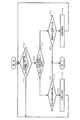
図1は本発明の第1の実施の形態による通信システムの構成例を示すブロック図である。図1において、本発明の第1の実施の形態による通信システムは、通信装置1と、伝送路100とを含んで構成されている。通信装置1は、帯域変動検出回路11と、閉塞回路(#1)12−1,・・・,(#2)12−m,(#3)13−1,・・・,(#4)13−nと、逆多重化再構成回路14と、通信機器15とを含んで構成されている。
FIG. 1 is a block diagram showing a configuration example of a communication system according to the first exemplary embodiment of the present invention. In FIG. 1, the communication system according to the first exemplary embodiment of the present invention includes a
通信装置1内においては、多重化グループ(#1000)300及び多重化グループ(#10,#11)201,202が形成されている。多重化グループ(#1000)300は、逆多重化再構成回路14にて通信機器14から送受信する回線のグループである。また、多重化グループ(#10,#11)201,202は、逆多重化再構成が行われたグループである。
In the
伝送路100においては、多重化グループ(#1)101と多重化グループ(#2)102とが形成されている。多重化グループ(#1)101は、多重化グループ(#10)201が帯域変動検出回路11を通過した後のグループであり、多重化グループ(#2)102は、多重化グループ(#11)202が帯域変動検出回路11を通過した後のグループである。
In the
この場合、多重化グループ(#1000)300及び多重化グループ(#10,#11)201,202と、多重化グループ(#1)101及び多重化グループ(#2)102とは、低容量の回線を複数束ねて大容量伝送路として利用するものである。 In this case, the multiplexing group (# 1000) 300 and the multiplexing groups (# 10, # 11) 201 and 202 and the multiplexing group (# 1) 101 and the multiplexing group (# 2) 102 are low capacity. A plurality of lines are bundled and used as a large capacity transmission line.
逆多重化再構成回路14は、多重化グループ(#1000)300を流れるデータの優先度によって再グループ化を行う。閉塞回路(#1)12−1,・・・,(#2)12−m,(#3)13−1,・・・,(#4)13−nは、回線を閉塞または解放する。帯域変動検出回路11は、伝送路100での通信帯域の変化を監視検出する。
The demultiplexing reconfiguration circuit 14 performs regrouping according to the priority of data flowing through the multiplexing group (# 1000) 300. Blocking circuits (# 1) 12-1, ..., (# 2) 12-m, (# 3) 13-1, ..., (# 4) 13-n block or release the line. The band
本実施の形態では、事前準備として、多重化グループ(#1000)300を優先順位によって多重化グループ(#10)201及び多重化グループ(#11)202に分割する。この分割数は任意である。 In this embodiment, as a preliminary preparation, the multiplexed group (# 1000) 300 is divided into a multiplexed group (# 10) 201 and a multiplexed group (# 11) 202 according to priority. This division number is arbitrary.
また、本実施の形態は、双方向通信に適用可能である。閉塞回路(#1)12−1,・・・,(#2)12−m,(#3)13−1,・・・,(#4)13−nは、図1において、帯域変動検出回路11の出力側にのみ表記しているが、双方向として伝送路側にも配設可能である。
Further, this embodiment is applicable to bidirectional communication. Blocking circuits (# 1) 12-1, ..., (# 2) 12-m, (# 3) 13-1, ..., (# 4) 13-n are shown in FIG. Although shown only on the output side of the
さらに、本実施の形態において、送受信可能な帯域(伝送路帯域に相当)は、既存の技術によって計測可能であり、随時、そのデータを取得することができる。送受信する帯域(送受信データ量に相当)は、各データの受信ポートが決められており、その通信量から計測することができる。尚、これらの帯域を計測する技術についての説明は省略する。 Furthermore, in the present embodiment, a band that can be transmitted and received (corresponding to a transmission line band) can be measured by an existing technique, and the data can be acquired as needed. The transmission / reception bandwidth (corresponding to the amount of transmitted / received data) is determined by the reception port of each data, and can be measured from the communication amount. A description of the technique for measuring these bands will be omitted.
閉塞回路(#1)12−1,・・・,(#2)12−m,(#3)13−1,・・・,(#4)13−nの優先順位は、帯域変動検出回路11のデータ出力ポートによって決められ、優先順位テーブル(図示せず)に予め優先順位を設定しておく。本実施の形態における多重化グループは、2つのグループについて記載しているが、これらのグループは、3以上の複数個設定することが可能である。 .., (# 2) 12-m, (# 3) 13-1,..., (# 4) 13-n have priority given to the band fluctuation detection circuit. 11 data output ports, and priorities are set in advance in a priority table (not shown). Although the multiplexing group in the present embodiment describes two groups, it is possible to set a plurality of groups of three or more.
本実施の形態では、事前準備が完了した状態で、伝送路100に対して送信可能な帯域が減少したことを帯域変動検出回路11が検出した場合、分割した多重化グループ(#10)201及び多重化グループ(#11)202のうち優先度が低い多重化グループ(#11)202の回線を閉塞回路(#4)13−nによって閉塞する。この閉塞動作は、帯域減少分だけ繰り返し行い、送信帯域を減少させる。
In the present embodiment, when the band
また、本実施の形態では、帯域変動検出回路11が送信可能な帯域の増加を検知し、現在閉塞状態にある回線が存在する場合、帯域増加分だけ閉塞回路(#1)12−1,・・・,(#2)12−m,(#3)13−1,・・・,(#4)13−nによって回線を解放し、送信帯域を増加させる。
Also, in this embodiment, when the bandwidth
以下、上述した本発明の第1の実施の形態による通信システムの各ブロックについて詳細に説明する。 Hereinafter, each block of the communication system according to the first embodiment of the present invention described above will be described in detail.
伝送路100は、多重化グループ(#1)101及び多重化グループ(#2)102が送受信される伝送路であり、送受信可能な帯域が変動する可能性がある伝送路である。
The
多重化グループ(#1)101は、複数の回線からなる多重化グループ(#10)201が閉塞回路(#1)12−1,・・・,(#2)12−mと帯域変動検出回路11とを通過した後の多重化グループである。 The multiplexing group (# 1) 101 includes a multiplexing group (# 10) 201 composed of a plurality of lines, a block circuit (# 1) 12-1, ..., (# 2) 12-m, and a band fluctuation detection circuit. 11 is a multiplex group after passing through 11.
多重化グループ(#1)101は、帯域変動検出回路11が帯域の減少を検出すると、帯域減少幅に応じて回線が閉塞し、多重化グループ(#10)201に比較して、その帯域が狭くなる。また、多重化グループ(#1)101は、多重化グループ(#2)102に比べて優先順位が同じか、高いデータが送信される多重化グループである。
In the multiplexing group (# 1) 101, when the band
多重化グループ(#2)102は、複数の回線からなる多重化グループ(#11)202が閉塞回路(#3)13−1,・・・,(#4)13−nと帯域変動検出回路11とを通過した後の多重化グループである。 In the multiplexing group (# 2) 102, the multiplexing group (# 11) 202 composed of a plurality of lines is replaced by the blocking circuit (# 3) 13-1, ..., (# 4) 13-n and the band fluctuation detection circuit. 11 is a multiplex group after passing through 11.
多重化グループ(#2)102は、帯域変動検出回路11が帯域の減少を検出すると、帯域減少幅に応じて回線が閉塞し、多重化グループ(#11)202に比較して、その帯域が狭くなる。また、多重化グループ(#2)102は、多重化グループ(#1)101に比べて優先順位が同じか、低いデータが送信される多重化グループである。
In the multiplexing group (# 2) 102, when the band
帯域変動検出回路11は、逆多重化再構成回路14から多重化グループ(#10)201及び多重化グループ(#11)202を閉塞回路(#1)12−1,・・・,(#2)12−m,(#3)13−1,・・・,(#4)13−nを通して入力し、回線の閉塞・解放を行って帯域の調整をし、伝送路100に送出する。
The band
また、帯域変動検出回路11は、伝送路100から入力した多重化グループ(#1)101と多重化グループ(#2)102とを、閉塞回路(#1)12−1,・・・,(#2)12−m,(#3)13−1,・・・,(#4)13−nを通して逆多重化再構成回路14に送信する。
In addition, the band
さらに、帯域変動検出回路11は、伝送路100の送受信可能な帯域が変動した場合、その変動を検出し、閉塞回路(#1)12−1,・・・,(#2)12−m,(#3)13−1,・・・,(#4)13−nを制御して回線の閉塞・解放操作を行う。
Furthermore, when the band that can be transmitted and received in the
帯域変動検出回路11は、一定以上の帯域減少を検出し、閉塞可能な回線が存在する場合、減少幅に応じて閉塞回路(#1)12−1,・・・,(#2)12−m,(#3)13−1,・・・,(#4)13−nを閉塞させる。帯域変動検出回路11は、一定以上の帯域増加を検出し、閉塞状態である回線が存在する場合、増加幅に応じて回線を解放させる。
The band
閉塞回路(#1)12−1,・・・,(#2)12−m,(#3)13−1,・・・,(#4)13−nは、逆多重化再構成回路14と帯域変動検出回路11との間の多重化グループ(#10)201及び多重化グループ(#11)202に含まれる回線の閉塞・解放を行う回路である。
The blocking circuits (# 1) 12-1, ..., (# 2) 12-m, (# 3) 13-1, ..., (# 4) 13-n are demultiplexed reconfiguration circuit 14. And a block included in the multiplexing group (# 10) 201 and the multiplexing group (# 11) 202 between the network
閉塞回路(#1)12−1,・・・,(#2)12−m,(#3)13−1,・・・,(#4)13−nは、帯域変動検出回路11で一定以上の帯域減少を検出し、閉塞可能な回線が存在する場合、減少幅に応じて回線に閉塞する。また、閉塞回路(#1)12−1,・・・,(#2)12−m,(#3)13−1,・・・,(#4)13−nは、帯域変動検出回路11で一定以上の帯域増加を検出し、閉塞状態である回線が存在する場合、増加幅に応じて回線を解放する。
Blocking circuits (# 1) 12-1, ..., (# 2) 12-m, (# 3) 13-1, ..., (# 4) 13-n are constant in the band
多重化グループ(#10)201は、逆多重化再構成回路14と帯域変動検出回路11との間の多重化グループであり、多重化グループ(#11)202と比較して優先度が同じか、高いデータを集約して再構成した後の多重化グループである。
The multiplexing group (# 10) 201 is a multiplexing group between the demultiplexing reconfiguration circuit 14 and the band
多重化グループ(#11)202は、逆多重化再構成回路14と帯域変動検出回路11との間の多重化グループであり、多重化グループ(#10)201と比較して優先度が同じか、低いデータを集約して再構成した後の多重化グループである。
The multiplexing group (# 11) 202 is a multiplexing group between the demultiplexing reconfiguration circuit 14 and the band
逆多重化再構成回路14は、多重化グループ(#1000)300から入力されたさまざまな優先度が混在するデータを、優先度が高いデータを多重化グループ(#10)201に、優先度が低いデータを多重化グループ(#11)202にそれぞれ再構成する。 The demultiplexing / reconfiguring circuit 14 sets the data having different priorities input from the multiplexing group (# 1000) 300 to the multiplexing group (# 10) 201 with the higher priority data. The low data is reconfigured in the multiplexed group (# 11) 202, respectively.
また、逆多重化再構成回路14は、入力された多重化グループ(#10)201と多重化グループ(#11)202とを束ねて多重化グループ(#1000)300として再構成を行う。 The demultiplexing reconfiguration circuit 14 reconfigures the multiplexed group (# 1000) 300 by bundling the input multiplexed group (# 10) 201 and multiplexed group (# 11) 202 together.
多重化グループ(#1000)は、通信機器15と逆多重化再構成回路14との間の回線を束ねた多重化グループである。多重化グループ(#1000)では、さまざまな優先度のデータが同一多重化グループ内に混在している。通信機器15は、さまざまな優先度のデータが混在して送受信される通信機器である。 The multiplexing group (# 1000) is a multiplexing group in which the lines between the communication device 15 and the demultiplexing reconfiguration circuit 14 are bundled. In the multiplexing group (# 1000), data of various priorities are mixed in the same multiplexing group. The communication device 15 is a communication device that transmits and receives data with various priorities in a mixed manner.
図2は本発明の第1の実施の形態による通信装置1の動作を示すフローチャートである。図2に示す処理は、帯域変動検出回路11の処理内容に一致する。また、回線閉塞ならびに回線解放の処理については、優先順位に応じた閉塞回路(#1)12−1,・・・,(#2)12−m,(#3)13−1,・・・,(#4)13−nの選択処理も含む。
FIG. 2 is a flowchart showing the operation of the
本実施の形態では、動作を行う前提として、多重化グループ(#1000)300を、優先度によって分割する逆多重化の再構築を行う必要がある。多重化グループの再構成は、逆多重化再構成回路14によって行われる。 In the present embodiment, as a premise for performing the operation, it is necessary to reconstruct demultiplexing that divides the multiplexing group (# 1000) 300 according to priority. Multiplexing group reconstruction is performed by the demultiplexing reconstruction circuit 14.
逆多重化再構成回路14は、多重化グループ(#1000)300において送信されるさまざまな優先度のデータを、優先度が高いデータを多重化グループ(#10)201に、優先度が低いデータを多重化グループ(#11)202に多重化グループを再構成する。 The demultiplexing reconfiguration circuit 14 transmits data of various priorities transmitted in the multiplexing group (# 1000) 300, data having a high priority to the multiplexing group (# 10) 201, and data having a low priority. Is reconfigured into a multiplexed group (# 11) 202.
逆多重化再構成回路14は、この再構成済みの多重化グループ(#10)及び多重化グループ(#11)を用いて閉塞回路(#1)12−1,・・・,(#2)12−m,(#3)13−1,・・・,(#4)13−nを通した帯域変動検出回路11と送受信を行う。
The demultiplexing reconfiguration circuit 14 uses the reconfigured multiplexed group (# 10) and multiplexed group (# 11) to block the circuit (# 1) 12-1, ..., (# 2). 12-m, (# 3) 13-1,..., (# 4) 13-n performs transmission / reception with the band
帯域が変動した際の詳細な動作を、図2を参照して説明する。帯域変動検出回路11においては、帯域の変動が検出されるまで帯域の監視を継続する(図2ステップS1)。
A detailed operation when the band fluctuates will be described with reference to FIG. The band
もしも、それぞれの回線帯域以上の帯域の変動があった場合、帯域変動検出回路11は、伝送路100に送受信可能な帯域と送受信帯域とを比較する(図2ステップS2)。
If there is a fluctuation of the band over the respective line band, the band
帯域変動検出回路11は、送受信可能帯域が送受信帯域よりも低い場合、優先度の低いデータを送受信している多重化グループ(#11)202で閉塞状態の回線を閉塞可能な回線とみなし、その存在の有無を調べる(図2ステップS3)。
When the transmittable / receiveable band is lower than the transmit / receive band, the band
この場合、帯域変動検出回路11は、閉塞可能な回線が存在しなければ、処理を終了する。もしも、閉塞可能な回線が存在する場合、帯域変動検出回路11は、回線を一つ閉塞し(図2ステップS4)、ステップS1の処理に戻る。
In this case, the band
一方、帯域変動検出回路11は、送受信可能帯域が送受信帯域よりも高い場合、閉塞状態の回線の有無を調べる(図2ステップS5)。もしも、閉塞状態の回線が存在しなければ、帯域変動検出回路11は、処理を終了する。これに対し、閉塞状態の回線が存在する場合、帯域変動検出回路11は、回線を一つ解放し(図2ステップS6)、ステップS1の処理に戻る。
On the other hand, when the transmittable / receiveable band is higher than the transmit / receive band, the band
このように、本実施の形態では、優先度の高いデータを送受信する多重化グループ(#10)201と優先度が低い多重化グループ(#11)202とに分割しているため、伝送路100の送受信可能な帯域が送受信する帯域より減少した場合、優先度の低い多重化グループ(#11)202の回線を閉塞することによって、優先度の高い多重化グループ(#10)201のデータ送受信に影響を与えない。
As described above, in this embodiment, the
また、本実施の形態では、伝送路100にて送受信可能な帯域(伝送路帯域に相当)が送受信する帯域(送受信データ量に相当)より減少・増加した場合、回線を閉塞・解放することによって、帯域の変化に対応可能である。 Also, in this embodiment, when the band that can be transmitted / received on the transmission line 100 (corresponding to the transmission line band) decreases or increases from the transmission / reception band (corresponding to the transmission / reception data amount), the line is blocked / released. It is possible to cope with the change of the band.
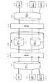
図3は本発明の第1の実施の形態による通信システムの効果を説明するための図である。この図3を参照して、本実施の形態において、伝送路100の通信帯域が減少した場合でも、優先度の高いデータに影響が及ばない例について説明する。
FIG. 3 is a diagram for explaining the effect of the communication system according to the first embodiment of the present invention. With reference to FIG. 3, an example will be described in the present embodiment in which even if the communication band of the
図3に示す例では、電話機(#1)2−1が電話機(#2)2−2と、FTP(File Transfer Protocol)通信機(#1)3−1がFTP通信機(#2)3−2と、HTTP(Hyper Text Transfer Protocol)通信機(#1)4−1がHTTP通信機(#2)4−2と通信し、それらのデータが一つの多重化グループ400に集約されている。
In the example shown in FIG. 3, the telephone (# 1) 2-1 is the telephone (# 2) 2-2, and the FTP (File Transfer Protocol) communication device (# 1) 3-1 is the FTP communication device (# 2) 3. -2 and an HTTP (Hyper Text Transfer Protocol) communication device (# 1) 4-1 communicate with the HTTP communication device (# 2) 4-2, and their data are collected in one
また、図3に示す例では、この多重化グループ400を通信装置1−1によって、優先度の高い電話通信を多重化グループ101に、優先度の低いFTP通信とHTTP通信とを多重化グループ102にそれぞれ分割している。
In the example shown in FIG. 3, the
この再構成された2つの多重化グループ101,102が伝送路100を通って通信装置1−2へ送信される。通信装置1−2では、分割された2つの多重化グループ101,102を結合し、多重化グループ500に復元する。尚、通信装置1−1,1−2は、上記の図1に示す通信装置1と同様の構成となっている。
The reconfigured two multiplexed
伝送路100の帯域が減少すると、通信装置1−1はこれを検知し、優先度の低いFTP通信とHTTP通信とを送受信する多重化グループ102の回線を閉塞する。これによって、FTP通信とHTTP通信とは、送受信が不可能となる。しかしながら、電話通信は、別の多重化グループ101としているため、帯域変動の影響を受けず、その通信が可能となる。
When the bandwidth of the
1,1−1,1−2 通信装置
2−1 電話機(#1)
2−2 電話機(#2)
3−1 FTP通信機(#1)
3−2 FTP通信機(#2)
4−1 HTTP通信機(#1)
4−2 HTTP通信機(#2)
11 帯域変動検出回路
12−1 閉塞回路(#1)
12−m 閉塞回路(#2)
13−1 閉塞回路(#3)
13−n 閉塞回路(#4)
14 逆多重化再構成回路
15 通信機器15
100 伝送路
101 多重化グループ(#1)
102 多重化グループ(#2)
201 多重化グループ(#10)
202 多重化グループ(#11)
300 多重化グループ(#1000)
400,500 多重化グループ
1,1-1,1-2 communication device
2-1 Telephone (# 1)
2-2 Telephone (# 2)
3-1 FTP communication machine (# 1)
3-2 FTP communication machine (# 2)
4-1 HTTP communication device (# 1)
4-2 HTTP communication device (# 2)
11 Band fluctuation detection circuit
12-1 Blocking circuit (# 1)
12-m Blocking circuit (# 2)
13-1 Blocking circuit (# 3)
13-n Blocking circuit (# 4)
14 Demultiplexing reconstruction circuit
15 Communication equipment 15
100 transmission line
101 Multiplexing group (# 1)
102 Multiplexing group (# 2)
201 Multiplexing group (# 10)
202 Multiplexing group (# 11)
300 Multiplexing group (# 1000)
400,500 Multiplexing group
Claims (18)
複数の回線をデータの優先度に応じて複数の多重化グループに分割し、
前記通信装置は、前記伝送路の通信帯域の増減を検出する検出手段と、前記検出手段の検出結果に応じて前記複数の多重化グループ各々に属する回線の閉塞または解放を行う閉塞手段とを有することを特徴とする通信システム。 A communication system that performs communication between communication devices using a transmission line whose communication band changes,
Divide multiple lines into multiple multiplexing groups according to data priority,
The communication apparatus includes detection means for detecting an increase / decrease in the communication band of the transmission path, and blocking means for blocking or releasing a line belonging to each of the plurality of multiplexed groups according to a detection result of the detection means. A communication system characterized by the above.
前記検出手段は、前記逆多重化再構成手段から受信するデータ量と、当該データを出力する前記伝送路の帯域とを比較して通信帯域の増減を検出することを特徴とする請求項1記載の通信システム。 The communication apparatus includes demultiplexing reconfiguration means for bundling data in which various priorities are mixed for each predetermined multiplexing group,
2. The detection unit detects an increase or decrease in a communication band by comparing a data amount received from the demultiplexing / reconstructing unit and a band of the transmission path outputting the data. Communication system.
前記閉塞手段は、前記伝送路にて送受信可能な帯域が前記伝送路にて送受信する帯域より減少または増加したことが前記検出手段で検出された時に前記回線の閉塞または解放を行うことを特徴とする請求項1または請求項2記載の通信システム。 The detection means detects the increase or decrease of the communication band by comparing the band transmitted and received on the transmission path and the band that can be transmitted and received on the transmission path,
The blocking unit performs blocking or releasing of the line when the detecting unit detects that a band that can be transmitted and received on the transmission path is decreased or increased from a band transmitted and received on the transmission path. The communication system according to claim 1 or 2.
前記複数の閉塞回路各々に予め優先順位を設定しておき、前記優先順位にしたがって前記閉塞回路を選択することを特徴とする請求項4記載の通信システム。 The blocking means includes a plurality of blocking circuits corresponding to each of the plurality of multiplexed groups,
5. The communication system according to claim 4, wherein a priority order is set in advance for each of the plurality of blocking circuits, and the blocking circuit is selected according to the priority order.
複数の回線をデータの優先度に応じて複数の多重化グループに分割し、
前記伝送路の通信帯域の増減を検出する検出手段と、前記検出手段の検出結果に応じて前記複数の多重化グループ各々に属する回線の閉塞または解放を行う閉塞手段とを有することを特徴とする通信装置。 A communication device that performs communication using a transmission line whose communication band changes,
Divide multiple lines into multiple multiplexing groups according to data priority,
And a detecting unit configured to detect increase / decrease in a communication band of the transmission path, and a blocking unit configured to block or release a line belonging to each of the plurality of multiplexed groups according to a detection result of the detecting unit. Communication device.
前記検出手段は、前記逆多重化再構成手段から受信するデータ量と、当該データを出力する前記伝送路の帯域とを比較して通信帯域の増減を検出することを特徴とする請求項7記載の通信装置。 Including demultiplexing reconstruction means for bundling data in which various priorities are mixed for each predetermined multiplexing group,
8. The detection unit detects an increase or decrease in a communication band by comparing a data amount received from the demultiplexing / reconstructing unit and a band of the transmission path outputting the data. Communication equipment.
前記閉塞手段は、前記伝送路にて送受信可能な帯域が前記伝送路にて送受信する帯域より減少または増加したことが前記検出手段で検出された時に前記回線の閉塞または解放を行うことを特徴とする請求項7または請求項8記載の通信装置。 The detection means detects the increase or decrease of the communication band by comparing the band transmitted and received on the transmission path and the band that can be transmitted and received on the transmission path,
The blocking unit performs blocking or releasing of the line when the detecting unit detects that a band that can be transmitted and received on the transmission path is decreased or increased from a band transmitted and received on the transmission path. The communication device according to claim 7 or 8.
前記複数の閉塞回路各々に予め優先順位を設定しておき、前記優先順位にしたがって前記閉塞回路を選択することを特徴とする請求項10記載の通信装置。 The blocking means includes a plurality of blocking circuits corresponding to each of the plurality of multiplexed groups,
11. The communication apparatus according to claim 10, wherein a priority order is set in advance for each of the plurality of blocking circuits, and the blocking circuit is selected according to the priority order.
複数の回線をデータの優先度に応じて複数の多重化グループに分割し、
前記伝送路の通信帯域の増減を検出する検出ステップと、前記検出ステップの検出結果に応じて前記複数の多重化グループ各々に属する回線の閉塞または解放を行う閉塞ステップとを有することを特徴とする通信方法。 A communication method used in a communication system that performs communication between communication devices using a transmission path in which a communication band changes,
Divide multiple lines into multiple multiplexing groups according to data priority,
A detection step for detecting an increase or decrease in the communication band of the transmission path; and a blocking step for blocking or releasing a line belonging to each of the plurality of multiplexed groups according to a detection result of the detection step. Communication method.
前記検出ステップにおいて、前記逆多重化再構成ステップから受信するデータ量と、当該データを出力する前記伝送路の帯域とを比較して通信帯域の増減を検出することを特徴とする請求項13記載の通信方法。 Including a demultiplexing reconstruction step of bundling data in which various priorities are mixed for each predetermined multiplexing group,
14. The increase or decrease in communication band is detected by comparing the amount of data received from the demultiplexing reconfiguration step and the band of the transmission path outputting the data in the detecting step. Communication method.
前記閉塞ステップにおいて、前記伝送路にて送受信可能な帯域が前記伝送路にて送受信する帯域より減少または増加したことが前記検出手段で検出された時に前記回線の閉塞または解放を行うことを特徴とする請求項13または請求項14記載の通信方法。 In the detection step, the increase / decrease of the communication band is detected by comparing the band transmitted / received in the transmission path with the band that can be transmitted / received in the transmission path,
In the blocking step, the line is blocked or released when it is detected by the detection means that a band that can be transmitted and received on the transmission path is reduced or increased from a band that is transmitted and received on the transmission path. 15. The communication method according to claim 13 or claim 14.
前記複数の閉塞回路各々に予め優先順位を設定しておき、前記優先順位にしたがって前記閉塞回路を選択することを特徴とする請求項16記載の通信方法。 The communication device includes a plurality of blocking circuits corresponding to each of the plurality of multiplexing groups,
17. The communication method according to claim 16, wherein a priority order is set in advance for each of the plurality of blocking circuits, and the blocking circuit is selected according to the priority order.
Priority Applications (4)
| Application Number | Priority Date | Filing Date | Title |
|---|---|---|---|
| JP2008158587A JP5092920B2 (en) | 2008-06-18 | 2008-06-18 | RADIO COMMUNICATION SYSTEM, RADIO COMMUNICATION DEVICE, AND RADIO COMMUNICATION METHOD USED FOR THEM |
| EP09007889.0A EP2136494A3 (en) | 2008-06-18 | 2009-06-16 | Communication system, communication device and communication method |
| US12/485,541 US20090316723A1 (en) | 2008-06-18 | 2009-06-16 | Communication system, communication device and communication method used therefor |
| CNA2009101475276A CN101610219A (en) | 2008-06-18 | 2009-06-18 | Communication system, communication equipment and the communication means that for this reason uses |
Applications Claiming Priority (1)
| Application Number | Priority Date | Filing Date | Title |
|---|---|---|---|
| JP2008158587A JP5092920B2 (en) | 2008-06-18 | 2008-06-18 | RADIO COMMUNICATION SYSTEM, RADIO COMMUNICATION DEVICE, AND RADIO COMMUNICATION METHOD USED FOR THEM |
Publications (2)
| Publication Number | Publication Date |
|---|---|
| JP2010004089A true JP2010004089A (en) | 2010-01-07 |
| JP5092920B2 JP5092920B2 (en) | 2012-12-05 |
Family
ID=40800429
Family Applications (1)
| Application Number | Title | Priority Date | Filing Date |
|---|---|---|---|
| JP2008158587A Active JP5092920B2 (en) | 2008-06-18 | 2008-06-18 | RADIO COMMUNICATION SYSTEM, RADIO COMMUNICATION DEVICE, AND RADIO COMMUNICATION METHOD USED FOR THEM |
Country Status (4)
| Country | Link |
|---|---|
| US (1) | US20090316723A1 (en) |
| EP (1) | EP2136494A3 (en) |
| JP (1) | JP5092920B2 (en) |
| CN (1) | CN101610219A (en) |
Families Citing this family (5)
| Publication number | Priority date | Publication date | Assignee | Title |
|---|---|---|---|---|
| CN101645797B (en) * | 2009-08-25 | 2011-04-13 | 华为技术有限公司 | Automatic protective switching method, equipment and system |
| US9185024B2 (en) * | 2010-03-08 | 2015-11-10 | The Chinese University Of Hong Kong | Path selection in streaming video over multi-overlay application layer multicast |
| CN103312626B (en) * | 2012-03-06 | 2018-03-30 | 中兴通讯股份有限公司 | A kind of method and device for sending asynchronous transfer mode inverse multiplexing business |
| CN104836681B (en) * | 2015-03-30 | 2018-06-05 | 华为技术有限公司 | A kind of data distributing method and device of multilink binding |
| JP7014048B2 (en) | 2018-05-21 | 2022-02-01 | 日本電信電話株式会社 | Optical connection structure |
Citations (5)
| Publication number | Priority date | Publication date | Assignee | Title |
|---|---|---|---|---|
| JP2002300193A (en) * | 2001-03-30 | 2002-10-11 | Hitachi Ltd | Router |
| JP2002374552A (en) * | 2001-06-15 | 2002-12-26 | Mitsubishi Electric Corp | Communication controller and control method |
| JP2003152790A (en) * | 2001-11-14 | 2003-05-23 | Nec Corp | System for transmitting atm cell |
| WO2004051955A1 (en) * | 2002-11-29 | 2004-06-17 | Fujitsu Limited | Communication unit, control method and program |
| JP2007208555A (en) * | 2006-01-31 | 2007-08-16 | Fujitsu Ltd | Transmission device and method of changing line speed |
Family Cites Families (11)
| Publication number | Priority date | Publication date | Assignee | Title |
|---|---|---|---|---|
| US6763041B1 (en) | 2000-06-16 | 2004-07-13 | Network Equipment Technologies, Inc. | Method and apparatus for a J2 interface |
| JP4145025B2 (en) * | 2001-05-17 | 2008-09-03 | 富士通株式会社 | Backup path setting method and apparatus |
| US20030032433A1 (en) * | 2001-07-26 | 2003-02-13 | Yoaz Daniel | Resource management in cellular networks |
| US7301905B1 (en) * | 2002-06-28 | 2007-11-27 | Nortel Networks Limited | Overload control system and method for a telecommunications system |
| US20050163047A1 (en) * | 2003-03-20 | 2005-07-28 | Christopher M. Mcgregor, Gregory M. Mcgregor And Travis M. Mcgregor | Method and system for processing quality of service (QOS) performance levels for wireless devices |
| US20050195739A1 (en) * | 2004-02-23 | 2005-09-08 | Grover Wayne D. | Protecting a network using protected working capacity envelopes |
| IL160921A (en) * | 2004-03-18 | 2009-09-01 | Veraz Networks Ltd | Method and device for quality management in communication networks |
| EP1589706B1 (en) * | 2004-04-19 | 2008-03-19 | Alcatel Lucent | Control of multicast traffic |
| US7443792B2 (en) * | 2004-08-27 | 2008-10-28 | Cisco Technology, Inc. | Method and system for selecting connections to bump based on priority in a network |
| JP5174315B2 (en) * | 2005-07-12 | 2013-04-03 | 京セラ株式会社 | COMMUNICATION SYSTEM, COMMUNICATION DEVICE, AND LINK USE STOP METHOD |
| US7809009B2 (en) * | 2006-02-21 | 2010-10-05 | Cisco Technology, Inc. | Pipelined packet switching and queuing architecture |
-
2008
- 2008-06-18 JP JP2008158587A patent/JP5092920B2/en active Active
-
2009
- 2009-06-16 EP EP09007889.0A patent/EP2136494A3/en not_active Withdrawn
- 2009-06-16 US US12/485,541 patent/US20090316723A1/en not_active Abandoned
- 2009-06-18 CN CNA2009101475276A patent/CN101610219A/en active Pending
Patent Citations (5)
| Publication number | Priority date | Publication date | Assignee | Title |
|---|---|---|---|---|
| JP2002300193A (en) * | 2001-03-30 | 2002-10-11 | Hitachi Ltd | Router |
| JP2002374552A (en) * | 2001-06-15 | 2002-12-26 | Mitsubishi Electric Corp | Communication controller and control method |
| JP2003152790A (en) * | 2001-11-14 | 2003-05-23 | Nec Corp | System for transmitting atm cell |
| WO2004051955A1 (en) * | 2002-11-29 | 2004-06-17 | Fujitsu Limited | Communication unit, control method and program |
| JP2007208555A (en) * | 2006-01-31 | 2007-08-16 | Fujitsu Ltd | Transmission device and method of changing line speed |
Also Published As
| Publication number | Publication date |
|---|---|
| EP2136494A2 (en) | 2009-12-23 |
| JP5092920B2 (en) | 2012-12-05 |
| EP2136494A3 (en) | 2016-11-23 |
| US20090316723A1 (en) | 2009-12-24 |
| CN101610219A (en) | 2009-12-23 |
Similar Documents
| Publication | Publication Date | Title |
|---|---|---|
| JP6841918B2 (en) | Methods and devices for transmitting service flows based on flexible Ethernet, as well as communication systems | |
| US10031880B2 (en) | Network device and information transmission method | |
| JP5092920B2 (en) | RADIO COMMUNICATION SYSTEM, RADIO COMMUNICATION DEVICE, AND RADIO COMMUNICATION METHOD USED FOR THEM | |
| US20080037988A1 (en) | Method and apparatus for providing integrated symmetric and asymmetric network capacity on an optical network | |
| CN105227497B (en) | A kind of center defendance arbitration system being embedded in time triggered Ethernet switch | |
| EP1529373B1 (en) | Network monitor and method | |
| JP2009534005A (en) | Bidirectional link aggregation | |
| CN111727589A (en) | Method and device for configuring Flex Ethernet node | |
| WO2007116064A3 (en) | Medium access control method for data transmission through catv access network | |
| CN108924058A (en) | Service traffics transmission method and device | |
| JP2007116284A (en) | Transmitter | |
| CN105933167B (en) | Improve the method and device of link bandwidth utilization rate | |
| JP5471652B2 (en) | COMMUNICATION NODE DEVICE, COMMUNICATION SYSTEM AND DESTINATION RECEIVING INTERFACE SELECTION METHOD USED FOR THEM | |
| EP3142308A1 (en) | Communication device, communication system, communication method, and storage medium storing program for communication | |
| EP1061700A1 (en) | Matrix switch | |
| JP5712586B2 (en) | Multiple radio apparatus and line control method by link aggregation | |
| JP2009246507A (en) | Transmission system | |
| RU2631972C1 (en) | Method of aggregation of multiple data transmission channels in single logic data transfer check for broadband transmission of data to mass consumer and device based on it | |
| CN105703928A (en) | Traffic adjustment method and traffic adjustment device | |
| US20160119222A1 (en) | Method and apparatus for routing traffic using asymmetrical optical connections | |
| JP2010288043A (en) | Communication system and switching method in the communication system | |
| JP3227857B2 (en) | Data transmission method | |
| Aminev et al. | Analysis and Formalization of Requirements of URLLC, mMTC, eMBB Scenarios for the Physical and Data Link Layers of a 5G Mobile Transport Network | |
| JP5294152B2 (en) | Network communication device, communication network system, communication network system bandwidth allocation method, bandwidth allocation program | |
| CN115604175A (en) | Load processing method, gateway device and system for cross-device link aggregation |
Legal Events
| Date | Code | Title | Description |
|---|---|---|---|
| A621 | Written request for application examination |
Free format text: JAPANESE INTERMEDIATE CODE: A621 Effective date: 20110513 |
|
| A977 | Report on retrieval |
Free format text: JAPANESE INTERMEDIATE CODE: A971007 Effective date: 20120518 |
|
| A131 | Notification of reasons for refusal |
Free format text: JAPANESE INTERMEDIATE CODE: A131 Effective date: 20120529 |
|
| A521 | Request for written amendment filed |
Free format text: JAPANESE INTERMEDIATE CODE: A523 Effective date: 20120730 |
|
| TRDD | Decision of grant or rejection written | ||
| A01 | Written decision to grant a patent or to grant a registration (utility model) |
Free format text: JAPANESE INTERMEDIATE CODE: A01 Effective date: 20120821 |
|
| A01 | Written decision to grant a patent or to grant a registration (utility model) |
Free format text: JAPANESE INTERMEDIATE CODE: A01 |
|
| A61 | First payment of annual fees (during grant procedure) |
Free format text: JAPANESE INTERMEDIATE CODE: A61 Effective date: 20120903 |
|
| R150 | Certificate of patent or registration of utility model |
Ref document number: 5092920 Country of ref document: JP Free format text: JAPANESE INTERMEDIATE CODE: R150 Free format text: JAPANESE INTERMEDIATE CODE: R150 |
|
| FPAY | Renewal fee payment (event date is renewal date of database) |
Free format text: PAYMENT UNTIL: 20150928 Year of fee payment: 3 |