JP2010288043A - Communication system and switching method in the communication system - Google Patents
Communication system and switching method in the communication system Download PDFInfo
- Publication number
- JP2010288043A JP2010288043A JP2009139932A JP2009139932A JP2010288043A JP 2010288043 A JP2010288043 A JP 2010288043A JP 2009139932 A JP2009139932 A JP 2009139932A JP 2009139932 A JP2009139932 A JP 2009139932A JP 2010288043 A JP2010288043 A JP 2010288043A
- Authority
- JP
- Japan
- Prior art keywords
- link
- communication device
- frame
- configuration
- unit
- Prior art date
- Legal status (The legal status is an assumption and is not a legal conclusion. Google has not performed a legal analysis and makes no representation as to the accuracy of the status listed.)
- Pending
Links
Images


Abstract
Description
本発明は、通信システムにおける障害発生時のトラフィック救済技術に関する。より詳しくは、現用リンクに障害が発生した場合、あらかじめ用意している予備リンクにトラフィックを迂回させる技術に関する。 The present invention relates to a traffic relief technique when a failure occurs in a communication system. More specifically, the present invention relates to a technique for detouring traffic to a spare link prepared in advance when a failure occurs in a working link.
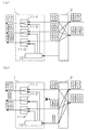
図14は、PON(Passive Optical Network)システムのシステム構成図であり、PONシステムは、加入者宅に設置する複数のONU7(Optical Network Unit)と、局側に設置し、複数のONU7を収容する光終端装置5とを有し、光終端装置5は、レイヤ2スイッチといったノード装置6と接続している。
FIG. 14 is a system configuration diagram of a PON (Passive Optical Network) system. The PON system includes a plurality of ONUs 7 (Optical Network Units) installed in a subscriber's house and a plurality of ONUs 7 installed on a station side. The optical termination device 5 is connected to a node device 6 such as a
図14に示す様に、光終端装置5は、複数のOSU(Optical Subscriber Unit)部51を備えている。1つのOSU部51は、光終端装置5に対して挿抜可能な、通常、パッケージやカード等と呼ばれる1つ以上のハードウェアで構成されており、光終端装置5は、OSU部51を単位として増設が可能である。
As shown in FIG. 14, the optical termination device 5 includes a plurality of OSU (Optical Subscriber Unit)
各OSU部51は、ONU7から受信する光信号を電気信号に変換した後に、受信するフレームに対して必要な処理を行い、再度、光信号に変換してノード装置6に送信し、同様に、ノード装置6から受信する光信号を電気信号に変換した後に、受信するフレームに対して必要な処理を行い、再度、光信号に変換してONU7に送信を行う。
Each
また、図14に示す様に、ノード装置6は、光終端装置側インタフェース部61と、レイヤ2スイッチ部62と、ネットワーク側インタフェース部63とを備えている。光終端装置側インタフェース部61は、光終端装置5と信号を送受信するために必要な処理を行い、ネットワーク側インタフェース部63は、ネットワークと信号を送受信するために必要な処理を行い、レイヤ2スイッチ部62は、フレームを宛先に応じた光リンクから出力する様に、フレームのスイッチングを行う機能を有している。なお、光終端装置側インタフェース部61と、ネットワーク側インタフェース部63は、ノード装置6に対して挿抜可能な、通常、パッケージやカード等と呼ばれる1つ以上のハードウェアで構成されている。
As shown in FIG. 14, the node device 6 includes an optical termination device
図14に示す構成には、冗長系が存在せず、よって、OSU部51や、光終端装置側インタフェース部61や、OSU部51と光終端装置側インタフェース部61を接続する光リンクに障害が発生した場合、障害が回復するまでサービス断が継続する。よって、サービスの信頼性や保守運用性の観点から冗長化が求められる。
In the configuration shown in FIG. 14, there is no redundant system. Therefore, there is a failure in the
このため、光終端装置5と、ノード装置6の通信区間を冗長化した構成が提案されている(例えば、特許文献1、非特許文献1、非特許文献2及び非特許文献3、参照。)。図15は、従来技術による切替構成図である。図15に記載の構成において、図14のOSU部51は、複数のONU7とフレームを送受するために必要な処理を行う部分(図15において、ONU側IF部として表示)と、ノード装置6とフレームを送受するために必要な処理を行う部分(図15において、ノード側IF部として表示)に分割され、ONU側IF部とノード側IF部の間に、ノード装置6のレイヤ2スイッチ部62と同等の機能を有するレイヤ2スイッチ部を設けている。
For this reason, the structure which made the communication area of the optical terminal device 5 and the node apparatus 6 redundant is proposed (for example, refer patent document 1, nonpatent literature 1,
図15に示す構成においては、光終端装置5とノード装置6の両レイヤ2スイッチ部間が冗長化されており、切替えはレイヤ2スイッチ部により行われる。なお、WA及びWBとして表示されているノード側IF部を経由する経路が現用リンクであり、PA及びPBとして表示されているノード側IF部を経由する経路が予備リンクであり、WAを経由する現用リンクが障害となった場合、PAを経由する予備リンクが使用され、WBを経由する現用リンクが障害となった場合、PBを経由する予備リンクが使用される。
In the configuration shown in FIG. 15, the
図15に示す構成においては、非特許文献2や非特許文献3に記載されている、受信端切替方式(1+1切替方式)、送受信端切替方式(1:1切替方式)、送信端切替方式(Link Aggregation)が利用可能である。1+1切替方式とは、送信側のレイヤ2スイッチ部において現用リンクと予備リンクの両方に同じフレームを送信しておき、受信側のレイヤ2スイッチ部においていずれかのリンクからのフレームを選択する方式である。
In the configuration shown in FIG. 15, the reception end switching method (1 + 1 switching method), the transmission / reception end switching method (1: 1 switching method), the transmission end switching method (described in
また、1:1切替方式とは、通常時、送信側のレイヤ2スイッチ部は、現用リンクのみにフレームを送信し、現用リンクに障害が発生した場合にのみ、予備リンクにもフレームを送信する方式である。本方式においては、受信側のレイヤ2スイッチ部と、送信側のレイヤ2スイッチ部は、連動する必要があるため、光終端装置5とノード装置6との間で、切替のための制御信号を送受信する必要がある。このため、制御信号を送受信する必要のない1+1切替方式より装置構成が複雑となるが、通常時に、低優先クラスのフレームを、予備リンクを使用して送受信することができ、また、複数の現用リンクで1つの予備リンクを共用することも可能であり、よって、トラヒックを効率的に収容できる。さらに、Link Aggregationとは、現用リンクと予備リンクの両方から受信するフレームを共に選択する様に受信側のレイヤ2スイッチ部を構成しておき、送信側のレイヤ2スイッチ部が、いずれかのリンクにフレームを送信するものである。
In the 1: 1 switching method, the
なお、フレームのオーバーヘッド、つまり管理情報には、各ユーザのトラフィックを識別するVLAN(Virtual LAN)タグが含まれており、ユーザトラフィック単位、つまり、VLAN単位で切替制御が行われる。 The frame overhead, that is, management information includes a VLAN (Virtual LAN) tag for identifying the traffic of each user, and switching control is performed in units of user traffic, that is, in units of VLAN.
従来技術における構成は、光終端装置5にも、レイヤ2スイッチ部を設けるものであるが、任意のポート間で、フレームのフォワーディング及びスイッチングを行うレイヤ2スイッチ部は高価であり、これを光終端装置5にも実装することは不経済である。一方、コストを上昇させずに切替えを行うためには、2つのポート間で信号を切り替えるポートベースのスイッチを使用すれば良いが、ポート単位の切替え制御しかできなくなるため、複数の現用リンクで1本の予備リンクを共用することができない。よって、複数の現用リンクが同時に障害となった場合に、各現用リンクに収容されている高優先のトラフィックを、1本の予備リンクで救済するといった構成を実現することはできない。
The configuration in the prior art is that the optical termination device 5 is also provided with a
したがって、本発明は、光終端装置に高価なレイヤ2スイッチ部を使用しない、通信システム及び切替方法を提供することを目的とする。さらに、複数の現用リンクで1本の予備リンクを共用し、高優先クラスのフレームのみを選択して救済することができる通信システム及び切替方法を提供することを目的とする。
Accordingly, an object of the present invention is to provide a communication system and a switching method that do not use an
本発明における通信システムによれば、
第1の通信装置と、任意の2つのリンク間でフレームのスイッチングを行う第2の通信装置とを含み、前記第1の通信装置と前記第2の通信装置が、1つ以上の現用リンクと1つの予備リンクで接続された通信システムであって、前記第1の通信装置は、各現用リンクに対応する第1の手段と、予備リンクに対応する多重手段を備えており、前記第1の通信装置から前記第2の通信装置への方向において、前記第1の手段は、第2の通信装置に送信するフレームを、対応する現用リンクのみに送信する構成と、予備リンクのみに送信する構成と、対応する現用リンク及び予備リンクの両方に送信する構成のいずれかに設定することができ、前記多重手段は、各第1の手段が予備リンクに送信するために出力したフレームを多重化して予備リンクに送信することを特徴とする。
According to the communication system of the present invention,
A first communication device, and a second communication device that performs frame switching between any two links, wherein the first communication device and the second communication device include one or more active links In the communication system connected by one spare link, the first communication device includes first means corresponding to each active link and multiplexing means corresponding to the spare link, In the direction from the communication device to the second communication device, the first means transmits a frame to be transmitted to the second communication device only to the corresponding working link and a configuration to transmit only to the backup link. And a corresponding transmission link to both the working link and the protection link, and the multiplexing means multiplexes the frames output by each first means for transmission to the protection link. Reserve phosphorus And transmits to.
本発明における通信システムの他の実施形態によれば、
各フレームに含まれる管理情報には優先度が設定され、前記第1の通信装置は、各第1の手段が予備リンクに送信するために出力したフレームのうち、優先度が所定値以下のフレームを廃棄するフィルタ手段をさらに備えていることも好ましい。
According to another embodiment of the communication system in the present invention,
A priority is set for the management information included in each frame, and the first communication device has a frame whose priority is equal to or lower than a predetermined value among frames output by each first means for transmission to the protection link. It is also preferable to further include filter means for discarding.
また、本発明における通信システムの他の実施形態によれば、
前記第1の通信装置は、予備リンクから受信するフレームに含まれる管理情報に基づき、該フレームの出力先の第1の手段を判定する第2の手段をさらに備えており、前記第2の通信装置から前記第1の通信装置への方向において、前記第1の手段は、対応する現用リンクから受信するフレームのみを選択して出力する構成と、予備リンクから受信するフレームのみを選択して出力する構成と、対応する現用リンク及び予備リンクの両方から受信するフレームを共に選択して出力する構成のいずれかに設定することができることも好ましい。
According to another embodiment of the communication system of the present invention,
The first communication device further includes second means for determining a first means of an output destination of the frame based on management information included in a frame received from the backup link, and the second communication In the direction from the device to the first communication device, the first means selects and outputs only the frame received from the corresponding working link, and selects and outputs only the frame received from the backup link. It is also preferable that it can be set to either a configuration for selecting and outputting a frame received from both the corresponding working link and the protection link.
さらに、本発明における通信システムの他の実施形態によれば、
前記第2の通信装置は、優先度が所定値より高いフレームのみを予備リンクにスイッチングするか、予備リンクにスイッチングしたフレームのうち、優先度が所定値以下のフレームを予備リンクへの送信前に廃棄するフィルタ手段を有していることも好ましい。
Furthermore, according to another embodiment of the communication system of the present invention,
The second communication device switches only frames whose priority is higher than a predetermined value to the protection link, or, among frames switched to the protection link, transmits a frame having a priority lower than the predetermined value before transmission to the protection link. It is also preferable to have a filter means for discarding.
さらに、本発明における通信システムの他の実施形態によれば、
前記第2の通信装置は、前記第1の通信装置に送信する各フレームの管理情報に識別子を追加する手段をさらに備えており、前記第2の手段は、予備リンクから受信したフレームを出力する第1の手段の判定に、前記識別子を使用することも好ましい。
Furthermore, according to another embodiment of the communication system of the present invention,
The second communication apparatus further includes means for adding an identifier to the management information of each frame transmitted to the first communication apparatus, and the second means outputs a frame received from a backup link. It is also preferable to use the identifier for the determination of the first means.
本発明における方法によれば、
第1の通信装置と、任意の2つのリンク間でフレームのスイッチングを行う第2の通信装置とを含み、前記第1の通信装置と前記第2の通信装置が、1つ以上の現用リンクと1つの予備リンクで接続された通信システムにおける、現用リンク障害時の切替方法であって、前記第1の通信装置は、各現用リンクに対応する切替部を備えており、前記第1の通信装置から前記第2の通信装置への方向において、各切替部は、第2の通信装置に送信するフレームを、対応する現用リンクに至る第1のポートのみに出力する第1の構成と、予備リンクに至る第2のポートのみに出力する第2の構成と、第1のポート及び第2のポートの両方に出力する第3の構成のいずれかに設定でき、各切替部は、予備リンクを使用する場合には前記第2の構成又は前記第3の構成に、それ以外の場合には前記第1の構成又は前記第3の構成に設定されることを特徴とする。
According to the method of the present invention,
A first communication device, and a second communication device that performs frame switching between any two links, wherein the first communication device and the second communication device include one or more active links A switching method in the case of a working link failure in a communication system connected by one backup link, wherein the first communication device includes a switching unit corresponding to each working link, and the first communication device In the direction from the second communication device to the second communication device, each switching unit outputs a frame to be transmitted to the second communication device only to the first port reaching the corresponding working link, and a spare link. Can be set to either the second configuration that outputs only to the second port leading to, or the third configuration that outputs to both the first port and the second port, and each switching unit uses a spare link If so, the second configuration or Serial to the third configuration, otherwise, characterized in that it is set to the first configuration or the third configuration.
本発明における方法の他の実施形態によれば、
各フレームに含まれる管理情報には優先度が設定され、前記第1の通信装置は、前記第2の構成又は前記第3の構成において、前記第2のポートに出力されたフレームのうち、優先度が所定値以下のフレームを廃棄し、残りのフレームを予備リンクに送信することも好ましい。
According to another embodiment of the method in the present invention,
A priority is set for the management information included in each frame, and the first communication device has a priority among frames output to the second port in the second configuration or the third configuration. It is also preferable to discard frames whose degrees are below a predetermined value and transmit the remaining frames to the protection link.
また、本発明における方法の他の実施形態によれば、
前記第1の通信装置は、予備リンクから受信するフレームに含まれる管理情報に基づき、該フレームに対応する現用リンクを判定し、判定した現用リンクに対応する切替部に該フレームを出力し、前記第2の通信装置から前記第1の通信装置への方向において、各切替部は、対応する現用リンクに至る第3のポートから受信するフレームのみを、送信先である第5のポートに出力する第4の構成と、予備リンクに至る第4のポートから受信するフレームのみを前記第5のポートに出力する第5の構成と、前記第3のポート及び前記第4のポートから受信するフレームを共に前記第5のポートに出力する第6の構成のいずれかに設定することができ、各切替部は、予備リンクを使用する場合には前記第5の構成又は前記第6の構成に、それ以外の場合には前記第4の構成又は前記第6の構成に設定され、前記第2の通信装置は、前記予備リンクを使用している場合には、現用リンクに送信するフレームを前記予備リンクに送信することも好ましい。
Also, according to another embodiment of the method in the present invention,
The first communication device determines a working link corresponding to the frame based on management information included in a frame received from a backup link, and outputs the frame to a switching unit corresponding to the determined working link, In the direction from the second communication device to the first communication device, each switching unit outputs only the frame received from the third port reaching the corresponding working link to the fifth port that is the transmission destination. A fourth configuration, a fifth configuration for outputting only frames received from the fourth port reaching the backup link to the fifth port, and frames received from the third port and the fourth port. Both can be set to any of the sixth configurations that output to the fifth port, and each switching unit can be set to the fifth configuration or the sixth configuration when using a spare link. Except In this case, the second communication device is set to the fourth configuration or the sixth configuration, and when the spare communication link is used, the second communication device transmits a frame to be transmitted to the working link to the spare link. It is also preferable to do.
さらに、本発明における方法の他の実施形態によれば、
前記第2の通信装置は、優先度が所定値より高いフレームのみを予備リンクにスイッチングするか、予備リンクにスイッチングしたフレームのうち、優先度が所定値以下のフレームを予備リンクへの送信前に廃棄することも好ましい。
Furthermore, according to another embodiment of the method in the present invention,
The second communication device switches only frames whose priority is higher than a predetermined value to the protection link, or, among frames switched to the protection link, transmits a frame having a priority lower than the predetermined value before transmission to the protection link. It is also preferable to discard.
さらに、本発明における方法の他の実施形態によれば、
前記第1の通信装置は、前記第2の通信装置に送信する各フレームの管理情報に第1の識別子を追加し、前記第2の通信装置は、予備リンクから受信したフレームに対応する現用リンクの判定に前記第1の識別子を使用し、前記第2の通信装置は、前記第1の通信装置に送信する各フレームの管理情報に第2の識別子を追加し、前記第1の通信装置は、予備リンクから受信したフレームに対応する現用リンクの判定に前記第2の識別子を使用することも好ましい。
Furthermore, according to another embodiment of the method in the present invention,
The first communication device adds a first identifier to the management information of each frame transmitted to the second communication device, and the second communication device uses the working link corresponding to the frame received from the backup link. The second identifier is added to the management information of each frame to be transmitted to the first communication device, and the first communication device It is also preferable to use the second identifier for determining the working link corresponding to the frame received from the protection link.
第1の通信装置は、小型のポートベースの切替を行う第1の手段と、フレームベースの多重を行う多重手段のみを使用し、任意のポート間においてフレームのフォワーディング及びスイッチングが可能な、高機能で単一大容量のレイヤ2スイッチを使用しないため経済的である。また、本発明においては、複数の現用リンクが同時に障害となったとしても、これら複数の現用リンクで送受信されている高優先クラスのトラヒックを、1本の予備リンクで救済することができ低価格で信頼性を向上させることが可能である。
The first communication device uses only the first means for performing small port-based switching and the multiplexing means for performing frame-based multiplexing, and is capable of forwarding and switching frames between arbitrary ports. This is economical because a single large-
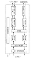
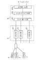
本発明を実施するための形態について、以下では図面を用いて詳細に説明する。図1は、本発明による通信システムの構成図である。通信システムは、PONシステムにおいて、局側に設置する装置である光終端装置1と、レイヤ2スイッチといったノード装置2とを有しており、光終端装置1とノード装置2は、1つ以上の現用リンクと1つの予備リンクで接続されている。
EMBODIMENT OF THE INVENTION The form for implementing this invention is demonstrated in detail below using drawing. FIG. 1 is a block diagram of a communication system according to the present invention. The communication system includes, in the PON system, an optical termination device 1 which is a device installed on the station side, and a
図1に示す様に、光終端装置1は、複数のOSU部11と、多重分離部12を備えている。なお、1つのOSU部11は、光終端装置1に対して挿抜可能な、通常、パッケージやカード等と呼ばれる1つ以上のハードウェアで構成されている。OSU部11は、ONU側の光リンクからPONシステムの規格に沿った信号を受信し、所定の処理を行った後、各フレームをノード装置2側の光リンク、つまり現用リンクに送信し、また、ノード装置2側の光リンクから受信するフレームを含む信号に対して所定の処理を行った後、PONシステムの規格に沿った信号を生成して、ONU側の光リンクから送信する。なお、図1に示す構成において、各OSU部11は、ONU側とノード装置2側それぞれに対して1対の光信号の送受信を行う機能を提供しているが、提供するリンク数は任意である。
As shown in FIG. 1, the optical termination device 1 includes a plurality of
図2は、OSU部11のブロック図である。PON終端部は、PONシステムの規格に沿った信号を生成して第1光送受信部に出力し、第1光送受信部から入力されるPONシステムの規格に沿った信号からフレームを取り出す機能を有し、第1光送受信部は、PONシステムの規格に沿った光信号を送受信する。識別子付与部は、切替え区間において各フレームを識別するための識別子を、フレームのオーバーヘッド、つまり、管理情報に付与して切替部に出力し、識別子除去部は、切替え区間において各フレームを識別するための前記識別子をフレームの管理情報から除去する。
FIG. 2 is a block diagram of the
切替部は、ポート単位で切替えを行う機能を有する。具体的には、ノード装置2への送信方向においては、識別子付与部から入力される総てのフレームを、第1フレーム処理部への第1のポートのみに出力する構成、第2フレーム処理部への第2のポートのみに出力する構成、第1フレーム処理部及び第2フレーム処理部への両ポートに共に出力する構成のいずれかの構成に設定することが可能である。また、ノード装置2から受信する方向においては、第1フレーム処理部に接続する第3のポートから入力されるフレームのみを選択して、識別子除去部と接続する第5のポートに出力する構成、第2フレーム処理部に接続する第4のポートから入力されるフレームのみを選択して第5のポートに出力する構成、第3のポート及び第4のポートから入力されるフレームを共に選択して第5のポートに出力する構成の、いずれかの構成に設定することが可能である。切替制御部は、切替動作の開始トリガとなる障害情報の収集や、切替部の切替え処理等の制御を行う。
The switching unit has a function of switching on a port basis. Specifically, in the transmission direction to the
第1及び第2フレーム処理部は、それぞれ、ノード装置2と送受信するフレームに必要な処理を行う。なお、第1フレーム処理部は、現用リンクで送受信されるフレームを処理し、第2フレーム処理部は、予備リンクで送受信されるフレームを処理するものであり、第2光送受信部は、ノード装置2に接続する現用リンクとの間で光信号の送受信を行う。また、フィルタ部は、優先度の高いフレームのみを通過させ、優先度の低いフレームを廃棄する機能を有する。なお、優先度の高低は、フレームの管理情報に含まれるCoS(Class of Service)値で判別可能である。なお、本実施形態において、優先度は、高又は低の2段階であるが、優先度として複数の段階を使用している場合には、所定の段階以下の優先度を低、それ以外の優先度を高として本発明を適用する。
The first and second frame processing units each perform processing necessary for a frame transmitted / received to / from the
なお、切替え区間において各フレームを識別するための識別子としては、例えば、IEEE802.1adで規定されるSタグを使用することができる。具体的には、識別子付与部は、図6に示すフレームに対してSタグを追加して図7に示すフレームを出力し、識別子除去部は、図7に示すフレームからSタグを除去して図6に示すフレームを出力する。なお、図6及び7におけるCタグがVLANタグである。 Note that, as an identifier for identifying each frame in the switching section, for example, an S tag defined by IEEE 802.1ad can be used. Specifically, the identifier adding unit adds an S tag to the frame shown in FIG. 6 and outputs the frame shown in FIG. 7, and the identifier removing unit removes the S tag from the frame shown in FIG. The frame shown in FIG. 6 is output. The C tag in FIGS. 6 and 7 is a VLAN tag.
現用リンクが異なれば、異なるユーザトラフィックに対して、同じ値をVLANタグに使用可能であるが、異なる現用リンクに収容されている同一VLANタグ値を使用するフレームを、1本の予備リンクで救済を行う場合、VLANの識別、つまり、ユーザトラフィックの識別ができなくなる。このため、本発明においては、切替え区間において識別子を付与し、各VLANを識別する。したがって、ある予備リンクを使用する総ての現用リンクにおいて、VLANタグの値が重複しない等、受信するフレームのVLANタグや、その他の値から、個々のフレームが属するユーザトラフィックを識別可能である場合には、識別子を付与する必要はなく、この場合には、識別子付与部及び識別子除去部は不要である。 If the working link is different, the same value can be used for the VLAN tag for different user traffic, but a frame using the same VLAN tag value accommodated in a different working link is relieved with one spare link. In this case, VLAN identification, that is, user traffic cannot be identified. For this reason, in the present invention, an identifier is assigned in the switching section to identify each VLAN. Therefore, the user traffic to which each frame belongs can be identified from the VLAN tag of the received frame and other values such as the VLAN tag value is not duplicated in all working links using a certain protection link. It is not necessary to assign an identifier to the ID, and in this case, an identifier assigning unit and an identifier removing unit are unnecessary.
図3は、多重分離部12のブロック図である。図3において、多重処理部は、各OSU部11からのフレームを多重して出力し、分離処理部は、第3光送受信部からフレームを受信し、そのフレームを出力すべきOSU部11を、フレームのVLANを特定する値、例えば、VLANタグの値、あるいは、VLANタグの値及び識別子に基づき判定し、判定したOSU部11に出力する。また、第3光送受信部は、ノード装置2に接続する予備リンクとの間で光信号の送受信を行う。
FIG. 3 is a block diagram of the
図1に戻り、ノード装置2は、光終端装置側インタフェース部21と、レイヤ2スイッチ部22と、ネットワーク側インタフェース部23と、切替制御部24とを備えている。なお、光終端装置側インタフェース部21及びネットワーク側インタフェース部23は、通常、パッケージやカード等と呼ばれる1つ以上のハードウェアで構成されている。また、1つの光終端装置側インタフェース部21や、ネットワーク側インタフェース部23が収容するリンク数は任意である。
Returning to FIG. 1, the
図4は、光終端装置側インタフェース部21のブロック図である。第4光送受信部は、光終端装置1との間で光信号を送受信し、フレーム処理部は、光終端装置1と送受信するフレームに必要な処理を行い、キューマネージャ部は、バッファを有し、レイヤ2スイッチ22側と、光終端装置1側の伝送速度差を吸収するものである。また、フィルタ部は、予備リンクを収容する光終端装置側インタフェース部21のみに実装され、優先度の高いフレームのみを通過させ、優先度の低いフレームを廃棄する機能を有する。なお、フィルタ機能の実行を行うか否かを制御できるフィルタ部を、総ての、光終端装置側インタフェース部21に実装しておき、収容しているリンクが現用であるか否かに応じて、フィルタ機能の実行を制御する構成であっても良い。また、レイヤ2スイッチ部22が、優先度を認識し、高優先クラスのフレームのみを予備リンクに切り替えできる場合には、フィルタ部は省略できる。
FIG. 4 is a block diagram of the optical termination device
図5は、ネットワーク側インタフェース部23のブロック図である。キューマネージャ部は、バッファを有し、レイヤ2スイッチ22側と、ネットワーク側の伝送速度差を吸収するものであり、フレーム処理部は、ネットワークと送受信するフレームに必要な処理を行い、第5光送受信部は、ネットワークとの間で光信号を送受信するものである。また、識別子除去部及び識別子付与部は、OSU部11内のものと同じく、切替え区間において各フレームがいずれのVLANに属するのかを識別するための識別子を管理情報に付与及び除去する。つまり、予備リンクを使用して送受信されるフレームが、本来、送受信されるべき現用リンクを特定するための識別子を管理情報に付与及び除去する。なお、識別子を付与しなくとも、予備リンクから受信したフレームに対応する現用リンクを判定可能である場合には、OSU部11に関して既に説明した様に、識別子除去部及び識別子付与部は必要ではない。
FIG. 5 is a block diagram of the network
なお、レイヤ2スイッチ部22は、ノード装置2が実装する任意のリンク間でフレームのスイッチングを行うためのもの、つまり、あるリンクに入力されるフレームを、宛先に対応するリンクから送信する様にスイッチングを行うものである。なお、予備リンクに送信するフレームについては、現用リンクと同時に送信すること、つまり、同じフレームを複製して、2つのリンクに同時に送信することが可能なものである。また、切替制御部24は、予備リンクの切替えのために、必要な障害情報の収集と各部の制御を行う。
The
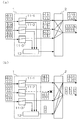
続いて、図8から図13を用いて具体的な切替動作について説明する。なお、以下の説明においては、1本の予備リンクを3本の現用リンクが共用するものとし、OSU部11−1を通過するものを第1現用リンクと、OSU部11−2を通過するものを第2現用リンクと、OSU部11−3を通過するものを第3現用リンクと呼ぶものとする。なお、予備リンクは、多重分離部12に接続されるリンクである。また、光終端装置1からノード装置2への方向を上り方向と、ノード装置2から光終端装置1への方向を下り方向と呼ぶものとする。さらに、図8から図13において、L1及びH1は、それぞれ、第1現用リンクを使用する低優先度及び高優先度のフレームであり、L2及びH2は、それぞれ、第2現用リンクを使用する低優先度及び高優先度のフレームであり、L3及びH3は、第3現用リンクを使用する低優先度及び高優先度のフレームである。
Next, a specific switching operation will be described with reference to FIGS. In the following description, it is assumed that one working link is shared by three working links, and one that passes through the OSU unit 11-1 passes through the first working link and the OSU unit 11-2. Is called the second working link, and the one passing through the OSU unit 11-3 is called the third working link. Note that the backup link is a link connected to the
図8及び図9は、送受信端切替方式での動作を説明する図であり、図8は上り方向の動作を、図9は下り方向の動作を示している。図8(a)は、通常時、つまり、障害が発生していない場合の上り方向の状態であり、各OSU部11−1〜11−3の切替部は、入力されるフレームを、それぞれ、図2の第1フレーム処理部側に、つまり、現用リンク側に出力する。したがって、各OSU部11−1〜11−3に入力された各フレームは、そのまま現用リンクに送信され、それらフレームは、ノード装置2のレイヤ2スイッチ部22にてスイッチングされて、所定のネットワーク側リンクから送信される。
8 and 9 are diagrams for explaining the operation in the transmission / reception end switching method. FIG. 8 shows the operation in the upstream direction, and FIG. 9 shows the operation in the downstream direction. FIG. 8 (a) shows a state in the uplink direction during normal operation, that is, when no failure has occurred, and the switching units of the OSU units 11-1 to 11-3 The data is output to the first frame processing unit side in FIG. 2, that is, to the working link side. Accordingly, the frames input to the OSU units 11-1 to 11-3 are transmitted to the working link as they are, and the frames are switched by the
この状態において、第2現用リンクに障害が発生した場合、図8(b)に示す様に、OSU部11−2の切替部は、入力されるフレームの出力先を、図2の第2フレーム処理部側に切替を行う。第2フレーム処理部に出力されたフレームの内、低優先度のフレームは、フィルタ部で除去されるため、多重分離部12は、高優先度のフレームのみを予備リンクに送信する。また、障害発生により、ノード装置2のレイヤ2スイッチ部22は、第2現用リンクから受信しているフレームについては、予備リンクから受信する様に、スイッチング処理をVLAN単位で変更し、これにより、高優先度のトラフィクが救済される。なお、図8(b)において、OSU部11−2の切替部は、予備リンク側のみにフレームを送信しているが、現用リンクと予備リンクの両方にフレームを送信する構成であっても良い。
In this state, when a failure occurs in the second working link, as shown in FIG. 8B, the switching unit of the OSU unit 11-2 determines the output destination of the input frame as the second frame in FIG. Switch to the processing unit side. Of the frames output to the second frame processing unit, the low priority frame is removed by the filter unit, so the
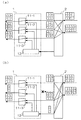
図9(a)は、通常時の下り方向の状態であり、各OSU部11−1〜11−3の切替部は、第1フレーム処理部を選択し、よって、現用リンクから入力されるフレームがONU側に出力される。この状態において、第2現用リンクに障害が発生した場合、図9(b)に示す様に、ノード装置2のレイヤ2スイッチ部22は、第2現用リンクから送信されるフレームについては、予備リンクから送信される様に、VLAN単位で切替えを行う。ただし、予備リンクに接続する光終端装置側インタフェース部21には、フィルタ部が実装されているので、予備リンクには、高優先度のフレームのみが送信される。多重分離部12は、受信したフレームの管理情報に基づき受信したフレームの出力先がOSU部11−2であることを判定し、受信フレームをOSU部11−2に出力する。OSU部11−2の切替部は、第2現用リンクの障害発生に伴い、第2フレーム処理部を選択し、よって、高優先度のトラフィックが救済される。なお、既に述べた様に、ノード装置2のレイヤ2スイッチ部22が、高優先クラスのフレームのみを予備リンクへ送信する様にVLAN単位で切替えを行い、光終端装置側インタフェース部21のフィルタ部を省略する形態であっても良い。さらに、図9(b)においては、ノード装置2は、予備リンク側のみにフレームを送信しているが、第2現用リンクと予備リンクの両方にフレームを送信する構成であっても良い。
FIG. 9A shows a normal state in the downlink direction, and the switching unit of each OSU unit 11-1 to 11-3 selects the first frame processing unit, and thus the frame input from the working link. Is output to the ONU side. In this state, when a failure occurs in the second working link, as shown in FIG. 9B, the
なお、本方式においては、光終端装置1とノード装置2間で、切替え制御のための制御情報を送受信する必要がある。この制御情報の送受信は、例えば、予備リンクを使用し、切替原因や、切替対象のVLANを特定する値を交換する。ここで、切替原因とは、例えば、信号断、信号劣化、強制切替、手動切替等であり、切替対象のVLANを特定する値とは、VLANタグの値、さらに、識別子を使用している場合には、VLANタグの値と識別子の組合せを含む値である。なお、制御情報は、予備リンク以外の制御線を利用して交換する形態であっても良い。
In this method, it is necessary to transmit and receive control information for switching control between the optical terminal device 1 and the
図10及び図11は、送信端切替方式での動作を説明する図であり、図10は上り方向の動作を、図11は下り方向の動作を示している。なお、以後の説明においては1:1切替方式と共通する部分については説明を省略する。図10(a)は、通常時の上り方向の状態であり、各OSU部11−1〜11−3の切替部は、入力されるフレームを、それぞれ、図2の第1フレーム処理部側に、つまり、現用リンク側に出力する。したがって、各OSU部11−1〜11−3に入力された各フレームは、そのまま現用リンクに送信される。また、ノード装置2は、現用リンクから受信するフレームのみならず、予備リンクから受信するフレームについても、VLANを特定する値に基づき、所定のネットワーク側リンクへ送信される様に、レイヤ2スイッチ部22を構成しておく。
10 and 11 are diagrams for explaining the operation in the transmission end switching method. FIG. 10 shows the operation in the upstream direction, and FIG. 11 shows the operation in the downstream direction. In the following description, description of portions common to the 1: 1 switching method is omitted. FIG. 10A shows a normal uplink state, and the switching units of the OSU units 11-1 to 11-3 transfer the input frames to the first frame processing unit side in FIG. That is, it outputs to the working link side. Accordingly, the frames input to the OSU units 11-1 to 11-3 are transmitted as they are to the working link. Further, the
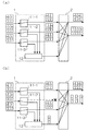
この状態において、第2現用リンクに障害が発生した場合、図10(b)に示す様に、OSU部11−2の切替部は、入力されるフレームの出力先を、図2の第2フレーム処理部側に切替を行う。第2フレーム処理部に出力されたフレームの内、低優先度のフレームは、フィルタ部で除去されるため、多重分離部12は、高優先度のフレームのみを予備リンクに送信する。ノード装置2のレイヤ2スイッチ部22は、あらかじめ、予備リンクから受信するフレームについても、VLANを特定する値に基づき、所定のネットワーク側ポートへ送信される様に構成されているため、光終端装置1側の処理のみで高優先度のトラフィクが救済される。
In this state, when a failure occurs in the second working link, as shown in FIG. 10B, the switching unit of the OSU unit 11-2 determines the output destination of the input frame as the second frame in FIG. Switch to the processing unit side. Of the frames output to the second frame processing unit, the low priority frame is removed by the filter unit, so the
また、図11(a)は、通常時の下り方向の状態であり、各OSU部11−1〜11−3の切替部は、第1及び第2フレーム処理部の両方を選択して出力している。この状態において、第2現用リンクに障害が発生した場合、図11(b)に示す様に、ノード装置2のレイヤ2スイッチ部22は、第2現用リンクへ送信しているフレームについては、予備リンクへ送信する様に、VLAN単位で切替えを行う。これにより、図9を用いて説明したのと同じく、予備リンクには、高優先度のフレームのみが送信される。多重分離部12は、管理情報に含まれる値、例えば、識別子を使用している場合には識別子の値に基づき受信したフレームを、OSU部11−2に出力し、よって、光終端装置1側においては、特別な処理を行うことなく高優先度のトラフィックが救済される。以上、本形態においては、制御情報の送受信を省略することが可能である。
Further, FIG. 11A shows a normal state in the downward direction, and the switching unit of each OSU unit 11-1 to 11-3 selects and outputs both the first and second frame processing units. ing. In this state, when a failure occurs in the second working link, as shown in FIG. 11B, the
図12及び図13は、受信端切替方式での動作を説明する図であり、図12は上り方向の動作を、図13は下り方向の動作を示している。図12(a)は、通常時の上り方向の状態であり、各OSU部11−1〜11−3の切替部は、入力されるフレームを、それぞれ、図2の第1及び第2フレーム処理部の両方に出力する。したがって、各OSU部11−1〜11−3に入力された各フレームは、そのまま現用リンクに送信されると共に、高優先フレームについては、予備リンクにも送信されることになる。ただし、ノード装置2は、現用リンクからのフレームのみをスイッチングし、予備リンクからのフレームを廃棄する。
12 and 13 are diagrams for explaining the operation in the receiving end switching method. FIG. 12 shows the operation in the upstream direction, and FIG. 13 shows the operation in the downstream direction. FIG. 12A shows a normal state in the upward direction, and the switching units of the OSU units 11-1 to 11-3 process the input frames respectively in the first and second frame processes of FIG. Output to both. Therefore, each frame input to each of the OSU units 11-1 to 11-3 is transmitted as it is to the working link, and a high priority frame is also transmitted to the backup link. However, the
この状態において、第2現用リンクに障害が発生した場合、図12(b)に示す様に、ノード装置2のレイヤ2スイッチ部22は、第2現用リンクから受信しているフレームについては、予備リンクから受信する様に、スイッチング構成を変更する。
In this state, when a failure occurs in the second working link, as shown in FIG. 12B, the
また、図13(a)は、通常時の下り方向の状態であり、ノード装置2は、第1現用リンクから第3現用リンクに送信するフレームについては、予備リンクにも送信する様に、レイヤ2スイッチ部22を構成する。フィルタ部におけるフィルタ処理により、あるいは、予備リンクには優先度の高いフレームのみをスイッチングすることにより、予備リンクには、第1現用リンクから第3現用リンクに送信されている優先度の高いフレームと同じフレームが送信され、これらは、それぞれ、対応するOSU部の第2フレーム処理部から切替部に出力される。ただし、各OSU部11−1〜11−3の切替部は、第1フレーム処理部を選択しているので、現用リンクから入力されるフレームが、ONU側に出力される。この状態において、第2現用リンクに障害が発生した場合、図13(b)に示す様に、OSU部11−2の切替部は、第2フレーム処理部を選択する様に切替えを行い、よって、高優先度のトラフィックが救済される。
FIG. 13 (a) shows a normal state in the downlink direction, and the
本発明においては、任意ポート間においてフレームのフォワーディング及びスイッチングが可能な、高機能で単一大容量のレイヤ2スイッチ部を光終端装置1に使用することなく、小型のポートベースの切替部とフレームベースの多重分離部のみを使用するため経済的である。また、本発明においては、サービスクラス単位での切替制御が可能であり、障害発生時に救済が必要となる高優先クラスのトラヒックに応じて予備リソースを確保すれば良いため経済的である。
In the present invention, a small-capacity port-based switching unit and a frame can be used without using a high-function single large-
1、5 光終端装置
2、6 ノード装置
7 ONU
11、11−1、11−2、11−3、51 OSU部
12 多重分離部
21、61 光終端装置側インタフェース部
22、62 レイヤ2スイッチ部
23、63 ネットワーク側インタフェース部
24 切替制御部
1, 5
11, 11-1, 11-2, 11-3, 51
Claims (10)
前記第1の通信装置は、各現用リンクに対応する第1の手段と、予備リンクに対応する多重手段を備えており、
前記第1の通信装置から前記第2の通信装置への方向において、前記第1の手段は、第2の通信装置に送信するフレームを、対応する現用リンクのみに送信する構成と、予備リンクのみに送信する構成と、対応する現用リンク及び予備リンクの両方に送信する構成のいずれかに設定することができ、
前記多重手段は、各第1の手段が予備リンクに送信するために出力したフレームを多重化して予備リンクに送信する、
通信システム。 A first communication device, and a second communication device that performs frame switching between any two links, wherein the first communication device and the second communication device include one or more active links A communication system connected by one spare link,
The first communication device includes first means corresponding to each working link and multiplexing means corresponding to a backup link,
In the direction from the first communication device to the second communication device, the first means transmits a frame to be transmitted to the second communication device only to the corresponding working link, and only the backup link. Can be set to either the configuration to transmit to the corresponding configuration and the configuration to transmit to both the corresponding working link and protection link,
The multiplexing means multiplexes the frames output by each first means for transmission to the protection link and transmits the multiplexed frames to the protection link.
Communications system.
前記第1の通信装置は、各第1の手段が予備リンクに送信するために出力したフレームのうち、優先度が所定値以下のフレームを廃棄するフィルタ手段をさらに備えている、
請求項1に記載の通信システム。 Priorities are set for the management information included in each frame,
The first communication device further includes filter means for discarding frames having a priority level equal to or lower than a predetermined value among frames output by each first means for transmission to the backup link.
The communication system according to claim 1.
前記第2の通信装置から前記第1の通信装置への方向において、前記第1の手段は、対応する現用リンクから受信するフレームのみを選択して出力する構成と、予備リンクから受信するフレームのみを選択して出力する構成と、対応する現用リンク及び予備リンクの両方から受信するフレームを共に選択して出力する構成のいずれかに設定することができる、
請求項1又は2に記載の通信システム。 The first communication device further includes second means for determining a first means of an output destination of the frame based on management information included in the frame received from the backup link,
In the direction from the second communication device to the first communication device, the first means selects and outputs only the frame received from the corresponding working link, and only the frame received from the backup link. Can be set to either a configuration for selecting and outputting, and a configuration for selecting and outputting frames received from both the corresponding working link and protection link,
The communication system according to claim 1 or 2.
請求項3に記載の通信システム。 The second communication device switches only frames whose priority is higher than a predetermined value to the protection link, or, among frames switched to the protection link, transmits a frame having a priority lower than the predetermined value before transmission to the protection link. Having filter means to discard,
The communication system according to claim 3.
前記第2の手段は、予備リンクから受信したフレームを出力する第1の手段の判定に、前記識別子を使用する、
請求項3又は4に記載の通信システム。 The second communication device further includes means for adding an identifier to management information of each frame to be transmitted to the first communication device,
The second means uses the identifier in the determination of the first means for outputting the frame received from the backup link.
The communication system according to claim 3 or 4.
前記第1の通信装置は、各現用リンクに対応する切替部を備えており、
前記第1の通信装置から前記第2の通信装置への方向において、各切替部は、第2の通信装置に送信するフレームを、対応する現用リンクに至る第1のポートのみに出力する第1の構成と、予備リンクに至る第2のポートのみに出力する第2の構成と、第1のポート及び第2のポートの両方に出力する第3の構成のいずれかに設定でき、各切替部は、予備リンクを使用する場合には前記第2の構成又は前記第3の構成に、それ以外の場合には前記第1の構成又は前記第3の構成に設定される、
切替方法。 A first communication device, and a second communication device that performs frame switching between any two links, wherein the first communication device and the second communication device include one or more active links A switching method at the time of a working link failure in a communication system connected by one spare link,
The first communication device includes a switching unit corresponding to each working link,
In the direction from the first communication device to the second communication device, each switching unit outputs a frame to be transmitted to the second communication device only to the first port reaching the corresponding working link. Each of the switching units, the second configuration that outputs only to the second port that reaches the backup link, and the third configuration that outputs to both the first port and the second port. Is set to the second configuration or the third configuration when a spare link is used, and is set to the first configuration or the third configuration otherwise.
Switching method.
前記第1の通信装置は、前記第2の構成又は前記第3の構成において、前記第2のポートに出力されたフレームのうち、優先度が所定値以下のフレームを廃棄し、残りのフレームを予備リンクに送信する、
請求項6に記載の方法。 Priorities are set for the management information included in each frame,
In the second configuration or the third configuration, the first communication device discards a frame having a priority level equal to or lower than a predetermined value from the frames output to the second port, and uses the remaining frames. Send to backup link,
The method of claim 6.
前記第2の通信装置から前記第1の通信装置への方向において、各切替部は、対応する現用リンクに至る第3のポートから受信するフレームのみを、送信先である第5のポートに出力する第4の構成と、予備リンクに至る第4のポートから受信するフレームのみを前記第5のポートに出力する第5の構成と、前記第3のポート及び前記第4のポートから受信するフレームを共に前記第5のポートに出力する第6の構成のいずれかに設定することができ、各切替部は、予備リンクを使用する場合には前記第5の構成又は前記第6の構成に、それ以外の場合には前記第4の構成又は前記第6の構成に設定され、
前記第2の通信装置は、前記予備リンクを使用している場合には、現用リンクに送信するフレームを前記予備リンクに送信する、
請求項6又は7に記載の方法。 The first communication device determines a working link corresponding to the frame based on management information included in a frame received from a backup link, and outputs the frame to a switching unit corresponding to the determined working link.
In the direction from the second communication device to the first communication device, each switching unit outputs only frames received from the third port reaching the corresponding working link to the fifth port that is the transmission destination. A fourth configuration that outputs only a frame received from the fourth port reaching the backup link to the fifth port, and a frame received from the third port and the fourth port. Can be set to any one of the sixth configurations that output to the fifth port, and each switching unit can be set to the fifth configuration or the sixth configuration when using a spare link, Otherwise, set to the fourth configuration or the sixth configuration,
When the second communication device uses the spare link, the second communication device sends a frame to be transmitted to the working link to the spare link.
The method according to claim 6 or 7.
請求項8に記載の方法。 The second communication device switches only frames whose priority is higher than a predetermined value to the protection link, or, among frames switched to the protection link, transmits a frame having a priority lower than the predetermined value before transmission to the protection link. Discard,
The method of claim 8.
前記第2の通信装置は、前記第1の通信装置に送信する各フレームの管理情報に第2の識別子を追加し、前記第1の通信装置は、予備リンクから受信したフレームに対応する現用リンクの判定に前記第2の識別子を使用する、
請求項8又は9に記載の方法。 The first communication device adds a first identifier to the management information of each frame transmitted to the second communication device, and the second communication device uses the working link corresponding to the frame received from the backup link. Using the first identifier in the determination of
The second communication device adds a second identifier to the management information of each frame transmitted to the first communication device, and the first communication device uses the working link corresponding to the frame received from the backup link. Using the second identifier in the determination of
10. A method according to claim 8 or 9.
Priority Applications (1)
| Application Number | Priority Date | Filing Date | Title |
|---|---|---|---|
| JP2009139932A JP2010288043A (en) | 2009-06-11 | 2009-06-11 | Communication system and switching method in the communication system |
Applications Claiming Priority (1)
| Application Number | Priority Date | Filing Date | Title |
|---|---|---|---|
| JP2009139932A JP2010288043A (en) | 2009-06-11 | 2009-06-11 | Communication system and switching method in the communication system |
Publications (1)
| Publication Number | Publication Date |
|---|---|
| JP2010288043A true JP2010288043A (en) | 2010-12-24 |
Family
ID=43543435
Family Applications (1)
| Application Number | Title | Priority Date | Filing Date |
|---|---|---|---|
| JP2009139932A Pending JP2010288043A (en) | 2009-06-11 | 2009-06-11 | Communication system and switching method in the communication system |
Country Status (1)
| Country | Link |
|---|---|
| JP (1) | JP2010288043A (en) |
Cited By (2)
| Publication number | Priority date | Publication date | Assignee | Title |
|---|---|---|---|---|
| JP2012151660A (en) * | 2011-01-19 | 2012-08-09 | Mitsubishi Electric Corp | Intra-station device and communication system |
| JP7400820B2 (en) | 2019-07-09 | 2023-12-19 | 住友電気工業株式会社 | In-vehicle communication system, in-vehicle device and vehicle communication method |
Citations (1)
| Publication number | Priority date | Publication date | Assignee | Title |
|---|---|---|---|---|
| JP2007060438A (en) * | 2005-08-25 | 2007-03-08 | Nec Corp | Center side device of optical access network and method for transmitting data signal of optical access network |
-
2009
- 2009-06-11 JP JP2009139932A patent/JP2010288043A/en active Pending
Patent Citations (1)
| Publication number | Priority date | Publication date | Assignee | Title |
|---|---|---|---|---|
| JP2007060438A (en) * | 2005-08-25 | 2007-03-08 | Nec Corp | Center side device of optical access network and method for transmitting data signal of optical access network |
Cited By (2)
| Publication number | Priority date | Publication date | Assignee | Title |
|---|---|---|---|---|
| JP2012151660A (en) * | 2011-01-19 | 2012-08-09 | Mitsubishi Electric Corp | Intra-station device and communication system |
| JP7400820B2 (en) | 2019-07-09 | 2023-12-19 | 住友電気工業株式会社 | In-vehicle communication system, in-vehicle device and vehicle communication method |
Similar Documents
| Publication | Publication Date | Title |
|---|---|---|
| JP4562443B2 (en) | Optical transmission system and optical transmission method | |
| CN109150361B (en) | Transmission network system, data exchange and transmission method, device and equipment | |
| US10491487B2 (en) | Network service establishment method, orchestration control center, and network system | |
| JP6269088B2 (en) | Redundant path providing method and transmission apparatus | |
| JP2006166037A (en) | Optical transmission device and its system | |
| US20040085954A1 (en) | Out-of-band signalling apparatus and method for an optical cross connect | |
| JP4759222B2 (en) | Communication method and communication apparatus | |
| JP2008104144A (en) | Packet communication method and packet communication device | |
| JP6361465B2 (en) | Transmission apparatus and redundancy providing method | |
| JP5613633B2 (en) | Node device, communication system, and failure switching method | |
| JP2004253881A (en) | Office line concentrator | |
| US8861956B2 (en) | Apparatus and method for switching paths in a wavelength-multiplexing network | |
| WO2012079328A1 (en) | Switching method and system for multiplex section protection and packet transport network device | |
| EP2077637A1 (en) | System and method for protecting payload information in radio transmission | |
| JP2010288043A (en) | Communication system and switching method in the communication system | |
| JP5357436B2 (en) | Transmission equipment | |
| JP2005012306A (en) | Node device | |
| JP4704311B2 (en) | Communication system and failure recovery method | |
| JP3576477B2 (en) | Path network operation method, path network, and node device | |
| CN106941436B (en) | Message transmission method and device | |
| EP1703677B1 (en) | Access line termination system, access line termination device and transmission control method | |
| KR100742505B1 (en) | A communication equipment of bidirectional using by unidirectional optical transmission router combined with unidirectional optical cross connector and router, and thereof method | |
| JP3551115B2 (en) | Communication network node | |
| JP2017076944A (en) | Optical transmission system, optical transmission method, controlled node, and optical transmission program | |
| JP5368846B2 (en) | Passive optical network (PON) with enhanced protection function and protection method in passive optical network |
Legal Events
| Date | Code | Title | Description |
|---|---|---|---|
| RD03 | Notification of appointment of power of attorney |
Free format text: JAPANESE INTERMEDIATE CODE: A7423 Effective date: 20100929 |
|
| A621 | Written request for application examination |
Free format text: JAPANESE INTERMEDIATE CODE: A621 Effective date: 20111011 |
|
| A977 | Report on retrieval |
Free format text: JAPANESE INTERMEDIATE CODE: A971007 Effective date: 20130104 |
|
| A131 | Notification of reasons for refusal |
Free format text: JAPANESE INTERMEDIATE CODE: A131 Effective date: 20130212 |
|
| RD04 | Notification of resignation of power of attorney |
Free format text: JAPANESE INTERMEDIATE CODE: A7424 Effective date: 20130311 |
|
| RD03 | Notification of appointment of power of attorney |
Free format text: JAPANESE INTERMEDIATE CODE: A7423 Effective date: 20130318 |
|
| A521 | Written amendment |
Free format text: JAPANESE INTERMEDIATE CODE: A523 Effective date: 20130408 |
|
| RD04 | Notification of resignation of power of attorney |
Free format text: JAPANESE INTERMEDIATE CODE: A7424 Effective date: 20130411 |
|
| RD02 | Notification of acceptance of power of attorney |
Free format text: JAPANESE INTERMEDIATE CODE: A7422 Effective date: 20130605 |
|
| A131 | Notification of reasons for refusal |
Free format text: JAPANESE INTERMEDIATE CODE: A131 Effective date: 20130611 |
|
| RD04 | Notification of resignation of power of attorney |
Free format text: JAPANESE INTERMEDIATE CODE: A7424 Effective date: 20130724 |
|
| A521 | Written amendment |
Free format text: JAPANESE INTERMEDIATE CODE: A523 Effective date: 20130812 |
|
| A02 | Decision of refusal |
Free format text: JAPANESE INTERMEDIATE CODE: A02 Effective date: 20131022 |