JP2010003955A - Processing device for solid surface - Google Patents
Processing device for solid surface Download PDFInfo
- Publication number
- JP2010003955A JP2010003955A JP2008163126A JP2008163126A JP2010003955A JP 2010003955 A JP2010003955 A JP 2010003955A JP 2008163126 A JP2008163126 A JP 2008163126A JP 2008163126 A JP2008163126 A JP 2008163126A JP 2010003955 A JP2010003955 A JP 2010003955A
- Authority
- JP
- Japan
- Prior art keywords
- parallel link
- workpiece
- cluster ion
- ion beam
- irradiation
- Prior art date
- Legal status (The legal status is an assumption and is not a legal conclusion. Google has not performed a legal analysis and makes no representation as to the accuracy of the status listed.)
- Granted
Links
Images


Classifications
-
- H—ELECTRICITY
- H01—ELECTRIC ELEMENTS
- H01J—ELECTRIC DISCHARGE TUBES OR DISCHARGE LAMPS
- H01J2237/00—Discharge tubes exposing object to beam, e.g. for analysis treatment, etching, imaging
- H01J2237/06—Sources
- H01J2237/08—Ion sources
- H01J2237/0812—Ionized cluster beam [ICB] sources
Abstract
Description
この発明は例えば半導体、その他電子デバイス用材料の表面のエッチングや平坦化、また各種デバイス表面、パターン表面、さらには金型などの複雑な構造体表面のエッチングや平坦化に用いることができ、ガスクラスターイオンビーム照射により固体表面を加工する装置に関する。 The present invention can be used, for example, for etching and planarizing the surface of semiconductors and other electronic device materials, and for etching and planarizing various device surfaces, pattern surfaces, and complex structure surfaces such as molds. The present invention relates to an apparatus for processing a solid surface by irradiation with a cluster ion beam.
近年、ガスクラスターイオンビームを用いた固体表面の加工方法が、表面損傷が少なく、かつ表面粗さを非常に小さくすることができることから注目を集めている。加工対象物の大きさや形状、種類によって、ガスクラスターイオンビームと加工対象物の相対配置をどのように制御するかがガスクラスターイオンビーム加工装置として重要な要素となる。また、加工対象物への照射量を正確に制御するため、ビーム電流やビーム電流分布を計測することができるファラデーカップなどのビーム検出器を、加工対象物に対してどのように配置するかも重要な要素である。 In recent years, solid surface processing methods using a gas cluster ion beam have attracted attention because they have little surface damage and a very small surface roughness. How to control the relative arrangement of the gas cluster ion beam and the object to be processed depending on the size, shape and type of the object to be processed is an important element for the gas cluster ion beam processing apparatus. It is also important how to place a beam detector such as a Faraday cup that can measure the beam current and beam current distribution with respect to the workpiece in order to accurately control the dose to the workpiece. Element.
これまでに、ガスクラスターイオンビームを用いた固体表面の加工装置に関して、加工対象物とガスクラスターイオンビームとの相対位置・角度を制御するための機構について、いくつかの提案がなされている。例えば、特許文献1ではウエハなどの加工対象物の表面全面にビームをスキャンするため、ガスクラスターイオンビームの進行方向に対して垂直な面内で加工対象物の位置を移動させることができる機構として、X−Y位置決定テーブル(XYステージ)を用いることが記載されている。また、ビーム検出器の配置については、加工物保持面そのものを利用する方法、すなわち、ステージ上の加工物保持表面を導電性とすることにより、電気的リードを通じてビームの電流値を測定する方法が提案されている。別の方法として別途ファラデーカップを用いる方法も提案されている。
To date, several proposals have been made on mechanisms for controlling the relative position and angle between a workpiece and a gas cluster ion beam with respect to a solid surface processing apparatus using a gas cluster ion beam. For example, in
特許文献2ではガスクラスターイオンビームに対する被加工物の姿勢制御のため、XYZステージに傾斜角度および回転角度が変更自在の回転ステージを組み合わせ、6軸ステージの機能を持たせたガスクラスターイオンビーム加工装置が記載されている。ステージとビーム検出器との位置関係については述べられていないが、ビーム検出器をステージ上に設置するか、ステージと連動しない位置に独立に設置していると考えられる。
特許文献1に記載されている加工対象物とガスクラスターイオンビームの相対位置制御機構では、ガスクラスターイオンビームの進行方向(Z方向とする)に対して垂直な面内(XY面内)で加工対象物とビームの相対位置を変化させることはできるが、例えば加工対象物に対するビームの照射角度を制御することはできない。このため、ウエハ表面などのガスクラスターイオンビームの進行方向に対して垂直な平面については加工できるが、例えばウエハ上に形成されたパターンや構造体、溝、段差などのウエハ表面に対して垂直な側壁面にはガスクラスターイオンビームを実質的に照射することはできず、エッチングや平坦化をすることができないという問題がある。また、ビーム電流値やビーム電流分布検出を加工物保持面で行うとすると、加工物を取り外した状態でビーム検出を行う必要があるため、プロセス中のビームモニタができないという問題があった。この問題を回避するため、ビーム検出器としてファラデーカップを独立に用意する場合、加工物の照射位置での正確なビーム電流値やビーム電流分布を計測するためには、ファラデーカップの位置を制御する別のステージが必要となり、装置が大型化するという問題があった。あるいは、ファラデーカップをステージ上に取り付けたとすると、XYスキャンできる領域をビーム検出器の分だけ大きくしなければならず、ステージが大型化するという問題があった。
In the relative position control mechanism between the object to be processed and the gas cluster ion beam described in
また、特許文献2では、XYZステージに傾斜・回転ステージを重ねることにより3軸以上の多軸(この場合X,Y,Zと、各軸周りの回転軸であるθX,θY,θZの計6軸)のステージ機構を実現している。このため、例えばサンプルに対してクラスターイオンビームの照射角度を制御することができる。特に6軸ステージであれば、3次元形状のサンプルの各面への照射位置や照射角度を制御することができ、自由度の高い加工が可能となる。ステージとビーム検出器との関係については述べられていないが、ビーム検出器をステージ上に設置すれば、加工対象物の照射位置でのビーム電流値やビーム電流分布を正確に計測することができる。しかしながら、このステージは各軸のステージをシリアルに重ねた構造であるため、軸数の増加分だけステージが大型化し、またビーム検出器は加工対象物の支持台上に並べる形で設置するしかなく、ビーム検出器の分だけさらにステージが大型化するという問題があった。
In
この発明の目的は上記の問題に鑑み、3次元構造をもつ加工対象物の各面にガスクラスターイオンビームを照射することができ、かつ各加工対象面の照射位置におけるビーム電流値やビーム電流分布をプロセス中にも計測可能なコンパクトなステージ構造を有する固体表面の加工装置を提供することにある。 In view of the above problems, an object of the present invention is to irradiate each surface of a workpiece having a three-dimensional structure with a gas cluster ion beam, and to determine the beam current value and beam current distribution at the irradiation position of each workpiece surface. An object of the present invention is to provide a solid surface processing apparatus having a compact stage structure that can be measured even during the process.
請求項1の発明によれば、ガスクラスターイオンビームを用い、固体表面を加工する装置は、パラレルリンク構造のステージを具備し、そのパラレルリンクで囲まれた空間にビーム検出器を有する。 According to the first aspect of the present invention, an apparatus for processing a solid surface using a gas cluster ion beam includes a stage having a parallel link structure, and a beam detector in a space surrounded by the parallel link.
請求項2の発明では請求項1の発明において、パラレルリンクはガスクラスターイオンビームに対する加工対象物の位置・角度を並進方向3自由度、回転方向3自由度の計6自由度で制御可能とされ、そのパラレルリンクの可動テーブルの、加工対象物が搭載される上面側と反対の下面にビーム検出器が設置され、可動テーブルが上下反転可能とされる。
In the invention of
請求項3の発明では請求項1の発明において、パラレルリンクはガスクラスターイオンビームに対する加工対象物の位置・角度を並進方向3自由度、回転方向3自由度の計6自由度で制御可能とされ、そのパラレルリンクの可動テーブルの、加工対象物が搭載される上面側と反対の下面にビーム検出器が設置され、そのビーム検出器に入射するガスクラスターイオンビームが通過する貫通孔が可動テーブルに設けられているものとされる。
In the invention of
請求項4の発明では請求項1乃至3のいずれかの発明において、パラレルリンクが2軸もしくは3軸のリニアステージ上に設置されているものとされる。 According to a fourth aspect of the present invention, in any one of the first to third aspects, the parallel link is installed on a two-axis or three-axis linear stage.
請求項5の発明では請求項1乃至4のいずれかの発明において、パラレルリンクが予め複数個設定された加工対象物へのガスクラスターイオンビームの照射位置・照射角度・照射量に基づき、順次駆動制御されるものとされる。 According to a fifth aspect of the present invention, in any of the first to fourth aspects of the present invention, the plurality of parallel links are sequentially driven based on the irradiation position, irradiation angle, and irradiation amount of the gas cluster ion beam to the workpiece on which a plurality of parallel links are set in advance. To be controlled.
[作用]
パラレルリンクステージは、3軸以上の多軸制御が可能なステージであって、リンクで囲まれた部分(可動面の裏側)に空間があるため、可動面の表側にサンプルを、裏側の空間にビーム検出器を設置することができる。図10に3軸のパラレルリンク1と、サンプル保持面の表にサンプル2を、裏にビーム検出器3を設置したステージの例を示す。3軸のパラレルリンクでは、Z軸方向の直線運動と、X,Y軸周りの傾斜角θX,θYを制御することができる。ビーム検出器にビームを入射させる機構、例えば、サンプル支持台を180度反転する機構(後述の図2参照)を設けることにより、必要な時に支持台を反転させてビームの状態をモニタすることができる。ビーム検出器はパラレルリンクステージに取り付けられているため、その位置や姿勢制御はサンプルと同様に行うことができ、サンプルの照射位置と同等の位置でのビームの状態をモニタすることも可能となる。
[Action]
The parallel link stage is a stage capable of multi-axis control of 3 or more axes. Since there is a space in the part surrounded by the link (the back side of the movable surface), the sample is placed on the front side of the movable surface and the space on the back side. A beam detector can be installed. FIG. 10 shows an example of a three-axis
ここで、ビームの状態をモニタするためのビーム検出器として、クラスターイオンビームのイオン電流検出器、クラスターサイズ検出器、ビームエネルギー検出器、クラスターイオンビームを中性化するためのニュートラライザからの電子電流検出器などを設置することができる。サンプルの加工プロセスの前後、あるいは加工プロセス中の適当な段階で、ビームの状態をモニタすることが可能となる。サンプルとビーム検出器を表裏の位置関係で設置する方法は、ビーム検出器のために新たに設置スペースを設ける必要がなく、パラレルリンクステージの構造上の特徴をうまく利用するものであり、本発明で初めて提案するものである。 Here, as a beam detector for monitoring the state of the beam, an ion current detector of a cluster ion beam, a cluster size detector, a beam energy detector, and an electron from a neutralizer for neutralizing the cluster ion beam A current detector or the like can be installed. It is possible to monitor the state of the beam before and after the sample processing process or at an appropriate stage during the processing process. The method of installing the sample and the beam detector in the front and back positional relationship does not require a new installation space for the beam detector, and makes good use of the structural features of the parallel link stage. This is the first proposal.
この発明によれば、ビーム検出器をパラレルリンクで囲まれた空間に設置することにより、ビーム検出器の位置制御を可能とするコンパクトなステージを実現することができる。 According to this invention, the compact stage which enables position control of a beam detector is realizable by installing a beam detector in the space enclosed by the parallel link.
また、この発明によれば、3次元構造を有する加工対象物の複数の平面を一つのプロセス(一連のプロセス)で順次加工でき、その際、所望の照射位置・照射角度・照射量でガスクラスターイオンビームを照射することができる。 Further, according to the present invention, a plurality of planes of a workpiece having a three-dimensional structure can be sequentially processed by one process (a series of processes), and at that time, gas clusters can be formed at a desired irradiation position, irradiation angle, and irradiation amount. An ion beam can be irradiated.
以下、この発明の実施形態を説明する。
図1はこの発明によるガスクラスターイオンビームを用いる固体表面の加工装置の基本構成を示したものであり、まず、加工装置の基本構成を図1を参照して説明する。
Embodiments of the present invention will be described below.
FIG. 1 shows the basic configuration of a solid surface processing apparatus using a gas cluster ion beam according to the present invention. First, the basic configuration of the processing apparatus will be described with reference to FIG.
原料ガスをノズル11から真空のクラスター生成室12内に噴出させてガス分子を凝集させ、クラスターを生成する。そのクラスターをスキマー13を通してガスクラスタービームとしてイオン化室14に導く。イオン化室14ではイオナイザー15から電子線、例えば熱電子を照射して中性クラスターをイオン化する。このイオン化されたガスクラスタービームは加速電極16によって加速され、ガスクラスターイオンビームがプロセス室17に入射される。プロセス室17内に設けられたパラレルリンク20には加工対象物30が取り付けられており、入射されたガスクラスターイオンビーム40がアパーチャー18により所定のビーム径とされて加工対象物30の表面に照射される。電気的絶縁体の加工対象物30の表面を平坦化する場合などには、ガスクラスターイオンを電子により予め中性化する場合もある。
The source gas is ejected from the
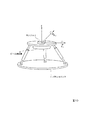
図2Aは図1におけるパラレルリンク20の構成概要を示したものであり、図中、21は固定ベースを示し、22はリンク機構を示す。また、23は可動テーブルを示し、可動テーブル23は伸縮可能な(直動機構を備えた)6本のリンク機構22により連結支持されて並進方向3自由度(X,Y,Z)、回転方向3自由度(θX,θY,θZ)の計6自由度で駆動されるものとなっている。
2A shows an outline of the configuration of the
可動テーブル23はこの例ではリング状をなす枠体23aと、その枠体23a内に位置する円板状の載置台23bとよりなり、載置台23bには一対の軸23cが突設されている。載置台23bはその一対の軸23cが枠体23aに軸支されることにより、回転(上下反転)可能とされている。6本のリンク機構22は枠体23aに連結されている。なお、軸23cを回転させ、載置台23bを上下反転させる機構(例えば、モータ等)の図示は省略している。
In this example, the movable table 23 includes a ring-shaped
可動テーブル23の載置台23bの上面には図2Bに示したように、加工対象物30が設置される。一方、載置台23bの下面側にはこの例ではイオン電流検出器50が取り付けられている。イオン電流検出器50は例えばファラデーカップとされる。
As shown in FIG. 2B, the
ガスクラスターイオンビームは輸送距離が長くなると、残留ガス分子との衝突によりクラスターが分解し、平坦化効果やエッチング効果の低下が起こる。そのため、ガスクラスターイオンビームの発生源から加工対象物30までの距離はできるだけ短かくするのが望ましい。この例ではイオン化室14の出口から150mmビームの中心が進行した地点Aでビームサイズが直径20mmになるようにアパーチャー18を用いて調整した。この距離150mmの近辺で加工対象物30に対するガスクラスターイオンビームの照射位置・角度を制御できるように、パラレルリンク20の原点位置を地点Aに一致させてパラレルリンク20を配置した。
When the transport distance of the gas cluster ion beam is increased, the cluster is decomposed by collision with residual gas molecules, and the planarization effect and the etching effect are reduced. Therefore, it is desirable to make the distance from the gas cluster ion beam source to the
図3は以下に示す実施例1で使用した加工対象物30の形状及び加工対象物30の座標定義について示したものである。円板状の載置台23bの上面の中心を原点とし、照射対象となる加工対象物30の各位置は原点からの(X,Y,Z)座標で表現する。なお、図3Bでは加工対象物30の底面の中心点が原点と一致するように加工対象物30を設置している。
FIG. 3 shows the shape of the
ガスクラスターイオンビームと加工対象物30との相対位置・角度の制御、即ちパラレルリンク20の駆動制御はパラレルリンク20の駆動制御部(図示せず)に加工対象物30の形状データ及び載置台23bへの加工対象物30の配置データを入力し、さらに以下の情報を入力することにより、所要の駆動を実現することができる。この情報とは、照射面(照射対象面)、照射の中心位置及び照射面に対する照射方向であり、照射面は加工対象物30の3個の座標もしくは照射面の法線ベクトルで表され、照射中心位置は1個の座標で表される。また、照射方向は1個の3次元ベクトル座標で表される。
The control of the relative position and angle between the gas cluster ion beam and the
原料ガスとしてArを用い、Arクラスターイオンビームを生成し、Arクラスターイオンを20kVに加速して加工対象物30に照射した。加工対象物30は図3Aに示した形状とし、図3Bに示したようにパラレルリンク20の可動テーブル23の載置台23b上に設置した。加工対象物30の構成材料はこの例ではSKD材(ダイス鋼)とした。
Ar was used as a source gas, an Ar cluster ion beam was generated, the Ar cluster ions were accelerated to 20 kV, and the
加工対象物30は直方体を2段重ねた形状であり、これら直方体の表面のうち、図3A及び下記に示すように6つの表面を表面a〜fと定義した。
表面a:上の直方体の左側面
表面b:下の直方体の左側面
表面c:上の直方体の右側面
表面d:上の直方体の背面
表面e:上の直方体の上面
表面f:下の直方体の上面
各面への加工に先立ち、まず、地点Aにおけるクラスターイオンビームの電流値を計測した。パラレルリンク20の可動テーブル23の載置台23bの下面に取り付けられているイオン電流検出器50を180°反転させ、検出面の中心位置が地点Aにくるようステージで位置調整を行った。クラスターイオンビームを発生させ、ビーム電流値を計測したところ、50μAであった。測定後、クラスターイオンビームの発生を一旦停止した。
The
Surface a: Left side of upper rectangular parallelepiped Surface b: Left side of lower rectangular parallelepiped Surface c: Right side of upper rectangular parallelepiped Surface d: Rear side of upper rectangular parallelepiped Surface e: Upper surface of upper rectangular parallelepiped Surface f: Lower rectangular parallelepiped Prior to processing on each surface, first, the current value of the cluster ion beam at point A was measured. The ion
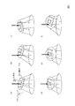
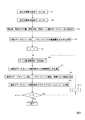
続いて、加工対象物30の表面aの一部をガスクラスターイオンビームを照射角度82度で照射して平坦化するため、パラレルリンク20の可動テーブル23を図5(a)に示すように移動させた。パラレルリンク20をこのように駆動制御するためにパラレルリンク20の駆動制御部に入力される情報、即ち照射面の法線ベクトル、照射中心位置(座標)、照射方向(3次元ベクトル座標)を図4に示した表1の(a)に示す。
Subsequently, the movable table 23 of the
表1(a)の情報を入力することによりパラレルリンク20の駆動制御部は所要の移動量を計算し、その計算値に従い、図5(a)に示したように可動テーブル23を移動させる。この状態でガスクラスターイオンビームを再び発生させた。照射実効ドーズ量が7×10¹⁶ions/cm2となる時間だけ照射を行い、その後クラスターイオンビームの発生を停止した。
By inputting the information in Table 1 (a), the drive control unit of the
次に、再び各面への加工に先立ち、まず、地点Aにおけるクラスターイオンビームの電流置を計測した。パラレルリンク20の可動テーブル23の載置台23bの下面に取り付けられているイオン電流検出器50を180°反転させ、検出面の中心位置が地点Aにくるようにステージで位置調整を行った。クラスターイオンビームを発生させ、ビーム電流値を測定したところ、49μAであった。測定後、クラスターイオンビームの発生を一旦停止した。
Next, prior to processing on each surface again, first, the current position of the cluster ion beam at the point A was measured. The ion
続いて、表面bの一部を平坦化するため、表1(b)の情報を入力し、パラレルリンク20の可動テーブル23を図5(b)に示すように移動させ、照射実効ドーズ量を同じく7×10¹⁶ions/cm2としてガスクラスターイオンビームを照射した。以下、同様に地点Aでのビーム電流値を計測後、表1(c)〜(f)の情報を与えることによりパラレルリンク20の可動テーブル23を図5(c)〜(f)に示すように順次移動させ、ガスクラスターイオンビームを順次、同じドーズ量だけ表面c〜fの一部に照射した。
Subsequently, in order to flatten a part of the surface b, the information of Table 1 (b) is input, the movable table 23 of the
照射前後の加工対象物30の表面粗さを原子間力顕微鏡(AFM)を用いて測定した。ビーム照射前の表面粗さRaはいずれも約0.20μmであったが、照射後の表面粗さRaはいずれも約0.14μmとなった。
The surface roughness of the
このように、この例では加工対象物30を6自由度のパラレルリンク20上に設置したことにより、加工対象物30の一つの平面上にない複数の表面a〜fを一つのプロセスで順次、平坦化することができ、かつその際、所望の照射角度(この例では82度)を選択して平坦化することができる。照射角度は加工面の法線とガスクラスターイオンビームがなす角度であって、この例では82度としているが、60度以上とすることで極めて優れた表面平坦化効果を得ることができる。
Thus, in this example, by setting the
なお、この例ではイオン電流検出器50がパラレルリンク20の可動テーブル23の載置台23bの下面に取り付けられているため、このイオン電流検出器50によってプロセス中に照射位置でのビーム電流値をモニタすることができ、これにより必要な照射量だけ照射することができる。
In this example, since the ion
即ち、ガスクラスターイオンビームを加工面に照射する前に、載置台23bを上下反転させてイオン電流検出器50でビーム電流値をモニタすることにより、ビーム電流値から照射ドーズ量に対応する照射時間を求めることができ、載置台23bを反転させて、その求めた照射時間だけ照射することで、加工面に必要な照射量の照射を行うことができる。これにより、加工対象物30の複数の加工面、さらには複数の加工対象物30を均一に加工することができる。ビーム電流値のモニタはプロセス時間が短く、ビーム電流値をモニタした場所に常に加工面を位置させることができる場合には、プロセス開始前に一度行うだけでもよい。
That is, before irradiating the processing surface with the gas cluster ion beam, the mounting table 23b is turned upside down and the beam current value is monitored by the ion
なお、この例では平坦化加工の例を示したが、各面を所望の量だけエッチングする用途についても同様の手順で行うことができる。 In addition, although the example of the planarization process was shown in this example, it can carry out in the same procedure also about the use which etches each surface by desired amount.
パラレルリンク20を図6に示したようにステージ60上に搭載した。ステージ60は図6では簡略化して示しているが、X,Y,Z3軸のリニアステージとした。この例では並進方向の3自由度(X,Y,Z)をステージ60によって担うものとし、回転方向の3自由度(θX,θY,θZ)をパラレルリンク20が担うものとした。
The
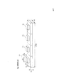
図7に示した加工対象物30’をパラレルリンク20の載置台23b上に設置した。この加工対象物30’は実施例1における加工対象物30が4個連結された形状となっている。
The
この加工対象物30’の(1)〜(4)の各部分にある表面a〜f(図3A参照)をステージ60及びパラレルリンク20を駆動制御し、実施例1と同様にガスクラスターイオンビームを順次、照射して平坦化した。
The surface a to f (see FIG. 3A) on each part (1) to (4) of the
照射前後の加工対象物30’の表面粗さを原子間力顕微鏡(AFM)を用いて測定した。ビーム照射前の表面粗さRaは(1)〜(4)の各部分の各表面a〜fでいずれも約0.23μmであったが、照射後の表面粗さRaはいずれも約0.15μmとなった。
The surface roughness of the
このように加工対象物30’の形状や大きさによってはパラレルリンク20とステージ60とを組み合わせて使用することにより、一つのプロセスで複数の加工面を良好に加工することができる。なお、ステージ60はX,Y,Z3軸のリニアステージに限らず、用途に応じて例えばX,Y2軸のリニアステージとすることもできる。
As described above, depending on the shape and size of the
実施例2においてもイオン電流検出器50によりプロセス中に適宜、ビーム電流値をモニタし、ビーム電流値から照射ドーズ量に対応する照射時間を求めて照射するようにすれば、必要な照射量だけ照射を行うことができ、加工対象物30’の各加工面を均一に加工することができる。
Also in the second embodiment, if the ion
なお、この例では平坦化加工の例を示したが、各面を所望の量だけエッチングする用途についても同様の手順で行うことができる。 In addition, although the example of the planarization process was shown in this example, it can carry out in the same procedure also about the use which etches each surface by desired amount.
上述した実施例ではパラレルリンク20の可動テーブル23を枠体23aと上下反転可能な載置台23bとよりなるものとして、載置台23bの下面側にイオン電流検出器50を設置し、載置台23bを適宜、反転させることによってビーム電流値をモニタ可能としているが、これに替え、例えば図8に示したような構成を採用することもできる。
In the embodiment described above, the movable table 23 of the
図8ではパラレルリンク20’の可動テーブル23’の下面にイオン電流検出器50を取り付け、このイオン電流検出器50に入射するガスクラスターイオンビームが通過する貫通孔23dを可動テーブル23’に設けたものとなっており、このような構成を採用すれば可動テーブル23’を反転させることなく、ビーム電流値をモニタすることができる。貫通孔23dはわずかな大きさがあればよく、例えば直径1mm程度以上の大きさがあればよい。この貫通孔23dをパラレルリンク20’あるいはリニアステージを移動することによってスキャンする方法により、ビーム電流値およびビーム電流分布を知ることができる。なお、図8Bでは可動テーブル23’上に貫通孔23dの位置を避け、2つの加工対象物30が設置された状態を示している。
In FIG. 8, an ion
加工対象物30(30’)は上述した実施例ではパラレルリンク20(20’)の可動テーブル23(23’)上に直接、設置するものとしているが、例えばパラレルリンクとは別に加工対象物を設置・支持する支持台を用意し、この支持台を介して加工対象物をパラレルリンク上に設置するようにしてもよい。
In the above-described embodiment, the workpiece 30 (30 ′) is directly installed on the movable table 23 (23 ′) of the parallel link 20 (20 ′). For example, the
図9は前述した実施例1における加工対象物30の複数の表面を順次平坦化する加工を自動的に行う場合の手順をフローチャートで示したものであり、図1に示した加工装置に全体を制御する制御手段を設け、その制御手段の制御ソフトウエアのプログラムを用いることにより、複数の表面を自動的に加工することができる。以下、手順を説明する。
FIG. 9 is a flowchart showing a procedure in the case of automatically performing the process of sequentially flattening a plurality of surfaces of the
まず、プログラムに加工対象物の形状データと、パラレルリンクに対する加工対象物の配置データを入力する(ステップS1,S2)。次に、ガスクラスターイオンビームを照射する面、照射の中心位置、照射方向及び照射ドーズ量のデータセットを平坦化が必要な照射条件(照射面)の数だけ(N個)指定する(ステップS3)。この指定された各条件により加工対象物にガスクラスターイオンビームを照射するために必要なパラレルリンクの駆動量がそれぞれ計算される(ステップS4)。 First, the shape data of the workpiece and the arrangement data of the workpiece relative to the parallel link are input to the program (steps S1 and S2). Next, a data set of the irradiation surface, irradiation center position, irradiation direction, and irradiation dose amount for the gas cluster ion beam is designated by the number of irradiation conditions (irradiation surfaces) that need to be flattened (N) (step S3). ). The drive amount of the parallel link necessary for irradiating the object to be processed with the gas cluster ion beam is calculated according to each specified condition (step S4).
n=1とし(ステップS5)、ビーム電流値In(n=1)をパラレルリンク可動テーブル下面の電流検出器で測定する(ステップS6)。次に、n=1番目のデータセットの照射条件での照射時間tn(n=1)を、測定したビーム電流値In(n=1)から計算する(ステップS7)。n=1番目のデータセットに対応してパラレルリンクを駆動し、tn(n=1)の時間だけ姿勢を保持させる(ステップS8)。直ちにガスクラスターイオンビームをONにし、指定のドーズ量に相当する時間、即ちt1だけビームの照射が行われる(ステップS9)。続いて、n=n+1とされ(ステップS11)、n=2番目のデータセットに対応してパラレルリンクが駆動され、ビーム電流値を測定し、指定のドーズ量に相当する時間、t2だけビームの照射が行われる。 n = 1 is set (step S5), and the beam current value In (n = 1) is measured by the current detector on the lower surface of the parallel link movable table (step S6). Next, the irradiation time tn (n = 1) under the irradiation condition of the n = 1st data set is calculated from the measured beam current value In (n = 1) (step S7). The parallel link is driven corresponding to the n = 1st data set, and the posture is held for the time of tn (n = 1) (step S8). Immediately after the gas cluster ion beam is turned on, the beam is irradiated for a time corresponding to the designated dose, ie, t 1 (step S9). Then, set to n = n + 1 (step S11), the parallel link corresponding to n = 2 th data set is driven, the time to measure the beam current value, corresponding to a dose of specified, only t 2 beams Irradiation is performed.
以下、同様に3番目、4番目、…のデータセットに対応してパラレルリンクが順次、駆動され、指定のドーズ量に相当する時間だけ、順次ビームの照射が行われる。最後に入力されたデータセット(n=N)の条件での照射を終えると(ステップS10)、ガスクラスターイオンビームをOFFにし、ビームの照射を終了する。 Similarly, the parallel links are sequentially driven corresponding to the third, fourth,... Data sets, and beam irradiation is sequentially performed for a time corresponding to the designated dose amount. When the irradiation under the condition of the last input data set (n = N) is completed (step S10), the gas cluster ion beam is turned off and the beam irradiation is ended.
上記におけるビームのON/OFFは例えばビームと加工対象物との間に設置したシャッタのON/OFFあるいはガスクラスターイオンビームの加速電圧を20kV(ON)と0kV(OFF)にする制御により行うことができる。 The ON / OFF of the beam in the above is performed, for example, by controlling ON / OFF of a shutter installed between the beam and the workpiece or controlling the acceleration voltage of the gas cluster ion beam to 20 kV (ON) and 0 kV (OFF). it can.
また、ビーム電流値の測定はn=1の場合のみ行い、n>1の場合のビーム電流値InはI1と同じとしてプロセス時間を短縮するフローも実施可能である。 Further, the measurement of the beam current value is performed only when n = 1, and the beam current value In when n> 1 is the same as I 1, and a flow for shortening the process time can be performed.
Claims (5)
パラレルリンク構造のステージを具備し、
そのパラレルリンクで囲まれた空間にビーム検出器を有することを特徴とする固体表面の加工装置。 An apparatus for processing a solid surface using a gas cluster ion beam,
It has a stage with a parallel link structure,
A solid surface processing apparatus comprising a beam detector in a space surrounded by the parallel links.
前記パラレルリンクは前記ガスクラスターイオンビームに対する加工対象物の位置・角度を並進方向3自由度、回転方向3自由度の計6自由度で制御可能とされ、
前記パラレルリンクの可動テーブルの、前記加工対象物が搭載される上面側と反対の下面に前記ビーム検出器が設置され、
前記可動テーブルが上下反転可能とされていることを特徴とする固体表面の加工装置。 In the processing apparatus of the solid surface of Claim 1,
The parallel link can control the position / angle of the workpiece with respect to the gas cluster ion beam with a total of 6 degrees of freedom, 3 degrees of freedom in the translation direction and 3 degrees of freedom in the rotation direction,
The beam detector is installed on the lower surface of the movable table of the parallel link opposite to the upper surface side on which the workpiece is mounted,
An apparatus for processing a solid surface, wherein the movable table can be turned upside down.
前記パラレルリンクは前記ガスクラスターイオンビームに対する加工対象物の位置・角度を並進方向3自由度、回転方向3自由度の計6自由度で制御可能とされ、
前記パラレルリンクの可動テーブルの、前記加工対象物が搭載される上面側と反対の下面に前記ビーム検出器が設置され、
前記ビーム検出器に入射するガスクラスターイオンビームが通過する貫通孔が前記可動テーブルに設けられていることを特徴とする固体表面の加工装置。 In the processing apparatus of the solid surface of Claim 1,
The parallel link can control the position / angle of the workpiece with respect to the gas cluster ion beam with a total of 6 degrees of freedom, 3 degrees of freedom in the translation direction and 3 degrees of freedom in the rotation direction,
The beam detector is installed on the lower surface of the movable table of the parallel link opposite to the upper surface side on which the workpiece is mounted,
An apparatus for processing a solid surface, wherein a through-hole through which a gas cluster ion beam incident on the beam detector passes is provided in the movable table.
前記パラレルリンクが2軸もしくは3軸のリニアステージ上に設置されていることを特徴とする固体表面の加工装置。 In the processing apparatus of the solid surface in any one of Claims 1 thru | or 3,
A solid surface processing apparatus, wherein the parallel link is installed on a two-axis or three-axis linear stage.
前記パラレルリンクが予め複数個設定された前記加工対象物への前記ガスクラスターイオンビームの照射位置・照射角度・照射量に基づき、順次駆動制御されることを特徴とする固体表面の加工装置。 In the processing apparatus of the solid surface in any one of Claims 1 thru | or 4,
An apparatus for processing a solid surface, which is sequentially driven and controlled on the basis of an irradiation position, an irradiation angle, and an irradiation amount of the gas cluster ion beam to the object to be processed in which a plurality of the parallel links are set in advance.
Priority Applications (1)
| Application Number | Priority Date | Filing Date | Title |
|---|---|---|---|
| JP2008163126A JP5026354B2 (en) | 2008-06-23 | 2008-06-23 | Solid surface processing equipment |
Applications Claiming Priority (1)
| Application Number | Priority Date | Filing Date | Title |
|---|---|---|---|
| JP2008163126A JP5026354B2 (en) | 2008-06-23 | 2008-06-23 | Solid surface processing equipment |
Publications (2)
| Publication Number | Publication Date |
|---|---|
| JP2010003955A true JP2010003955A (en) | 2010-01-07 |
| JP5026354B2 JP5026354B2 (en) | 2012-09-12 |
Family
ID=41585411
Family Applications (1)
| Application Number | Title | Priority Date | Filing Date |
|---|---|---|---|
| JP2008163126A Active JP5026354B2 (en) | 2008-06-23 | 2008-06-23 | Solid surface processing equipment |
Country Status (1)
| Country | Link |
|---|---|
| JP (1) | JP5026354B2 (en) |
Citations (4)
| Publication number | Priority date | Publication date | Assignee | Title |
|---|---|---|---|---|
| JPH10333749A (en) * | 1997-05-30 | 1998-12-18 | Mitsubishi Electric Corp | Driving controller for plural degree-of-freedom parallel link mechanism |
| JP2004276181A (en) * | 2003-03-17 | 2004-10-07 | Olympus Corp | Parallel link stage device |
| JP2006244720A (en) * | 2005-02-28 | 2006-09-14 | Jeol Ltd | Beam apparatus |
| JP2008502150A (en) * | 2004-06-03 | 2008-01-24 | エピオン コーポレーション | Improved dual damascene integrated structure and method of manufacturing the same |
-
2008
- 2008-06-23 JP JP2008163126A patent/JP5026354B2/en active Active
Patent Citations (4)
| Publication number | Priority date | Publication date | Assignee | Title |
|---|---|---|---|---|
| JPH10333749A (en) * | 1997-05-30 | 1998-12-18 | Mitsubishi Electric Corp | Driving controller for plural degree-of-freedom parallel link mechanism |
| JP2004276181A (en) * | 2003-03-17 | 2004-10-07 | Olympus Corp | Parallel link stage device |
| JP2008502150A (en) * | 2004-06-03 | 2008-01-24 | エピオン コーポレーション | Improved dual damascene integrated structure and method of manufacturing the same |
| JP2006244720A (en) * | 2005-02-28 | 2006-09-14 | Jeol Ltd | Beam apparatus |
Also Published As
| Publication number | Publication date |
|---|---|
| JP5026354B2 (en) | 2012-09-12 |
Similar Documents
| Publication | Publication Date | Title |
|---|---|---|
| TWI389181B (en) | Improved ion beam utilization during scanned ion implantation | |
| US7442942B2 (en) | Charged particle beam apparatus | |
| US11462381B2 (en) | Composite charged particle beam apparatus | |
| US7700367B2 (en) | Method of making lamina specimen | |
| US9911573B2 (en) | Methods, apparatuses, systems and software for treatment of a specimen by ion-milling | |
| US7718981B2 (en) | Composite charged-particle beam system | |
| JP5254613B2 (en) | Directed multi-deflection ion beam milling of workpieces and determination and control of their extent | |
| TWI642079B (en) | Charged particle beam device and sample observation method | |
| JP2010508624A (en) | Mechanical scanner for ion implanters | |
| KR20050047103A (en) | A single-shot semiconductor processing system and method having various irradiation patterns | |
| CN106435595A (en) | System and method for de-engineering a sample to reverse engineer a sample | |
| JP5695818B2 (en) | Cross-section processing method and cross-section observation sample manufacturing method | |
| CN105957789B (en) | Method, apparatus, system and software for processing a sample by ion milling | |
| JP2011203266A (en) | Thin sample preparing method | |
| US7755044B2 (en) | Apparatus for working and observing samples and method of working and observing cross sections | |
| TWI654643B (en) | Ion implantation system and method for ion implantation | |
| JP5026354B2 (en) | Solid surface processing equipment | |
| JP2009037910A (en) | Composite charged particle beam device, and process observation method | |
| TWI455170B (en) | Method and apparatus for measurement of beam angle in ion implantation | |
| KR101522875B1 (en) | Specimen preparation apparatus | |
| CN110520241A (en) | Laser processing machine | |
| JPH08206866A (en) | Energy beam processing method and energy beam processing device | |
| JP7078632B2 (en) | Compensation position identification processing device and method | |
| US20080169435A1 (en) | Ion beam monitoring arrangement | |
| WO2022044068A1 (en) | Plasma processor and trajectory correction method for plasma processor |
Legal Events
| Date | Code | Title | Description |
|---|---|---|---|
| A621 | Written request for application examination |
Free format text: JAPANESE INTERMEDIATE CODE: A621 Effective date: 20110520 |
|
| A131 | Notification of reasons for refusal |
Free format text: JAPANESE INTERMEDIATE CODE: A131 Effective date: 20120327 |
|
| A977 | Report on retrieval |
Free format text: JAPANESE INTERMEDIATE CODE: A971007 Effective date: 20120329 |
|
| A521 | Request for written amendment filed |
Free format text: JAPANESE INTERMEDIATE CODE: A523 Effective date: 20120524 |
|
| TRDD | Decision of grant or rejection written | ||
| A01 | Written decision to grant a patent or to grant a registration (utility model) |
Free format text: JAPANESE INTERMEDIATE CODE: A01 Effective date: 20120612 |
|
| A01 | Written decision to grant a patent or to grant a registration (utility model) |
Free format text: JAPANESE INTERMEDIATE CODE: A01 |
|
| A61 | First payment of annual fees (during grant procedure) |
Free format text: JAPANESE INTERMEDIATE CODE: A61 Effective date: 20120620 |
|
| FPAY | Renewal fee payment (event date is renewal date of database) |
Free format text: PAYMENT UNTIL: 20150629 Year of fee payment: 3 |
|
| R150 | Certificate of patent or registration of utility model |
Ref document number: 5026354 Country of ref document: JP Free format text: JAPANESE INTERMEDIATE CODE: R150 Free format text: JAPANESE INTERMEDIATE CODE: R150 |
|
| R250 | Receipt of annual fees |
Free format text: JAPANESE INTERMEDIATE CODE: R250 |
|
| R250 | Receipt of annual fees |
Free format text: JAPANESE INTERMEDIATE CODE: R250 |
|
| R250 | Receipt of annual fees |
Free format text: JAPANESE INTERMEDIATE CODE: R250 |
|
| R250 | Receipt of annual fees |
Free format text: JAPANESE INTERMEDIATE CODE: R250 |
|
| R250 | Receipt of annual fees |
Free format text: JAPANESE INTERMEDIATE CODE: R250 |
|
| R250 | Receipt of annual fees |
Free format text: JAPANESE INTERMEDIATE CODE: R250 |
|
| R250 | Receipt of annual fees |
Free format text: JAPANESE INTERMEDIATE CODE: R250 |
|
| R250 | Receipt of annual fees |
Free format text: JAPANESE INTERMEDIATE CODE: R250 |
|
| R250 | Receipt of annual fees |
Free format text: JAPANESE INTERMEDIATE CODE: R250 |