JP2010002133A - Gas supply device - Google Patents
Gas supply device Download PDFInfo
- Publication number
- JP2010002133A JP2010002133A JP2008161722A JP2008161722A JP2010002133A JP 2010002133 A JP2010002133 A JP 2010002133A JP 2008161722 A JP2008161722 A JP 2008161722A JP 2008161722 A JP2008161722 A JP 2008161722A JP 2010002133 A JP2010002133 A JP 2010002133A
- Authority
- JP
- Japan
- Prior art keywords
- gas
- pressure
- air
- valve
- raw material
- Prior art date
- Legal status (The legal status is an assumption and is not a legal conclusion. Google has not performed a legal analysis and makes no representation as to the accuracy of the status listed.)
- Granted
Links
Images

Landscapes
- Feeding, Discharge, Calcimining, Fusing, And Gas-Generation Devices (AREA)
- Feeding And Controlling Fuel (AREA)
- Accessories For Mixers (AREA)
Abstract
Description
この発明は、液化石油ガス等の原料ガスと空気とを混合して、都市ガス(13A等)と同等の燃焼性を有する混合ガスを供給するガス供給装置に関する。 The present invention relates to a gas supply apparatus that mixes a raw material gas such as liquefied petroleum gas and air to supply a mixed gas having combustibility equivalent to that of city gas (13A or the like).
移動式のガス供給装置は、液化石油ガス等の原料ガスに空気を混合して、都市ガスと同等の発熱量を有する混合ガスを調製して一時的に貯蔵する装置一式を、トラックの荷台等に載置して移動可能にしたものである。例えば、自然災害が発生して都市ガスの供給が停止した際に、その供給エリアにこの移動式ガス供給装置を移動させ、その供給エリアにて供給されていた都市ガス(13A、12A等)と同等の発熱量を有する混合ガスを、都市ガスの代用として供給する。これによって、都市ガスが復旧するまでの間、ガスの供給を賄うことができる。 Mobile gas supply equipment is a set of equipment that mixes air with raw gas such as liquefied petroleum gas to prepare a mixed gas having a calorific value equivalent to that of city gas and temporarily stores it, such as a truck bed It can be placed and moved. For example, when a natural disaster occurs and the supply of city gas stops, the mobile gas supply device is moved to the supply area, and the city gas (13A, 12A, etc.) supplied in the supply area A mixed gas having the same calorific value is supplied as a substitute for city gas. Thereby, gas supply can be covered until city gas is restored.
このガス供給装置として、原料ガスをベンチュリーミキサーで混合してサージタンクに貯蔵する混合装置一式をキャスターの付いたキャビネット上に載置したものが開示されている(特許文献1参照)。このベンチュリーミキサーは、ノズルから原料ガスを噴射するとともに、この噴射に伴って発生する負圧によってノズル周囲の空気を巻きこみつつ混合して、所定混合比率の混合ガスを調製する公知のものである。
一般的なガス機器(例えば、ガスコンロ)においては、必要とされる機器ガス圧は1.5〜2.5kPa程度の低圧なので、供給エリアが狭い場合(供給家庭数が数戸分程度)は、それを若干上回る程度の供給圧力があれば、各家庭において支障なくガス機器を使用することができる。その一方で、供給エリアが広い場合(供給家庭数が数十戸分以上)や、導管工事等の際は、各家庭に到達した際における前記ガス圧を確保するために、サージタンクのガス圧をかなり高圧(例えば、300kPa程度)にしておく必要が生じることもある。 In general gas equipment (for example, gas stove), the required equipment gas pressure is a low pressure of about 1.5 to 2.5 kPa, so when the supply area is narrow (the number of supply households is about several units), If there is a supply pressure slightly higher than that, gas appliances can be used without problems in each household. On the other hand, when the supply area is large (the number of supply households is more than several tens of households), or when pipe work is performed, the gas pressure in the surge tank is secured to ensure the gas pressure when reaching each household. May need to be kept at a fairly high pressure (for example, about 300 kPa).
このサージタンクのガス圧を高めるには、前記ノズルからの原料ガスの噴射圧力を高めて、より多くの原料ガスをサージタンクに送り込むようにする。それとともに、送り込んだ原料ガスの量に見合う大量の空気を送り込んで、このサージタンク内の混合ガスが所定の混合比率(通常は、原料ガス:空気=6:4程度)を維持するようにする。前記噴射圧力は、原料ガスボンベの圧力を減圧する中圧調整器の調節ネジを調節して、バネによるダイヤフラムの付勢力を大きくして、この中圧調整器に設けた弁体の開弁度を高めることによって、より大きくすることができる。 In order to increase the gas pressure in the surge tank, the injection pressure of the raw material gas from the nozzle is increased so that more raw material gas is fed into the surge tank. At the same time, a large amount of air corresponding to the amount of the raw material gas sent in is sent so that the mixed gas in the surge tank maintains a predetermined mixing ratio (usually, raw material gas: air = about 6: 4). . The injection pressure is adjusted by adjusting an adjustment screw of an intermediate pressure regulator for reducing the pressure of the raw material gas cylinder to increase the urging force of the diaphragm by a spring, and the opening degree of the valve body provided in the intermediate pressure regulator is increased. By raising it, it can be made larger.
背景技術に係る中圧調整器の調節ネジは、そのねじ込み量に限度があるため、その噴射圧力は、高々数倍程度の範囲内でしか調節できない。このため、上述したように、低圧から高圧まで、幅広く調節する必要のある用途には適さないという問題がある。
また、仮に、前記バネに弾性力の高いものを採用して原料ガスの噴射圧力を高めたとしても、大気圧下においては、その原料ガスの量に見合った、十分な量の空気を前記ベンチュリーミキサーの空気取り込み口から取り込むことができない。このため、混合ガスの混合比率が、所定の範囲から外れるという問題もある。
Since the adjusting screw of the intermediate pressure regulator according to the background art has a limited screwing amount, the injection pressure can be adjusted only within a range of several times at most. For this reason, as described above, there is a problem that it is not suitable for applications that need to be widely adjusted from low pressure to high pressure.
Further, even if the spring has a high elastic force and the injection pressure of the source gas is increased, a sufficient amount of air corresponding to the amount of the source gas is supplied under the atmospheric pressure. It cannot be taken in from the air intake port of the mixer. For this reason, there is also a problem that the mixing ratio of the mixed gas is out of the predetermined range.
そこで、この発明は、必要とされる供給圧力に対応して、その供給圧力を幅広い範囲で調節自在とするとともに、その調節の際に、原料ガスと空気との混合比率を所定の範囲内に維持し得るようにすることを課題とする。 Therefore, according to the present invention, the supply pressure can be adjusted in a wide range corresponding to the required supply pressure, and the mixing ratio of the raw material gas and air is set within a predetermined range at the time of the adjustment. The problem is to be able to maintain it.
前記の課題を解決するため、この発明は、中圧調整器に加圧空気を導入して、この中圧調整器に設けたダイヤフラムの付勢力を調節することによって、原料ガスの噴射圧力(中圧調整器の出口圧力)を低圧から高圧まで自在に調節し得るようにするとともに、前記加圧空気をベンチュリーミキサーにも導入して、このベンチュリーミキサーで前記原料ガスと空気とを混合した際に、その混合比率を所定の範囲内に維持し得るようにした。 In order to solve the above-mentioned problems, the present invention introduces pressurized air into the intermediate pressure regulator and adjusts the urging force of the diaphragm provided in the intermediate pressure regulator, so that the injection pressure of the source gas (medium The pressure regulator outlet pressure) can be freely adjusted from low pressure to high pressure, and the pressurized air is also introduced into the venturi mixer, and when the raw gas and air are mixed with the venturi mixer The mixing ratio can be maintained within a predetermined range.
前記噴射圧力の最大値は、前記中圧調整器内部のダイヤフラムに設けたバネの付勢力と、加圧空気の付勢力の合計によって決まり、前記加圧空気の圧力を高めることによって、その最大値を自在に高めることができる。しかも、前記加圧空気による加圧を解除すれば、前記バネの付勢力のみに基づいた前記噴射圧力の調節がなされるので、幅広い噴射圧力範囲内での調節が可能となる。
また、前記加圧空気をベンチュリーミキサーにも導入することによって、前記噴射圧力によって噴射される原料ガスの量に見合った量の空気を供給できる。このため、混合ガスの混合比率を所定の範囲内に維持し得る。
The maximum value of the injection pressure is determined by the sum of the urging force of the spring provided in the diaphragm inside the intermediate pressure regulator and the urging force of the pressurized air, and the maximum value is obtained by increasing the pressure of the pressurized air. Can be increased freely. In addition, if the pressurization by the pressurized air is released, the injection pressure is adjusted based only on the urging force of the spring, so that adjustment within a wide injection pressure range is possible.
In addition, by introducing the pressurized air into the venturi mixer, it is possible to supply an amount of air commensurate with the amount of source gas injected by the injection pressure. For this reason, the mixing ratio of the mixed gas can be maintained within a predetermined range.
この発明の構成として、原料ガスボンベの原料ガスをベンチュリーミキサーで空気と混合してクッションタンクに貯蔵し、この貯蔵した混合ガスを家庭等の需要者に供給するようにしたガス供給装置において、本装置にコンプレッサを併設し、このコンプレッサから吐出された加圧空気を、前記原料ガスボンベのガス圧を減圧して前記ベンチュリーミキサーに送出する中圧調整器のダイヤフラムのバネ室に送り込んで、このダイヤフラムに設けた弁体を開弁方向に付勢して、前記中圧調整器から前記ベンチュリーミキサーへの原料ガスの送出圧を高めるとともに、前記加圧空気を、前記原料ガスと混合する空気の吸入量を調節する空気弁のダイヤフラムのバネ室、及び、前記空気弁の空気取り込み口の双方にも送り込んで前記空気弁の空気吸入圧を高め、前記ベンチュリーミキサーで前記原料ガスと空気とを混合してクッションタンクに貯蔵した際に、混合ガスのガス圧を高め得るようにしつつ、その混合比率を予め決めた所定範囲内に維持し得るようにすることができる。 In the gas supply apparatus according to the present invention, the raw material gas of the raw material gas cylinder is mixed with air by a venturi mixer and stored in a cushion tank, and the stored mixed gas is supplied to consumers such as households. A compressor is also provided, and the compressed air discharged from the compressor is sent to the diaphragm spring chamber of the intermediate pressure regulator that reduces the gas pressure of the source gas cylinder and sends it to the venturi mixer. The valve body is urged in the valve opening direction to increase the feed pressure of the raw material gas from the intermediate pressure regulator to the venturi mixer, and the amount of air sucked into the pressurized gas to be mixed with the raw material gas is increased. It is sent to both the spring chamber of the diaphragm of the air valve to be adjusted and the air intake port of the air valve, and the air suction of the air valve When the pressure is increased and the source gas and air are mixed and stored in the cushion tank by the Venturi mixer, the gas pressure of the mixed gas can be increased while maintaining the mixing ratio within a predetermined range. It can be done.
前記中圧調整器のバネ室に送り込んだ加圧空気の圧力は、前記コンプレッサの稼動・停止によって、適宜昇降させることができる。これによって、必要とされる混合ガスの供給圧力に対応して、クッションタンク内の混合ガス圧を広い範囲内(例えば、数kPa〜数100kPa)で調節することができ、一台の装置で幅広い用途に対応し得る。
また、原料ガスを高いガス圧のまま供給するとともに、空気を加圧した状態で供給することにより、従来のガス供給装置と比較して、混合ガスの製造能力を大幅に向上し得る。
The pressure of the pressurized air sent into the spring chamber of the intermediate pressure regulator can be raised or lowered as appropriate by operating or stopping the compressor. As a result, the mixed gas pressure in the cushion tank can be adjusted within a wide range (for example, several kPa to several hundred kPa) corresponding to the required mixed gas supply pressure. It can correspond to the application.
Further, by supplying the raw material gas at a high gas pressure and supplying the air in a pressurized state, the production capacity of the mixed gas can be greatly improved as compared with the conventional gas supply device.
前記ダイヤフラムは、上述したように通常はバネで付勢されているが、このバネを用いずに前記加圧空気のみで付勢するようにしてもよい。この場合も、加圧空気の圧力を調節することで、必要に応じて、前記クッションタンク内の混合ガス圧を幅広い範囲内で調節し得るからである。 The diaphragm is normally biased by a spring as described above, but may be biased only by the pressurized air without using this spring. Also in this case, by adjusting the pressure of the pressurized air, the mixed gas pressure in the cushion tank can be adjusted within a wide range as necessary.
前記ベンチュリーミキサーは、一般的に市販されているものと同じであって、その内部にノズルと、そのノズルの近傍に空気取り入れ口とが設けられている。上述したように、このノズルから噴射した原料ガスの噴射量に対応した量の空気を前記空気取り入れ口から取り込んで、両者をほぼ一定の比率で混合する機能を有している。この構成においては、前記空気取り入れ口に設けた空気弁にも加圧空気が送り込まれるので、原料ガスの噴射量に対応した十分な量の空気を混合し得る。このため、混合空気量が不足して、前記混合ガスの混合比率が所定範囲(例えば、都市ガス(13A)の代用であれば、原料ガス:空気=6:4程度)から外れる恐れが低い。 The Venturi mixer is generally the same as a commercially available one, and has a nozzle inside and an air intake near the nozzle. As described above, it has a function of taking in an amount of air corresponding to the injection amount of the raw material gas injected from the nozzle from the air intake port and mixing them at a substantially constant ratio. In this configuration, since the pressurized air is also sent to the air valve provided at the air intake port, a sufficient amount of air corresponding to the injection amount of the raw material gas can be mixed. For this reason, there is a low possibility that the amount of mixed air will be insufficient and the mixing ratio of the mixed gas will be out of a predetermined range (for example, source gas: air = about 6: 4 if it is a substitute for city gas (13A)).
前記コンプレッサの動力源として、例えば、ディーゼルエンジンを採用することができる。このガス供給装置は、ガス供給が必要とされる現地に持ち込んで使用するものなので、その現地で必ずしも電力供給源を使用し得るとは限らない。また、大規模な自然災害時には、ガス供給とともに電力供給も停止することも多い。このような場合でも、他からの電力供給を必要としないディーゼルエンジンを用いることによって、必要に応じてすぐに本装置を使用することができる。前記動力源は、もちろんこれに限定されるものではなく、電気式のものとしたり、電気式とディーゼル式を併用するものとしたりすることもできる。 For example, a diesel engine can be employed as a power source for the compressor. Since this gas supply apparatus is used by bringing it to a site where gas supply is required, the power supply source cannot always be used at that site. In addition, during a large-scale natural disaster, power supply is often stopped together with gas supply. Even in such a case, by using a diesel engine that does not require any other power supply, the present apparatus can be used immediately as needed. Of course, the power source is not limited to this, and may be an electric type or a combination of an electric type and a diesel type.
この構成においては、前記コンプレッサの吐出口側にガバナを設けるとともに、このガバナの出口側の空気配管を二股に分岐して、一方を前記各バネ室側に、他方を前記空気取り込み口側に接続し、前記ガバナで、加圧空気の加圧量を調節し得るようにすることができる。 In this configuration, a governor is provided on the discharge port side of the compressor, and an air pipe on the outlet side of the governor is bifurcated so that one is connected to each spring chamber side and the other is connected to the air intake port side. In addition, the amount of pressurized air can be adjusted with the governor.
上述のように、コンプレッサの稼動・停止のみによってもある程度はクッションタンク内の混合ガス圧を調節し得るが、このようにガバナを設けることによって、各バネ室の加圧量(原料ガスの噴射圧)が安定して維持される。このため、クッションタンク内の圧力変動が小さくなって、需要者への安定供給が可能となる。
また、前記ベンチュリーミキサーは原料ガスの噴射圧に対応した量の空気を取り込む構造なので、このクッションタンク内の混合ガスの混合比率が大きく変動する恐れは小さい。
As described above, the mixed gas pressure in the cushion tank can be adjusted to some extent only by operating / stopping the compressor. However, by providing the governor in this way, the amount of pressurization of each spring chamber (the injection pressure of the raw material gas) ) Is maintained stably. For this reason, the pressure fluctuation in a cushion tank becomes small, and the stable supply to a consumer is attained.
Further, since the venturi mixer has a structure that takes in an amount of air corresponding to the injection pressure of the raw material gas, there is little possibility that the mixing ratio of the mixed gas in the cushion tank will fluctuate greatly.
あるいは、前記ガバナの出口側の空気配管を二股に分岐する代わりに、前記コンプレッサの吐出口側の空気配管を二股に分岐するとともに、分岐した両空気配管にそれぞれガバナを設け、一方のガバナからの空気配管を前記各バネ室側に、他方のガバナからの空気配管を前記空気取り込み口側に接続し、前記一方のガバナで加圧空気の加圧量を調節し得るようにする一方で、前記他方のガバナで混合ガスの混合比率を調節するようにすることもできる。 Alternatively, instead of bifurcating the air pipe on the outlet side of the governor, the air pipe on the discharge port side of the compressor is bifurcated, and a governor is provided in each of the branched air pipes. While connecting the air piping to the respective spring chamber side, connecting the air piping from the other governor to the air intake port side, the pressurization amount of the pressurized air can be adjusted by the one governor, It is also possible to adjust the mixing ratio of the mixed gas with the other governor.
上述のように、1基のガバナでも、クッションタンク内の所望の混合ガス圧を確保しつつ、所定の混合比率をほぼ所定の範囲内に調節することもできるが、前記混合ガス圧の調節と、混合比率の調節とを別々のガバナに担わせることによって、前記混合比率の制御を一層正確に行い得る。 As described above, even with one governor, it is possible to adjust the predetermined mixing ratio within a predetermined range while ensuring a desired mixed gas pressure in the cushion tank. By controlling the mixing ratio to different governors, the mixing ratio can be controlled more accurately.
また、前記各構成において、前記加圧空気を、前記中圧調整器と前記ベンチュリーミキサーとの間に設けた開閉弁、前記開閉弁の開閉を制御する開閉弁コントローラ、前記遮断弁の開閉を制御する上下限圧遮断コントローラ、及び、前記クッションタンクの過昇圧を防止する昇圧防止弁のそれぞれに設けたダイヤフラムのバネ室にも送り込み、前記ベンチュリーミキサーへの原料ガスの送出圧が高い場合においても、前記各弁及び各コントローラが正常に動作し得るようにするとともに、前記上下限圧遮断コントローラ、前記昇圧防止弁、及び、前記ベンチュリーミキサーの空気取り込み口のそれぞれと、原料ガスボンベからの原料ガスの供給を遮断する遮断弁とを接続し、前記中圧調整器からの原料ガスの供給圧力、前記クッションタンク内の混合ガス圧、又は、前記ベンチュリーミキサーでの空気吸入圧の少なくとも一つが、予め決めたそれぞれの所定範囲を外れた際に、前記遮断弁を閉弁して、原料ガスボンベからの原料ガスの供給を遮断することもできる。 Further, in each of the above-described configurations, the on-off valve provided between the intermediate pressure regulator and the venturi mixer for the pressurized air, an on-off valve controller for controlling on / off of the on-off valve, and on / off control of the shut-off valve Even when the supply pressure of the raw material gas to the venturi mixer is high, the upper / lower limit pressure cutoff controller and the diaphragm spring chamber provided in each of the pressure increase prevention valves for preventing excessive pressure increase of the cushion tank are also provided. Each valve and each controller can operate normally, and each of the upper and lower pressure cutoff controller, the pressure increase prevention valve, and the air intake port of the venturi mixer, and the supply of the source gas from the source gas cylinder A supply valve for the raw material gas from the intermediate pressure regulator, the cushion tank When at least one of the mixed gas pressure or the air suction pressure in the venturi mixer deviates from each predetermined range, the shutoff valve is closed to supply the source gas from the source gas cylinder Can also be blocked.
前記開閉弁及び開閉弁コントローラは、前記クッションタンク内の混合ガス圧が予め決めた所定圧力を超えた際に、この混合ガス圧によって前記開閉弁コントローラを作動させるとともに、この作動によって前記開閉弁を閉弁し、前記クッションタンクへの原料ガスの供給を遮断するものである。 The on-off valve and the on-off valve controller operate the on-off valve controller with the mixed gas pressure when the mixed gas pressure in the cushion tank exceeds a predetermined pressure, and the operation causes the on-off valve to be turned off. The valve is closed and the supply of the raw material gas to the cushion tank is shut off.
例えば、このガス供給装置を高いガス圧(300kPa程度)の供給用に用いる場合においては、この混合ガスによって付勢されるダイヤフラム室側のガス圧が、バネ室側の付勢力(バネによる付勢力と、大気圧による付勢力の合計)よりも大きくなることがある。この場合、混合ガスのガス圧が所定の圧力範囲内であるにも拘らず、開閉弁が閉弁する問題が生じ得る。そこで、前記バネ室側に加圧空気を送り込むことにより、このバネ室側の空気圧と、ダイヤフラム室側の混合ガス圧とがバランスし得るようになって、前記開閉弁の制御を正しく行い得る。 For example, when this gas supply device is used for supplying a high gas pressure (about 300 kPa), the gas pressure on the diaphragm chamber side urged by this mixed gas is the urging force on the spring chamber side (the urging force by the spring). And the sum of the urging forces by atmospheric pressure). In this case, although the gas pressure of the mixed gas is within a predetermined pressure range, there may be a problem that the on-off valve is closed. Therefore, by sending pressurized air to the spring chamber side, the air pressure on the spring chamber side and the mixed gas pressure on the diaphragm chamber side can be balanced, and the on-off valve can be controlled correctly.
また、前記上下限圧遮断コントローラ及び昇圧防止弁の各バネ室に加圧空気を送り込むのも同じ理由であって、このようにすることによって、混合ガスのガス圧が高い場合においても、これらの動作が正常に行われるようにすることができる。 In addition, the pressurized air is sent to the spring chambers of the upper / lower pressure cutoff controller and the pressure increase prevention valve for the same reason. By doing this, even when the gas pressure of the mixed gas is high, The operation can be performed normally.
前記各構成においては、そのガス供給装置一式に車輪等の移動手段を設けて、移動自在とすることもできる。
このガス供給装置は、上述したように、自然災害等が生じた現地に持ち込んで用いるものである。その際に、その装置一式を自走又は牽引等をし得るようにすることによって、現地への持ち込みを迅速に行い得るため、その利便性が大幅に向上する。
In each said structure, moving means, such as a wheel, can be provided in the gas supply apparatus set, and it can also be made movable.
As described above, this gas supply device is used by bringing it to the site where a natural disaster or the like has occurred. At that time, by making the set of devices self-propelled or towable, it can be brought into the field quickly, and the convenience is greatly improved.
この発明によると、加圧空気の導入によって、中圧調整器の出口圧力(原料ガスの噴射圧力)を低圧から高圧まで自在に調節し得るとともに、前記加圧空気を噴射した原料ガスと混合することで、原料ガスを高い噴射圧力で噴射した際(原料ガスを大量に噴射した際)においても、原料ガスと空気との混合比率を所定の範囲内に維持し得る。このため、一台の装置を幅広い用途に適用し得るとともに、燃焼性の安定した混合ガスの提供を行うことができる。 According to the present invention, by introducing pressurized air, the outlet pressure of the intermediate pressure regulator (the injection pressure of the raw material gas) can be freely adjusted from a low pressure to a high pressure, and the compressed air is mixed with the injected raw material gas. Thus, even when the raw material gas is injected at a high injection pressure (when the raw material gas is injected in a large amount), the mixing ratio of the raw material gas and air can be maintained within a predetermined range. For this reason, one apparatus can be applied to a wide range of applications, and a gas mixture with stable combustibility can be provided.
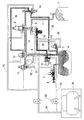
図1にこの発明に係るガス供給装置を示す。このガス供給装置は、プロパンを主成分とする液化石油ガスを貯蔵した原料ガスボンベ1と、この原料ガスボンベ1の原料ガス圧を減圧する中圧調整器2と、この中圧調整器2によって減圧された原料ガスを空気と混合して混合ガスとするベンチュリーミキサー3と、この混合ガスを一時的に貯蔵するクッションタンク4とを有し、クッションタンク4に貯蔵された混合ガスは、低圧ガバナ5及び出口バルブ6を介して一般家庭等の需要者に供給される。
FIG. 1 shows a gas supply apparatus according to the present invention. This gas supply apparatus is a raw material gas cylinder 1 storing liquefied petroleum gas mainly composed of propane, an
この原料ガスボンベ1、中圧調整器2、ベンチュリーミキサー3、及び、クッションタンク4は高圧ホース7又はガス導管8で順次接続されている。この高圧ホース7の先端には入口バルブ9が設けてあって、緊急時や原料ガスボンベ1の交換時にこの入口バルブ9を閉めてガス供給を停止する。また、ガス導管8には、原料ガスの供給を遮断する遮断弁10、この遮断弁10を制御する上下限圧遮断コントローラ11及び昇圧防止弁12、ベンチュリーミキサー3への原料ガスの供給を制御する開閉弁13、及び、この開閉弁13を制御する開閉弁コントローラ14が設けてある。また、ベンチュリーミキサー3には、加圧空気の導入を制御する空気弁15が設けてある。
The source gas cylinder 1, the
なお、ガス導管内のガス圧は場所によって異なるため、同図中においては、異なるガス圧のガス導管8ごとに異なる網掛け模様を付して、各ガス導管内のガス圧が視覚的に分かるようにしている。
In addition, since the gas pressure in the gas conduit differs depending on the location, in the same figure, the gas pressure in each gas conduit can be visually recognized by attaching a different hatching pattern to each
前記の中圧調整器2、低圧ガバナ5、昇圧防止弁12、上下限圧遮断コントローラ11、開閉弁13、開閉弁コントローラ14、及び、空気弁15には、それぞれダイヤフラム16が設けられるとともに、このダイヤフラム16のバネ室17側には、コンプレッサ18から加圧空気を送り込む空気配管19が設けられている。各バネ室17に送り込まれる加圧空気の圧力は、この空気配管19に設けたローディング用ガバナ20によって調節できる。
The
この加圧空気の圧力を高くすると、このバネ室17側からのダイヤフラム16への付勢力が大きくなり、このダイヤフラム16のダイヤフラム室21側に流入する原料ガス等のガス圧を高くした場合でも、このダイヤフラム16の両方向からの付勢力を適宜バランスし得る。このため、混合ガスのガス圧を幅広い範囲で設定することができ、利便性が高い。
When the pressure of the pressurized air is increased, the biasing force to the
また、空気弁15の空気取り込み口22にも、コンプレッサ18から加圧空気を送り込む空気配管19が別途設けられている。この加圧空気の圧力も、この空気配管19に別途設けたローディング用ガバナ20によって調節できる。このように、バネ室17に加圧空気を送り込むためのローディング用ガバナ20と、原料ガスと混合するための空気を送り込むためのローディング用ガバナ20を別々に設けることによって、混合ガスの混合比率の微調整をより正確に行い得る。このため、需要者に燃焼性の安定した高品質の混合ガスを提供することができる。
In addition, an
この実施形態では、前記のようにローディング用ガバナ20を2基設けたが、1基のローディング用ガバナ20からの加圧空気を二股に分岐して、バネ室17側及び空気取り込み口22側のそれぞれに送り込むようにすることもできる。
In this embodiment, the two
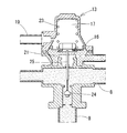
原料ガスボンベ1からの原料ガスは、まず、後述する遮断弁10を経由して、中圧調整器2に送り込まれる。この中圧調整器2は、図2に示す構成であって、そのダイヤフラム16は、バネ室17側から加圧空気及びバネ23によって付勢される一方で、ダイヤフラム室21側から原料ガス(中圧調整器2の出口側圧力)によって付勢されている。両付勢力のバランスによって弁体24の開弁度が決まり、例えば、前記出口側圧力が相対的に高くなると、この弁体24は閉弁方向に移動する。
The raw material gas from the raw material gas cylinder 1 is first fed into the
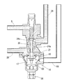
この中圧調整器2からの原料ガスは、次に開閉弁13に送り込まれる。この開閉弁13は、図3に示す構成であって、そのダイヤフラム16は、バネ室17側から加圧空気及びバネ23によって付勢される一方で、ダイヤフラム室21側から、クッションタンク4の混合ガスのガス圧、又は、中圧調整器2の出口側圧力によって付勢されている。このダイヤフラム室21側がいずれのガス圧によって付勢されるかは、後述する開閉弁コントローラ14の動作によって決まる。
The source gas from the
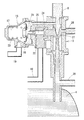
この開閉弁コントローラ14は、図4に示す構成であって、そのダイヤフラム16はバネ室17側から加圧空気及びバネ23によって付勢される一方で、ダイヤフラム室21側からクッションタンク4内の混合ガスのガス圧によって付勢されている。このダイヤフラム16と連動する弁軸25には二つの弁体24a、24bが設けられていて、同図の下側の弁体24aは、この開閉弁コントローラ14に前記混合ガスが流入するのを遮断する役目を有する一方で、上側の弁体24bは、この開閉弁コントローラ14に中圧調整器2の出口側圧力の原料ガスが流入するのを遮断する役目を有する。
The on-off
つまり、その混合ガスのガス圧が低い場合(例えば、5kPa程度)は、ダイヤフラム16が下方に変位して、この開閉弁コントローラ14及びこの出口側に接続したガス圧伝達導管26に前記混合ガスが流れ込んで開閉弁13に至る。その一方で、この混合ガスのガス圧が高い場合(例えば、15kPa程度)は、ダイヤフラム16が上方に変位して、開閉弁13と開閉弁コントローラ14の間のガス圧伝達導管26に中圧調整器2の出口圧力がガス導管8を通して開閉弁13に至る。
That is, when the gas pressure of the mixed gas is low (for example, about 5 kPa), the
前記クッションタンク4内の混合ガスのガス圧は、中圧調整器2の出口側の原料ガス圧よりも低圧である。このため、図3に示した開閉弁13のダイヤフラム室21側に前記混合ガスが導入された場合は、ダイヤフラム16が下方に変位して中圧調整器2からの原料ガスが流動し得る一方で、中圧調整器2からの原料ガスが導入された場合は、ダイヤフラム16が上方に変位して中圧調整器2からの原料ガスがこの開閉弁13の弁体24によって遮断される。
The gas pressure of the mixed gas in the
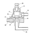
この開閉弁13からの原料ガスは、次にベンチュリーミキサー3に送られる。このベンチュリーミキサー3は、図5に示す構成であって、管状部材の内側に、ガスの流動方向に向けて原料ガスを噴射するノズル27を設けたものである。このノズル27の近傍には空気取り込み口22が設けてあって、この空気取り込み口22からコンプレッサ18からの加圧空気が取り込まれる。このベンチュリーミキサー3には空気弁15が併設されている。この空気弁15のダイヤフラム16は、バネ室17側から加圧空気及びバネ23によって付勢される一方で、ダイヤフラム室21側から中圧調整器2からの原料ガスによって付勢される。
この原料ガスのガス圧が高くなると、ダイヤフラム16が左方に変位し弁体24が開弁方向に動く。これによって、より多くの空気を取り込むことができるため、原料ガスと空気との混合比を一定に保ち得る。
The raw material gas from the on-off
When the gas pressure of the source gas increases, the
このガス供給装置には、ガス圧が異常となった際に、原料ガスの供給を遮断する遮断弁10が設けられている。
この遮断弁10は、図2に示した構成であって、そのダイヤフラム16のバネ室17側には、空気取り込み口22より取り込んだ空気が導入される一方で、ダイヤフラム室21側には、後述する上下限圧遮断コントローラ11又は昇圧防止弁12が作動した際に、それらを通して加圧空気が導入され得る。
This gas supply device is provided with a shut-off
The shut-off
例えば、空気取り込み口22より取り込んだ空気の圧力が所定値よりも低くなったときは、ダイヤフラム16とともにロック機構28が下方に変位し、リセットボタン29の係止が外れ、バネ23の付勢力によって弁体24が閉弁する。あるいは、上下限圧遮断コントローラ11又は昇圧防止弁12が作動してダイヤフラム室21に加圧空気が導入された場合にも、同様にダイヤフラム16が変位して弁体24が閉弁する。
For example, when the pressure of the air taken in from the
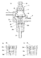
この上下限圧遮断コントローラ11は、図6に示す構成であって、そのダイヤフラム16のバネ室17側から加圧空気及びバネ23によって付勢される一方で、ダイヤフラム室21側から、中圧調整器2の出口側圧力及びバネ23によって付勢されている。この出口側圧力が所定範囲内の時は、弁体24cによりダイヤフラム室21の出口側の流路が閉弁された状態となっており、中圧調整器2からの原料ガスはこのダイヤフラム室21に留まっている(同図(a)を参照)。
The upper / lower limit
この時、原料ガスのガス圧が所定範囲を上回ると、そのガス圧によってダイヤフラム16が上方に変位し、弁体24dが開弁する。このため、この原料ガスがガス圧伝達導管26に流れ込み(同図(b)を参照)、このガス圧によって遮断弁10が作動する。その一方で、原料ガスのガス圧が所定範囲を下回ると、ダイヤフラム16が下方に変位し、弁体24cが開弁する。このため、この原料ガスがガス圧伝達導管26に流れ込み(同図(c)を参照)、このガス圧によって遮断弁10が作動する。
なお、さらに原料ガスのガス圧が低下すると(本装置を不使用の場合等)、弁体24eが閉弁して、このガス圧伝達導管26が遮断される。
At this time, when the gas pressure of the source gas exceeds a predetermined range, the
When the gas pressure of the raw material gas further decreases (when this apparatus is not used, etc.), the
また、昇圧防止弁12は、図7に示す構造であって、そのダイヤフラム16のバネ室17側から加圧空気及びバネ23によって付勢される一方で、ダイヤフラム室21側から、クッションタンク4内の混合ガスのガス圧によって付勢されている。この混合ガスのガス圧が高くなると、ダイヤフラム16が上方に変位し、弁体25が開弁する。これによって、この混合ガスがガス圧伝達導管26に流れ込んで、このガス圧によって遮断弁10が作動する。
Further, the pressure
一般的には、原料ガスボンベ1の原料ガス圧は、0.15〜1.56MPa程度であって、数戸程度の一般家庭への供給を目的とする場合は、この原料ガス圧を中圧調整器で0.095MPa程度に減圧してベンチュリーミキサーに供給し、5〜16kPa程度の圧力の混合ガスとしてクッションタンクに一時貯蔵する。この混合ガスの混合比率は、原料ガス:空気=6:4程度であって、この混合ガスの燃焼性は、都市ガス(13A)に相当する。 In general, the raw material gas pressure of the raw material gas cylinder 1 is about 0.15 to 1.56 MPa, and this raw material gas pressure is adjusted to a medium pressure for the purpose of supply to a general household of several units. The pressure is reduced to about 0.095 MPa by a vessel and supplied to a venturi mixer, and temporarily stored in a cushion tank as a mixed gas having a pressure of about 5 to 16 kPa. The mixing ratio of this mixed gas is about raw material gas: air = 6: 4, and the combustibility of this mixed gas corresponds to city gas (13A).
その一方で、供給エリアが広い場合(供給家庭数が数十戸分以上)や、導管工事等の際のように高い供給圧力(例えば、300kPa程度)が必要とされる場合は、各弁や各コントローラに設けた調節ネジ30の調節のみによっては、その供給圧力に調節できない。このような場合においても、加圧空気の圧力を変えることによって、ダイヤフラム16のバネ室17側の付勢力を自在に変えることができるので、それに対応して供給される原料ガスの圧力を高め得る。
On the other hand, when the supply area is large (the number of households to supply is more than several tens of houses), or when a high supply pressure (for example, about 300 kPa) is required, such as during pipe construction, The supply pressure cannot be adjusted only by adjusting the adjusting
このガス供給装置一式は、トラックの荷台(図示せず)に載置されているため、自然災害等が発生した際に自在にその現地に運搬することができる。このため、都市ガスの供給が停止した際に、需要者に迅速にその都市ガスの代替ガスを供給し得る。
このように必要に応じて運搬する代わりに、自然災害時に住民等が避難する避難場所にこのガス供給装置を予め設置しておいて、必要な際に適宜使用し得るようにすることもできる。
Since this gas supply device set is mounted on a truck bed (not shown), it can be freely transported to the site when a natural disaster or the like occurs. For this reason, when supply of city gas stops, a substitute gas of the city gas can be quickly supplied to a consumer.
In this way, instead of transporting as necessary, this gas supply device can be installed in advance in an evacuation area where residents and the like evacuate in the event of a natural disaster so that it can be used as needed.
1 原料ガスボンベ
2 中圧調整器
3 ベンチュリーミキサー
4 クッションタンク
5 低圧ガバナ
6 出口バルブ
7 高圧ホース
8 ガス導管
9 入口バルブ
10 遮断弁
11 上下限圧遮断コントローラ
12 昇圧防止弁
13 開閉弁
14 開閉弁コントローラ
15 空気弁
16 ダイヤフラム
17 バネ室
18 コンプレッサ
19 空気配管
20 ローディング用ガバナ
21 ダイヤフラム室
22 空気取り込み口
23 バネ
24(24a〜24e) 弁体
25 弁軸
26 ガス圧伝達導管
27 ノズル
28 ロック機構
29 リセットボタン
30 調節ネジ
31 圧力計
DESCRIPTION OF SYMBOLS 1 Raw
Claims (4)
本装置に空気を圧縮するコンプレッサ(18)を併設し、このコンプレッサ(18)から吐出された加圧空気を、前記原料ガスボンベ(1)のガス圧を減圧して前記ベンチュリーミキサー(3)に送出する中圧調整器(2)のダイヤフラム(16)のバネ室(17)に送り込んで、このダイヤフラム(16)に設けた弁体(24)を開弁方向に付勢して、前記中圧調整器(2)から前記ベンチュリーミキサー(3)への原料ガスの送出圧を高めるとともに、
前記加圧空気を、前記原料ガスと混合する空気の吸入量を調節する空気弁(15)のダイヤフラム(16)のバネ室(17)、及び、前記空気弁(15)の空気取り込み口(22)の双方にも送り込んで前記空気弁(15)の空気吸入圧を高め、前記ベンチュリーミキサー(3)で前記原料ガスと空気とを混合してクッションタンク(4)に貯蔵した際に、その貯蔵した混合ガスのガス圧を高め得るようにしつつ、その混合比率を予め決めた所定範囲内に維持し得るようにしたことを特徴とするガス供給装置。 In the gas supply apparatus in which the raw material gas of the raw material gas cylinder (1) is mixed with air by the venturi mixer (3) and stored in the cushion tank (4), and the stored mixed gas is supplied to consumers such as households. ,
The apparatus is provided with a compressor (18) for compressing air, and the compressed air discharged from the compressor (18) is sent to the venturi mixer (3) by reducing the gas pressure of the source gas cylinder (1). The intermediate pressure regulator (2) is fed into the spring chamber (17) of the diaphragm (16), and the valve body (24) provided on the diaphragm (16) is urged in the valve opening direction to adjust the intermediate pressure. While increasing the delivery pressure of the raw material gas from the vessel (2) to the venturi mixer (3),
The spring chamber (17) of the diaphragm (16) of the air valve (15) for adjusting the intake amount of the air mixed with the source gas, and the air intake port (22) of the air valve (15) ), The air intake pressure of the air valve (15) is increased, the raw material gas and air are mixed and stored in the cushion tank (4) by the venturi mixer (3), and then stored. A gas supply device characterized in that the mixing ratio can be maintained within a predetermined range while the gas pressure of the mixed gas can be increased.
前記上下限圧遮断コントローラ(11)、前記昇圧防止弁(12)、及び、前記ベンチュリーミキサー(3)の空気取り込み口(22)のそれぞれと、原料ガスボンベ(1)からの原料ガスの供給を遮断する遮断弁(10)とを接続し、前記中圧調整器(2)からの原料ガスの供給圧力、前記クッションタンク(4)内の混合ガス圧、又は、前記ベンチュリーミキサー(3)での空気吸入圧の少なくとも一つが、予め決めたそれぞれの所定範囲を外れた際に、前記遮断弁(10)を閉弁して、原料ガスボンベ(1)からの原料ガスの供給を遮断するようにしたことを特徴とする請求項1乃至3のいずれか一つに記載のガス供給装置。 An on-off valve (13) provided with the pressurized air between the intermediate pressure regulator (2) and the venturi mixer (3), and an on-off valve controller (14) for controlling on / off of the on-off valve (13) A diaphragm (16) provided on each of an upper / lower pressure cutoff controller (11) for controlling the opening / closing of the shut-off valve (10) and an anti-pressurization valve (12) for preventing over-pressurization of the cushion tank (4) The spring chamber (17), and even when the feed pressure of the raw material gas to the venturi mixer (3) is high, the valves and the controllers can operate normally,
The upper and lower pressure cutoff controller (11), the pressure increase prevention valve (12), and the air intake port (22) of the venturi mixer (3) and the supply of the source gas from the source gas cylinder (1) are shut off. The supply pressure of the raw material gas from the intermediate pressure regulator (2), the mixed gas pressure in the cushion tank (4), or the air in the venturi mixer (3) The shutoff valve (10) is closed when at least one of the suction pressures is out of the predetermined ranges, so that the supply of the source gas from the source gas cylinder (1) is shut off. The gas supply device according to any one of claims 1 to 3, wherein:
Priority Applications (1)
| Application Number | Priority Date | Filing Date | Title |
|---|---|---|---|
| JP2008161722A JP4604113B2 (en) | 2008-06-20 | 2008-06-20 | Gas supply device |
Applications Claiming Priority (1)
| Application Number | Priority Date | Filing Date | Title |
|---|---|---|---|
| JP2008161722A JP4604113B2 (en) | 2008-06-20 | 2008-06-20 | Gas supply device |
Publications (2)
| Publication Number | Publication Date |
|---|---|
| JP2010002133A true JP2010002133A (en) | 2010-01-07 |
| JP4604113B2 JP4604113B2 (en) | 2010-12-22 |
Family
ID=41583998
Family Applications (1)
| Application Number | Title | Priority Date | Filing Date |
|---|---|---|---|
| JP2008161722A Active JP4604113B2 (en) | 2008-06-20 | 2008-06-20 | Gas supply device |
Country Status (1)
| Country | Link |
|---|---|
| JP (1) | JP4604113B2 (en) |
Cited By (9)
| Publication number | Priority date | Publication date | Assignee | Title |
|---|---|---|---|---|
| WO2012101755A1 (en) * | 2011-01-25 | 2012-08-02 | 伊藤工機株式会社 | Mixed gas production device |
| JP2014181861A (en) * | 2013-03-19 | 2014-09-29 | Osaka Gas Co Ltd | Air-fuel mixture supply system |
| JP2014206300A (en) * | 2013-04-11 | 2014-10-30 | I・T・O株式会社 | Biogas utilization device |
| JP2014214882A (en) * | 2013-04-22 | 2014-11-17 | 大阪瓦斯株式会社 | Gaseous mixture supply system and gaseous mixture supply device used in gaseous mixture supply system |
| JP2014214883A (en) * | 2013-04-22 | 2014-11-17 | 大阪瓦斯株式会社 | Gaseous mixture supply system, operation method of gaseous mixture supply system and gaseous mixture supply device used for gaseous mixture supply system |
| JP2016095080A (en) * | 2014-11-14 | 2016-05-26 | 大阪瓦斯株式会社 | Gas supply device |
| JP2017207272A (en) * | 2016-05-11 | 2017-11-24 | I・T・O株式会社 | Mixture gas manufacturing device |
| JP2020148424A (en) * | 2019-03-14 | 2020-09-17 | 大阪瓦斯株式会社 | Gas supply device |
| CN113804518A (en) * | 2021-09-28 | 2021-12-17 | 武汉船用电力推进装置研究所(中国船舶重工集团公司第七一二研究所) | High-purity and ultra-pure gas high-fidelity sampling device and method |
Families Citing this family (2)
| Publication number | Priority date | Publication date | Assignee | Title |
|---|---|---|---|---|
| JP6591177B2 (en) * | 2015-03-03 | 2019-10-16 | 武陽ガス株式会社 | Gas supply device |
| CN105617898B (en) * | 2015-12-29 | 2019-01-22 | 厦门大学 | A kind of carbon dioxide gas mixture preparation facilities |
Citations (3)
| Publication number | Priority date | Publication date | Assignee | Title |
|---|---|---|---|---|
| JPH01245844A (en) * | 1988-03-28 | 1989-10-02 | Buyou Gas Kk | Method for mixing and transporting fuel gas |
| JPH06131056A (en) * | 1992-10-22 | 1994-05-13 | Tanaka Seisakusho Kk | Automatic pressure reducing valve |
| JP2005177665A (en) * | 2003-12-22 | 2005-07-07 | Ito Koki Kk | Gas supplying apparatus |
-
2008
- 2008-06-20 JP JP2008161722A patent/JP4604113B2/en active Active
Patent Citations (3)
| Publication number | Priority date | Publication date | Assignee | Title |
|---|---|---|---|---|
| JPH01245844A (en) * | 1988-03-28 | 1989-10-02 | Buyou Gas Kk | Method for mixing and transporting fuel gas |
| JPH06131056A (en) * | 1992-10-22 | 1994-05-13 | Tanaka Seisakusho Kk | Automatic pressure reducing valve |
| JP2005177665A (en) * | 2003-12-22 | 2005-07-07 | Ito Koki Kk | Gas supplying apparatus |
Cited By (13)
| Publication number | Priority date | Publication date | Assignee | Title |
|---|---|---|---|---|
| JP5762443B2 (en) * | 2011-01-25 | 2015-08-12 | I・T・O株式会社 | Mixed gas production equipment |
| CN103313778A (en) * | 2011-01-25 | 2013-09-18 | 伊藤工机株式会社 | Mixed gas production device |
| WO2012101755A1 (en) * | 2011-01-25 | 2012-08-02 | 伊藤工機株式会社 | Mixed gas production device |
| JP2014181861A (en) * | 2013-03-19 | 2014-09-29 | Osaka Gas Co Ltd | Air-fuel mixture supply system |
| JP2014206300A (en) * | 2013-04-11 | 2014-10-30 | I・T・O株式会社 | Biogas utilization device |
| JP2014214883A (en) * | 2013-04-22 | 2014-11-17 | 大阪瓦斯株式会社 | Gaseous mixture supply system, operation method of gaseous mixture supply system and gaseous mixture supply device used for gaseous mixture supply system |
| JP2014214882A (en) * | 2013-04-22 | 2014-11-17 | 大阪瓦斯株式会社 | Gaseous mixture supply system and gaseous mixture supply device used in gaseous mixture supply system |
| JP2016095080A (en) * | 2014-11-14 | 2016-05-26 | 大阪瓦斯株式会社 | Gas supply device |
| JP2017207272A (en) * | 2016-05-11 | 2017-11-24 | I・T・O株式会社 | Mixture gas manufacturing device |
| JP2020148424A (en) * | 2019-03-14 | 2020-09-17 | 大阪瓦斯株式会社 | Gas supply device |
| JP7257826B2 (en) | 2019-03-14 | 2023-04-14 | 大阪瓦斯株式会社 | gas supply |
| CN113804518A (en) * | 2021-09-28 | 2021-12-17 | 武汉船用电力推进装置研究所(中国船舶重工集团公司第七一二研究所) | High-purity and ultra-pure gas high-fidelity sampling device and method |
| CN113804518B (en) * | 2021-09-28 | 2024-04-16 | 武汉船用电力推进装置研究所(中国船舶重工集团公司第七一二研究所) | High-purity and ultra-purity gas high-fidelity sampling device and method |
Also Published As
| Publication number | Publication date |
|---|---|
| JP4604113B2 (en) | 2010-12-22 |
Similar Documents
| Publication | Publication Date | Title |
|---|---|---|
| JP4604113B2 (en) | Gas supply device | |
| KR20180077241A (en) | Ship | |
| JPH10337463A (en) | Method for backing up gas feed system or compensating and device therefor | |
| CN106906004B (en) | Pulverized coal gasification control method and pulverized coal gasification device | |
| CN114630715B (en) | Two-fluid nozzle spray device | |
| CN107847985B (en) | Water vapor sand blasting system with fixed tank pressure | |
| JP6889910B2 (en) | Mixed gas production equipment | |
| CA2697916A1 (en) | Apparatus and method for controlling the temperature of a cryogen | |
| JP4130909B2 (en) | Double fuel-fired gas turbine fuel supply system | |
| JP6536041B2 (en) | Combustion system | |
| KR101686910B1 (en) | High Pressure Pump Pressurizing System and Method for LNG Regasification System | |
| KR20230128568A (en) | Gaseous fueling system | |
| JP2006045327A (en) | Method and apparatus for controlling dilution of calorific value of natural gas | |
| JP5229752B2 (en) | Natural gas dilution heat adjustment method | |
| KR20130071366A (en) | Apparatus and method for supplying liquefied gas | |
| JP4962853B2 (en) | BOG compression equipment and method | |
| JP6453054B2 (en) | Gas supply device | |
| JP2010001355A (en) | System for controlling calorie of natural gas and method for controlling calorie | |
| KR101307495B1 (en) | Gas supply apparatus | |
| CN114507550B (en) | Pressure control system of voltage transformation device | |
| CN114889796A (en) | Inerting control system and method for fuel pipeline | |
| CN110220118B (en) | Liquefied compressed natural gas high-pressure plunger pump pipeline system | |
| JP6582364B2 (en) | Boiler system | |
| JP4875442B2 (en) | Engine gas fuel supply device | |
| CN109485277B (en) | Natural gas calcination equipment and method for lime kiln |
Legal Events
| Date | Code | Title | Description |
|---|---|---|---|
| A977 | Report on retrieval |
Free format text: JAPANESE INTERMEDIATE CODE: A971007 Effective date: 20100603 |
|
| A131 | Notification of reasons for refusal |
Free format text: JAPANESE INTERMEDIATE CODE: A131 Effective date: 20100615 |
|
| A521 | Written amendment |
Free format text: JAPANESE INTERMEDIATE CODE: A523 Effective date: 20100805 |
|
| TRDD | Decision of grant or rejection written | ||
| A01 | Written decision to grant a patent or to grant a registration (utility model) |
Free format text: JAPANESE INTERMEDIATE CODE: A01 Effective date: 20100907 |
|
| A01 | Written decision to grant a patent or to grant a registration (utility model) |
Free format text: JAPANESE INTERMEDIATE CODE: A01 |
|
| A61 | First payment of annual fees (during grant procedure) |
Free format text: JAPANESE INTERMEDIATE CODE: A61 Effective date: 20101004 |
|
| FPAY | Renewal fee payment (event date is renewal date of database) |
Free format text: PAYMENT UNTIL: 20131008 Year of fee payment: 3 |
|
| R150 | Certificate of patent or registration of utility model |
Free format text: JAPANESE INTERMEDIATE CODE: R150 Ref document number: 4604113 Country of ref document: JP Free format text: JAPANESE INTERMEDIATE CODE: R150 |
|
| R250 | Receipt of annual fees |
Free format text: JAPANESE INTERMEDIATE CODE: R250 |
|
| R250 | Receipt of annual fees |
Free format text: JAPANESE INTERMEDIATE CODE: R250 |
|
| R250 | Receipt of annual fees |
Free format text: JAPANESE INTERMEDIATE CODE: R250 |
|
| R250 | Receipt of annual fees |
Free format text: JAPANESE INTERMEDIATE CODE: R250 |
|
| R250 | Receipt of annual fees |
Free format text: JAPANESE INTERMEDIATE CODE: R250 |
|
| R250 | Receipt of annual fees |
Free format text: JAPANESE INTERMEDIATE CODE: R250 |
|
| R250 | Receipt of annual fees |
Free format text: JAPANESE INTERMEDIATE CODE: R250 |
|
| R250 | Receipt of annual fees |
Free format text: JAPANESE INTERMEDIATE CODE: R250 |
|
| R250 | Receipt of annual fees |
Free format text: JAPANESE INTERMEDIATE CODE: R250 |