JP2010002059A - Refractory spraying method and device - Google Patents
Refractory spraying method and device Download PDFInfo
- Publication number
- JP2010002059A JP2010002059A JP2008158659A JP2008158659A JP2010002059A JP 2010002059 A JP2010002059 A JP 2010002059A JP 2008158659 A JP2008158659 A JP 2008158659A JP 2008158659 A JP2008158659 A JP 2008158659A JP 2010002059 A JP2010002059 A JP 2010002059A
- Authority
- JP
- Japan
- Prior art keywords
- nozzle
- refractory
- spraying
- angle
- wall
- Prior art date
- Legal status (The legal status is an assumption and is not a legal conclusion. Google has not performed a legal analysis and makes no representation as to the accuracy of the status listed.)
- Granted
Links
- 238000005507 spraying Methods 0.000 title claims abstract description 60
- 239000002184 metal Substances 0.000 claims abstract description 14
- 239000007921 spray Substances 0.000 claims description 42
- 238000000034 method Methods 0.000 claims description 5
- 230000001788 irregular Effects 0.000 description 9
- 238000005259 measurement Methods 0.000 description 9
- 238000001514 detection method Methods 0.000 description 7
- 230000003028 elevating effect Effects 0.000 description 5
- 229910000831 Steel Inorganic materials 0.000 description 3
- 239000011819 refractory material Substances 0.000 description 3
- 239000010959 steel Substances 0.000 description 3
- 238000004364 calculation method Methods 0.000 description 2
- 238000010276 construction Methods 0.000 description 2
- 230000001154 acute effect Effects 0.000 description 1
- 238000006073 displacement reaction Methods 0.000 description 1
- 238000004079 fireproofing Methods 0.000 description 1
- 238000009434 installation Methods 0.000 description 1
- 239000000463 material Substances 0.000 description 1
- 238000012986 modification Methods 0.000 description 1
- 230000004048 modification Effects 0.000 description 1
- 238000011179 visual inspection Methods 0.000 description 1
- 239000002699 waste material Substances 0.000 description 1
Images


Landscapes
- Application Of Or Painting With Fluid Materials (AREA)
- Casting Support Devices, Ladles, And Melt Control Thereby (AREA)
- Spray Control Apparatus (AREA)
- Furnace Housings, Linings, Walls, And Ceilings (AREA)
Abstract
【課題】溶融金属用容器の内壁の位置や形状に応じて、常に好適な位置および角度で耐火物を吹き付けることができる耐火物吹き付け方法および吹き付け装置を提供する。
【解決手段】溶融金属用容器10の内壁の表面形状を計測して容器10内面の展開図上に表示するとともに、耐火物を吹き付けるノズル25の位置および角度をリアルタイムで検出してノズル25による耐火物吹き付け点を算出し、展開図上における吹き付け点を表示器45に表示する。展開図と表示器45とを対比しながらノズル25の位置および角度を調整する。
【選択図】図1
A refractory spraying method and a spraying device capable of spraying a refractory at a suitable position and angle at all times according to the position and shape of an inner wall of a molten metal container.
The surface shape of the inner wall of a molten metal container 10 is measured and displayed on a developed view of the inner surface of the container 10, and the position and angle of the nozzle 25 for spraying the refractory are detected in real time and the fire resistance by the nozzle 25 is achieved. An object spraying point is calculated, and the spraying point on the development view is displayed on the display unit 45. The position and angle of the nozzle 25 are adjusted while comparing the developed view with the display 45.
[Selection] Figure 1
Description
本発明は、製鉄所等において、取鍋、溶銑鍋、溶鋼鍋、タンディッシュ等、溶銑や溶鋼等の溶融金属を収容する各種容器の内壁に不定形耐火物を吹き付け施工により補修する際の耐火物吹き付け方法およびその装置に関するものである。 The present invention relates to fireproofing at the time of repairing by spraying an irregular shaped refractory on the inner wall of various containers containing molten metal such as hot metal or molten steel, such as ladle, hot metal ladle, molten steel pan, tundish, etc. The present invention relates to an object spraying method and an apparatus therefor.
従来、製鉄所等で使用される溶融金属を収容する溶融金属用容器(以下、単に容器と称することもある)の内壁に、耐火物層を新規施工または補修するために、耐火物の吹き付けが行われている。これは、長尺の吹き付けノズルを吹き付け場所へ挿入し、内壁面にノズルを近づけて不定形耐火物を吹き付ける方法である。即ち、作業者が、内壁の状態を肉眼で判断しながら、吹き付けノズルを直接手で持つか或いは遠隔操作により内壁に近づけて、不定形耐火物をノズルから吐出させる。 Conventionally, in order to newly construct or repair a refractory layer on the inner wall of a molten metal container (hereinafter sometimes simply referred to as a container) containing molten metal used in steelworks, refractory spraying has been performed. Has been done. This is a method in which a long spray nozzle is inserted into a spray place, and the nozzle is brought close to the inner wall surface to spray an irregular refractory. In other words, the operator holds the spray nozzle directly by hand while judging the state of the inner wall with the naked eye, or closes it to the inner wall by remote operation, and discharges the irregular refractory from the nozzle.
このような不定形耐火物の吹き付けは、ノズルから吐出した不定形耐火物が内壁から跳ね返るリバウンドを抑えることが必要である。リバウンドは、ノズル先端と内壁との距離や吹き付け角度が適正でない場合に起こることが多いが、手動による吹き付けでは、目視によってこれらの距離や角度を調整しなければならず、作業者の経験や勘等の熟練技術を要する。そのため、作業者により吹き付け作業時間および仕上がりの表面状態に差が生じることがある。 Such spraying of the irregular refractory requires that the irregular refractory discharged from the nozzle is prevented from rebounding from the inner wall. Rebound often occurs when the distance between the nozzle tip and the inner wall and the spray angle are not appropriate, but with manual spray, these distances and angles must be adjusted by visual inspection, and the operator's experience and Such skill is required. Therefore, there may be a difference between the spraying work time and the finished surface condition depending on the operator.
また、極めて高温の熱間においては、作業者が容器に近づくことが困難であるため、小窓を設けた防熱板を介して作業したり、離れた位置から遠隔操作により吹き付けノズルを挿入することになる。前者においては、死角が多く、内壁全体を観察することは難しい。また、後者においては、内壁から離れることにより、正確な凹凸等を視認しにくい。したがって、ノズルと内壁との距離や不定形耐火物の吹き付け角度が一定でなく、作業時の条件により吹き付け状況が異なる。 Also, it is difficult for workers to get close to the container in extremely hot heat, so work through a heat insulating plate with a small window or insert a spray nozzle by remote control from a remote location. become. In the former, there are many blind spots, and it is difficult to observe the entire inner wall. Moreover, in the latter, it is difficult to visually recognize accurate irregularities and the like by moving away from the inner wall. Therefore, the distance between the nozzle and the inner wall and the spraying angle of the irregular refractory are not constant, and the spraying situation varies depending on the working conditions.
このような課題を解決するため、ノズルを有する操作棒に設けたレーザ距離計の計測値を基に、ノズルの位置や方向を制御しながら自動的に不定形耐火物の吹き付けを行う吹き付け装置が、例えば特許文献1に開示されている。
In order to solve such a problem, a spraying device that automatically sprays an amorphous refractory while controlling the position and direction of the nozzle based on the measurement value of a laser distance meter provided on an operation rod having a nozzle. For example, it is disclosed in
しかしながら、前記特許文献1は、ノズルの位置や方向および吹き付けを行う溶損位置をリアルタイムで把握するシステムを有していない。したがって、耐火物の吹き付け箇所に応じて、正確にノズルの位置および角度が所定の条件を満たしているかどうかを確認しながら制御することが困難である、という問題点がある。
However, the
本発明の目的は、溶融金属用容器の内壁の位置や形状に応じて、常に好適な位置および角度で耐火物を吹き付けることができる耐火物吹き付け方法および吹き付け装置を提供することにある。 An object of the present invention is to provide a refractory spraying method and a spraying device that can always spray a refractory at a suitable position and angle according to the position and shape of the inner wall of a molten metal container.
上記問題を解決するため、本発明は、溶融金属用容器の内壁に耐火物を吹き付ける耐火物吹き付け方法であって、前記内壁の表面形状を計測して前記容器内面の展開図上に表示するとともに、ノズルの位置および角度をリアルタイムで検出して前記ノズルによる耐火物吹き付け点を算出し、前記展開図上における前記吹き付け点を表示器に表示して、前記展開図と前記表示器とを対比しながら前記ノズルの位置および角度を調整することを特徴とする耐火物吹き付け方法を提供する。リアルタイムで吹き付け時のノズルの位置および角度を把握しながら制御するため、耐火物吹き付け箇所の位置や形状に応じて、常に好適な状態で耐火物が吹き付けられる。 In order to solve the above-mentioned problem, the present invention is a refractory spraying method for spraying a refractory to the inner wall of a molten metal container, and measures the surface shape of the inner wall and displays it on a developed view of the inner surface of the container. The position and angle of the nozzle is detected in real time to calculate the refractory spray point by the nozzle, the spray point on the development view is displayed on a display, and the development view and the display are compared. While providing a refractory spraying method, the position and angle of the nozzle are adjusted. Since control is performed while grasping the position and angle of the nozzle at the time of spraying in real time, the refractory is sprayed in a suitable state at all times according to the position and shape of the refractory spraying part.
前記展開図は、X−Y座標平面上に表示されていることが好ましい。さらに、耐火物吹き付け作業開始時に、前記ノズルの基準点通過を検知した後、前記基準点に対する前記ノズルの位置を検出することが好ましい。 The developed view is preferably displayed on an XY coordinate plane. Furthermore, it is preferable to detect the position of the nozzle with respect to the reference point after detecting passage of the reference point of the nozzle at the start of the refractory spraying operation.
また、本発明によれば、溶融金属用容器の内壁に耐火物を吹き付ける耐火物吹き付け装置であって、前記内壁の形状を計測して前記容器内面の展開図上に表示する計測器と、位置および角度を調整可能なノズルの位置および角度をリアルタイムで検出して前記ノズルによる耐火物吹き付け点を算出する手段と、前記展開図上における前記吹き付け点を表示する表示器を備えていることを特徴とする耐火物吹き付け装置が提供される。 Further, according to the present invention, there is provided a refractory spraying device for spraying a refractory on the inner wall of a molten metal container, the measuring instrument for measuring the shape of the inner wall and displaying it on the developed view of the inner surface of the container, And means for detecting the position and angle of the nozzle whose angle can be adjusted in real time to calculate a refractory spray point by the nozzle, and a display for displaying the spray point on the development view. A refractory spraying device is provided.
本発明によれば、常に好適な状態で耐火物が吹き付けられるので、耐火物が無駄なく且つ強固に内壁に堆積し、耐久性に優れた施工体が形成される。したがって、材料コストを低減させることができ、吹き付けの頻度も削減できる。 According to the present invention, since the refractory is sprayed in a suitable state at all times, the refractory is deposited on the inner wall without waste and firmly, and a construction body excellent in durability is formed. Therefore, material cost can be reduced and the frequency of spraying can also be reduced.
以下、本発明の実施の形態を、図を参照して説明する。 Hereinafter, embodiments of the present invention will be described with reference to the drawings.
図1は、本発明にかかる耐火物吹き付け装置1の概略を示す。尚、図1の例において、不定形耐火物を吹き付ける溶融金属用容器は、タンディッシュ10とする。
FIG. 1 shows an outline of a
図1に示すように、タンディッシュ10の設置位置に隣接して、地上にレール11が敷設され、レール11上を台車12が走行可能に載置されている。台車12には台車走行モータ13が設置され、台車走行モータ13から、駆動軸を介して車輪14に回転力が伝達され、台車12がレール11に沿って走行する。レール11は、タンディッシュ10の側方に、タンディッシュ10の長手方向に沿って敷設され、台車12はタンディッシュ10の長手方向に沿って移動可能となっている。レール11に近接する地上の所定位置には、基準位置を示す基準点が設けられる。基準点には、例えばストライカー(不図示)が設けられ、台車12に取り付けられたリミットスイッチ15がストライカーに接触することにより、リミットスイッチ15からの検出信号が制御装置41に入力される。制御装置41は、入力された検出信号に基づいて、台車12がタンディッシュ10長手方向の基準位置に到達したことを検知する。基準点は、例えば、タンディッシュ10の長手方向(側方)から見て、後述するノズル25の回転中心位置がタンディッシュ10の内壁の片端に到達したときにリミットスイッチ15が接触する位置に設けられる。
As shown in FIG. 1, a
台車12上には支柱21が立設されており、支柱21には、昇降フレーム22を介してランス23が装着されている。ランス23は、支柱21上部に設けられたランス昇降モータ24により、昇降フレーム22を介して、上下方向に昇降可能である。ランス23は、昇降フレーム22から下方に向けて垂設され、下方の先端にノズル25を備えている。ランス23内部には、ノズル25へ不定形耐火物を搬送する耐火物供給ホース26が設けられている。耐火物供給ホース26には、図示しない耐火物圧送ポンプを介して不定形耐火物が搬送される。耐火物圧送ポンプは、例えば台車12上に積載される。
A
ランス23上部には、ランス回転モータ31とノズル回動モータ32が設けられ、これらは耐熱・防塵用のカバー33で覆われている。ランス回転モータ31によって、ランス23は自身の軸線を中心として回転可能である。また、ノズル回動モータ32によって、ノズル25は、図1の水平方向から垂直下向きまで、約90度の範囲で向きを回動し、吹き付け方向を変えることができる。
A
支柱21には、ランス昇降基準点が設定され、昇降フレーム22に設けられた昇降位置検出センサ36によって、昇降フレーム22の位置が認識される。昇降フレーム22は、昇降位置検出センサ36による検出信号に基づいて、ランス昇降モータ24により支柱21に沿って上下方向に昇降制御され、それに伴ってランス23が上下移動する。
A lance lift reference point is set on the
台車走行モータ13、ランス昇降モータ24、ランス回転モータ31、及びノズル回動モータ32は、コンピュータを内蔵する制御装置41を介して駆動制御される。これらの出力調整は、自動的に行われてもよいし、例えばオペレータがジョイスティック等を操作することにより行われてもよい。この際、オペレータは、例えば台車12上で、この操作を行う。
The
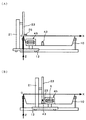
さらに、図2(A)に示すように、タンディッシュ10の内部全体が見える高所に計測器42が設けられ、タンディッシュ10の内壁の表面形状を例えばレーザにより計測する。計測結果は、図2(B)に示すように、タンディッシュ10内壁の表面の形状が平面状の展開図43でCT画面上に表示され、例えばプリンタで印刷することも可能である。展開図43はX−Y座標平面上に表示され、任意の点を座標で示すことができる。図2(A)に示すように、タンディッシュ10内部の耐火物層に損傷箇所44がある場合には、その損傷箇所44の範囲が平面状の展開図43上に表示される。
Further, as shown in FIG. 2A, a
さらに、本発明においては、ノズル25の位置および角度を検知して、吹き付け点の位置を表示可能な表示器45を装備している。吹き付け点は、図2(B)と同様の展開図上に表示される。表示器45は、例えば台車12上に設置される。吹き付け点は、以下のように求められる。
Further, in the present invention, a
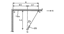
吹き付け点Sの水平方向の位置は、以下のように算出される。タンディッシュ10の長手方向をX方向とすると、図3に示すように、前述のリミットスイッチ15が動作した位置である基準点Oから、ノズル25による吹き付け点SまでのX方向の距離xは、基準点Oからの台車12の走行距離x0と、ランスの回転角度によるX方向のずれx1との和
x=x0+x1
で求められる。x0は、台車走行モータ13(図1)に取り付けられた回転計(図示省略)で計測された回転数から求められる。x1は、ノズル25の回転中心Nとタンディッシュ10の側面10aとの水平距離をLx、ランス23の回転角度をθxとすると、
x1=Lx×tanθx
である。θxは、ランス回転モータ31(図1)の回転数から求められる。したがって、吹き付け点SのX方向の位置xは、
x=x0+Lx×tanθx
で算出される。
The horizontal position of the spray point S is calculated as follows. Assuming that the longitudinal direction of the
Is required. x 0 is determined from the rotational speed measured by the
x 1 = Lx × tan θx
It is. θx is obtained from the rotational speed of the lance rotation motor 31 (FIG. 1). Therefore, the position x in the X direction of the spray point S is
x = x 0 + Lx × tan θx
Is calculated by
吹き付け点Sの鉛直方向(Z方向)の位置は、以下のように算出される。基準点Oをタンディッシュ10の上端とすると、図4に示すように、基準点Oからノズル25による吹き付け点SまでのZ方向の距離zは、基準点Oからのランス23の下降距離z0と、ノズル25の回転角度によるZ方向のずれz1との和
z=z0+z1
で求められる。z0は、昇降位置検出センサ36(図1)により検出される。z1は、タンディッシュ10の側面10aの法線方向におけるノズルの回転中心Nとの距離をLz、ノズルの回転角度をθzとすると、
z1=Lz×sinθz
である。θzは、ノズル回動モータ32の回転数から求められる。したがって、吹き付け点SのZ方向の位置zは、
z=z0+Lz×sinθz
で算出される。
The position of the spray point S in the vertical direction (Z direction) is calculated as follows. Assuming that the reference point O is the upper end of the
Is required. z 0 is detected by the lift position detection sensor 36 (FIG. 1). z 1 is Lz as the distance from the rotation center N of the nozzle in the normal direction of the side surface 10a of the
z 1 = Lz × sin θz
It is. θz is obtained from the number of rotations of the
z = z 0 + Lz × sin θz
Is calculated by
このようにして、台車12の走行距離およびランス23の昇降距離から算出されるノズル25の回転中心Nの位置と、ランス23およびノズル25の回転角度とを検出することにより、吹き付け点Sの座標が算出され、表示器45において、その座標が表示される。
In this way, by detecting the position of the rotation center N of the
なお、タンディッシュ10の内壁の形状は、計測時に制御装置41内に記憶されるので、側面10aの高さ方向の各位置の傾きに対して、ノズル25の吹き付け方向が直角になるノズル25の回転角度および回転中心位置を、タンディッシュ10の高さ方向の各位置に応じて決めておくことができる。即ち、補修等を行う耐火物吹き付け位置の座標に応じて、ランス23の昇降距離即ちノズル25の回転中心NのZ方向の位置と、ノズル25の回転角度とを予めプログラムしておくことにより、Z方向において、常に側面10aに対して垂直に不定形耐火物を吹き付けることができる。さらに、タンディッシュ10内の耐火物層の仕上がり時の表面における各位置の角度を予め設定し、制御装置41に記憶させて制御することにより、仕上がり状態を一定に保つことができる。
Since the shape of the inner wall of the
次に、上記の吹き付け装置1による耐火物吹き付け方法の手順を説明する。
Next, the procedure of the refractory spraying method by the
先ず、計測器42でタンディッシュ10内壁の表面形状を計測し、損傷箇所の有無等、耐火物を吹き付ける位置を調べる。損傷箇所等がある場合には、計測結果をプリントアウトする。計測結果は、例えば図2(B)に示すように、展開図43上に表示される。
First, the surface shape of the inner wall of the
オペレータは、図5(A)に示すように、台車12を基準点Oまで走行させる。図示の例では、タンディッシュ10の長手方向(X方向)において、ノズル25の回転中心位置がタンディッシュ10の端部に一致したときに、台車12が基準点Oに到達したものとする。その後、ノズル25の回転中心位置および角度から算出された吹き付け点の座標を、リアルタイムで表示器45に表示させる。オペレータは、図2(B)で示した内壁の測定結果を照合しながら、表示器45の表示に従って、台車走行モータ13、ランス昇降モータ24、ランス回転モータ31、ノズル回動モータ32の出力を調整する。図5(B)に示すように、ノズル25が適切な位置および角度に達し、表示器45に表示された吹き付け点Sが図2(B)の損傷箇所44と一致したところで、不定形耐火物の吹き付けを行う。なお、吹き付け作業を開始する毎に、台車12の基準点Oへの到達を検出することによって、台車12のスリップ等によりノズル25の位置がずれるのを防ぎ、より正確な位置および角度からの吹き付けが可能となる。
The operator causes the
なお、一般に、不定形耐火物の吹き付けにおいては、吹き付け位置とノズル25との距離を所定の範囲に保つことが好ましい。また、耐火物の吹き付け角度は、吹き付け位置に対して直角またはそれに近い角度で行うことが好ましい。本発明を実施するにあたり、例えば、吹き付け位置の高さ方向に対しては直角に吹き付け、水平方向に対しては、ランス23の回転と台車12の移動とを併用し、吹き付け角度が鋭角になり過ぎないように制御する。即ち、基本的な吹き付け手順として、吹き付け位置(損傷箇所)の座標が算出されると、先ず、上下方向において、吹き付け位置の最上部とノズル25の回転中心位置がほぼ一致するようにランス23を下降させる。このときのノズル25の回転角度は、水平またはそれに近い角度となる。吹き付け位置が下方へ延びている場合には、ノズル25を回転させて下方向へ向けるか、吹き付け位置が広範囲にわたる場合には、ノズル25先端と吹き付け位置との距離が大きくなり過ぎないように、ランス23を下降させながらノズル25を適宜回転させる。吹き付け位置の水平方向に対しては、ランス23を回転させることによりノズル25先端の向きを変えて吹き付け、吹き付け位置が広範囲にわたる場合には、吹き付け角度が小さくなり過ぎないように、台車12をレール11に沿って走行させるとともに適宜ランス23を回転させて吹き付けを行う。以上の調整は、表示器45によりリアルタイムでノズル25の位置および角度を確認することにより、正確に制御され、好適な吹き付けが行われる。
In general, it is preferable to keep the distance between the spraying position and the
吹き付け補修後に、計測器42でタンディッシュ10の内壁の形状を再び計測することにより、吹き付け施工面に塗布された耐火物の厚さを計測し、展開図に表示して、所定の厚さに施工されたかどうかを確認することもできる。
After the spray repair, the shape of the inner wall of the
以上、本発明の好適な実施形態について説明したが、本発明はかかる例に限定されない。当業者であれば、特許請求の範囲に記載された技術的思想の範疇内において、各種の変更例または修正例に想到しうることは明らかであり、それらについても当然に本発明の技術的範囲に属するものと了解される。例えば、上記の実施形態においては、最初に計測したタンディッシュ10内壁の形状を示すデータを印刷して、その印刷物と、実際のノズル25の位置から算出される吹き付け点(表示器45)とを比較するものとしたが、タンディッシュ10内壁の形状と吹き付け点とを表示器に並べて或いは重ねて表示し、ノズル25の制御を行ってもよい。また、制御装置41により算出されたノズル25の位置および角度を、手動操作ではなく、各モータ13,24,31,32を制御装置41が自動制御し、補修後のタンディッシュ内壁の表面形状をオペレータが表示器45で確認するようにしてもよい。
As mentioned above, although preferred embodiment of this invention was described, this invention is not limited to this example. It is obvious for those skilled in the art that various changes or modifications can be conceived within the scope of the technical idea described in the claims. It is understood that it belongs to. For example, in the above-described embodiment, data indicating the shape of the inner wall of the
本発明は、製鉄所等で用いられる溶銑や溶鋼等を収容する各種容器や炉の内壁に耐火物を吹き付ける際の耐火物吹き付け方法および装置に適用できる。 INDUSTRIAL APPLICABILITY The present invention can be applied to a refractory spraying method and apparatus for spraying a refractory on various containers for containing hot metal, molten steel, and the like used in steelworks and the inner wall of a furnace.
1 吹き付け装置
10 タンディッシュ
10a 側面
11 レール
12 台車
13 台車走行モータ
14 車輪
15 リミットスイッチ
21 支柱
22 昇降フレーム
23 ランス
24 ランス昇降モータ
25 ノズル
26 耐火物供給ホース
31 ランス回転モータ
32 ノズル回動モータ
33 カバー
36 昇降位置検出センサ
41 制御装置
42 計測器
43 展開図
44 損傷箇所
45 表示器
N 回転中心
O 基準点
S 吹き付け点
DESCRIPTION OF
Claims (4)
前記内壁の表面形状を計測して前記容器内面の展開図上に表示するとともに、
ノズルの位置および角度をリアルタイムで検出して前記ノズルによる耐火物吹き付け点を算出し、前記展開図上における前記吹き付け点を表示器に表示して、前記展開図と前記表示器とを対比しながら前記ノズルの位置および角度を調整することを特徴とする、耐火物吹き付け方法。 A refractory spraying method for spraying a refractory on the inner wall of a molten metal container,
While measuring the surface shape of the inner wall and displaying it on the development of the inner surface of the container,
Detecting the position and angle of the nozzle in real time to calculate the refractory spray point by the nozzle, displaying the spray point on the development view on a display, and comparing the development view and the display A method for spraying a refractory, wherein the position and angle of the nozzle are adjusted.
前記内壁の形状を計測して前記容器内面の展開図上に表示する計測器と、位置および角度を調整可能なノズルの位置および角度をリアルタイムで検出して前記ノズルによる耐火物吹き付け点を算出する手段と、前記展開図上における前記吹き付け点を表示する表示器を備えていることを特徴とする、耐火物吹き付け装置。 A refractory spraying device for spraying a refractory on the inner wall of a molten metal container,
A measuring instrument that measures the shape of the inner wall and displays it on the developed view of the inner surface of the container, and detects the position and angle of the nozzle whose position and angle can be adjusted in real time to calculate the refractory spray point by the nozzle Means and a display device for displaying the spray point on the development view.
Priority Applications (1)
| Application Number | Priority Date | Filing Date | Title |
|---|---|---|---|
| JP2008158659A JP5549057B2 (en) | 2008-06-18 | 2008-06-18 | Refractory spraying method and spraying apparatus |
Applications Claiming Priority (1)
| Application Number | Priority Date | Filing Date | Title |
|---|---|---|---|
| JP2008158659A JP5549057B2 (en) | 2008-06-18 | 2008-06-18 | Refractory spraying method and spraying apparatus |
Publications (2)
| Publication Number | Publication Date |
|---|---|
| JP2010002059A true JP2010002059A (en) | 2010-01-07 |
| JP5549057B2 JP5549057B2 (en) | 2014-07-16 |
Family
ID=41583927
Family Applications (1)
| Application Number | Title | Priority Date | Filing Date |
|---|---|---|---|
| JP2008158659A Active JP5549057B2 (en) | 2008-06-18 | 2008-06-18 | Refractory spraying method and spraying apparatus |
Country Status (1)
| Country | Link |
|---|---|
| JP (1) | JP5549057B2 (en) |
Cited By (6)
| Publication number | Priority date | Publication date | Assignee | Title |
|---|---|---|---|---|
| JP2016090140A (en) * | 2014-11-05 | 2016-05-23 | 大同特殊鋼株式会社 | Fusion furnace |
| JP2017536981A (en) * | 2014-11-26 | 2017-12-14 | グラス・サーフェス・テクノロジーGlass Surface Technology | Method and apparatus for coating the inner surface of a container and container obtained using such a method |
| KR101887606B1 (en) * | 2017-04-19 | 2018-08-10 | 주식회사 포스코 | Vessel facilies, base metal removal method and refractories reinforcing method of the same |
| JP2020065959A (en) * | 2018-10-22 | 2020-04-30 | 鹿島建設株式会社 | Fireproof coating method |
| KR20200108421A (en) * | 2018-11-01 | 2020-09-18 | 푸양 펑셔널 머테리얼스 컴퍼니., 리미티드. | Spray gun device and ladle lining refractory material injection device |
| JP2021147908A (en) * | 2020-03-19 | 2021-09-27 | 積水ハウス株式会社 | Residential exterior wall panel painting device |
Citations (7)
| Publication number | Priority date | Publication date | Assignee | Title |
|---|---|---|---|---|
| JPS51147510A (en) * | 1975-06-13 | 1976-12-17 | Nippon Steel Corp | Method of measuring working surface profile of refractory lining vessels and of mending the surface |
| JPS58115291A (en) * | 1981-12-28 | 1983-07-08 | 川崎製鉄株式会社 | Detector for state of breaking due to melting of refractory of molten-metal vessel |
| JPS59145479A (en) * | 1983-02-05 | 1984-08-20 | 住友金属工業株式会社 | Furnace refractory lining method |
| JPH0225687A (en) * | 1988-07-13 | 1990-01-29 | Nippon Steel Corp | Repairing method and repairing device for vessel applied with lining for molten metal |
| JPH074860A (en) * | 1993-06-18 | 1995-01-10 | Nippon Steel Corp | Casting method for cleaning cores for lining molding |
| JPH07218148A (en) * | 1994-02-01 | 1995-08-18 | Nippon Steel Corp | Refractory thermal spray repair method and equipment |
| JP2002005579A (en) * | 2000-06-23 | 2002-01-09 | Nkk Corp | Device for spraying refractory |
-
2008
- 2008-06-18 JP JP2008158659A patent/JP5549057B2/en active Active
Patent Citations (7)
| Publication number | Priority date | Publication date | Assignee | Title |
|---|---|---|---|---|
| JPS51147510A (en) * | 1975-06-13 | 1976-12-17 | Nippon Steel Corp | Method of measuring working surface profile of refractory lining vessels and of mending the surface |
| JPS58115291A (en) * | 1981-12-28 | 1983-07-08 | 川崎製鉄株式会社 | Detector for state of breaking due to melting of refractory of molten-metal vessel |
| JPS59145479A (en) * | 1983-02-05 | 1984-08-20 | 住友金属工業株式会社 | Furnace refractory lining method |
| JPH0225687A (en) * | 1988-07-13 | 1990-01-29 | Nippon Steel Corp | Repairing method and repairing device for vessel applied with lining for molten metal |
| JPH074860A (en) * | 1993-06-18 | 1995-01-10 | Nippon Steel Corp | Casting method for cleaning cores for lining molding |
| JPH07218148A (en) * | 1994-02-01 | 1995-08-18 | Nippon Steel Corp | Refractory thermal spray repair method and equipment |
| JP2002005579A (en) * | 2000-06-23 | 2002-01-09 | Nkk Corp | Device for spraying refractory |
Cited By (9)
| Publication number | Priority date | Publication date | Assignee | Title |
|---|---|---|---|---|
| JP2016090140A (en) * | 2014-11-05 | 2016-05-23 | 大同特殊鋼株式会社 | Fusion furnace |
| JP2017536981A (en) * | 2014-11-26 | 2017-12-14 | グラス・サーフェス・テクノロジーGlass Surface Technology | Method and apparatus for coating the inner surface of a container and container obtained using such a method |
| KR101887606B1 (en) * | 2017-04-19 | 2018-08-10 | 주식회사 포스코 | Vessel facilies, base metal removal method and refractories reinforcing method of the same |
| JP2020065959A (en) * | 2018-10-22 | 2020-04-30 | 鹿島建設株式会社 | Fireproof coating method |
| JP7141909B2 (en) | 2018-10-22 | 2022-09-26 | 鹿島建設株式会社 | Fireproof coating method |
| KR20200108421A (en) * | 2018-11-01 | 2020-09-18 | 푸양 펑셔널 머테리얼스 컴퍼니., 리미티드. | Spray gun device and ladle lining refractory material injection device |
| KR102469935B1 (en) | 2018-11-01 | 2022-11-22 | 푸양 펑셔널 머테리얼스 컴퍼니., 리미티드. | Spray gun device and ladle lining refractory material spray device |
| JP2021147908A (en) * | 2020-03-19 | 2021-09-27 | 積水ハウス株式会社 | Residential exterior wall panel painting device |
| JP7413869B2 (en) | 2020-03-19 | 2024-01-16 | 積水ハウス株式会社 | Painting equipment for residential exterior wall panels |
Also Published As
| Publication number | Publication date |
|---|---|
| JP5549057B2 (en) | 2014-07-16 |
Similar Documents
| Publication | Publication Date | Title |
|---|---|---|
| JP5549057B2 (en) | Refractory spraying method and spraying apparatus | |
| US8821694B2 (en) | Method and device for the positioning of operating units of a coal filling cart at the filling openings of a coke oven | |
| EP2558816B1 (en) | System for measuring the inner space of a container and method of performing the same | |
| JP6289226B2 (en) | Temperature furnace sampling equipment for arc furnace | |
| KR101491204B1 (en) | Marker for grinding and cleaning | |
| JP4559346B2 (en) | Support construction method and support construction system | |
| US6440355B1 (en) | Apparatus for measuring bath level in a basic oxygen furnace to determine lance height adjustment | |
| JP2002005579A (en) | Device for spraying refractory | |
| JP5141851B2 (en) | Method and apparatus for measuring remaining amount of refractory in molten steel pan | |
| JP3018943B2 (en) | Blast furnace wall profile measurement method and apparatus | |
| JPH08178905A (en) | Diagnosis of outer wall | |
| KR102359238B1 (en) | Deck and work method | |
| KR20200003581A (en) | Wire rope damage position detecting appratus, crane having the same, and wire rope damage position detecting method | |
| JP2007118165A (en) | Ink position recording device | |
| JPS5970461A (en) | Method and device for spraying on tundish | |
| JP5217389B2 (en) | Method and apparatus for hot spraying refractories | |
| JPH05256584A (en) | Method and apparatus for repairing damaged part on furnace wall in melting furnace | |
| JPH0225687A (en) | Repairing method and repairing device for vessel applied with lining for molten metal | |
| KR101791777B1 (en) | Apparatus for checking hardness | |
| JP2015178979A (en) | Position detection device of train line facility | |
| JP2699203B2 (en) | Marking device for drilling position | |
| JP2023087779A (en) | Metal material automatic cutting method and automatic cutting device | |
| JPH07246474A (en) | Method and device for setting angle of plasma torch | |
| JPH07113619A (en) | Measuring system for furnace body profile of smelting furnace | |
| JPH08176551A (en) | Apparatus for confirming fitting of oven lid for coke oven mobile machine |
Legal Events
| Date | Code | Title | Description |
|---|---|---|---|
| A621 | Written request for application examination |
Free format text: JAPANESE INTERMEDIATE CODE: A621 Effective date: 20100810 |
|
| A977 | Report on retrieval |
Free format text: JAPANESE INTERMEDIATE CODE: A971007 Effective date: 20121220 |
|
| A131 | Notification of reasons for refusal |
Free format text: JAPANESE INTERMEDIATE CODE: A131 Effective date: 20130305 |
|
| A521 | Written amendment |
Free format text: JAPANESE INTERMEDIATE CODE: A523 Effective date: 20130430 |
|
| A131 | Notification of reasons for refusal |
Free format text: JAPANESE INTERMEDIATE CODE: A131 Effective date: 20131112 |
|
| A521 | Written amendment |
Free format text: JAPANESE INTERMEDIATE CODE: A523 Effective date: 20140108 |
|
| TRDD | Decision of grant or rejection written | ||
| A01 | Written decision to grant a patent or to grant a registration (utility model) |
Free format text: JAPANESE INTERMEDIATE CODE: A01 Effective date: 20140422 |
|
| A61 | First payment of annual fees (during grant procedure) |
Free format text: JAPANESE INTERMEDIATE CODE: A61 Effective date: 20140505 |
|
| R151 | Written notification of patent or utility model registration |
Ref document number: 5549057 Country of ref document: JP Free format text: JAPANESE INTERMEDIATE CODE: R151 |
|
| S533 | Written request for registration of change of name |
Free format text: JAPANESE INTERMEDIATE CODE: R313533 |
|
| R350 | Written notification of registration of transfer |
Free format text: JAPANESE INTERMEDIATE CODE: R350 |